

Page 1

TAG-T3
Wombat
User Guide
Version 1.0.7
by
Geonautics International Pty Ltd
Page 2

Page 3

TAG-T3 Wombat – User Guide, 1.0.7 Copyright & Information
Copyright & Information
© Copyright 2004 – 2006 Geonautics International Pty Ltd - All rights reserved.
No part of this publication or associated software may be copied without the
written permission of Geonautics International Pty Ltd. You may not modify,
adapt, translate, reverse engineer, disassemble or create derivative works
based on the hardware, firmware, software or documentation.
Acknowledgement
Geonautics International and its partner organizations wish to acknowledge
Australia’s Law Enforcement groups for their support and ongoing
commitment to the development of the
TAG-T3 Wombat
Condition of Use
The user undertakes that,
• They are a bona fide law enforcement agency with technical capabilities.
• The
• The
• Precautions will be undertaken to keep details restricted to members of
TAG-T3 Wombat
TAG-T3 Wombat
is being used to fulfill official requirements.
will be used with discretion.
their organization requiring such information.
The user acknowledges that,
• The
• The
• The users will be responsible for satisfying themselves that the
TAG-T3 Wombat
TAG-T3 Wombat
Wombat
may be legally operated in the district where the user intends to
is for use by law enforcement agencies.
may not comply with government type approval.
deploy it.
Disclaimer
Care has been taken in assuring the quality of the
developers, Geonautics International Pty Ltd and any associated company,
distributor or reseller do not accept responsibility for errors. In no event shall
the aforementioned parties be liable for any loss of profit or any other
commercial damage including, but not limited to, special, incidental,
consequential or other damages arising from the provision of the
Wombat
or associated software or peripherals to the user.
product.
TAG-T3 Wombat
TAG-T3
but the
TAG-T3
© Geonautics iii Law Enforcement ONLY
Page 4

TAG-T3 Wombat – User Guide, 1.0.7 Version History
Version By Description Date
1.0.0 SDE Initial Draft September 04
1.0.1 SDE Rewrote command sections January 05
1.0.2 SDE
1.0.3 SDE Changed structure… May 05
1.0.4 BL
1.0.5 BL
1.0.6 BL
1.0.7 SDE Reformatting and Content changes May 06
Added TAG Comms and USB
Sections
Rewritten and reformatted some of
the structure
Added Remote Downloader guide
and removed other references.
Changes made to the downloader
guide and external wiring chart
January 05
October 05
January 06
March 06
© Geonautics iv Law Enforcement ONLY
Page 5

TAG-T3 Wombat – User Guide, 1.0.7 Table of Contents
TABLE OF CONTENTS
TABLE OF CONTENTS .......................................................... 5
TABLE OF TABLES..................................................................... 7
TABLE OF FIGURES ................................................................... 7
1. INTRODUCTION........................................................... 8
1.1 FEATURES ................................................................... 8
2. THE TAG-T3 WOMBAT KIT ........................................... 9
2.1 TAG-T3 WOMBAT......................................................... 9
2.1.1 Box................................................................................. 9
2.1.2 Vehicle Mounting ............................................................. 9
2.1.3 GPS Antenna ..................................................................10
2.1.4 TRX Antenna ..................................................................10
2.2 DL1 REMOTE DOWNLOADER..................................... 11
2.2.1 Getting Started...............................................................11
2.2.2 Initiating the DL1 Downloader .........................................12
2.2.3 Monitoring Progress ........................................................12
2.2.4 External Power Connector ...............................................13
2.2.5 External LED Indicator ....................................................13
2.3 ACCESSORIES ............................................................. 14
2.3.1 GPS Antenna ..................................................................14
2.3.2 External Power Cable ......................................................14
2.4 TAG COMMS SOFTWARE ............................................... 15
3. GETTING STARTED .................................................... 16
3.1 FIRST TIME ............................................................... 16
3.2 COMMUNICATING WITH YOUR TAG-T3.............................. 16
3.2.1 RF Communication..........................................................16
3.2.2 Direct Connect Mode.......................................................17
3.3 CONCEALMENT AND TACTICAL ISSUES ............................... 17
4. COMMANDS................................................................ 18
4.1 COMMAND SET NOTATION ............................................. 18
4.2 STANDARD POSITION STRING ......................................... 19
4.3 SYSTEM CONFIGURATION............................................... 20
4.3.1 Vehicle (Identification) ....................................................20
4.3.2 Clock .............................................................................21
4.3.3 Motion ...........................................................................22
4.3.4 Voltage ..........................................................................23
4.3.5 Power (Configuration).....................................................24
4.3.6 Backdoor........................................................................24
4.4 POSITIONS ................................................................ 25
4.4.1 Position (Live Track) .......................................................25
© Geonautics 5 Law Enforcement ONLY
Page 6

TAG-T3 Wombat – User Guide, 1.0.7 Table of Contents
4.4.2 Position (Last) ................................................................26
4.5 MEMORY ................................................................... 27
4.5.1 Memory (New) ...............................................................27
4.5.2 Memory (All) ..................................................................28
4.5.3 Memory (Delete) ............................................................28
4.5.4 Memory (Fix)..................................................................29
4.5.5 Memory (Format) ...........................................................30
4.5.6 Memory (Raw) ...............................................................31
4.6 ALARMS .................................................................... 32
4.6.1 Movement......................................................................32
4.6.2 Region (GeoFence) .........................................................33
4.6.3 Input Triggering .............................................................34
4.7 TRX ........................................................................ 35
4.7.1 TRX (Configuration) ........................................................35
4.7.2 TRX (Echo).....................................................................36
4.8 GPS ........................................................................ 37
4.8.1 GPS (Configuration) ........................................................37
4.8.2 GPS (Reset) ...................................................................38
4.8.3 GPS (Echo).....................................................................38
4.8.4 GPS (Sats) .....................................................................39
4.8.5 GPS (Health) ..................................................................40
4.9 MISCELLANEOUS.......................................................... 41
4.9.1 Relay Triggering .............................................................41
4.9.2 Parameters ....................................................................42
4.9.3 Debug (Live) ..................................................................43
4.9.4 Debug (Last) ..................................................................44
4.9.5 Power (Query)................................................................45
4.9.6 Shutdown ......................................................................45
4.9.7 Shutdown (Reset)...........................................................46
4.9.8 SuperReset ....................................................................46
5. TROUBLESHOOTING AND FAQ................................... 47
APPENDIX A EXTERNAL RELAY TRIGGERING .................. 48
APPENDIX B SPECIFICATIONS ......................................... 50
B.1 TAG-T3 SPECIFICATION ............................................... 50
B.2 TAG-T3 KIT.............................................................. 50
APPENDIX C COMMAND REFERENCE................................ 51
APPENDIX D GEONAUTICS’ PLAIN ENGLISH WARRANTY.......... 52
© Geonautics 6 Law Enforcement ONLY
Page 7

TAG-T3 Wombat – User Guide, 1.0.7 Table of Contents
Table of Tables
Table 1, GPS Connector .................................................................14
Table 2, External Power Cable ........................................................ 14
Table 3, Standard Position String.................................................... 19
Table 4, Vehicle (Identification) Command ......................................20
Table 5, Clock parameters.............................................................. 21
Table 6, Motion Command .............................................................22
Table 7, Voltage Command ............................................................ 23
Table 8, Power (Configuration) Command ....................................... 24
Table 9, Backdoor Command.......................................................... 24
Table 10, Position (Live Track) Command ....................................... 25
Table 11, Memory Fix Command .................................................... 29
Table 12, Movement (Alarm) Command ..........................................32
Table 13, Region (Alarm) Command ............................................... 33
Table 14, Input Trigger Command .................................................. 34
Table 15, TRX Command ............................................................... 35
Table 16, TRX (Echo) Command..................................................... 36
Table 17, GPS (Configuration) Command ........................................ 37
Table 18, GPS (Echo) Command..................................................... 38
Table 19, SATS Command.............................................................. 39
Table 20, GPS Health Command .....................................................40
Table 21, Relay Command ............................................................. 41
Table 22, Parameters..................................................................... 42
Table 23, Debug String .................................................................. 43
Table 24, Power (Configuration) Command ..................................... 45
Table 25, 6 Pin Data Connector ...................................................... 49
Table 26, TAG-T3 Specifications ..................................................... 50
Table 27, TAG-T3 Kit .....................................................................50
Table 28, Commands .....................................................................51
Figure
1, TAG-T3 ............................................................................. 8
Figure 2, Magnetic plate................................................................. 10
Figure 3, TRX Antenna................................................................... 10
Figure 4, DL1 – External Power Configuration.................................. 13
Figure 6, Externally Powered TAG-T3.............................................. 14
Figure 7, TAG Comms Main Window ............................................... 15
Figure 8, DL1 Remote Downloader ................................................. 17
Figure 10, Direct Connect Cable Connector location ......................... 17
Figure 11, To DISABLE External Devices using the TAG-T3............... 48
© Geonautics 7 Law Enforcement ONLY
Figure 13, 6 Pin I/O Connector ....................................................... 49
Table of Figures
Figure 5, External GPS Antenna ...................................................... 14
Figure 9, USB Direct Connect Cable ................................................ 17
Figure 12, To ENABLE External Devices using the TAG-T3................ 48
Page 8

TAG-T3 Wombat – User Guide, 1.0.7 Introduction
1. INTRODUCTION
Geonautics International’s TAG-T3 W
as a GPS logger with law enforcement tracking requirements in mind.
The TAG-T3 W
OMBAT functions as a self contained unit with
Local RF communications and downloading capabilities.
Being designed to operate from a single internal 9v (PP3) battery, the
unit can log positions for up to a month without user intervention.
Coupling this with the water and dust resistant seals the unit is
perfectly suited to “slap on”
applications.
The device can also be used with
external power, allowing the user the
flexibility of operating from an
external power source, be it multiple
battery packs or vehicular power.
This feature makes the unit suitable
for longer term deployments.
While remaining compatible with SNETLiteM3 and GeoPoint the
TAG-T3 W
OMBAT with low power consumption, compact size and
rugged design has it all covered for your tracking needs.
1.1 Features
Features of the TAG-T3 W
50,000 logged positions
Up to 200’ Local RF Communications Link
Internal RF Link Antenna
RF Frequency - 916 or 868 MHz
Case meets the IP67 standard
Can be configured to trigger an external relay
5 to 24v DC Operating Voltage
Less than 700µA sleep current
High-speed USB interface for faster data transfers via “Direct Connect”
Compatible with SNETLiteM3 and GeoPoint software packages
OMBAT include;
OMBAT has been developed
Figure 1, TAG-T3
© Geonautics 8 Law Enforcement ONLY
Page 9

TAG-T3 Wombat – User Guide, 1.0.7 The TAG-T3 Wombat Kit
2. THE TAG-T3 WOMBAT KIT
2.1 TAG-T3 Wombat
The TAG-T3 W
configuration, and should be configured to the users particular
operational parameters before deployment.
Installation and operational procedures are beyond the scope of this
manual. However a few things to consider include:
2.1.1 Box
The
TAG-T3 is an environmentally sealed unit which meets the IP67
specification.
The device is protected from dust and temporary water immersion for
up to 30 minutes at a depth of 15cm. IP67 indicates the seals will not
protect against water jets that are higher in pressure than a running
kitchen faucet.
It is recommended to apply a small amount of Silicon Grease to the
seals (both battery and top covers) each time it is opened.
2.1.2 Vehicle Mounting
Always avoid mounting the TAG-T3 near surfaces that may become
hot, either because of the engine or through sunlight heating the
vehicle.
If using a magnetic plate to mount the unit ensure the mounting
surface is clean and free from grease and dirt. 75% of the magnets
should be in direct contact to ensure an adequate hold.
The magnetic plate is built into the lid of the TAG-T3. It is affixed to
the unit via the mounting holes and M2.5 screws provided. The
magnets are extremely strong and should not be placed near electrical
equipment – particularly computer monitors.
OMBAT is designed to be used in a stand alone
© Geonautics 9 Law Enforcement ONLY
Page 10

TAG-T3 Wombat – User Guide, 1.0.7 The TAG-T3 Wombat Kit
The magnetic plate is shipped with a keeper plate covering the
magnets. This reduces the effects to the outside surroundings and to
help protect the plate.
Figure 2, Magnetic plate
2.1.3 GPS Antenna
The GPS antenna connector is located on the end of the TAG-T3 unit.
GPS signals require “line of sight”, thus the GPS antenna (see 2.3.1)
should be installed in a place where it has the best view of the sky
available. As a rule of thumb, materials that are not electrically
conductive, glass, cardboard, plastic, rubber etc, will not affect the GPS
signals. Materials that are conductive will totally block the signals.
Remember that metallic paints, window tinting, demister elements and
“in glass” antennas may all have an effect.
2.1.4 TRX Antenna
The TRX antenna used to communicate with the unit is located next to
the GPS antenna connector. It should be positioned with as little metal
around it as possible. Placement of the TAG-T3 should allow the
TRX antenna to be in as good a position as achievable, allowing as
near to line of sight as possible. Also keep in mind that metallic paints
and metal vehicle components can all affect the TRX signal.
Figure 3, TRX Antenna
© Geonautics 10 L
aw Enforcement ONLY
Page 11

TAG-T3 Wombat – User Guide, 1.0.7 The TAG-T3 Wombat Kit
2.2 DL1 REMOTE DOWNLOADER
The Geonautics DL1 Remote Downloader allows for easy
deployments with its inbuilt storage, external antenna connector and
battery holders. It allows for the user to load “scripts” to configure and
interrogate their TAG-T3 while being used in a stand alone mode.
The DL1 can also be used while connected directly to a PC.
2.2.1 Getting Started
Before the unit can be used for
remote downloading, it must be
configured with the commands
that are to be sent to the target
unit. The
package is used to perform this
“scripting” configuration. In this
mode, the DL1 Remote
Downloader must be connected to a PC via the USB plug. No
batteries are required at this stage. Please consult your
user guide for more information.
In stand alone Remote mode, the device is powered by three, v389 or
similar, Silver Oxide batteries. These batteries will enable the device
to perform field communications for approximately 7 hrs.
Open the battery door and insert 3 batteries in the DL1 Remote
Downloader’s battery holders. The orientation for the batteries is
shown on the device housing.
An antenna connector is located on
the rear of the device, opposite the
USB connector. An antenna must
be connected to communicate via
the RF link.
Once the unit is configured,
batteries have been inserted and an
antenna has been connected, the
device is then ready to begin
communicating.
TAG Comms
software
TAG Comms
© Geonautics 11 Law Enforcement ONLY
Page 12

TAG-T3 Wombat – User Guide, 1.0.7 The TAG-T3 Wombat Kit
2.2.2 Initiating the DL1 Downloader
Slide the switch found on the
side of the device towards the
USB connector. This will
commence the command sequence (e.g. Download, reconfigure, etc).
2.2.3 Monitoring Progress
The DL1 Remote Downloader will give an initial ‘triple buzz’ from its
internal vibration motor. This indicates that it is ON and ready to find
its programmed target.
Once the unit is ready, it will indicate one of three states:
• If DL1 has nothing to do (e.g. not programmed with a
script), then it will give a triple ‘buzz’, pause for 2
seconds, then give a final triple ‘buzz’.
• If the DL1 Remote Downloader is not within range of its
target, it will give a single ‘buzz’ once every ten (10)
seconds.
• If the Remote Downloader is within range and
communicating with its programmed target, it will give a
single ‘buzz’ once every two (2) seconds.
Once the Remote Downloader has received all necessary information,
it gives a ‘triple buzz’, and then will cease any further indications.
Slide the switch found on the
side of the device away from
the USB connector. This will
turn the device OFF.
Each time power is applied to the DL1 Remote Downloader, it will
run through its programmed “script”, storing any and all responses it
receives from its target.
Please consult your
responses from the TAG-T3, which were stored on the DL1 Remote
Downloader during its operation.
TAG Comms
user guide on retrieving the
© Geonautics 12 Law Enforcement ONLY
Page 13

TAG-T3 Wombat – User Guide, 1.0.7 The TAG-T3 Wombat Kit
2.2.4 External Power Connector
External power can be fed to the Remote Downloader via the three pin
connector located at the front of the device. This allows the unit to be
powered externally to enable longer download times. A spare three
pin Datamate connector and pins are provided for this connector. 4V
to 10V can be fed through this connector. Pin out configuration is
described in the following picture.
Figure 4, DL1 – External Power Configuration
2.2.5 External LED Indicator
An LED connected to the external Datamate connector (as shown in
Figure 4 above) enables the visual indication of:
• The start (triple flash) and end (on constantly) of the remote
download process.
• Each time the packet receive process has been started,
whereby a single flash will occur at a rapid rate during
normal RF communications.
© Geonautics 13 Law Enforcement ONLY
Page 14

TAG-T3 Wombat – User Guide, 1.0.7 The TAG-T3 Wombat Kit
2.3 Accessories
2.3.1 GPS Antenna
The TAG-T3 is fitted with a SMA Connector for connection to the
External GPS antenna.
Figure 5, External GPS Antenna
SMA GPS Connector
Pin Connection
Centre Pin Antenna Active (3v3)
Outside Antenna Ground
Table 1, GPS Connector
2.3.2 External Power Cable
The TAG-T3 can also be powered using the external power cable
attached instead of the 9V battery cover.
Figure 6, Externally Powered TAG-T3
External Power Cable
Cable Connection
Red Striped V+ (5v to 24v DC)
Plain Black GND
Table 2, External Power Cable
© Geonautics 14 Law Enforcement ONLY
Page 15

TAG-T3 Wombat – User Guide, 1.0.7 The TAG-T3 Wombat Kit
2.4 TAG Comms Software
TAG Comms
for Geonautics’ range of positioning products.
Features of
Communications via standard modems
Accept SMSs from cell phones
Provides control of Geonautics’ tracking devices
Live updates of positions for real-time tracking
Ability to accept incoming calls for automatic downloads
Simple interface to minimize training requirements
provides a zero-cost, basic command and display system
TAG Comms
include;
Figure 7, TAG Comms Main Window
Please consult your
TAG Comms
user guide for more information.
© Geonautics 15 Law Enforcement ONLY
Page 16

TAG-T3 Wombat – User Guide, 1.0.7 Getting Started
3. GETTING STARTED
The TAG-T3 can be controlled using commands sent via an RF Data
connection. Through the RF connection and a PC using the supplied
TAG Comms
interrogated. Please consult your
information on setting up your DL1 Remote Downloader.
3.1 First Time
Before deploying a TAG-T3, or if problems are encountered in using
the device, it is recommended that the following steps be taken.
1. Ensure the 9V battery is correctly installed within the TAG-T3.
2. Reset the TAG-T3 by ,
3. Make sure the DL1 Remote Downloader is plugged into the USB
port and the appropriate drivers are installed correctly.
4. Configure the DL1 to communicate with your TAG-T3, see
Comms
and controlling your DL1 Remote Downloader.
3.2 Communicating with your TAG-T3
3.2.1 RF Communication
Once configured, the TAG-T3 will remember and use that
configuration each and every time power is applied to the unit. The
unit can be interrogated as well as configured using the DL1 Remote
Downloader.
© Geonautics 16 Law Enforcement ONLY
software, the TAG-T3 can be fully configured and
TAG Comms
user guide for more
sending $GO0,,RST to the unit via Direct Connect Mode
This ensures you have a known starting point, the unit will
respond with a $GOA,<Unit_Id>,RST.
TAG
User Guide for more detailed information on configuring
Page 17
TAG-T3 Wombat – User Guide, 1.0.7 Getting Started
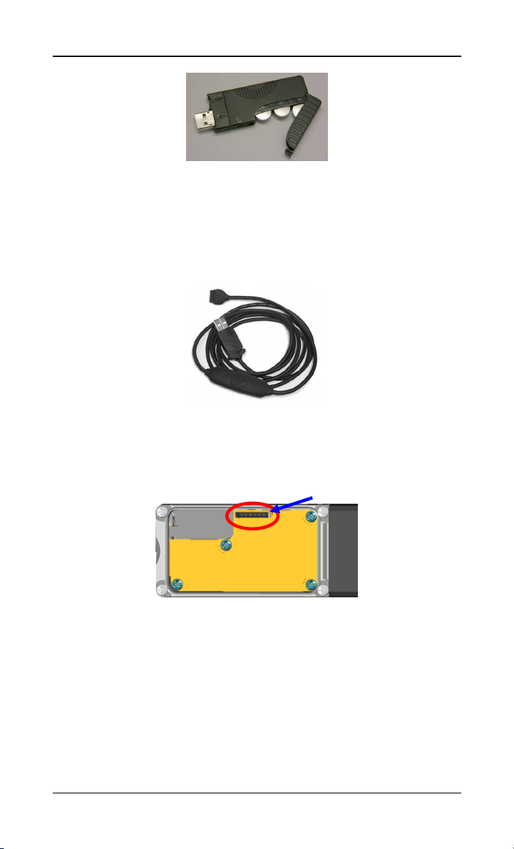
Figure 8, DL1 Remote Downloader
3.2.2 Direct Connect Mode
Using the supplied USB Direct Connect Cable, the TAG-T3
OMBAT can be configured to the desired operational parameters.
W
Figure 9, USB Direct Connect Cable
The cable can do the same interrogation and configuration functions
as the DL1 Remote Downloader. The connector that the USB Direct
Connect Cable plugs into is contained within the TAG-T3.
Pin 1
Figure 10, Direct Connect Cable Connector location
Take care when removing the top cover so as not to damage the seals.
Antistatic precautions should be observed when the cover is not on the
unit.
3.3 Concealment and Tactical Issues
Concealment and tactical issues surrounding the use of the TAG-T3
units are beyond the scope of this guide.
© Geonautics 17 Law Enforcement ONLY
Page 18

TAG-T3 Wombat – User Guide, 1.0.7 Commands
4. COMMANDS
4.1 Command Set Notation
The following pages give a complete list of the TAG-T3’s command
set. Commands may be transmitted to the unit directly using the
Remote Downloader or via the “Direct Connect” cable. All commands
must be terminated with a carriage return / linefeed pair <CR><LF>.
Commands are sent to and received from the TAG-T3 unit in a
comma separated ASCII format. With respect to the command set, the
following notation is used
$GO0 Command identifier
[<Unit_Id >] Optional device serial number
<parameter> Indicates a parameter is required
[,<parameter>] Optional parameter
<parameter|parameter> Choice of parameters i.e. ON|OFF
Sending an appropriately filled out command message to the TAG-
T3 can change the appropriate parameters for that command. It
should be noted that not all values need to be supplied in order to
change a single value of a multiple parameter command. All that is
required is to ensure that there are the correct number of commas so
that the value being set is in the right location.
Any commands sent to the unit with “blank” values will result in that
parameter being queried and the result returned as part of the reply.
e.g. sending a
$GO0,,CLK,,,,
or $GO0,,CLK
or $GO0,Unit_Id,CLK
to the TAG-T3 will return an acknowledgment containing the current
parameters, for example $GOA,T3-001,CLK,0000,36000,60,180
The TAG-T3 will acknowledge all commands sent to it with either
an acknowledgment, or an error message. Command
ACKnowledgments and NACKnowledgments that are returned by a
device, have the following notation
$GOA Command ACKnowledgment identifier
$GON Command Not ACKnowledge identifier
$GOM Unsolicited message identifier
© Geonautics 18 Law Enforcement ONLY
Page 19

TAG-T3 Wombat – User Guide, 1.0.7 Commands
4.2 Standard Position String
$GO0,<Target>,<Operation>,<Unit Id.>,<Date>,<UTC>,
<Lat>,<Long>,<Height>,<Speed>,<Heading>,<Accuracy>,
<No. Of Satellites>,<Quality>,<Log Type>,<Movement Type>
String Parameters Description
Target
Operation
Unit Id.
Date
UTC
Lat
Long
Height
Speed
Heading
Accuracy
No. of satellites
Quality
Log Type
Movement Type
Example:
$GO0,T3-999,EXTERNAL,T3999,08012004,064336,-27.490401,153.037357,50,0,0,3.8,4,1,R,S
$GO0,T3-999,EXTERNAL,T3999,08012004,064337,-27.490401,153.037357,50,0,0,3.8,4,1,R,S
$GO0,T3-999,EXTERNAL,T3999,08012004,064338,-27.490401,153.037357,50,0,0,3.8,4,1,R,S
$GO0,T3-999,EXTERNAL,T3999,08012004,064339,-27.490401,153.037357,50,0,0,3.8,4,1,R,S
The target name of the unit
The operation name of the unit
Unique serial number of the unit
UTC date according to the GPS
UTC time according to the GPS. A UTC
offset must be added to determine the local
time of the point
Latitude of the position, in degrees
Longitude of the position, in degrees
Height of the position in meters
Speed of the position in km/h
Heading of the position, in degrees
Position Dilution Of Precision, PDOP
Number of space vehicles used to calculate
position
Status of position,
0 Position old
1 Position current
Type of log for position,
L Logged position
R Real time position
Type of log for position,
K Speed greater than 10kph
M Unit is being shocked/moved
s Unit
has
been shocked/moved
S Unit is stationary
v Unit has under voltage
V Unit has over voltage
1 Unit has been shocked by trigger 1
Table 3, Standard Position String
© Geonautics 19 Law Enforcement ONLY
Page 20

TAG-T3 Wombat – User Guide, 1.0.7 Commands
4.3 System Configuration
4.3.1 Vehicle (Identification)
Sets / queries a vehicle name and operation name for the TAG-T3
unit.
$GO0,,VEH[,<Target Name>][,<Operation Name>]
$GOA,<Unit_Id>,VEH,<Target Name>,<Operation Name>
Vehicle (Identification) Command Description
Target Name Identifies the Vehicle/Target
Operation Name Identifies the Operation
Table 4, Vehicle (Identification) Command
The target and operation names are used to identify the vehicle and
are limited to 8 characters. Spaces or characters that are illegal in
WindowsTM file names may not be used.
Default: $GO0,,VEH,T3-xxx,INTERNAL
Where xxx is the TAG-T3 serial number.
Example: $GO0,,VEH,FRED,TEST
Returns: $GOA,<Unit_Id>,VEH,FRED,TEST
TAG Comms uses the target name for creating the storage files for
real-time and logged positions.
Real-time positions are stored in <Target Name>.REL
Logged positions are stored in <Target Name>.MEM
© Geonautics 20 Law Enforcement ONLY
Page 21

TAG-T3 Wombat – User Guide, 1.0.7 Commands
4.3.2 Clock
Sets the TAG-T3’s clock parameters.
$GO0,,CLK[,<hhmm>][,<UTC offset>][,<First Sat>][,<Fix>]
$GOA,<Unit_Id>,CLK,<hhmm>,<UTC offset>,<First Sat>,<Fix>
Clock Command Description
hhmm Start time used to commence TRX intervals
UTC Offset
First Sat
Fix
Default: $GO0,,CLK,0000,36000,60,180
Example: $GO0,,CLK,0930,-18000,60,180
Returns: $GOA,<Unit_Id>,CLK,0930,-18000,60,180
In the example shown the TAG-T3 would start its first TRX interval
at the local time of half past nine in the morning and the UTC offset
has been set to -5hrs, US Eastern Time. Subsequent times would be
determined by the values of the TRX (Configuration) command on
page 35.
The UTC Offset is not reset during a RST command.
Seconds from UTC (Greenwich Mean Time) to
local time
Period in seconds in which the GPS tries to
find a satellite
Period in seconds in which the GPS tries to
obtain a position fix
Table 5, Clock parameters
© Geonautics 21 Law Enforcement ONLY
Page 22

TAG-T3 Wombat – User Guide, 1.0.7 Commands
4.3.3 Motion
Sets the motion sensitivity of the movement sensor and the interval
that any single movement is valid.
$GO0,,SHK[,<shock>][,<duration>]
$GOA,<Unit_Id>,SHK,<shock>,<duration>
Motion Command Description
Strength of movement to register motion,
shock
duration
Default: $GO0,,SHK,30,90
Example: $GO0,,SHK,20,120
Returns: $GOA,<Unit_Id>,SHK,20,120
The shock duration should be set longer than the least time we would
expect to see a motion trigger. The duration should be large enough to
allow for stationary times at traffic lights and other periods of
inactivity.
If shock is set to zero (0), the motion sensor will be disabled. Only
experienced users should consider using this option.
1 to 255 where,
1 being most sensitive
255 being the least sensitive
Number of seconds the motion is valid for
from the last movement
Table 6, Motion Command
© Geonautics 22 Law Enforcement ONLY
Page 23

TAG-T3 Wombat – User Guide, 1.0.7 Commands
4.3.4 Voltage
Set the trigger levels for voltage rises and voltage drops. The duration
of the trigger is set by the duration time of the Motion (Configuration)
command. See page 22.
$GO0,,VLT[,<low>][,<high>]
$GOA,<Unit_Id>,VLT,<low>,<high>
Voltage Command Description
low Lower voltage trigger level expressed as volts*10
high Upper voltage trigger level expressed as volts*10
Table 7, Voltage Command
Default: $GO0,,VLT,0,135
Example: $GO0,,VLT,20,120
Returns: $GOA,<Unit_Id>,VLT,20,120
A voltage setting of 135 is interpreted as 13.5 volts.
When setting the high limit to sense the alternator induced voltage
rise, use the Parameter, page 42, or Debug (Last), page 44, command
to establish the voltage when the engine is running and then set the
high value to a voltage slightly under that voltage (0.3 volts lower is
normally sufficient).
© Geonautics 23 Law Enforcement ONLY
Page 24

TAG-T3 Wombat – User Guide, 1.0.7 Commands
4.3.5 Power (Configuration)
Sets or resets the monitoring of the power available to run the unit. For
battery powered units it should be used to count down the available
power of the battery.
$GO0,,POW,<amps>
$GOA,<Unit_Id>,POW,<amps>
Power (Configuration) Command Description
amps
Table 8, Power (Configuration) Command
Initial amount of power available
in amp hours
Default: $GO0,,POW,0
Example: $GO0,,POW,10.0
Returns: $GOA,<Unit_Id>,POW,10.0
If the available power is set to zero the power used will count up from
zero. If available power is set to a number then the power used will
count down.
4.3.6 Backdoor
Turns on or off the TRX midnight backdoor. Backdoor is referenced to
local time.
Note: The midnight backdoor is provided to ensure there is one period
each day that the device can be contacted by TRX even if
parameters are set to values which would prohibit the TRX
coming on. Only experienced users should disable the backdoor.
$GO0,,BDR[,ON|OFF]
$GOA,<Unit_Id>,BDR,ON|OFF
Backdoor Command Description
ON|OFF Turns Backdoor setting ON or OFF
Default: $GO0,,BDR,ON
Example: $GO0,,BDR,OFF
Returns: $GOA,<Unit_Id>,BDR,OFF
Table 9, Backdoor Command
© Geonautics 24 Law Enforcement ONLY
Page 25

TAG-T3 Wombat – User Guide, 1.0.7 Commands
4.4 Positions
4.4.1 Position (Live Track)
Turns on or off real-time tracking.
$GO0,,POS[,ON|OFF]
$GOA,<Unit_Id>,POS,ON|OFF
Position (Live Track) Command Description
ON|OFF Turns real-time tracking ON or OFF
Default: $GO0,,POS,OFF
Example: $GO0,,POS,ON
Returns: $GOA,<Unit_Id>,POS,ON
Real-time positions are updated every second and are turned OFF
automatically, if the TRX connection is lost.
TAG Comms updates the file <Target Name>.REL to store the
positions returned.
Table 10, Position (Live Track) Command
Followed by position strings every 1 second.
$GO0,....... (Standard position string) (see page
19)
........
$GO0,....... (Standard position string) (see page
19)
© Geonautics 25 Law Enforcement ONLY
Page 26

TAG-T3 Wombat – User Guide, 1.0.7 Commands
4.4.2 Position (Last)
Returns the last stored position of the TAG-T3.
$GO0,,POS
$GO0,....... (Standard position string) (see page 19)
Default: Not Applicable
Example: $GO0,,POS
Returns: $GO0,....... (Standard position string) (see page
19)
The Position (Last) command does not force a new position to be
acquired and hence depending on the GPS power management mode
may not be up to date.
TAG Comms updates the file <Target Name>.REL to store the
positions.
© Geonautics 26 Law Enforcement ONLY
Page 27

TAG-T3 Wombat – User Guide, 1.0.7 Commands
4.5 Memory
4.5.1 Memory (New)
Downloads any positions stored in memory that have not previously
been downloaded.
$GO0,,MEM,NEW
……
Memory not previously downloaded
……
$GOA,<Unit_Id>,MEM,NEW
Default: Not Applicable
Example: $GO0,,MEM,NEW
(Assume 500 positions stored with 100 new)
Returns: 401:500
$GO0,....... (Standard position string) (see page 19)
........
........
499:500
$GO0,....... (Standard position string) (see page 19)
500:500
$GO0,....... (Standard position string) (see page 19)
$GOA,<Unit_Id>,MEM,NEW
TAG Comms updates the file <Target Name>.MEM to store the
positions.
Using $GO0,,MEM,NEW prevents duplicates of the positions when
multiple downloads are made.
© Geonautics 27 Law Enforcement ONLY
Page 28

TAG-T3 Wombat – User Guide, 1.0.7 Commands
4.5.2 Memory (All)
Downloads all positions stored in memory.
$GO0,,MEM,ALL
……
Downloads all logged points in memory
……
$GOA,<Unit_Id>,MEM,ALL
Default: Not Applicable
Example: $GO0,,MEM,ALL
(Assume 500 positions logged with 100 new)
Returns: 1:500
$GO0,....... (Standard position string) (see page 19)
........
........
499:500
$GO0,....... (Standard position string) (see page 19)
500:500
$GO0,....... (Standard position string) (see page 19)
$GOA,<Unit_Id>,MEM,ALL
TAG Comms updates the file <Target Name>.MEM to store the
positions.
4.5.3 Memory (Delete)
Deletes all positions stored in memory.
$GO0,,MEM,DEL
$GOA,<Unit_Id>,MEM,DEL
Default: Not Applicable
Example: $GO0,,MEM,DEL
Returns: $GOA,<Unit_Id>,MEM,DEL
Memory which has been deleted may be able to be recovered by using
the Memory (Raw) command of page 31.
© Geonautics 28 Law Enforcement ONLY
Page 29

TAG-T3 Wombat – User Guide, 1.0.7 Commands
4.5.4 Memory (Fix)
Downloads positions in memory, starting at the specified fix number
and continuing until either the end fix number or until last memory
point has been reached.
$GO0,,MEM,FIX[,<Start Fix Number>][,<End Fix Number>]
……
Downloads memory between and including the specified fix
numbers
……
$GOA,<Unit_Id>,MEM,FIX,<Start Fix Number>,<End Fix
Number>
Memory Fix Description
Start Fix Number First fix to download
End Fix Number Last fix to download
Table 11, Memory Fix Command
Default: Not Applicable
Example: $GO0,,MEM,FIX,201,300
(Assume 500 positions logged with 100 new)
Returns: 201:500
$GO0,....... (Standard position string) (see page 19)
........
........
299:500
$GO0,....... (Standard position string) (see page 19)
300:500
$GO0,....... (Standard position string) (see page 19)
$GOA,<Unit_Id>,MEM,FIX
The start and end fix numbers must be in the range of zero to the
current number of logs.
© Geonautics 29 Law Enforcement ONLY
Page 30

TAG-T3 Wombat – User Guide, 1.0.7 Commands
TAG Comms updates the file <Target Name>.MEM to store the
positions.
4.5.5 Memory (Format)
Overwrites the memory, to disable recovery of points with the
Memory (Raw) command of page 31.
$GO0,,MEM,FMT
……
$GOA,<Unit_Id>,MEM,FMT
Default: Not Applicable
Example: $GO0,,MEM,FMT
Returns: Format: 0%
Format: 8%
…
Format: 90%
Format: 98%
$GOA,<Unit_Id>,MEM,FMT
Points must firstly be deleted via the Memory (Delete) command, see
page 28, before this command can be used.
© Geonautics 30 Law Enforcement ONLY
Page 31

TAG-T3 Wombat – User Guide, 1.0.7 Commands
4.5.6 Memory (Raw)
Downloads all 50,000 positions stored in memory regardless of
whether they are valid.
$GO0,,MEM,RAW
……
Downloads entire memory for 1 to 50,000 regardless of their validity
……
$GOA,<Unit_Id>,MEM,RAW
Default: Not Applicable
Example: $GO0,,MEM,RAW
(Assume 500 positions logged with 100 new)
Returns: 1:500
$GO0,....... (Standard position string) (see page 19)
.......
49999:500
$GO0,....... (Standard position string) (see page 19)
50000:500
$GO0,....... (Standard position string) (see page 19)
$GOA,<Unit_Id>,MEM,RAW
This command should only be used if memory previously deleted
needs to be recovered. Any points overwritten will not be recovered.
TAG Comms updates the file <Target Name>.MEM to store the
positions.
© Geonautics 31 Law Enforcement ONLY
Page 32

TAG-T3 Wombat – User Guide, 1.0.7 Commands
4.6 Alarms
4.6.1 Movement
For the duration of any series of movements of the TAG-T3, the unit
can fire the External Relay Trigger.
$GO0,,MOV[,<Relay ON|OFF>]
$GOA,<Unit_Id>,MOV,<Relay ON|OFF>
Movement (Alarm) Description
Movement
Alarm
Relay Number
Table 12, Movement (Alarm) Command
Default: $GO0,,MOV,OFF
Example: $GO0,,MOV,ON
Returns: $GOA,<Unit_Id>,MOV,ON
Fire relay while motion detected,
see 4.9.1, otherwise OFF
© Geonautics 32 Law Enforcement ONLY
Page 33

TAG-T3 Wombat – User Guide, 1.0.7 Commands
4.6.2 Region (GeoFence)
As the TAG-T3 moves in or out of the area, the unit will fire the
External Trigger Relay.
$GO0,,RG1[,<North>][,<South>][,<East>][,<West>]
[,<Relay ON|OFF,][,<Name>]
$GOA,<Unit_Id>,RG1,<North>,<South>,<East>,<West>,
<Relay ON|OFF>,<Name>
Region (Alarm) Description
North The northern limit of the region (latitude in degrees)
South The southern limit of the region (latitude in degrees)
East The eastern limit of the region (longitude in degrees)
West The western limit of the region (longitude in degrees)
Relay
Name Name of Region Alarm
Fire relay when inside region, OFF to disable, see 4.9.1
Table 13, Region (Alarm) Command
Default: $GO0,,RG1,0.0,0.0,0.0,0.0,OFF,ONE
Example: $GO0,,RG1,-27.5,-27.6,153.2,153.1,ON,BOX_1
Returns:
$GOA,<Unit_Id>,RG1,27.5,27.6,153.2,15
3.1,ON,BOX_1
Note: When the alarm is triggered and relay is set, the unit will fire
the external Relay Trigger.
© Geonautics 33 Law Enforcement ONLY
Page 34

TAG-T3 Wombat – User Guide, 1.0.7 Commands
4.6.3 Input Triggering
Turn ON and OFF the acknowledgement of input triggering. With the
command enabled the motion sensing will display a “1” for any
external triggers that cause motion. See page 22.
$GO0,,TRG[,<Motion ON|OFF>]
$GOA,<Unit_Id>,TRG,<Motion ON|OFF>,<State HI|LO>
Input Trigger Command Description
Motion
State
Table 14, Input Trigger Command
Default: $GO0,,TRG,OFF,
Example: $GO0,,TRG,ON
Returns: $GOA,<Unit_Id>,TRG,ON,HI
From the example above, the input triggering acknowledgment is
turned ON. The state of the trigger at the time of the command is also
returned as HI.
When set to ON, trigger is enabled, OFF
to disable
When command is acknowledged it will
return the current state of the input
trigger, HI or LO
© Geonautics 34 Law Enforcement ONLY
Page 35

TAG-T3 Wombat – User Guide, 1.0.7 Commands
4.7 TRX
4.7.1 TRX (Configuration)
Specifies the TRX operational parameters.
$GO0,,TRX[,<Interval>][,<Period>][,<Power Management>]
$GOA,<Unit_Id>,TRX,<Interval>,<Period>,<Power Management>
GSM Command Description
Interval
Period
Power Management
Default: $GO0,,TRX,1800,180,0
Example: $GO0,,TRX,0,180,0
Returns: $GOA,<Unit_Id>,TRX,0,180,0
Setting the TRX interval to zero forces the TRX to be permanently on.
The interval is aligned to the start time and local time parameters of
the Clock command of page 21.
Number of seconds between the TRX
turning on
Number of seconds for the TRX to stay
ON, minimum 60 secs
TRX ON according to Interval and Period
0
timers
TRX ON during each Interval and when
1
movement sensed
Table 15, TRX Command
© Geonautics 35 Law Enforcement ONLY
Page 36

TAG-T3 Wombat – User Guide, 1.0.7 Commands
4.7.2 TRX (Echo)
Implements a pass through mode where all communications via the
“Direct Connect” port are echoed directly to the TRX, likewise all
communications from the TRX are sent to the “Direct Connect” port.
Note: This command is for debugging purposes and should only be
used by experienced users.
$GO0,,ECO,TRX[,ON|OFF]
$GOA,<Unit_Id>,ECO,TRX,ON|OFF
TRX (Echo) Description
ON|OFF Turns TRX Echo ON or OFF
Table 16, TRX (Echo) Command
Default: $GO0,,ECO,TRX,OFF
Example: $GO0,,ECO,TRX,ON
Returns: $GOA,<Unit_Id>,ECO,TRX,ON
While this command is on all TRX communications
will be echoed to the “Direct Connect” port.
This command is reset to OFF whenever power is removed from the
unit.
© Geonautics 36 Law Enforcement ONLY
Page 37

TAG-T3 Wombat – User Guide, 1.0.7 Commands
4.8 GPS
4.8.1 GPS (Configuration)
Specifies the GPS operational parameters.
$GO0,,GPS[,<Interval>][,<Force Logs>][,<Power Management>]
$GOA,<Unit_Id>,GPS,<Interval>,<Force Logs>,<Power
Management>
GPS Command Description
Interval
Force Logs
Power Management
Table 17, GPS (Configuration) Command
Default: $GO0,,GPS,30,0,3
Example: $GO0,,GPS,60,1,3
Returns: $GOA,<Unit_Id>,GPS,60,1,3
Setting the GPS interval to zero, forces the GPS to be permanently off.
The GPS will also come on as required to perform real-time tracking.
If Interval is set to zero (0), GPS is turned OFF and will not turn on
when movement is sensed. Only experienced users should consider
using this option.
Number of seconds between
commencing a GPS log
0 Positions only logged while moving
Force positions to be logged
1
GPS ON always
0
GPS turns off between logs or when
1
timeouts occur, see page 21 for
information on timeouts
GPS ON when movement sensed
2
GPS turns off between logs but
3
ignores timeouts if motion is detected
© Geonautics 37 Law Enforcement ONLY
Page 38

TAG-T3 Wombat – User Guide, 1.0.7 Commands
4.8.2 GPS (Reset)
Forces the GPS to reset and begin a sky search, whilst ignoring
previous almanac, ephemeris and stored position data.
$GO0,,GPS,RST
$GOA,<Unit_Id>,GPS,RST
Example: $GO0,,GPS,RST
Returns: $GOA,<Unit_Id>,GPS,RST
Note: The GPS unit must be ON when command is sent to unit,
see page 37.
4.8.3 GPS (Echo)
Implements a pass through mode where all communications from the
GPS are passed back through the current connection.
Note: This command is for debugging purposes and should only be
used by experienced users.
$GO0,,ECO,GPS[,ON|OFF]
$GOA,<Unit_Id>,ECO,GPS,ON|OFF
GPS (Echo) Description
ON|OFF Turns GPS Echo ON or OFF
Table 18, GPS (Echo) Command
Default: $GO0,,ECO,GPS,OFF
Example: $GO0,,ECO,GPS,ON
Returns: $GOA,<Unit_Id>,ECO,GPS,ON
While this command is on, all communications from
the GPS will be echoed to the current connection.
This command is reset to OFF whenever power is removed from the
unit.
© Geonautics 38 Law Enforcement ONLY
Page 39

TAG-T3 Wombat – User Guide, 1.0.7 Commands
4.8.4 GPS (Sats)
Returns the Satellite constellation and signal strengths currently seen
by the GPS module.
$GO0,,SATS
$GOA,<Unit_Id>,SATS
,<Sv1ID>,<Sv1 Sig>,<Sv1 Elev>,<Sv1 Azimuth>
,<Sv2ID>,<Sv2 Sig>,<Sv2 Elev>,<Sv2 Azimuth>
…
,<SvNID>,<SvN Sig>,<SvN Elev>,<SvN Azimuth>
Default: Not Applicable
Example: $GO0,,SATS
Return: $GOA,<Unit_ID>,SATS,2,5.00,18,128,5,
9.20,49,353,6,8.20,46,213,10,12.40,52,122,30,8.80,6
5,288,21,0.00,-90,0,23,0.00,-90,0,24,0.00,-90,0
Note: The Signal strength ranges from 0 to 25, with the higher the
number the better the signal strength. If the signal level is
negative then that satellite is not yet locked in.
Both the Elevation and Azimuth are in degrees
Using this command within Geonautics’ range of tracking programs
will allow the user to see the constellation visually.
GPS Command Description
SvN ID
Satellite N
SvN Sig
SvN Elev
SvN Azimuth
Table 19, SATS Command
Above table shows the responses that will be returned for each space
vehicle, up to N space vehicles.
Space Vehicle N ID
Space Vehicle N Signal Strength
Space Vehicle N Elevation
Space Vehicle N Azimuth
© Geonautics 39 Law Enforcement ONLY
Page 40

TAG-T3 Wombat – User Guide, 1.0.7 Commands
4.8.5 GPS (Health)
Returns the current “health” of the GPS module.
$GO0,,HEALTH
$GOA,<Unit_Id>,HEALTH,<nSVS>,<almanac>,<antenna>
,<backup>,<nav fware>,<dsp fware>,<date>,<time>
GPS Health Command Description
nSVS
almanac
antenna
backup
nav fware
dsp fware
date
time
Table 20, GPS Health Command
Default: Not Applicable
Example: $GO0,,HEALTH
Returns: $GOA,<Unit_Id>,HEALTH,7,0,1,1,1.04,2.12,
27102004,052342
Number of Space Vehicles currently locked onto
Indicates whether the Almanac is complete,
0 No
1 Yes
Indicates whether the receiver is receiving RF,
0 No
1 Yes
Indicates whether battery backup is present,
0 No
1 Yes
Navigation firmware revision
DSP firmware revision
GPS date of the last calculated fix,
ddmmyyyy
GPS time of the last calculated fix, hhmmss
© Geonautics 40 Law Enforcement ONLY
Page 41

TAG-T3 Wombat – User Guide, 1.0.7 Commands
4.9 Miscellaneous
4.9.1 Relay Triggering
Turn ON or OFF an internal short to power ground so that an
externally wired relay can be triggered.
$GO0,,RLY[,ON|OFF|<time>]
$GOA,<Unit_Id>,RLY,ON|OFF
Relay Triggering
Command
ON|OFF Turns Relay Trigger ON or OFF
time
Turns ON the short to power ground for
<time> tenths, then turns the short OFF.
Table 21, Relay Command
Default: $GO0,,RLY,OFF
Example: $GO0,,RLY,50
Returns: $GOA,<Unit_Id>,RLY,OFF
In the example shown the TAG-T3 would turn the trigger output, ON
for 5 seconds, then turn the output OFF, resulting in the OFF
message.
Sending $GO0,,RLY queries the current state of the relay trigger
e.g. $GOA,<Unit_Id>,RLY,ON.
Note: This output can be used to fire an external relay (up to 250mA),
see page 48.
Description
© Geonautics 41 Law Enforcement ONLY
Page 42

TAG-T3 Wombat – User Guide, 1.0.7 Commands
4.9.2 Parameters
Returns the current operating parameters of the TAG-T3.
$GO0,,PAR
"Target Name" Logs:50000 NewLogs SerialNo.
Time
Trx=Interval,Period,PowerManagement
GPS=Interval,Force,PowerManagement
Current=Used:Size Voltage
Movement=Relay
Region1=Relay,Name
Firmware
Target Name
Logs
New Logs
Serial No.
Time
Trx
GPS
Current
Movement Relay
Region1
Firmware
Default: Not Applicable
Example: $GO0,,PAR
Returns: FRED 500:50000 100 T3-099
Alarms and Functions set to OFF are removed from the listing.
Parameters Description
Identifies the vehicle
Total number of logged positions
Logged positions that haven’t been
previously downloaded
Serial number of the unit
Current local time of unit
TRX settings
GPS settings
Used
Size
Voltage
Relay
Name
Current consumed since last reset
Current figure set
Current Input Voltage on the unit
Turns Relay Trigger ON or OFF
Turns Relay Trigger ON or OFF
Name of Region
Unit firmware version
Table 22, Parameters
11:47:11
Trx=1800,180,0
G=30,0,3
C=0.1:0.0 11.9v
R1=ON,ONE
T3.1.0.13
© Geonautics 42 Law Enforcement ONLY
Page 43

TAG-T3 Wombat – User Guide, 1.0.7 Commands
4.9.3 Debug (Live)
Turn on and off the debugging information.
$GO0,,DBG[,ON|OFF]
$GOA,<Unit_Id>,DBG,ON|OFF
When ON, the following debug information is output every second.
$GOM,<Unit_Id>,DBG,<ModulesStatus>,<LocalTime>,,<TRXTime
r>
,<GPSTimer>,<BackdoorTimer>,<SpaceVehicles>,<Logs>,<Voltag
e>
,<Current>,<Temperature>,<MotionStatus>,<MotionTimer>
Debug String Description
Module
Status
Local Time Local Time of unit, represented as hh:mm:ss
TRX Timer
GPS Timer
Backdoor Timer
Space Vehicles
Logs
Voltage
Current
Temperature
Motion Status
Motion Timer
-|B
-|T
-|G if GPS is currently ON, otherwise -
if TRX is currently ON due to the backdoor interval,
otherwise if TRX is currently ON, otherwise -
Counts down to zero when TRX ready to turn ON,
otherwise up ‘til the TRX has completed its interval
Counts down to zero when GPS ready to turn ON,
otherwise up ‘til the GPS has completed its interval
Up to 120 when backdoor ON, otherwise shows the
time ‘til midnight
Satellites used in the current GPS solution fix
Number of logged positions currently stored on device
Input Voltage on device
Current being used by device, expressed as mA
Temperature of device in degrees C, low accuracy
Status of the motion sensing
S: Stationary
s: Stationary but yet to complete final log
M: Movement sensor
T: External trigger
v: Under voltage
V: Over voltage
Counts down to the completion of the motion
Table 23, Debug String
© Geonautics 43 Law Enforcement ONLY
Page 44

TAG-T3 Wombat – User Guide, 1.0.7 Commands
Default: $GO0,,DBG,OFF
Example: $GO0,,DBG,ON
Returns: $GOA,<Unit_Id>,DBG,ON
Followed by a series of strings,
$GOM,T3e-003,DBG,--G,06:11:18,6522 ,1,64122,5,1054,12.4v,33,27,M,85
$GOM,T3e-003,DBG,--G,06:11:19,6521 ,0,64121,5,1054,12.4v,32,27,M,84
$GOM,T3e-003,DBG,--G,06:11:20,6520 ,0,64120,5,1054,12.5v,32,27,M,89
$GOM,T3e-003,DBG,--G,06:11:21,6519 ,30,64119,5,1055,12.5v,33,27,M,89
$GOM,T3e-003,DBG,--G,06:11:22,6518 ,29,64118,5,1055,12.5v,33,27,M,89
……
……
$GOM,T3e-003,DBG,--G,06:11:32,6508 ,19,64128,5,1055,12.5v,32,27,M,89
4.9.4 Debug (Last)
Displays the most recent debug information.
$GO0,,DBG
$GOM,<Unit_Id>,DBG,<ModulesStatus>,<LocalTime>,,<TRXTime
r>
,<GPSTimer>,<BackdoorTimer>,<SpaceVehicles>,<Logs>,<Voltag
e>
,<Current>,<Temperature>,<MotionStatus>,<MotionTimer>
See Debug (Live) for parameter descriptions, page 43.
Default: Not Applicable
Example: $GO0,,DBG
Returns: $GOM,T3e-003,DBG,--
G,06:11:32,6508,19,64128,5,1055,12.5v,32,27,M,89
© Geonautics 44 Law Enforcement ONLY
Page 45

TAG-T3 Wombat – User Guide, 1.0.7 Commands
4.9.5 Power (Query)
Queries how much power has been used by the TAG-T3.
$GO0,,POW
$GOA,<Unit_Id>,POW,<amps>:<amps available>
Power (Query) Command Description
Power measured in amps, remaining if
amps
amps available
Table 24, Power (Configuration) Command
<amps available> is non zero otherwise
power used.
Power as set by the Power
(Configuration) command, see page 24
Default: Not Applicable
Example: $GO0,,POW
Returns: $GOA,<Unit_Id>,POW,0.348:1.000
$GO0,,PAR also displays the power used/remaining, see page 42.
4.9.6 Shutdown
Shuts the TAG-T3 down by disabling everything and placing the unit
into sleep mode. The unit will wake up again at midnight and operate
according to current parameter settings thereafter.
Note: This command makes the device unreachable until the next
local midnight occurs. This command should only be used by
experienced users.
$GO0,,SHT
$GOA,<Unit_Id>,SHT
Default: Not Applicable
Example: $GO0,,SHT
Returns: $GOA,<Unit_Id>,SHT
© Geonautics 45 Law Enforcement ONLY
Page 46

TAG-T3 Wombat – User Guide, 1.0.7 Commands
4.9.7 Shutdown (Reset)
If a unit is inadvertently sent the Shutdown command, 4.9.6, then the
unit can be “reset” to operate again as per user settings.
Note: This command can only be sent via Direct Connect. This
command should only be used by experienced users.
$GO0,,SHT,RST
$GOA,<Unit_Id>,SHT
Default: Not Applicable
Example: $GO0,,SHT,RST
Returns: $GOA,<Unit_Id>,SHT,RST
4.9.8 SuperReset
Resets all parameters to their factory default values and forces a
restart of the system.
$GO0,,RST
$GOA,<Unit_Id>,RST
$GOM,<Unit_Id>,RST
Example: $GO0,,RST
Returns: $GOA,<Unit_Id>,RST
The reset command terminates any connections and turns off the TRX.
After reset the TRX will be turned back on for the backdoor period of
120 seconds.
By default the TRX will be set to come on for three minutes every half
hour and the GPS will revert to thirty second logging on movement with
the GPS turned on when motion is detected (power management 3).
For default TRX (Configuration) see page 35.
For default GPS (Configuration) see page 37.
© Geonautics 46 Law Enforcement ONLY
Page 47

TAG-T3 Wombat – User Guide, 1.0.7 Troubleshooting and FAQ
5. TROUBLESHOOTING AND FAQ
If you are having trouble connecting to your TAG-T3 unit, some tips
are below on how to re-establish contact.
If the problem is occurring during RF Communications,
ensure that the communications settings are correct, refer to
the
TAG Comms
When a device is not powered for long periods or moves a
great distance while turned OFF, the GPS can take longer
than normal to calculate its first new position. When trying to
force the GPS into calculating a position, set the GPS power
management to always ON (0), then give the unit a GPS,
RST, ensuring the antenna can see sky. Having the unit
stationary may help fast track this operation.
Default TRX interval is ON for 3 mins each half hour, on the
half hour, referenced to local time. When device is first
powered, local time could be incorrect until the GPS can see
the sky and update its internal clocks.
Consult your
DL1 Remote Downloader
Contact your local Geonautics representative.
user guide for further information.
TAG Comms
user guide on updating drivers for
© Geonautics 47 Law Enforcement ONLY
Page 48
Wombat – User Guide, 1.0.7 APPENDIX A
APPENDIX A EXTERNAL RELAY TRIGGERING
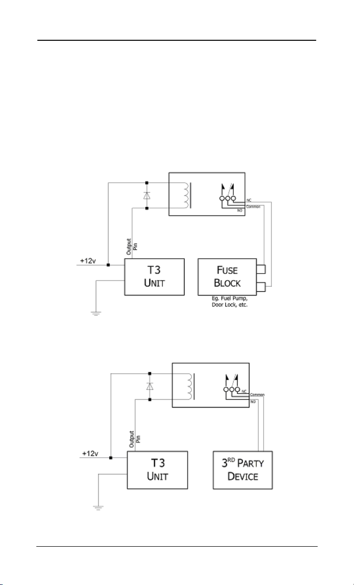
An internal short to power ground can be utilized, so that an external
relay can be triggered to ENABLE / DISABLE 3rd party devices. The
internal 6 Pin Datamate Connector, page 49, is used to connect the
external relay to the TAG-T3. This output is protected internally by a
0.25A fuse. To trigger the external relay when connected, the
command $GO0,,RLY (page 41), is used. Wiring examples can be
found below.
Figure 11, To DISABLE External Devices using the TAG-T3
Figure 12, To ENABLE External Devices using the TAG-T3
© Geonautics 48 Law Enforcement ONLY
Page 49
Wombat – User Guide, 1.0.7 APPENDIX A
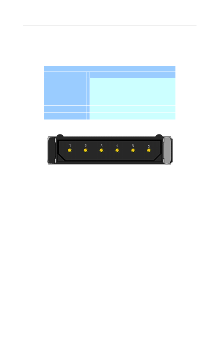
A 6 pin connector is located, see Figure 10, under the top cover of the
TAG-T3. This connector is used to connect to the USB Direct
Connect cable or an external device to trigger.
6 Pin Data Connector
Pin Connection
1 GND
2 Sense
3 Data Out
4 Data In
5 I/O (External Trigger)
6 V+ (USB 5V)
Table 25, 6 Pin Data Connector
Figure 13, 6 Pin I/O Connector
© Geonautics 49 Law Enforcement ONLY
Page 50

Wombat – User Guide, 1.0.7 APPENDIX B
APPENDIX B SPECIFICATIONS
B.1 TAG-T3 Specification
Property Specification
Size
Weight
Housing
Storage Temperature
Temperature
Operating Voltage 5 to 24v DC
Operating
Current
(typical)
GPS Only 30 mA
TRX – RX Mode 10 mA
TRX – TX Mode 15 mA
Maximum 35 mA
Sleep Current < 700 µA (typical)
GPS Engine Trimble Lassen iQ
RF Frequency 916.5 or 868.35 MHz (Factory Set)
Logged Storage 50,000 Points
B.2 TAG-T3 Kit
Property
TAG-T3 Kit TAG-T3 Tracker Core
mm 120 mm x 40 mm x 24 mm
3/4”
inches
4
x 1
1/2”
x 15/16”
approx. 100g
º
C -20 to 70
º
F -5 to 160
º
C -20 to 55 Operating
º
F -5 to 130
ABS/PC, IP67
Table 26, TAG-T3 Specifications
Description
Remote Downloader
External GPS Antenna
9V Battery Cover
9V Battery
External Power connector with cover
Magnetic Plate and Keeper
USB “Direct Connect” Cable
Software for downloading
User Guide
Plastic Case
Table 27, TAG-T3 Kit
© Geonautics 50 Law Enforcement ONLY
Page 51

Wombat – User Guide, 1.0.7 APPENDIX C
APPENDIX C COMMAND REFERENCE
Command Page Description
System Configuration
Vehicle (Identification) 20
Clock 21
Motion 22 $GO0,,SHK,<Sensitivity>,<Duration>
Voltage 23 $GO0,,VLT,<Low>,<High>
Power 24 $GO0,,POW,<Capacity>
Backdoor
Positioning
Position (Live Track)
Position (Last) 26 $GO0,,POS
Memory
Memory (New) 27 $GO0,,MEM,NEW
Memory (All) 28 $GO0,,MEM,ALL
Memory (Delete) 28 $GO0,,MEM,DEL
Memory (Fix) 29 $GO0,,MEM,FIX,<Start Point>,<End Point>
Memory (Format) 30 $GO0,,MEM,FMT
Memory (Raw) 31 $GO0,,MEM,RAW
Alarms
Movement 32
Regions (GeoFences) 33
Input Triggering 34 $GO0,,TRG[,<Motion ON|OFF>]
TRX
TRX (Configuration) 35
TRX (Echo) 36 $GO0,,ECO,TRX,<ON|OFF>
GPS
GPS (Configuration) 37 $GO0,,GPS,<Interval>,<Force>,<Power Mgmt>
GPS (Reset) 38 $GO0,,GPS,RST
GPS (Echo) 38 $GO0,,ECO,GPS,<ON|OFF>
GPS (Sats) 39 $GO0,,SATS
GPS (Health) 40 $GO0,,HEALTH
Miscellaneous
Relay Triggering
Parameters
Debug (Live) 43 $GO0,,DBG,<ON|OFF>
Debug (Last) 44 $GO0,,DBG
Power (Query) 45 $GO0,,POW
Shutdown 45 $GO0,,SHT
Shutdown (Reset) 46 $GO0,,SHT,RST
Super Reset 46 $GO0,,RST
$GO0,,VEH,<Target>,<Operation>
$GO0,,<hhmm>,<UTC Offset>,<First Sat>,<Fix>
24 $GO0,,BDR,<ON|OFF>
$GO0,,POS,<ON|OFF>
25
$GO0,,MOV[,<Relay ON|OFF>]
$GO0,,RG1[,<North>][,<South>][,<East>][,
<West>][,<Relay ON|OFF,][,<Name>]
$GO0,,TRX,<Interval>,<Period>,<Power Mgmt>
41 $GO0,,RLY[,ON|OFF|<time>]
42 $GO0,,PAR
T
able 28, Commands
© Geonautics 51 Law Enforcement ONLY
Page 52

Wombat – User Guide, 1.0.7 APPENDIX D
APPENDIX D GEONAUTICS’ PLAIN ENGLISH WARRANTY
We aren’t lawyers but our lawyers thought it would be a good idea to explain
how we stand behind our products. This is a simple explanation of how our
warranty works.
What is covered by our Warranty?
All products manufactured by Geonautics are covered by a warranty.
What Items are not covered by Warranty?
Geonautics does not cover batteries and disposable accessories that are related
to the products you bought. We do not cover microphones and equipment that
are normally damaged in field use.
We do not cover acts of God or circumstances outside our control such as
lightning strikes, accident or mistreatment damage; or
Independently warranted items that are bought through Geonautics but are not
manufactured by Geonautics, such as the TTI RF range. If, for example you
buy a receiver or a computer through us and it breaks down you will have to
talk to the manufacturer.
How long is the Warranty good for?
Our warranty is the standard one year warranty from the date we shipped the
goods from our office. Our solid state items such as A1, A2 and A3 digital
recorders receive an additional warranty from us and are covered for a total of
3 years.
What do I have to do to claim my Warranty?
You will need to do the following:
Notify us within 14 days of becoming aware that there is a problem with your
product;
Return the products to Geonautics or their representative in your area at your
cost (we do not accept COD deliveries); and
Be patient while we check the equipment to make sure that the problem is a
genuine problem and hasn’t arisen because of any misuse, neglect, improper
installation, storage, accident or other damage that really shouldn’t be our
problem.
© Geonautics 52 Law Enforcement ONLY
Page 53

Wombat – User Guide, 1.0.7 APPENDIX D
How does our Warranty protect you?
Once we have satisfied ourselves that there is a problem with the product we
will either repair it, replace it or issue you with a credit or refund for the
products. Any replacement provided to you will continue to carry the
remainder of your existing warranty. We try to use new parts wherever
possible when making warranty repairs but sometimes it is not possible to
source replacement parts for older products and a refurbished part may be
used in repairing your product.
Lawyer Stuff
Our lawyers need us to put in another bit here with lots of legal jargon.
Geonautics does not provide any other express warranties for its products or
imply further terms in its warranty which are not printed here. This includes
warranties relating to the product being fit for any particular purpose or being
of a certain merchantable quality.
Geonautics will not be liable for any damage caused by the failure of any
product or associated software. In particular, neither Geonautics nor any
associated company, distributor, re seller, agent or employee shall be liable to
any party for any loss of profit or any other commercial damage including, but
not limited to special, incidental, consequential, collateral or other damages
arising from the provision of our products, associated software or accessories
as a consequence of any cause or event whatsoever.
If any provision of this warranty or its application to any party, person or
circumstances is invalid or unenforceable, for any reason then the remainder
of this warranty shall not be effected because of it and shall remain.
This warranty extends only to the original purchaser or registered user. The
warranty may be transferred to other users with the written approval of
Geonautics.
© Geonautics 53 Law Enforcement ONLY
 Loading...