


Installation and Operating Instructions
GENERATOR SAFETY TRANSFER SWITCH MODELS 2026, 3028
Thank you for purchasing a GenTran® Manual Transfer Switch designed to safely connect a portable generator to the load center in your home or business (single phase only) for standby power applications. Product features include:
•Generator and Utility feeds mechanically interlocked to prevent dangerous utility or generator back feeding – thereby avoiding property damage and serious injury to electrical workers.
•Pre wired for fast, easy connection to the load center
•Each model can be expanded to up to 10 circuits using interchangeable type circuit breakers – so as your needs change, just expand it!
•Accommodates GFCI and Arc-Fault breakers to meet the latest NEC requirements.
•Dual wattmeters are provided to help you monitor and balance the loads on your generator, prolonging generator life
•Flexible generator connections – Use the Power Inlet for a quick cord connection to your generator, or ask your contractor to hardwire your generator connection.
•Surface or Flush Mounting (with flush mounting plate sold separately).
Warning: Gen/Tran transfer switches should be installed by a professional electrician familiar with electrical wiring and codes, and experienced in working with generators. Gen/Tran accepts no responsibility for accidents, damages or personal injury caused by incorrect installation. These transfer switches are intended for surface mounting INDOORS only. GenTran transfer switches are UL listed to UL Standard 1008 and meet the criteria of National Electrical code Article 702.6 for Optional Standby Systems.
Caution: If using the generator and transfer switch for larger appliances, such as electric water heaters, clothes dryers, electric ranges and small air conditioners, check the labels on the appliances to be sure they do NOT exceed the rating of the generator. No appliance should have an amperage rating that exceeds the individual breaker rating in the transfer switch (20 or 30 amps).
Model: |
2026 |
3028 |
# Circuits Provided |
6 |
8 |
Max # Circuits |
10 |
10 |
REQUIRED BREAKER FOR MAIN LOAD CENTER |
60 amp 2-pole |
60 amp 2-pole |
(not included in this kit) |
|
|
Breakers Provided with Unit |
2 – 15 amp 1-pole |
2 – 15 amp 1-pole |
|
2 – 20 amp 1-pole |
2 – 20 amp 1-pole |
|
1 – 20 amp 2-pole |
1 – 20 amp 2-pole |
|
|
1 – 30 amp 2-pole |
Max GEN Watts |
5000 |
7500 |
Max GEN Amps |
20 Amps |
30 Amps |
Voltage |
120/240 Volts |
120/240 Volts |
NEMA Type Enclosure |
1 – Indoor Only |
1 – Indoor Only |
NEMA Configuration of Male Inlet |
L14-20 |
L14-30 |
Phase |
1 |
1 |
Minimum Gauge Cord Size |
12/4 |
10/4 |
Tools Needed for Installation:
• |
Power Drill |
• Wall anchors and screws |
|
• Wire Stripper and cutter |
• |
Other supplies needed if hardwiring to a Power Inlet |
|
• |
Screw drivers |
|
Box include Romex, ½” connector, and wire connectors |
• |
Tape measure |
• |
2-pole 60 amp breaker for main panel |

Planning Your Transfer Switch Installation:
1. Determine the appliances, circuits or equipment you want to operate with generator power during a power outage, such as:
• |
Refrigerator/Freezer |
• |
Water Heater |
• |
Security System |
• Furnace Blower (gas/oil only) |
• |
Garage Door Opener |
• |
Sump Pump |
|
• |
TV / Radio |
• |
Microwave, Coffee Maker |
• Computer, Fax and Printer |
|
• |
Lights |
• |
Well Pump |
• |
Cordless Telephone |
2.Determine the amps required for each appliance by reading the label on the appliance. IMPORTANT: No appliance should have an amperage rating that exceeds the individual breaker rating in the transfer switch. The total amperage of all circuits can exceed the generator rating, but not all circuits will be able to be used concurrently. Do not connect a 50-amp circuit (such as central air conditioning or Electric Range) to this system. GenTran is not responsible for accidents or property damage due to incorrect or inappropriate installation.
3.Assign the circuit # in the load center and in the GenTran® transfer switch, matching the size of the circuit breaker in the load center to the circuit breaker in the transfer switch. Once you’ve determined which circuits you want to connect and the appropriate amperage, you will be ready to begin installing your GenTran® transfer switch.
4.The location of your load center/electrical panel in your home or business will determine where the GenTran® transfer switch will be installed. Refer to the illustrations below. In addition to the transfer switch, you may need additional accessories to complete your generator transfer switch installation, such as a generator cord and power inlet box. A generator cord (sold separately) is needed to connect your generator to the GenTran® transfer switch or power inlet box. If your load center is in your garage, we recommend at least a 25-foot generator cord to reach from your generator outside the garage on the driveway to the transfer switch. NEVER run a generator in an enclosed area! If your load center is in a basement or interior room, you shall install a power inlet box (sold separately) on the exterior of your house or building to avoid running the generator cord through a door or window. Once you have all of the essential components for your specific needs, you may proceed with the installation.
HARDWIRED/BASEMENT INSTALLATION: |
TYPICAL GARAGE INSTALLATION: |
Power Inlet Box
25 ft. Power Cord
Installation Procedure:
IMPORTANT: Please read this entire procedure before beginning installation. WARNING: For SAFETY, turn OFF the MAIN circuit breaker in the load center BEFORE starting installation. Remember, the wiring ahead of the MAIN is HOT, even when the main circuit breaker is off.
Installations with a Generator Cord Connection (Garage Installations):
1.Select a location on right or left side of load center approximately 12 inches to the side of the load center.
2.Find a knockout (KO) on the lower side of the load center that matches the conduit fitting size provided with the Transfer Switch (1” on both models).
3.Remove the cover from the load center and the knockout selected in step 2.
4.Determine if the conduit length provided needs to be shortened. If so, remove the wires from the conduit before cutting to avoid damaging the wires. Then use a utility knife to cut conduit to desired length. . [NOTE: The Electrical Non-Metallic Tubing (ENT)
2
is UL Listed and recognized by the National Electrical Code (NEC). However, it generally cannot be used in buildings that exceed
(3) floors above grade. While the NEC does allow its use for this application, local codes and inspectors may prohibit its use in your area. If this situation exists, call 888-GEN-TRAN to request a length of flexible metal conduit (FMC) to use in its place.]
5.Assemble the conduit to the load center and transfer switch after putting the wire harness through the selected knockout in the load center.
6.Without stressing the flexible conduit, turn the transfer switch to a vertical position, use the enclosed template to mark the hole locations, and anchor the unit to the wall.
Hardwired Installations from a Power Inlet Box to the Transfer Switch (Basement Installations):
1.Follow steps 1 thru 6 above.
2.To remove the male inlet from lower front of transfer switch, remove the three (3) screws that secure it to the frame. Pull it directly out. Then loosen the screws that secure the wires into the flanged inlet. Remove and set aside the four (4) screws (2 on the top, 2 on the bottom) securing the cover. Pull off the cover.
3.Five (5) ½” knockouts are provided for easy wiring using Romex or conduit. Locate and remove your desired knockout. Then insert connector and locknut followed by the wires.
4.Feed sufficient wire into the transfer switch so that it can be pulled 4” through the removed inlet hole.
5.Connect the wires you just fed through to the four wires removed from the male inlet using wire connectors (provided by installer). Connect black to black, red to red, and so on.
6.Push wires and wirenuts back into the cavity in the lower portion of the transfer switch. Use the closing plate provided in the hardware kit to cover the hole left by removing the male inlet.
7.Neatly route the Romex out to the Power Inlet Box. Be sure to secure it according to code along the way.
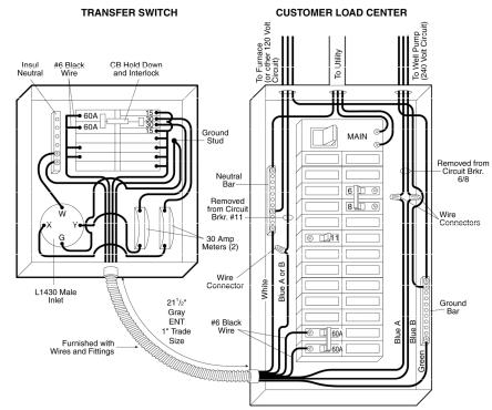
Wiring your GenTran® Transfer Switch to the Load Center:
1.Please note on the transfer switch that each circuit breaker is rated at 15 amps, 20 amps or 30 amps (on model 3028 only).
2.Installer MUST select the same breaker size in the load center for each circuit in the transfer switch (ie: 15 amps only with 15 amps, 20 amps only with 20 amps, etc.).
3.It is recommended that the MAIN circuit breaker in the Load Center be turned OFF while connecting the wires from the transfer switch to those in the Load Center. Remember that the wires ahead of the MAIN BREAKER are still HOT, and could cause serious injury or death if not handled properly. Use extreme CAUTION when wiring inside a LIVE load center.
4.From the harness wires now in the load center, locate wire A4. Then select a
Model 3028 |
desired circuit breaker in the load center |
|
with the same rating (ex: 15 amps). See |
|
|
|
Wiring Diagram at left. |
|
5. Turn off this selected breaker and remove |
|
the wire from the breaker in the LC. |
|
Connect Blue wire using a wirenut to the |
|
wire removed from the breaker. |
|
6. Locate the blue wires with the |
|
corresponding markings (ie: A5, B5, A6, B6, |
|
etc.) turn OFF the appropriate breaker(s) in |
|
the Load Center, remove the wire(s) from |
|
the breaker(s) cut to a convenient length, |
|
strip each 5/8”, and connect them to the |
|
desired wire from the transfer switch using |
|
wire connectors. |
|
7. Follow this procedure for each of the |
|
remaining circuits. (Blue connected using |
|
wirenuts to the wire removed from the |
|
breaker). |
|
8. Find the White wire from the transfer |
|
switch. Strip 5/8”, and insert into an |
|
unused hole in the Neutral bar. |
9.Find the Green wire from the transfer switch. Strip 5/8”, and insert into the ground bar in the Load Center or if there is no ground bar, insert it into an unused hole in the neutral bar.
3
 Loading...