

Page 1
Installer’s Manual
System 800
Fire Alarm Panel
Page 2

Table of contents
Scope .........................................................................................4
General system description.......................................................5
Notes to the installer ..................................................................7
Cables ........................................................................................9
Panel installation ........................................................................9
Inspect the contents ........................................................9
To open the panel door .................................................10
To remove and refit the electronic module ...................11
To remove and refit the panel door...............................11
To mount the backbox on wall .....................................12
Connecting external circuits.....................................................13
Terminals .......................................................................13
Removable terminals.....................................................13
External circuits ........................................................................14
Loop circuit.....................................................................14
Common fire output.......................................................15
Repeat panel connection...............................................16
24V Power output ..........................................................16
Common fault output .....................................................17
Auxiliary relay output......................................................17
Local input......................................................................18
RS232 interface.............................................................18
Fire routing equipment...................................................19
Fire protection equipment..............................................20
External power supply for alarm sounders ...................20
Commissioning process ..........................................................21
Hardware link ...........................................................................22
Power up ..................................................................................23
Power up indications and address allocation ...............24
Menu map and access levels........................................25
Operating instructions ..............................................................26
To select a menu option................................................26
To carry out a display test .............................................26
To view active Fire events.............................................27
To view active Fault events...........................................27
To view Disablements ...................................................27
To view Historic events..................................................28
To view the software version.........................................28
To enter an access level (eg 2, 3 or 4) .........................28
To exit to access level 1 ................................................29
To view loop status........................................................29
To activate Delay Mode faciity ......................................30
To view loop map...........................................................30
To power down the loop circuit .....................................31
(assuming the loop is powered up)...............................31
To power up the loop circuit ..........................................32
(assuming the loop is powered down)..........................32
To start detection process on the powered up and
allocated loop .................................................................33
2
796688 (4188-657)_i2 _06/03
Page 3

To identify MCP required to be fire tested on a weekly
test .................................................................................34
To exit Fire test mode (assuming Fire Test is On).......34
To edit a zone label ....................................................... 35
To put a zone in and out of Test mode ........................36
To enable or disable a zone..........................................37
To put a zone in false alarm rejection mode ................ 38
To select 2-detectors or 2-zones coincidence detection39
To assign a zone to trigger a sector ............................. 40
To view devices in a selected zone ..............................41
To enable / disable a device ......................................... 42
To edit a device label.....................................................43
To assign a device to a zone ........................................ 44
To set auxiliary relay operation (eg to operate with fire,
fault, disablement, pre-alarm or off)..............................45
To set fire routing output operation (eg change
activation type, delayed operation of relay and
monitoring)..................................................................... 46
To set fault routing operation (eg activation type)........47
To view / enable or disable alarms sounders............... 48
To set weekly alarm test reminder message (eg day
and message)................................................................ 49
To set / view maintenance reminder message...........50
To set Delay and Verify functions................................51
To set the Local input....................................................52
To set time and date .....................................................53
To change an existing password..................................54
To set up the access level for Cancel buzzer and
Display test controls ......................................................55
To edit User text ............................................................56
To clear logs..................................................................57
To save the loop map....................................................57
To reset all access codes to factory settings................58
To reset the panel configuration to factory settings .....58
To reset all configurations and labels to factory settings59
To view diagnostic data................................................. 59
Appendix – Description of Controls and indicators.................60
Controls..........................................................................61
Light indications ............................................................. 62
Message description list for System 800...................... 64
Product data.............................................................................69
Notes........................................................................................70
796688 (4188-657)_i2 _06/03
3
Page 4
Scope
This second issue of the installer’s manual, it covers the
installation instructions of the 24-zone system 800 fire
alarm panel with version 2 software enhancements. The
manual gives information on how to install the panel,
connect external circuits, power up and commission the
system. It also includes fault finding information and
technical data.
Safety
Associated documents
The following information is given in the interest of
personal safety and to prevent damage to installed
equipment and to ensure the system operates correctly.
The information symbol is accompanied with
important text.
This can be either a warning to prevent personal
injury or death, or a caution to prevent damage
to the system equipment.
Operator’s manual 796689 (4188-658)
All the documentation associated with the panel should
be kept together near the panel.
Issue Record
Issue Date Comment
1.0 7/12/00 This is the first issue of the installer‘s manual.
1.1 13/2/01 This is the first update to the installer‘s manual
2 9/3/03 This is the second update to the installer’s manual include coincidence detection, sectori linking,
4
796688 (4188-657)_i2 _06/03
improvements to the settings for delay mode and auxiliary relay configuration.
Page 5

General system description
The system 800 fire alarm panel is designed to meet the
requirements of EN54 Parts 2 and 4. It is suitable for
installation in small to medium size buildings in
accordance with the recommendations of BS5839:Part 1,
to provide an automatic fire detection and alarm.
The system 800 panel is installed and configured to
monitor devices such as detectors, manual call points,
single input/output transponder and sounder control
transponder units connected on a loop. Each device is
capable of being addressed individually and may be
assigned to one of 24 zones. The devices and zones in
the system can each be given a label for identification, so
that in an event condition the location is given on the
display with the appropriate event message.
The panel has connections for external sounder circuits to
raise an alarm in the protected buildings.
796688 (4188-657)_i2 _06/03
5
Page 6
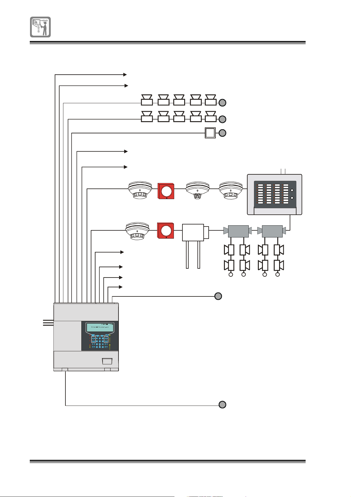
System 800 architecture
g
(
)
g
g
(
)
(
)
- Class chan
Loop end 1
Auxiliary contacts
External power supply
Sounder 1
Sounder 2
Configurable input
e / E xt. evac. / local fire input
Common Fire output (change over contacts)
Common Fault output (chan
e over contacts)
External
12V supply
Mains
supply
Loop end 2
Previou s Next
Esc
Fire
ABC DEF
Sound A larms
Fire Routing
Activa ted
1 2 3
GHI JKL
Silen ce A la rms
Fire Protection
Activa ted
4 5 6
PQR S TU V WX YZ
Delay
7 8 9
Pre- alarm
Verify
Select
Delay
0
Verificat io n
24V power output
RS485
RS232 for Printer
RS232 for Service PC or Printer
Not yet available
Printer not yet available
Fire routing equipment
Fault
Power
Reset
FAP-8 00
Syste m Fa ult
Power Fault
MNO
Cancel Buzzer
FRE Fa ult
Soun de r Fa ul t
Display Test
Fire alarm panel
Disablement
FunctionEdit
FRE Disablement
Soun de r Di sa bl em e n t
Test
Fixed Extin
uishing equipment
Not yet available
6
796688 (4188-657)_i2 _06/03
Page 7

Notes to the installer
The installer should follow the general requirements of:
BS5839:Part 1, the code of practice relating to the fire
detection and alarm systems for buildings.
The relevant parts of the BS7671 Requirements for
Electrical Installation, Institute of Electrical Engineers
Wiring Regulations 16th edition.
Second fix installation
Notes
To prevent the possibility of damage or dirt degrading the
performance or appearance of the System products, the
installation of second fix items, such as the
module
, should be delayed until all major building work in
electronic
the area is complete.
The installer should ensure:
Cables recommended in the manual are used for
wiring the system 800.
Cable gland is used for the mains supply cable.
Unused knockouts on an enclosure that have been
removed are not left open.
The wires between the cable termination point and
terminals are as short and straight as possible.
The cables of the system 800 and other systems are
separated by at least 160mm, unless dedicated
conduit / ducting is used.
No part of the building structure is used for earthing.
The cable length between the Repeat LED unit and
the respective detector, where used, does not exceed
10m. This length must be included in the total cable
length of the loop.
The ends of the mains flexible conductors terminated
in the product are crimped, using sleeved or insulated
crimp terminals.
Each mains powered control and indicating equipment
is supplied via a dedicated 2-pole fused spur unit that
is fed from a switch or protection device at the local
mains supply distribution board.
Mains power to the control and indicating equipment
is not supplied from an
IT Power System
.
796688 (4188-657)_i2 _06/03
7
Page 8
Earthing
Fixtures and fittings
The installer should acquire:
Site specific information from the interested parties
which must include details on the location of products
to be installed
The acquired information together with this manual
and the relevant standards should be used to assist
the work.
All earth connection points must be clean to provide good
electrical conductivity.
All earth leads and fittings provided must be installed
The loop cable screen must be continued through
each system device.
It is the installer’s responsibility to provide:
Adequate fixtures and fittings for the type of
construction surface onto which a product is to be
installed
As an aid to this decision, the weight and overall size
of each full assembly together with implications on
cable entries and routing should be taken into
consideration.
These procedures assume that the installer
provides cable glands, steel BESA boxes and
related items.
8
796688 (4188-657)_i2 _06/03
Page 9
Cables
EMC approved cables suitable for wiring the system:
Mineral insulated cable (MICC) to BS6207:Part 1
Delta Crompton FTZ2E1.5 FIRETUF OHLS fire
resistant data cable
Raydex CDT FG950
Cavicel SpA FIRECEL SR 114
distributed by Cables Britain
AEI Cables FIRETEC
BICC Pyrotenax FLAMESIL FRC
Datwyler LIFELINE
It is NOT permissible to run outgoing and return
pairs in a multi core cable, due to inadequate
separation and possible electrical interference
problems.
Panel installation
Inspect the contents
Before starting installation work check the package
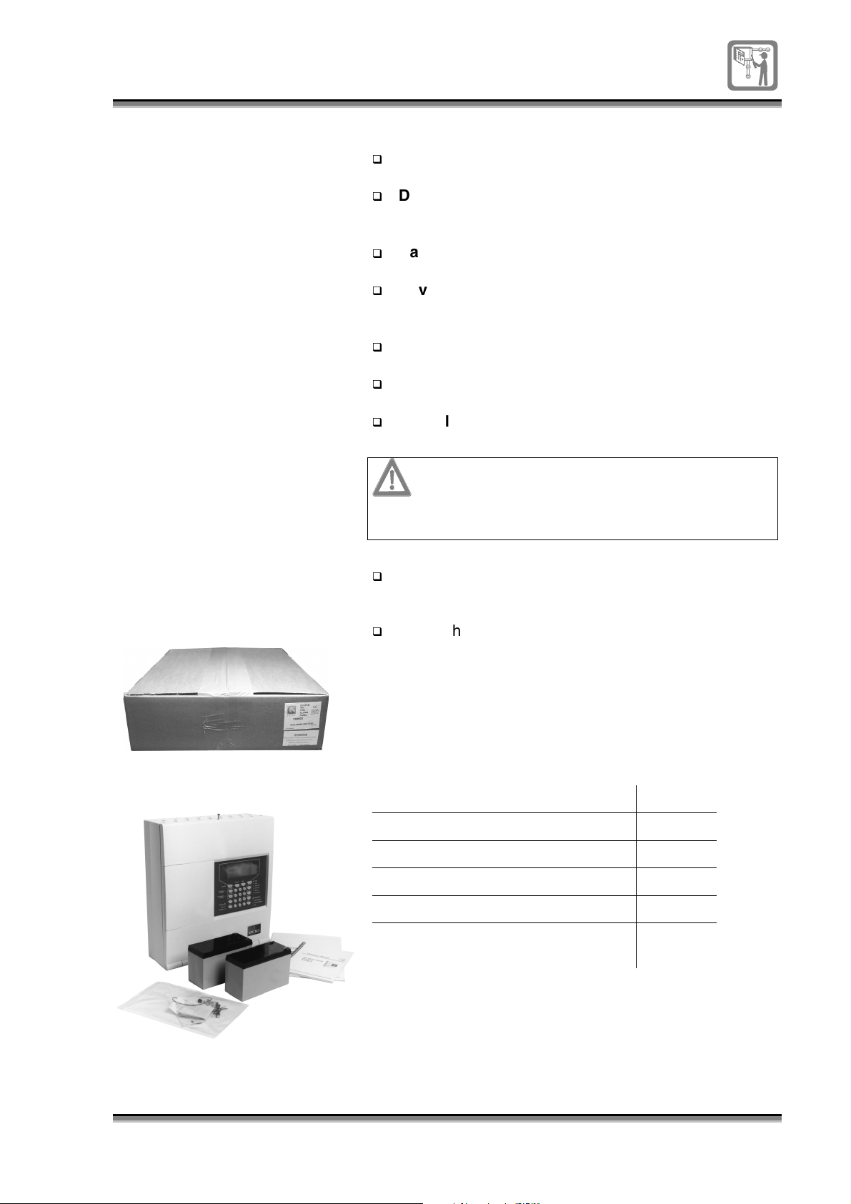
label and the contents of the package.
Check the contents, there should be:
-
System 800 fire alarm panel
-
2 - Battery 12V 7Ah
-
Spares pack
-
Panel wall mounting template
-
Instructions
Content of the spares pack:
Parts Quantity
Allen Key (door) 1
End-of-line resistor - 10K ohms 4
End-of-line label 2
Battery link 1
Spare 3.15A (T) fuse ceramic type
2
for mains & battery supply
796688 (4188-657)_i2 _06/03
9
Page 10
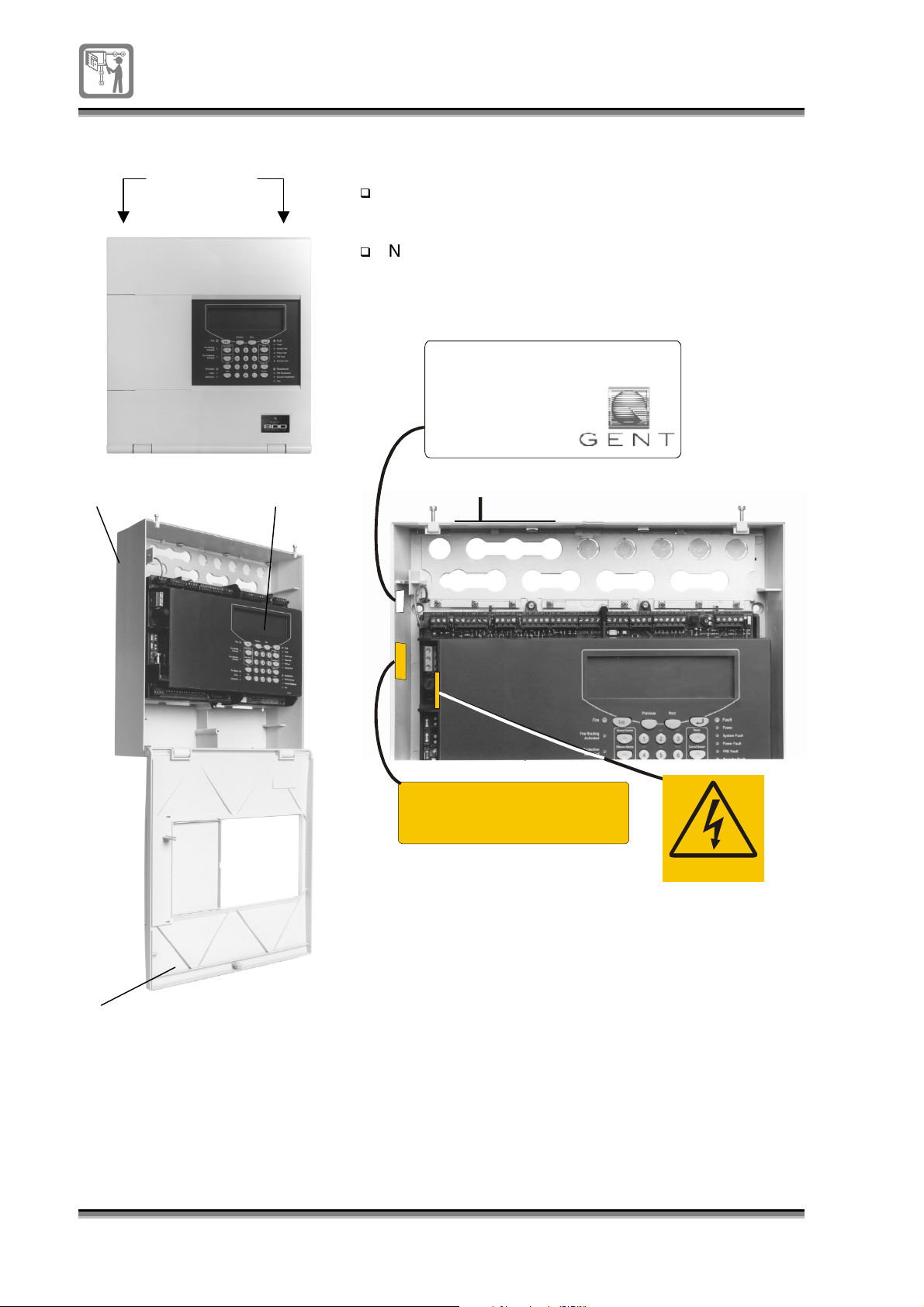
To open the panel door
Fixing screws
The panel
door
can be opened using the
allen key
supplied in the spares pack.
Partially open the two
fixing screws
and then hinge
open the panel door.
Note the information on the panel and labels inside
the enclosure.
Product : S YSTEM 800
Rated Voltage: 230v a.c.
Rated Current: 0.3A
Rated Frequency: 50Hz
Mains Fuse FS7: 3.15A (T)
Manu fac D ate xx/xx/xx
LXXXX-X
Backbox Electronic module
OPENING THE DOOR EXPOSES LIVE PARTS
CAUTION
HAZARDOUS VOLTAGE REMAINS
AFTER OPERATION OF FUSE
Danger
Door
10
796688 (4188-657)_i2 _06/03
Page 11
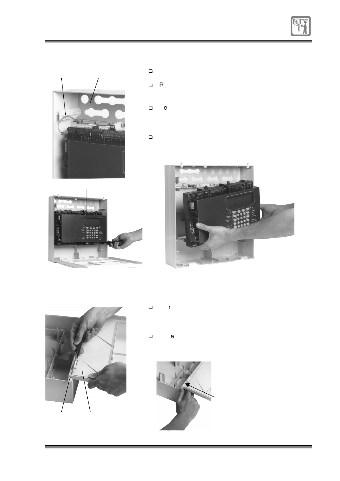
To remove and refit the
electronic module
Earth lead Gland plate
The
electronic module
should be removed from the
to prevent building dust getting into the module.
Remove the
Remove the five fixing screws that are used to secure
electronic module
the
earth lead
connected to the
to the
backbox
gland plate
.
backbox
.
Electronic module
Remove the
the
electronic module
electronic module
, earth lead and screws in a safe
from the
backbox.
place until required.
To refit the electronic module: follow the procedure in
reverse order.
Keep
To remove and refit the
panel door
Hinge pin Door
The
hinged door
backbox
to ease installation work.
To remove the door: Hold the door and use a terminal
on the panel may be removed from the
screwdriver to push out the two hinge pins, one at a
time.
To re-fit the door: Hold the
with the
hinge pins
slot visible insert the pin into the
door
to the
back box
assembly until it click fits into position.
Hinge pin slot must be visible
and
796688 (4188-657)_i2 _06/03
11
Page 12
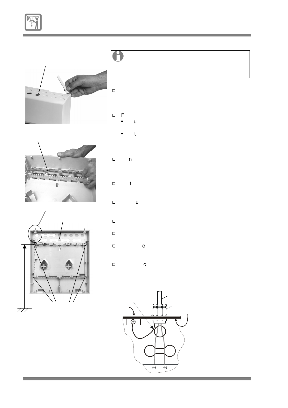
To mount the backbox
on wall
Cable entry points
Gland plate
Ensure there is at least 100mm clearance
around each side of the panel. Also there must
be sufficient space beneath the panel assembly
to allow the door to hang open.
Knockout the required cable entry points from the
backbox or where appropriate snap off the required
cable entry strips from the backbox.
For cable entry from top of enclosure:
Cut the
cable tie
and remove the gland plate from
the back face.
gland plate
Fit
enclosure, with
to the inside top face of the
earth terminals
towards the front of
the enclosure.
Mains cable entry points
Cable tie
1.7m
Fixing points
Floor level
Using the
panel wall fixing template
mark the four fixing
centres on the wall. Note the panel’s top fixing points
should be 1.7m above floor level to the top fixings.
Fix the
panel
to the wall surface using suitable fixtures
to support the full assembly.
Make use of all four fixing points when securing the
panel
to the wall.
Re-fit the
Fit the
Terminate all the external cables coming into the
door
to the
electronic module
backbox.
to the
back box.
at required cable entry points.
Mark the cables for connection to the appropriate
terminal block, see cables and wiring details.
Earth
drain
if part of
the cable
Backbox
Cable
Cable Gland
Glandplate
panel
Panel dimensions:
Height 375mm
Width 355mm
Depth 115mm
12
796688 (4188-657)_ I1.2 / 02.02
Page 13
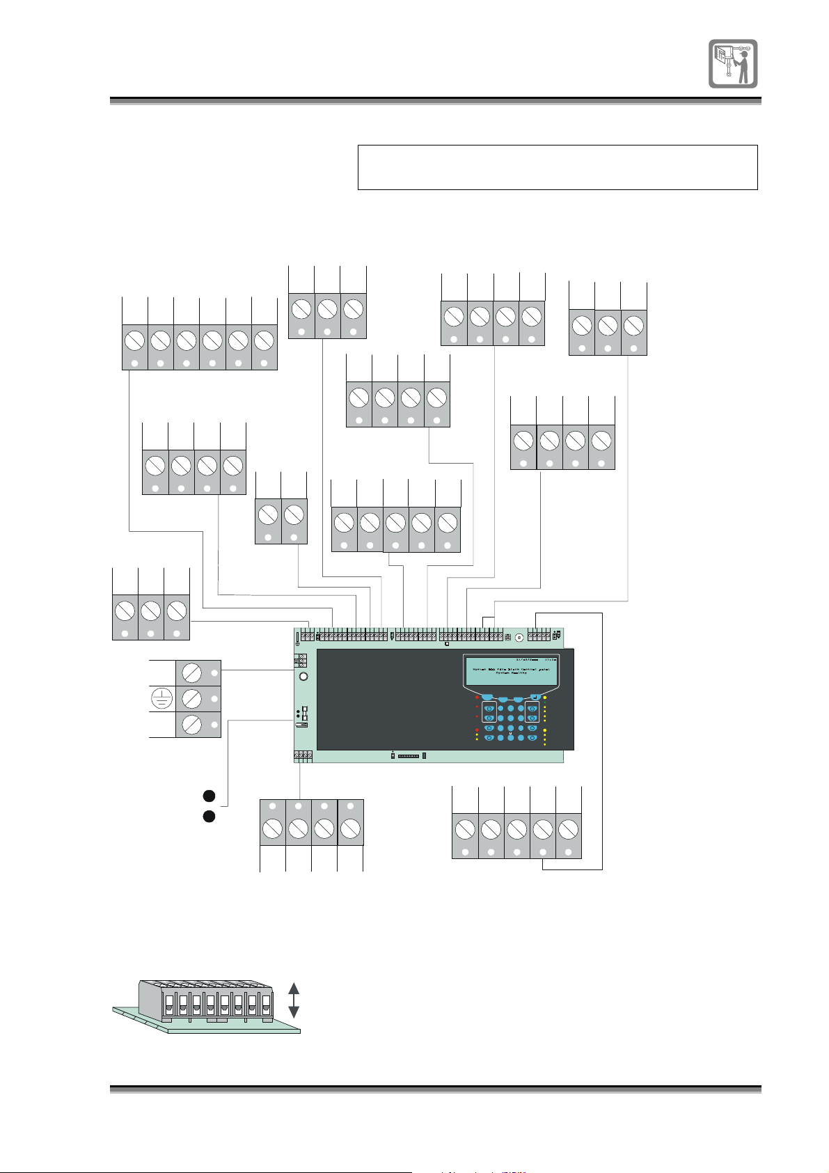
Connecting external circuits
Terminals
COMMON
EXT
PSU
+
-
EXT
MAIN
FLT
+
EXT
BAT
FLT
0V+0V
NC
FIRE
NO
C
TIP
To ease wiring, the terminal blocks can be
removed from the electronic module.
AUX DC
SUPPLY
24V
24V
0V
0V
RS232
TX
RX 0V
P21
SNDR1 SNDR2
S1+ S1-
P26
AUX
NC NO
P16
L
N
C
S2+
P3
FAP
7Ah
+
-
P8
S2-
CLASS
CHANGE
CC
0V
P14
P35
L
N
BZM
7Ah
+
-
P8
P17
CNO0V
FIXED EXT
NCNO
P16
P3
3.15A
P36
C+-+
1
2
3
P21
FS7
FS3
5
SW2
I/P
P17
LOOP
L1 L20V0V
P4
P20
COMMON
FAULT
NC
NO
C
I/P
0V
P15
S1+S1- S2+
0V+0V
S2-
0v N OCC NC
C
P12
1
2
3
P26
P14
P1
1
P19
2
3
24V
L1 L20V 0VNONC I/PC0V
0V
0V
24V
0V TX
AB+V
P15
P20 P4
C128
P7
Fire Protection
Fire Routing
Verification
TX RX0V
Fire
Activated
Activated
Pre-alarm
Delay
ELECTRONIC MODULE
I/P
P5
Esc
Sound Alarms
Silence Alar ms
Delay
Verify
0V
RX0V
P2
AB
P7
LCD
PC
I/P
CONTRAST
LINK
P6
P18
Previous Next
ABC
DEF
1
2 3
GHI JKL MNO
Cancel Buzzer
4 5 6
PQRS TUV
WXYZ
Displa y Test
7 8 9
Edit
Select
Function
0
C
RS485
0V C N O
NC
1
1
2
2
3
3
P23 P22
Fault
Power
Reset
System Fa ult
Power Fault
FRE Fault
Sounder Fault
DIsablement
FRE Disablement
Sounder Disablement
Test
NO
NC
P5/P2
+V
0V
CNO0V
FIXED EXT
Removable terminals
rem ovablerem ovable
I/P
P18
To ease installation the terminal blocks on the
module
the
can be unplugged from the board, the exception is
mains
terminal block, which is fixed and cannot be
removed from the board.
796688 (4188-657)_I1.2 / 02.02
electronic
13
Page 14
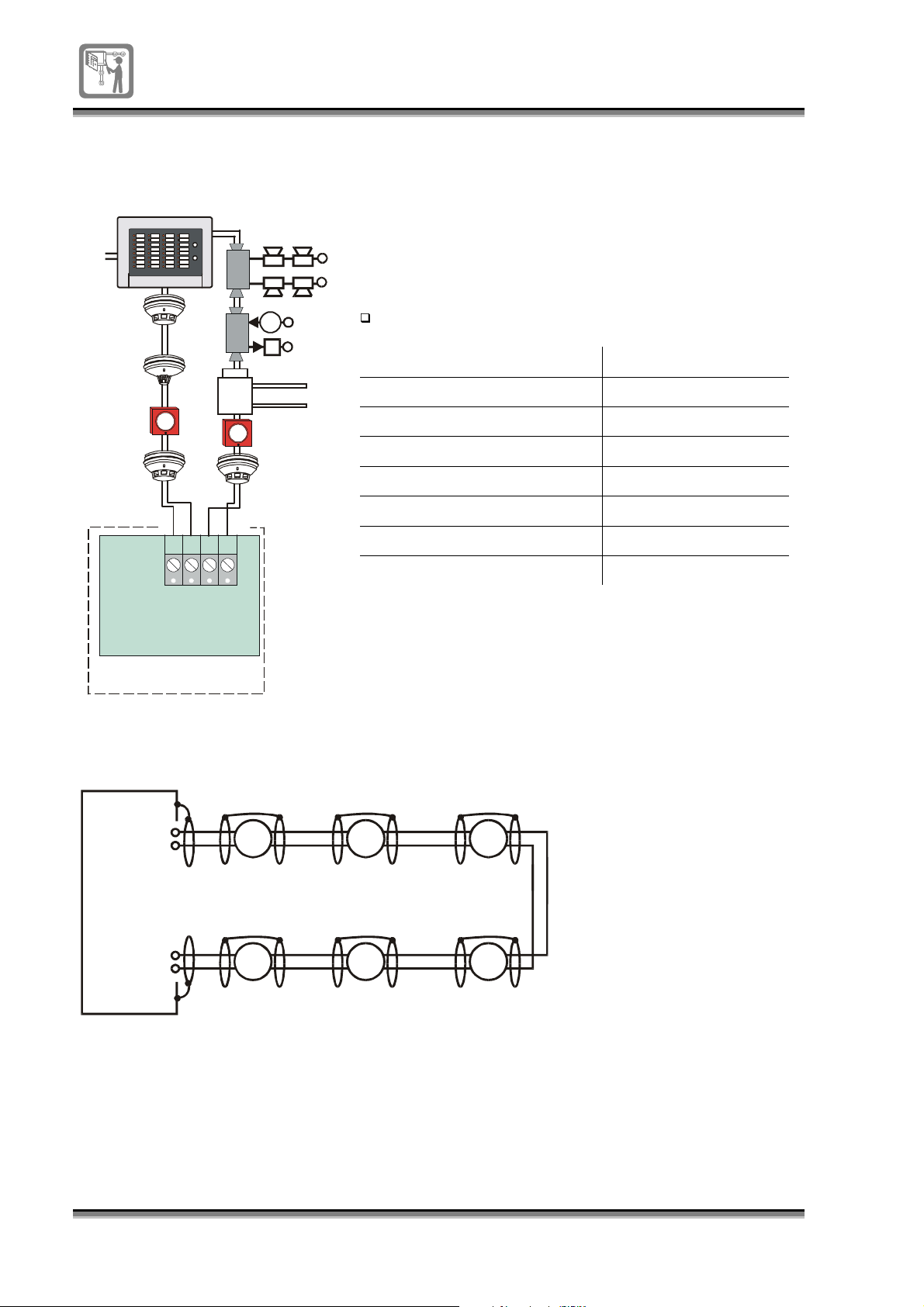
External circuits
Loop circuit
12V
Zonal
repeat
Loop end 1 Loop end 2
L1 L20V 0V
LOOP
P20
Electronic
Module
Sounder Control
Transponder
Single
Input
or
Output
The loop circuit of a system 800 can accommodate 127
devices, such as conventional detectors fitted to
addressable bases, manual call points, zonal indicator
units and sounder control transponders.
Data:
Loop length 1Km
Equipment Quiescent current
Ionisation smoke 30µA
Optical smoke 60µA
Heat 20µA
Rate of Rise 20µA
Detector base 50µA
Manual Call Point 45µA
Control panel 50mA
Control panel
Loop earth continuity
CONTROL
PANEL
Loop
Circuit
L1
0V
L2
0V
Earth continuity
The cable earth (screen) must
be continued through each
device on the loop circuit and
to a panel earth point on the
gland plate.
14
796688 (4188-657)_ I1.2 / 02.02
Page 15
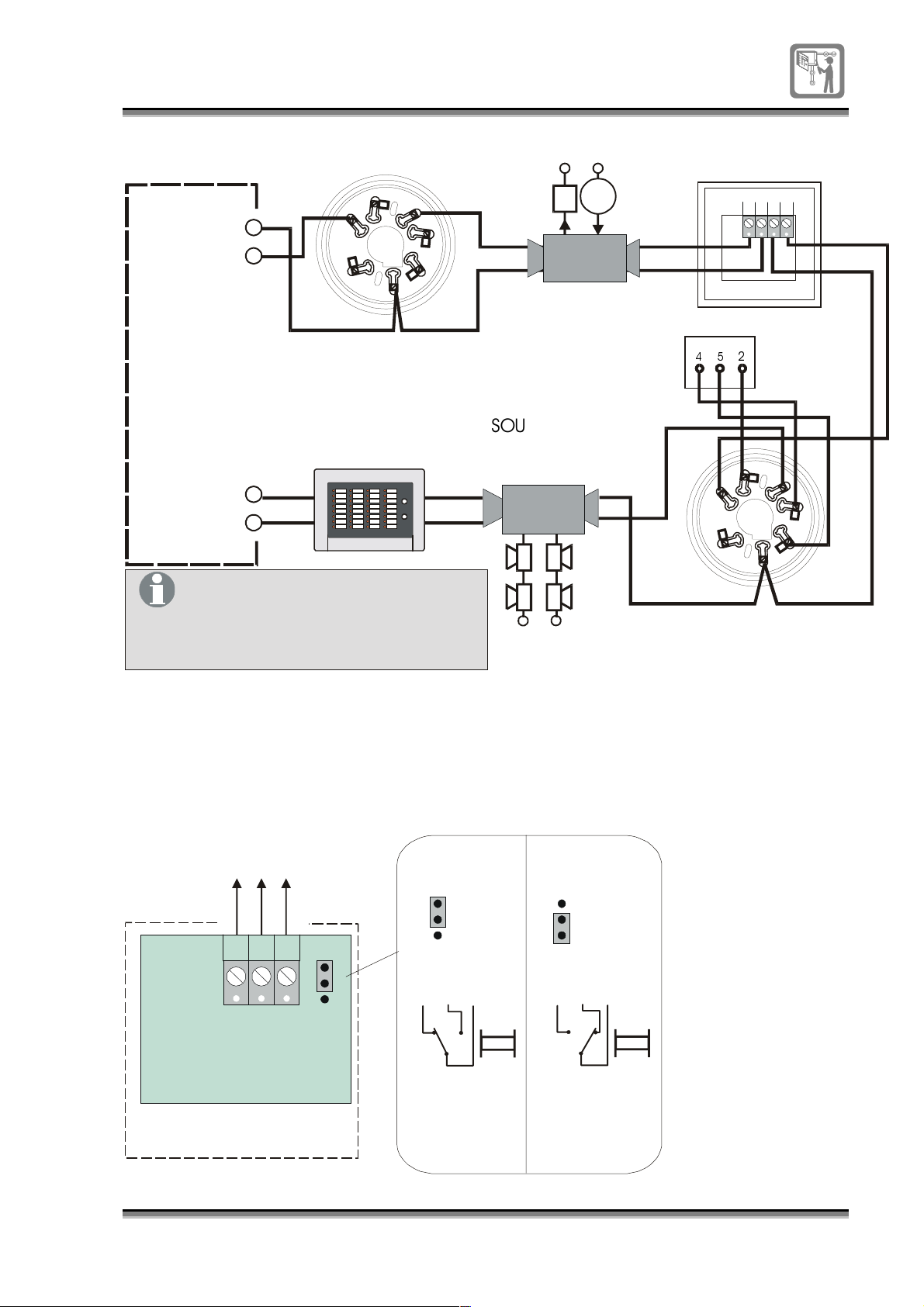
Loop device wiring
g
g
g
&21752/
3$1( /
Loop
Circuit
,IWKHODVWGHYLFHLVDGHWHFWRUEDVH
WKHQLWVQXPEHUWHUPLQDOPXVWEH
ZLUHFRQQHFWHGWR9RI(QGRQ
WKHFRQWUROSDQHO
L1
0V
L2
0V
2
1
7
6
$''5(66$%/(%$6(
=21$/
5(3($7
75$16321'(5
+UL
-OUT
IN OU T
+UL
-UL
+UL
3
4
5
+UL
-IN
+UL
-OUT
-UL
6LQJOH
,QSXW2XWSXW
0&3
7UDQVSRQGHU
/('
PRGXOH
6281'(5
&21752/
75$16321'(5
+UL
-IN
+UL
-OUT
+UL
-IN
2
3
1
5
7
6
$''5(66$%/(%$6(
ZLWK/('PRGXOHFRQQHFWHG
4
Common fire output
Common fire output via
chan
e over contacts
rated 2A @ 30V maximum
NC
NO
C
COMMON
FIRE
P14
Electronic
Module
Control panel
1
2
3
P12
The system 800 panel provides a common fire output via
change over contacts rated 2A @ 30V. A fire relay
operates the change over contacts. Setting a hardware
link for normally energised or de-energised state can
configure the relay operation.
Factory
default
1
2
3
P12
NC
NO
C
Normal condition
the re lay is
de-ener
ise d
1
2
3
P12
NC
NO
C
Normal condition
the re lay is
ener
ise d
796688 (4188-657)_I1.2 / 02.02
15
Page 16
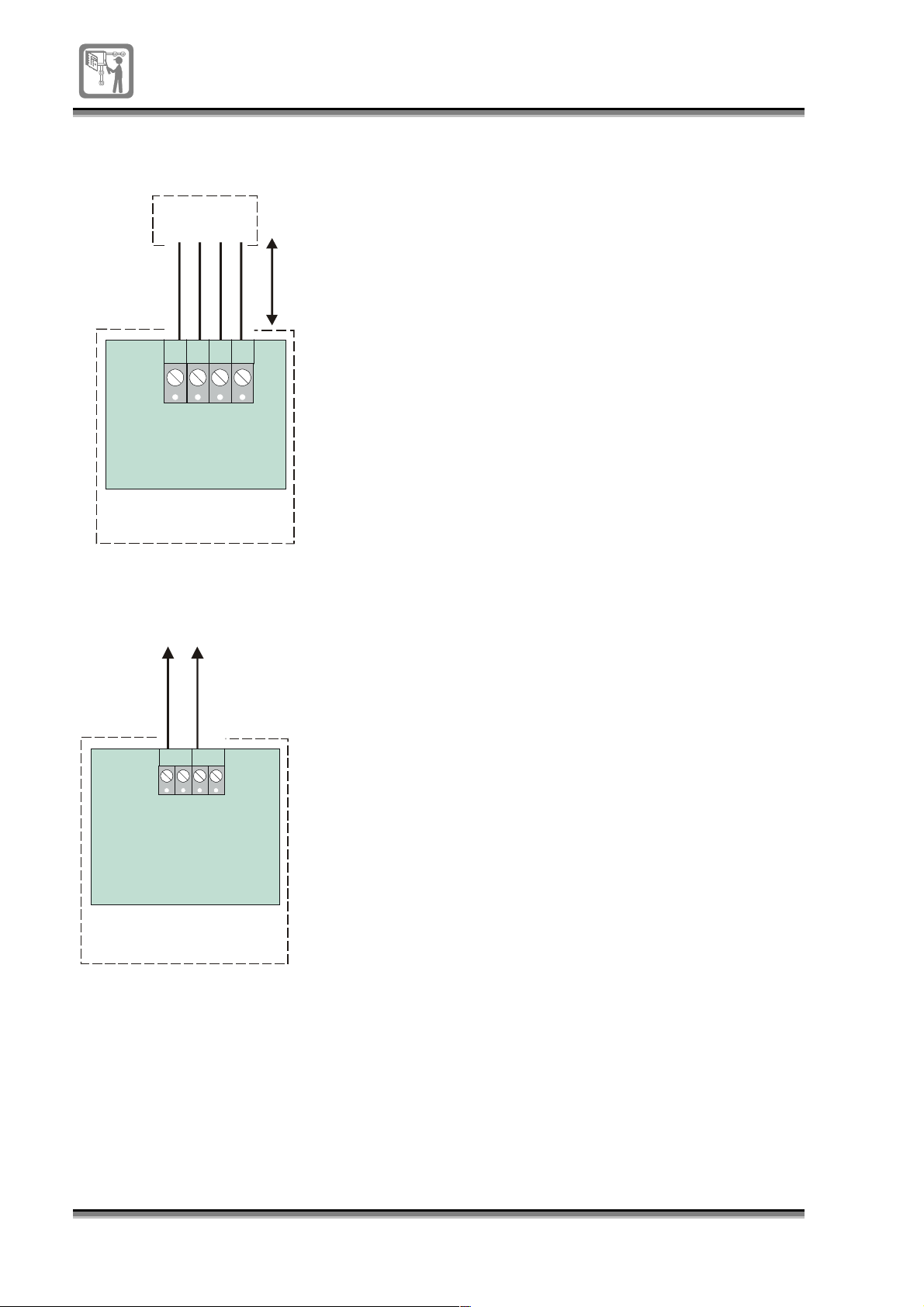
Repeat panel connection
This facility is n ot ye t availab le
Dedicated
Repeat panel
1Km
maximum
cable
distance
The system 800 panel can accept connection of up to two
dedicated repeat panels using the RS485 terminals.
AB
RS485
P7
0V
+V
Electronic
Module
Control panel
24V Power output
24V 0.5A maximum output
24V 0V
The system 800 panel has a 24V-supply output to supply
power to external equipment. The output will supply 24V
at 0.5A maximum.
16
P4
AUX DC SUPPLY
Electronic
Module
Control panel
796688 (4188-657)_ I1.2 / 02.02
Page 17
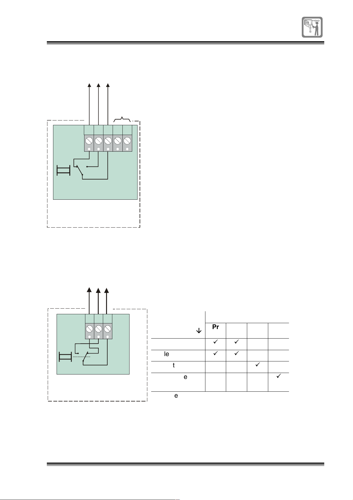
Common fault output
g
g
g
g
g
Common fault output via
chan
e over contacts
rated 2A @ 30V maximum
Not used
NC
COMMON
FAULT
P15
NO
I/P
C
0V
Electronic
Module
Control panel
The system 800 panel has a common output that
operates when the panel goes into a fault condition. The
contacts are shown in their normally energised position
and are rated 2A at 30V maximum. The contacts can be
used to switch external equipment on occurrence of a
fault via the voltage free contacts. The fault output can be
controlled using the fault routing facility.
Contacts shown with the relay
normally ener
operatin
ised, this is the normal
state.
Auxiliary relay output
Auxiliary rela y o utput
via volta
Factory default: Auxiliary relay w ill
ener
with system reset
e free contacts
Electronic
Module
ise with a fire event a nd is reset
NC NO
C
P16
AUX
Control panel
The system 800 panel has an auxiliary relay that can
operate when a fire event is detected in the system
(default setting). The relay contacts are rated 2A @ 30V
maximum. This output can be used to signal external
equipment in the event of a fire in the system. The relay is
is automatically reset with the following settings:
Common
Relay resets
with
System reset
Silence Alarms
Fault removed
Disablement
Pr Fi Fa Di
È
È
99
99
9
9
removed
Pr – prealarm
Fi – Fire
Fa - Fault
Di - Disablement
In addition to the fire mode of operation, it is possible to
configure the relay to operate with a prefire, fault or
disablement conditions.
796688 (4188-657)_I1.2 / 02.02
17
Page 18
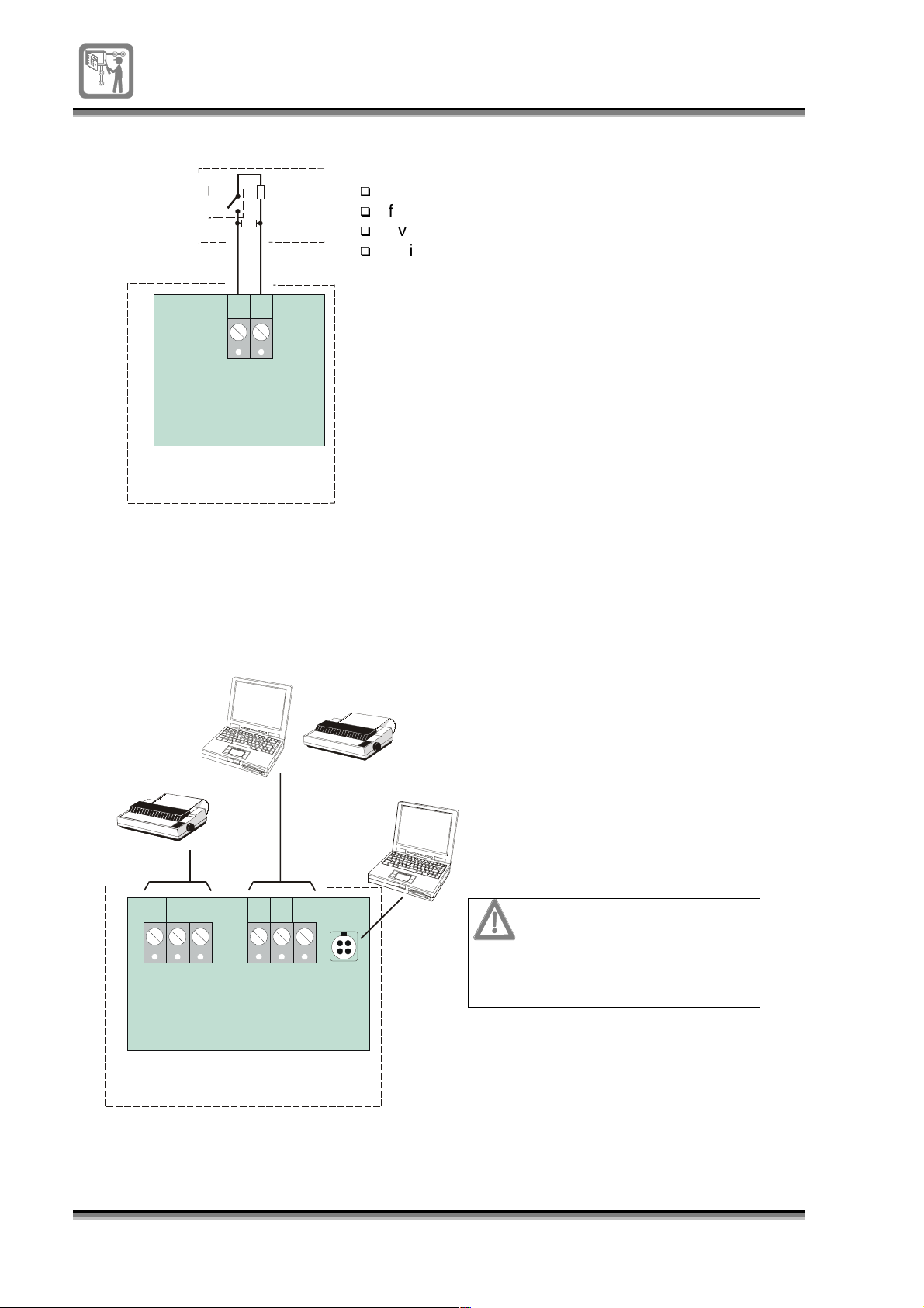
Local input
g
y
g
g
Local Input
(ie Class Chan
operated b
a pro
ram mer)
CHANGE
e
CLASS
The system 800 panel has a local input that can be
configured as a:
class change
10K
CC
10K
0V
fire input
evacuate input
switched OFF
class change
As a
input the system alarm sounders are
used for class change application, such as in an
educational establishment like school or college.
P14
As a
the panel interprets this as a fire event
fire input
and the panel goes into fire condition. The alarm
Electronic
Module
sounders in the system operate as per a fire event from a
device on the loop.
Control panel
The local Input can be configured as a
Class Chan
e, Fire or Evacuate input.
RS232 interface
or
Service PC
(Not yet available)
Printer
As an
alarms signal and operates the alarm sounders in the
system.
Additionally the local input can be enabled or disabled
using the menu controls at the panel.
If configured as a fire input the panel can put the input
into a Test State.
Printer
(Not yet available)
Service PC
evacuate input
The system 800 panel has a RS232
interface which can be used to connect the
service PC during commissioning, for
labelling devices and zones in the system.
The RS232 will facilitate the connection of
a printer for printing system events; this is
not yet available.
the panel interprets this as a sound
RX 0V
TX
RS232
P5
Terminals P2 and P6
share a dedicated RS232
which can be connected
to e ither a S ervice PC or Printer
18
796688 (4188-657)_ I1.2 / 02.02
RX 0V
TX
RS232
P2
Control panel
PC
LINK
P6
Electronic
Module
The terminal block P2 and
connector P6 share a
dedicated RS232 and only
one of these can be used at
any one time.
Page 19

Fire routing equipment
(
)
(
)
gg
g
(
)
gg
0 -10K resistance
confirmation
output
Coil resistance
650R
nominal
Auto-dialler equipment
Such as Digicom
or Red Care
The system 800 panel can activate fire
routing equipment, such as an auto
dialer in the event of a fire condition in
the system. The panel can be
configured to output either a voltage free
signal or a 24V output to trigger the
external equipment.
Activation
confirmation
inp ut
I/P
0V C NO NC
P18
0 -10K resistance
confirmation
output
Activation
confirmation
inp ut
Activation
ou tput to tri
+24V
0V
auto dialer
1
2
3
P23
Electronic
Module
Control panel
Auto-dialler equipment
Such as Digicom
or Red Care
Voltage free activation
ou tput to tri
auto dialler
1
2
3
P22
er
Factory de fau lt
link settin
er
Using the menu controls at the panel the
fire routing equipment operation can be:
Manually activated or de-activated
s
Output can be enabled or disabled
A delay of up to 10 minutes can be
set up before automatic output action
The monitoring of the output can be
enabled or disabled.
0V C NO NC
I/P
P18
1
2
3
P23
Electronic
Control panel
1
2
3
P22
Module
796688 (4188-657)_I1.2 / 02.02
19
Page 20
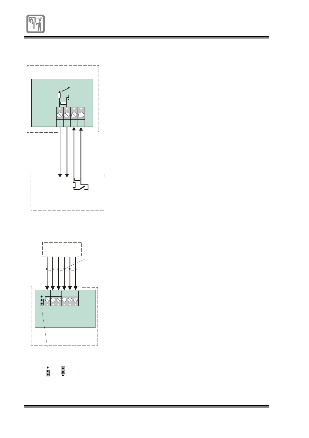
Fire protection
y
y
equipment
Control panel
Electronic
680R
3k3
FIXED EXT
(This facility is not yet available)
The system 800 panel has a fire protection equipment
output to trigger fixed extinguishing equipment.
Module
P17
CNO0V
3k3
3k3
I/P
Activate
FPE
680R
Activated signal
from F PE
Fixed Protection Equipment (FPE)
External power supply
for alarm sounders
M ain s fa ilure inpu t
Monitors
clean contacts
of external power
supply
Battery failure inp ut
Monitors
clean contacts
of external power
supply
Power
fro m ex ternal
24V power
suppl
External PSU
The system alarm sounders can be configured to operate
from the on board power supply or an external power
supply, by setting a link on the electronic module.
The panel is able to monitor the condition of the battery
and mains supply of the external power supply unit via
clean contacts. A closed clean contact at the power
supply equipment is a fault signal to the control panel.
P36
1
2
3
S election link for
intern al / ex tern al
power suppl
20
+-+
EXT
PSU
P21
P36
1
2
3
Intern al
PSU
(Fa ctory
default)
0V
EXT
MAIN
P36
1
2
3
External
PSU
+
EXT
BAT
0V
Electronic
Module
Co ntrol pan el
796688 (4188-657)_ I1.2 / 02.02
Page 21
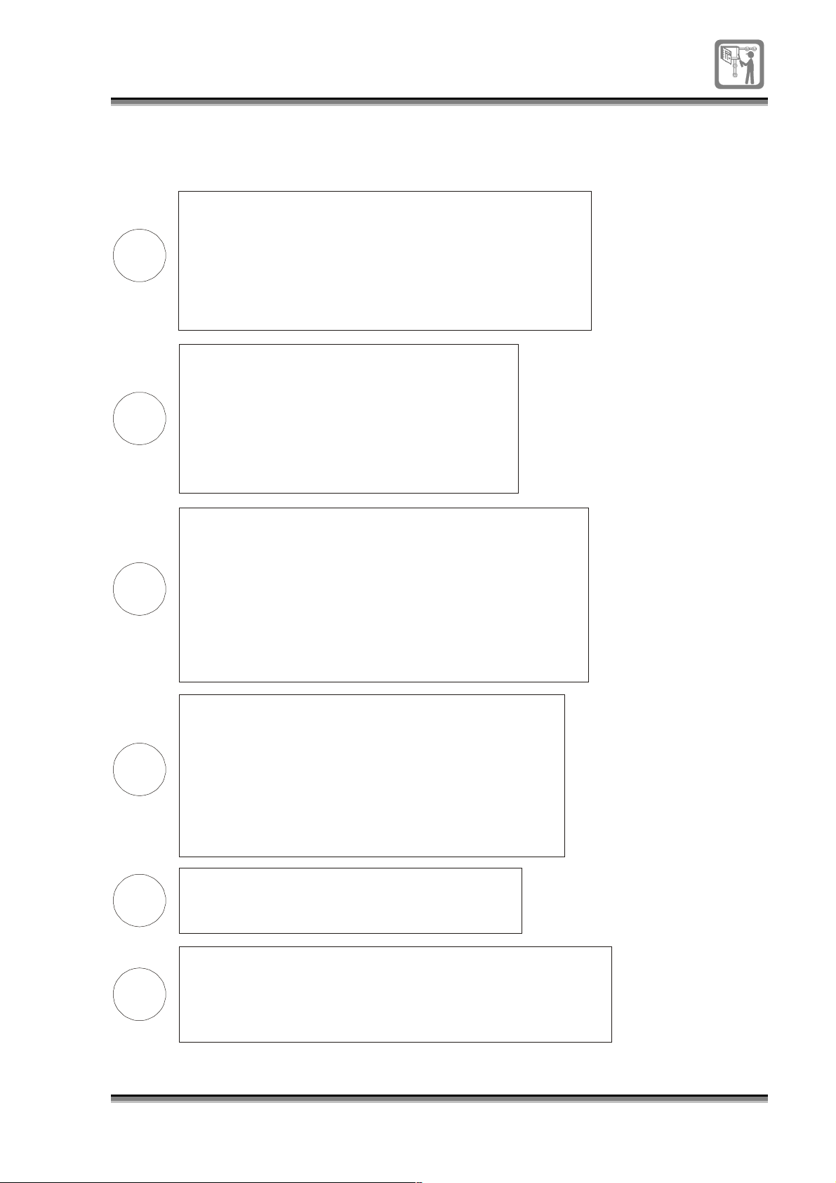
Commissioning
y
y
y
g
y
y
y
g
y
y
y
y
g
g
g
g
g
y
g
y
process
Without any power applied to the panel:
the continuity of the loop circuit wiring,
1. Verif
The cable resistance should be 13ohms max. at 1Km.
DO NOT UNDERTAKE HIGH VOLTAGE TESTS WITH WIRING
CONNECTED TO THE LOOP DEVICES, SUCH AS TO THE BASE.
2. Verif
W ith circuit connected the 10Kohm s end-of-line
resistance can be measured.
Connect the mains and battery supply to th e
panel and once powered up:
1. Carr
and check all the indicators are workin
2. Setup the s
3. Carr
o f b atter
and check fault indications are
Connect the loop circuit:
1. Check the address allocation with onl
note a loop open circuit fault is displa
Repeat the test with onl
with both ends connected.
2. Carr
of the loop circuit, re-allocate the loop after each test.
3. Re allocate the loop, confi
to be saved at the panel and save the loop map data to the
panel EEPROM.
the continuity of the sounder circuit wiring.
out a Display test accessible at access level 2
.
stem clock, accessible at access level 3.
out temporary disconnection and re-connection
, mains supply and sounder circuits
iven of disconnections.
loop end-1 connected,
ed.
loop end-2 connected and then
out open circuit and short circuit tests on the +ve and -ve lines
ure the Hardware link to allow data
Configuration:
1. Assi
2. Label devices and zones.
3. Connect, confi
connected to the panel.
4. On completion of chan
data saved to the EEPROM, reset the hardware
link to position 2-3 to write protect the EEPROM.
Fire plan:
1. Test the fire plan.
2. Check alarm sound levels in all areas of the buildin
Handover:
1. Ensure all interested parties are informed the fire alarm
s
2. Fill in the lo
and the need to maintain the system in accordance with BS5839:Part 1.
n devices to zones
ure and test other equipment
es to configuration data and with
(s).
stem is active.
book and provide advise on user responsibilit
796688 (4188-657)_i2 _06/03
21
Page 22
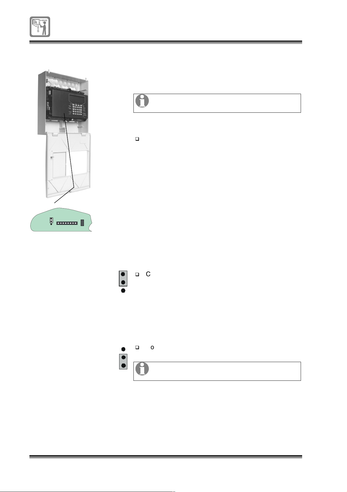
Hardware link
On making changes to the panel set up the modified
entries must be saved to the EEPROM located inside the
panel. To allow the changed data to be saved to the
EEPROM, a hardware link must first be configured.
A trained engineer must carry out any changes
to the system configuration.
Electronic module
P1
1
P19
2
3
EEPROM
enable
C128
To allow data to be saved to
EEPROM
P1
1
2
3
EEPROM
enable
Open the panel door using the
allen key
supplied in
the spares pack.
The hardware link is located mid-way on the bottom
face of the electronic module.
Configure the link to position 1-2.
To write protect EEPROM
22
796688 (4188-657)_i2 _06/03
EEPROM
enable
1
2
3
P1
Configure the link to position 2-3.
Always leave the EEPROM link in the protected
position after saving data.
Page 23
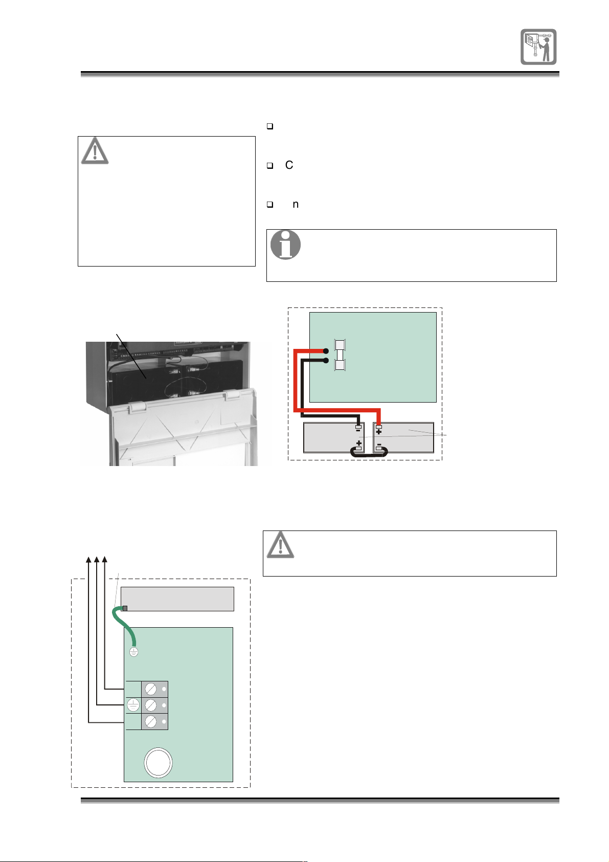
Power up
Battery connection
CAUTION: RISK OF
EXPLOSION IF
BATTERY IS REPLACED
BY AN INCORRECT
TYPE.
DISPOSE OF USED
BATTERIES
ACCORDING TO THE
INSTRUCTIONS.
To power up the panel connect the mains and battery
supply.
Fit the batteries in to the panel, observing the location
and orientation of battery installation.
Connect the wires from the
electronic module
to both
the batteries.
Ensure the battery link is fitted.
The panel will not power up on battery supply
alone. However in the event of mains failure the
battery will maintain a standby supply to the
panel.
Control panel
Battery
Mains supply connection
Mains
Supply
230V
Earth to gland plate
P3
L
Control panel
Gland
Plate
Electronic
Module
FAP
7Ah
+
-
P8
FS3
Electronic
Module
2 X 12V 7Ah
BATTERY
To prevent serious injury, ensure the mains
supply to the control panel is isolated until
required.
A qualified person in accordance with the current
regulations must make the mains supply connection to
the control panel. The mains to the panel must be via a
dedicated 3A fused spur unit, marked in red FIRE ALARM
– DO NOT SWITCH OFF.
N
FS7
Mains fuse
3.15A
796688 (4188-657)_i2 _06/03
23
Page 24
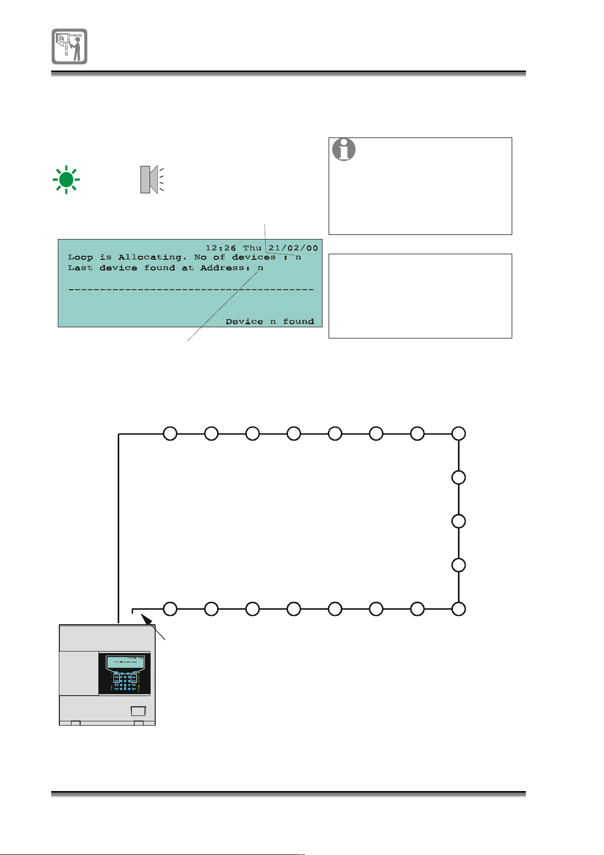
Power up indications
g
and address allocation
Power
The number of devices
allocated
The last device found durin
allocation
On powering up the panel the display shows messages of
address allocation and the power on indicator is lit.
The allocation process
starts automatically and
thereafter the fire
detection. The loop is fully
operational and requires no
manual intervention to start
fire detection.
Tip The sounder control
transponder faults are
latching faults and will
require a panel reset to
remove the fault at the
transponder.
LOOP
CIRCUIT
END 1
Fire
Fire Rou ting
Activated
Fire Protection
Activated
Pre-alarm
Delay
Verification
Allocation process
123
19 18 17 16 15 14 13
NOTE: END 2 CONNECTION IS NOT
Previous Next
Esct
Fault
Power
ABC
DEF
Sound Alarms
Reset
System Fault
2 3
1
Power Fault
GHI JKL MNO
Cancel Buzzer
Silence Alarms
FRE Fault
4 5 6
Sounder Fault
PQRS TUV WXYZ
Display Test
Delay
7 8 9
Disablement
FunctionEdit
Verify
Select
FRE Disablement
0
Sounder Disablement
Test
MADE ON FIRST POWER UP.
The addresses are allocated to each device on the loop
starting from End 1, in a numerical order, to End 2.
4
56
7
8
9
10
11
12
CONTROL PANEL
24
796688 (4188-657)_i2 _06/03
Page 25
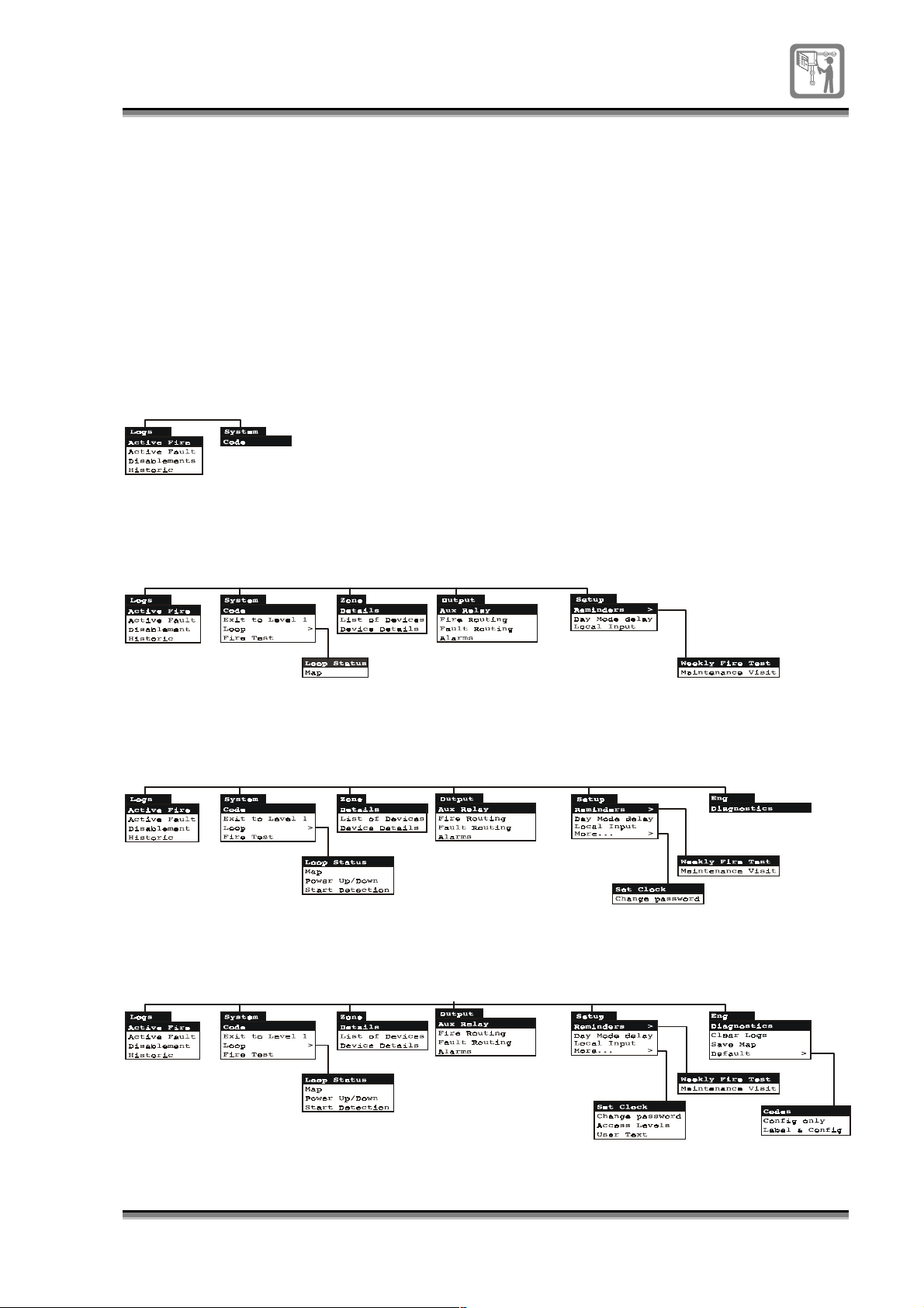
Menu map and access
g
y
g
levels
Access level 1 = General mode
Access level 2 = Security mode
Access level 3 = Customer mode
The menu map below shows the functionality available to
the user at various access levels.
To gain access to the panel controls and menu options,
the user must enter the appropriate code for the desired
access level.
Access level 4 = Engineering
mode
A2m in, A3min and A4min signify minimum
access level required for the operation.
Menu map at A1 Access level 1 (No code required)
At this level access is available to the
operation and if confi
ured the can also operated.
system logs, coded entry to other levels, cancel buzzer
display test
Menu map at A2 Access level 2 (Code 2222)
This leve l is for sec urity personal.
Menu Map at A3 Access level 3 (3333)
This level is for customer's technician responsible for the s
stem.
Menu Map at A4 Access level 4 (4444)
This leve l is for en
ineering use only.
At this level the loop is disabled and events are not detected.
796688 (4188-657)_i2 _06/03
25
Page 26
Operating instructions
g
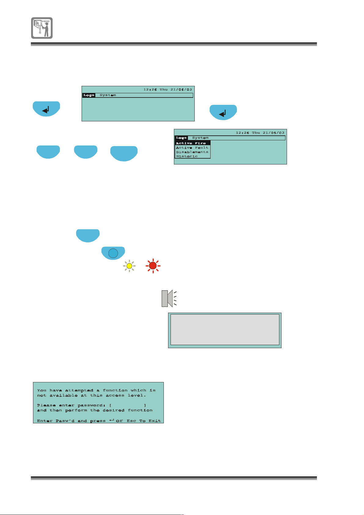
To select a menu option
Press to view
top level menu
Press to highlight option
Previous Next
Press to return to
previous menu level
Esc
Press to enter
a selection
To carry out a display test
(A coded entry may be required for this command)
NOTE: is not possible if the menu or a form is displayed.
A2 A1
Display test
or
if configured
Esc
Esc
Display Test
Display Test
All the LEDs illuminate
All the LEDs illuminate
for a short duration
for a short duration
Functions that are not accessible at an access level
If you select a function that is not accessible at the current access level
then you will
et the following message:
26
796688 (4188-657)_i2 _06/03
Page 27
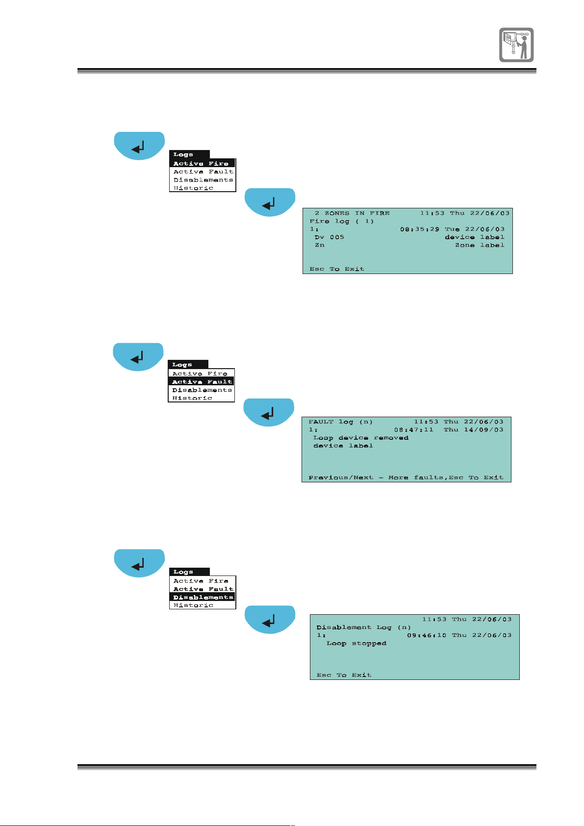
To view active Fire events
A1
To view active Fault events
A1
To view Disablements
A1
796688 (4188-657)_i2 _06/03
27
Page 28
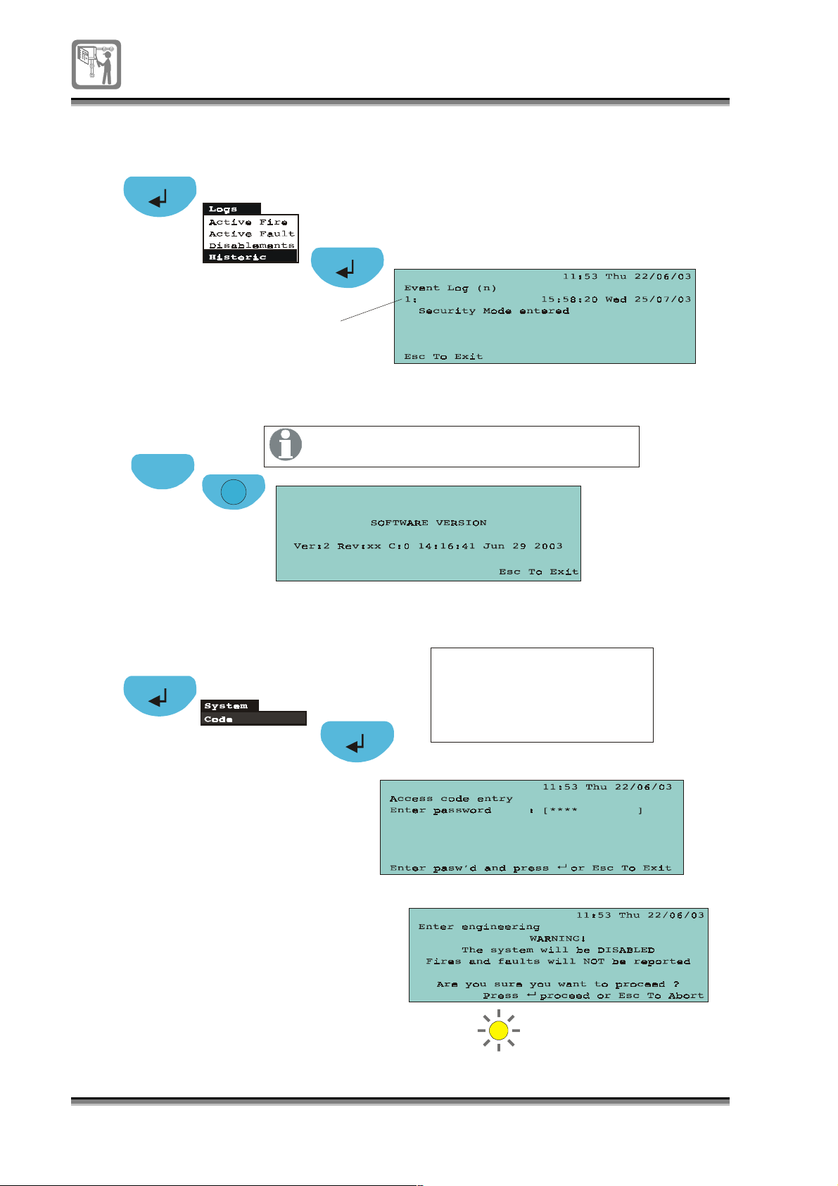
To view Historic events
A1
Event 1 - latest event
To view the software version
A3
Esc
To enter an access level (eg 2, 3 or 4)
Function
Viewing the software version is only possible
at access level 3, out of the menu mode.
A1
Enter the numerical password
Factory default codes are for:
Access level 1 : None
Access level 2 : 2222
Access level 3 : 3333
Access level 4 : 4444
28
796688 (4188-657)_i2 _06/03
For
A4
only
Disablement
Page 29
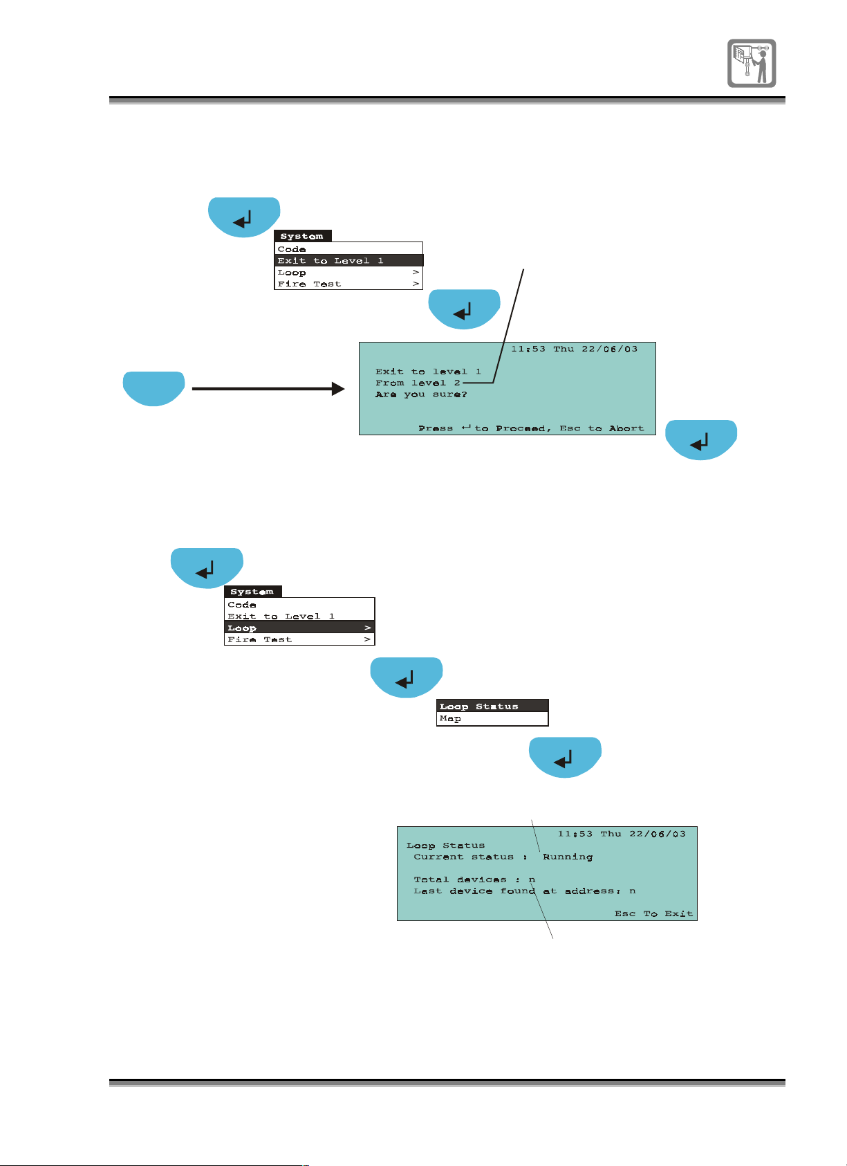
To exit to access level 1
g
A2, A3 or A4
Alternative m ethod
Esc
To view loop status
Can also be from level 3 or 4
A2
Current status of the loop is runnin
Number of
devices on
the loop
796688 (4188-657)_i2 _06/03
29
Page 30
To activate Delay Mode faciity
g
g
g
A2
Esc
Delay
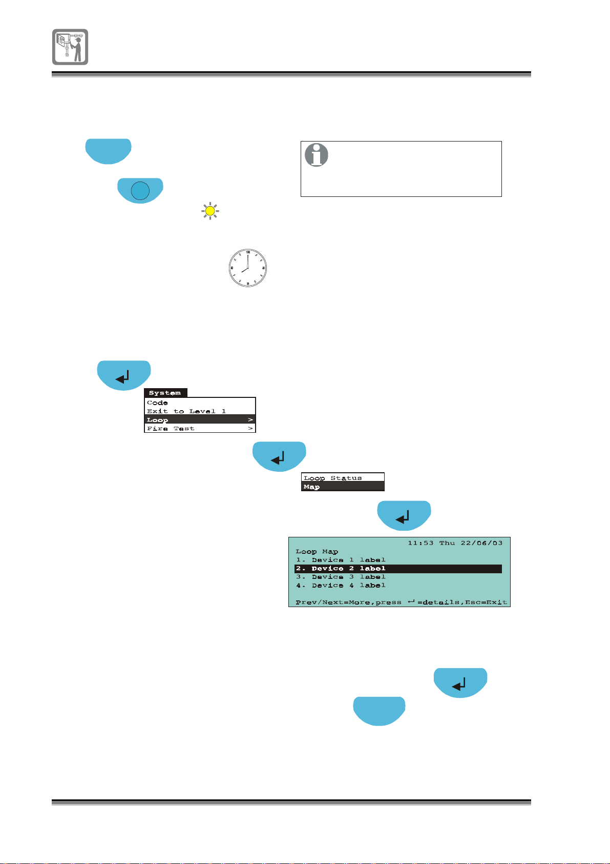
To view loop map
A2
Delay
The Delay function will only
operate if the Delay timeout
period was pre-confi
to a value
Delay Mode can be configured
to be active for up to 8 hours
ured
reater than 0 hours.
30
796688 (4188-657)_i2 _06/03
By pressing the Enter button on
a hi
hlighted device it is possible
to view device details,
see device details.
Press to return to loop map
Esc
Page 31
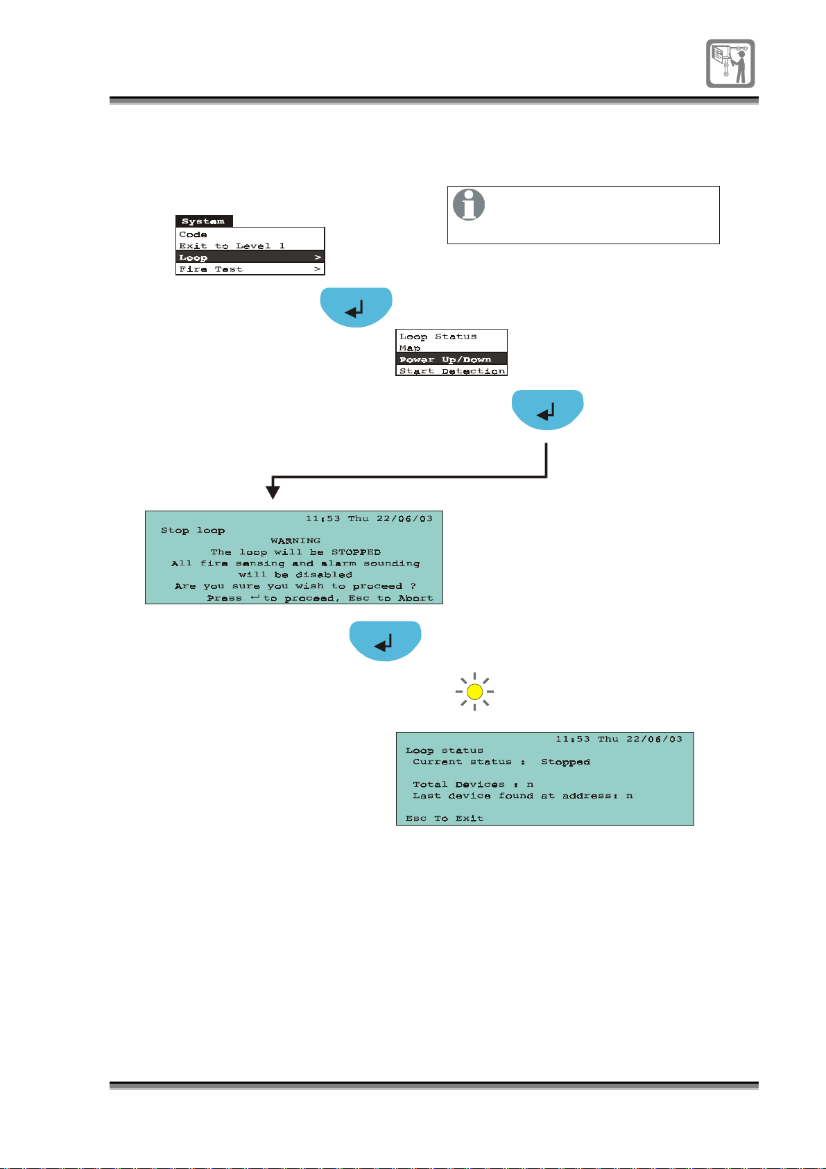
To power down the loop circuit
(assuming the loop is powered up)
A3
It is not possible to power down
the loop when the panel is in
fire condition or test mode.
Disablement
796688 (4188-657)_i2 _06/03
31
Page 32
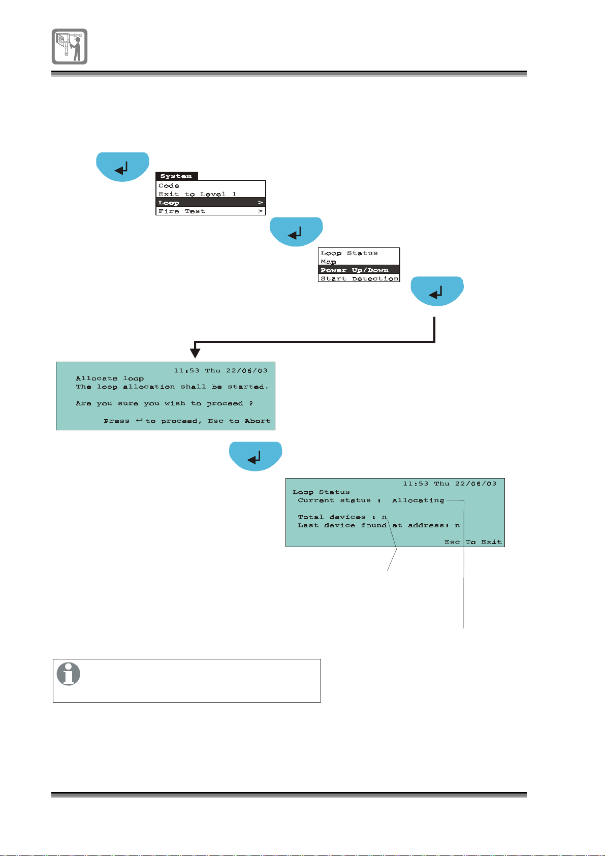
To power up the loop circuit
g
g
(assuming the loop is powered down)
A3
If the loop map has changed, only then
the loop detection process must be started
manually, see
32
796688 (4188-657)_i2 _06/03
This number will increment as devices are
allocated. The allocation process can
take several minutes
To start detection process.
‘Allocated’
‘Runnin
- if loop map has chan
’ - if no changes to the loop map
ed
Page 33
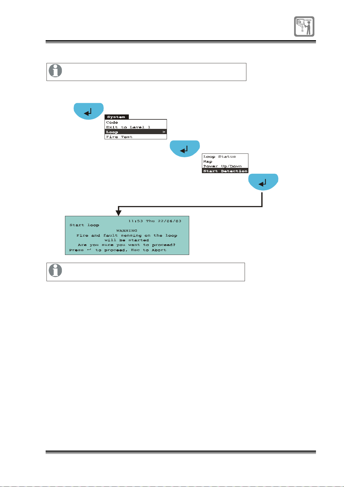
To start detection process on the powered up and allocated loop
If the loop map has changed on a manually powered up loop
then it is necessary to manually start the detection process.
A3
If the panel is at access level 4 the detection process will be
temporarily stopped until you exit to level 1, 2 or 3.
796688 (4188-657)_i2 _06/03
33
Page 34
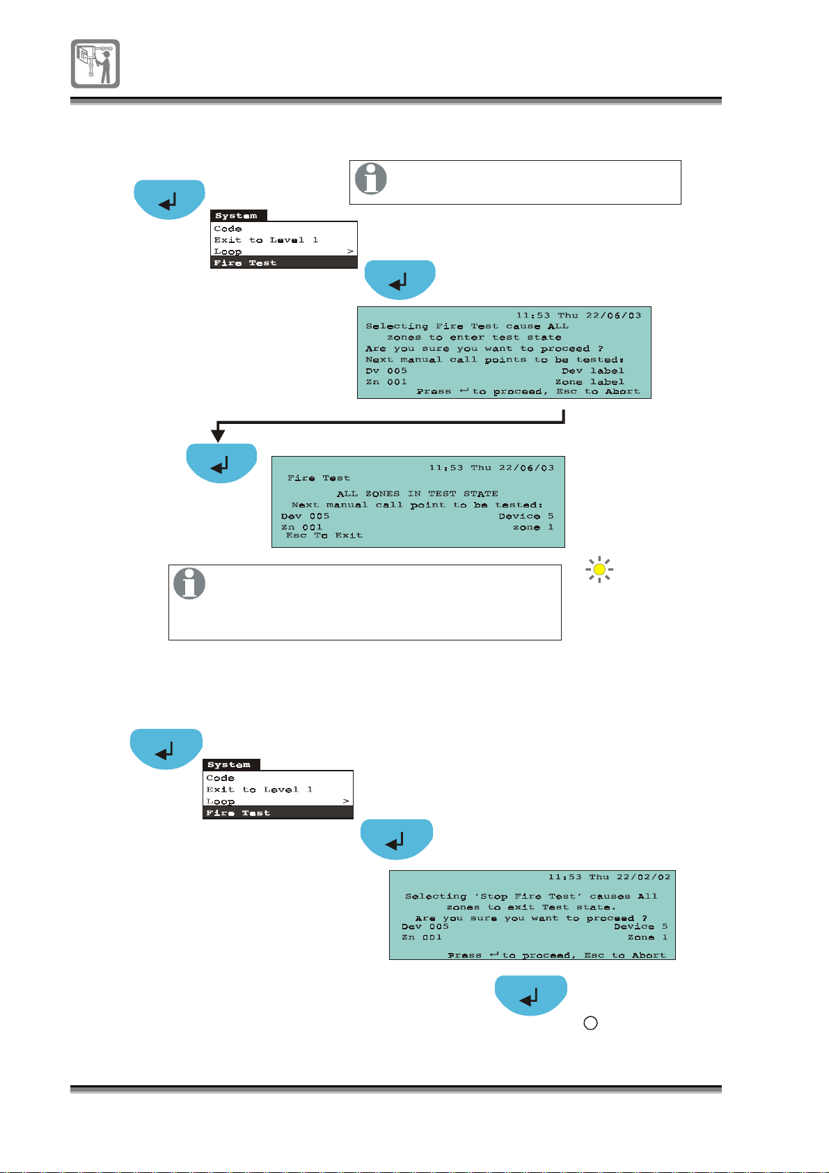
To identify MCP required to be fire tested on a weekly test
g
A2
When in the Fire test mode the panel
will see fire events as test fires.
In Fire test mode the alarms sound for a short
duration and the device is reset thereafter.
The local buzzer may be silenced by pressin
the Cancel buzzer button.
Test
To exit Fire test mode (assuming Fire Test is On)
A2
Test
34
796688 (4188-657)_i2 _06/03
Page 35
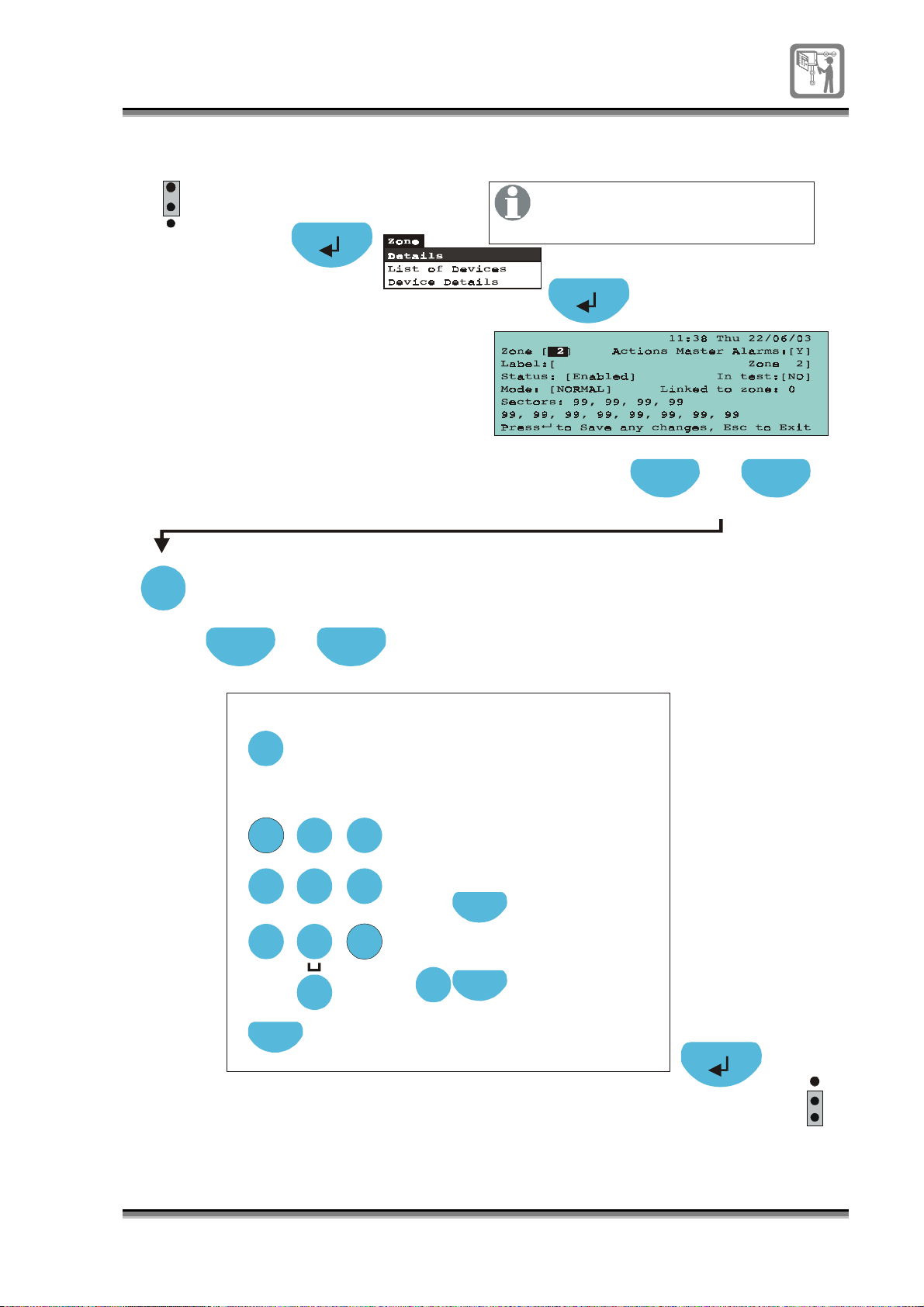
To edit a zone label
g
g
g
y
g
y
g
y
g
y
y
P1
1
2
3
EEPROM
enable
A2
min
If a is left blank
zone label
then the is displayed
device label
in the event of a fire.
Previous Next
Press to select [Zone] field
Select
Press select to chan
e to a required
zone number
Previous Next
Press to select [label] field
To edit text in a field:
Edit
Press Edit button to
allow label editin
the numeric keypad
Usin
enter the label.
ABC
1 2 3
GHI
PQRS
JKL
4 5 6
TUV
7
Next
DEF
MNO
WXYZ
8 9
0
If necessary, press
Next to move to the
next character position.
Each press of an alphanumeric
ke
will scroll character
, eg each press of key 2 will
strin
.
scroll characters: A B C 2 a b c.
Each press of ke
character strin
Each press of ke
character strin
Edit
Function
Function
To copy tex t
Highlight a label
field and press
the Function ke
To paste text
Highlight a label
field and press edit and
then the Function ke
1 will scroll
1 ? , . ; & * /
0 will scroll
0 ( ) : @ [ ]
.
.
P1
1
2
3
EEPROM
enable
796688 (4188-657)_i2 _06/03
35
Page 36
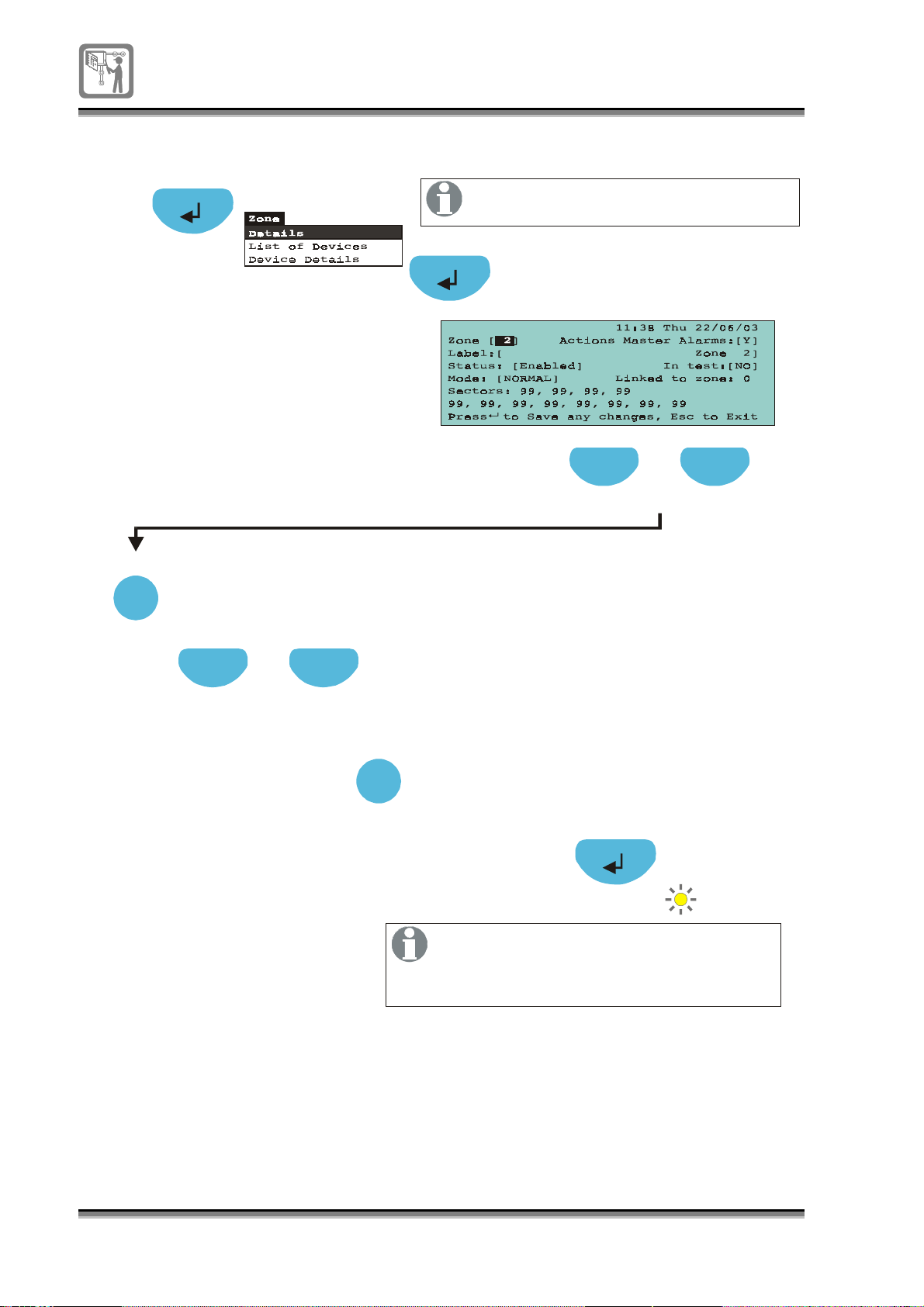
To put a zone in and out of Test mode
g
A2
Select
Press select to chan
zone number
Previous Next
If a zone is put into test mode the panel
will see the zone fire events as test fires.
Previous Next
Press to select a [Zone] field
e to a required
Press to s e lect In Test field [ ]
Select
Press select to toggle
Select NO to take zone out of test
or YES to put the zone in test
When a zone is in the test mode and a
device in the zone is put into fire condition,
the alarms will sound for a short duration
and the device is reset thereafter.
NO/YES
Test
36
796688 (4188-657)_i2 _06/03
Page 37
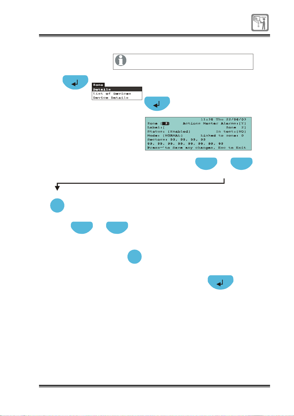
To enable or disable a zone
g
A2
When a zone is disabled the manual call points
in the zone remain active and are NOT disabled.
Previous Next
Press to select [Zone] field
Select
Press select to chan
zone number
Previous Next
Press to select [Status] field
e to a required
Select
Press S e lect to toggle
Select DISABLE to disable the zone
or ENABLE to enable the zone
ENABLE/DISABLE
796688 (4188-657)_i2 _06/03
37
Page 38
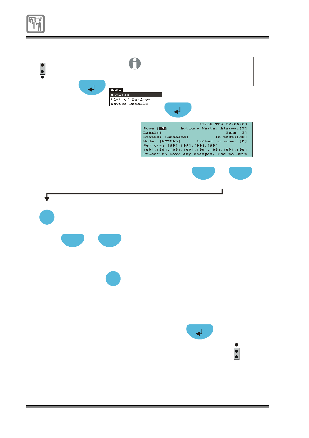
To put a zone in false alarm rejection mode
g
EEPROM
P1
1
2
3
enable
Select
A4
Press Select to chan
zone number
Previous Next
Where a zone is susceptible to false
alarms, a greater immunity to spurious
alarms is possible by putting the zone
in FA rejection mode.
Previous Next
Press to select [Zone] field
e to a required
Press to select [Mode] field
Select
Press S elec t to toggle
2-DETECTOR / 2-ZONES
NORMAL / FA-REJECTION
Select NORMAL for normal operation,
FA-REJECTION for false alarm rejection,
to give greater immunity to spurious alarms,
# 2 DETECTOR for two detector coincidence,
# 2 ZONE for two zone coincidence.
# expained later
P1
1
2
3
EEPROM
enable
38
796688 (4188-657)_i2 _06/03
Page 39
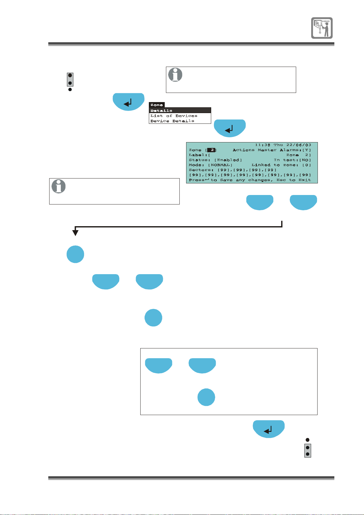
To select 2-detectors or 2-zones coincidence detection
P1
1
2
3
EEPROM
enable
A4
If 2 zones coincidence detection
is selected it is important to link
the selected zone to another zone.
Select
Press Select to change to a required
zone number
Previous Next
The 2-detector coincidence can
only be applied to the selected
zone.
Previous Next
Press to select [Zone] field
Press to select [M ode] field
Select
Procedures
Previous Next
for 2 zone
coincidence only.
Press to select [Linked to zone] field
Press S e lect to toggle to
NORMAL,FA-REJECTION,
2-DETECTOR / 2-ZONES.
Select :2 DETECTOR for two detector coincidence,
2 ZONE for two zone coincidence.
Select
Press Select to change
to a required 2nd zone
number of
two zone coincidence.
1
2
3
EEPROM
enable
P1
796688 (4188-657)_i2 _06/03
39
Page 40
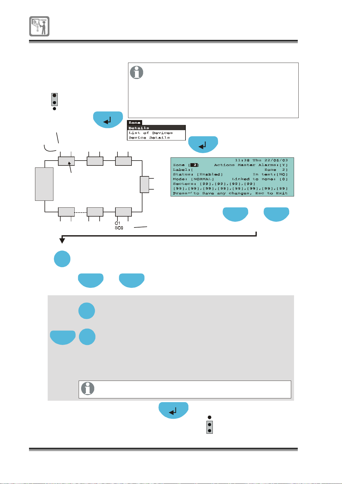
To assign a sectors to zone
g
g
gg
g
P1
1
2
3
EEPROM
enable
A4
There can be a maximum of up to 24 sectors per
system . A sector is an output of a
and each has two outputs.
sounder controller
sounder controller
The sectors are consecutively numbered from
end 1 to end 2 of the loop. A zone can action
up to 12 independent sectors in any
combinations in the system .
Sector 1
Output
End1
Control
panel
End2
S1O1S2
Sounder
controllers
O1
S23O2S24O1S11O2S12
Select
Next
O2S3O1S4O2S5O1S6O2
S
O
7
1
O
S
8
2
O2
Sector 10
S10
Press Select to chan
e to a require zone number
Previous Next
Press to (12 fields available)highlight the first linked field
Sector
Select
Key in or press Select to enter the first number
(ran
e 1 to 24) that is required to be actioned in the event of
the zone going into fire condition.
Select
Highlight by pressing Next the second sector field and key in
the second
linked number that is required to be actioned
in the event of the zone
Sector
oing into fire condition. Repeat the
procedure for other sectors required to be linked to the zone.
Previous Next
Press to select a [Zone] field
link ed
sector
40
796688 (4188-657)_i2 _06/03
Set all rem aining unused fields for no action, enter 00 (zero)
An entry 99 in any field will cause all the to tri
sectors
in the event of fire condition in the zone.
P1
1
2
3
EEPROM
enable
.
er
Page 41
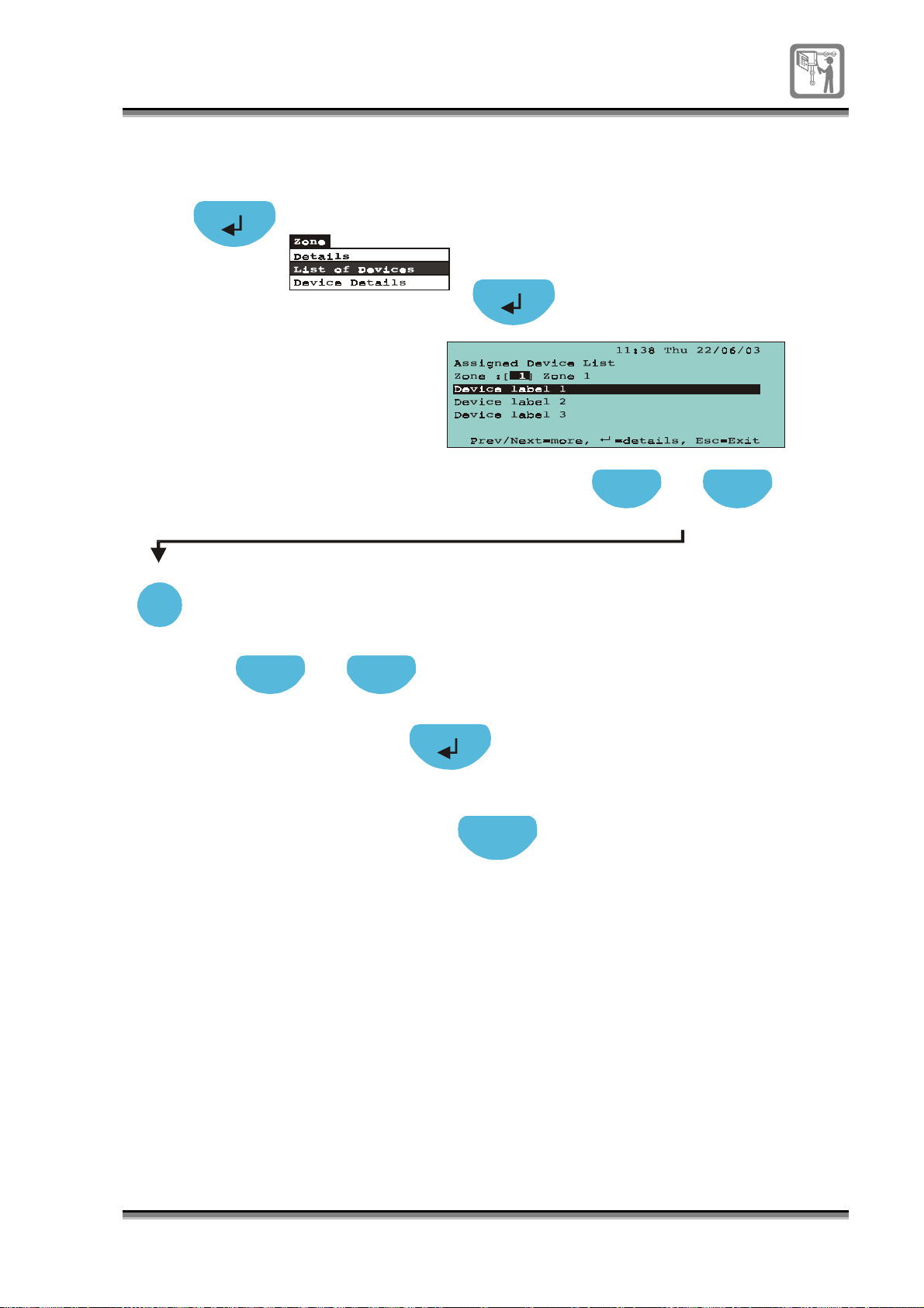
To view devices in a selected zone
A2
Select
Press select to change to a
required zone number
Previous Next
Press to select a [Zone] field
Previous Next
Press to scroll the list
By pressing the Enter button on
a highlighted device it is possible
to view device details,
see device details.
Press to return to Device details
Esc
796688 (4188-657)_i2 _06/03
41
Page 42
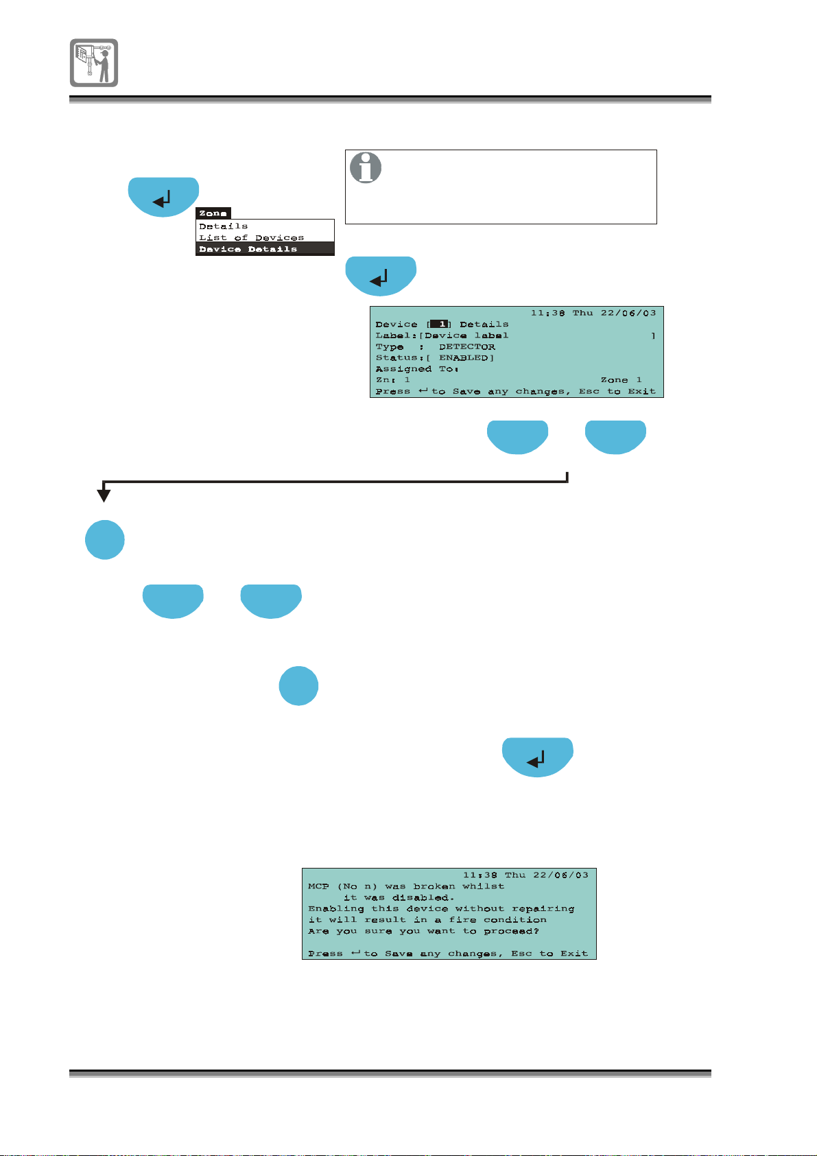
To enable / disable a device
A2
Select
Select
Press select to change to a
required device number
This operation will allow disablement
and enablement of devices like
detectors and manual call points
on the loop.
Previous Next
Press to select [Device] field
Previous Next
Previous Next
Press to select [Status] field
Select
Select
I
f the call point glass
is broken during disablement,
then the following m
appears on enabling the device
essage
Press select to toggle
Select DISABLE to disable the device
or ENABLE to enable the device
ENABLE/DISABLE
42
796688 (4188-657)_i2 _06/03
Page 43
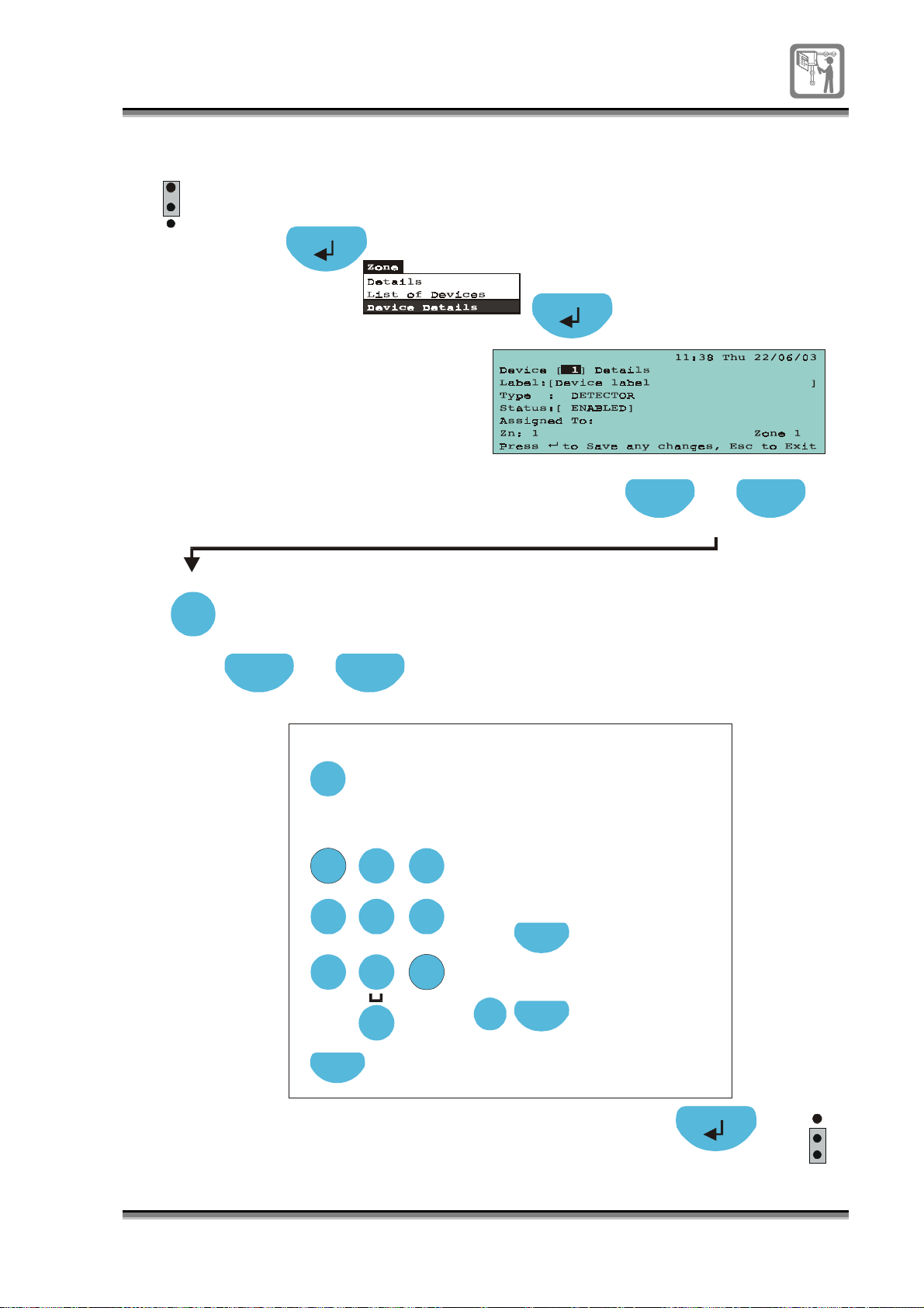
To edit a device label
g
g
y
g
y
g
y
g
y
y
y
P1
1
2
3
EEPROM
enable
A2
Previous Next
Press to select [Device] field
Select
Press to change to a
required device number
Previous Next
Press to select [Label] field
To edit text in a field:
Edit
Press Edit button to
allow label editin
the numeric keypad
Usin
enter the label.
ABC
1 2 3
GHI
PQRS
JKL
4 5 6
TUV
7
Next
If necessary, press
Next to move to the
next character position.
DEF
MNO
WXYZ
8 9
0
Each press of an alphanumeric
ke
will scroll character
, eg each press of key 2 will
strin
.
scroll characters: A B C 2 a b c.
Each press of ke
character strin
Each press of ke
character strin
Edit
Function
Function
To copy text
Highlight a label
field and press
the Function ke
To paste text
Highlight a label
field and press edit ke
followed by the
Function ke
1 will scroll
1 ? , . ; & * /
0 will scroll
0 ( ) : @ [ ]
.
.
EEPROM
P1
1
2
3
enable
796688 (4188-657)_i2 _06/03
43
Page 44
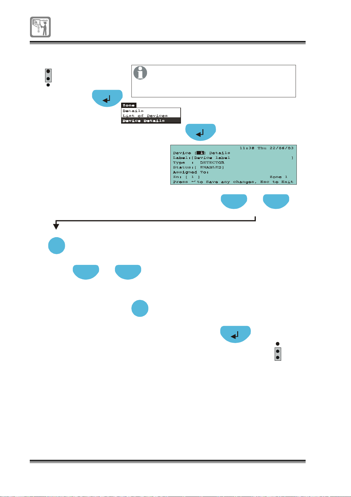
To assign a device to a zone
g
P1
1
2
3
EEPROM
enable
A4
On assigning a Sounder controller device
to a zone the corresponding sectors associated
with the Sounder controller are also assigned
to the zone.
Previous Next
Press to select a [Device] field
Select
Press select to change to a
required device number
Previous Next
Press to [Zn] field
Select
Press select to scroll to
a Zone number
to which the device is assi
ned.
EEPROM
P1
1
2
3
enable
44
796688 (4188-657)_i2 _06/03
Page 45
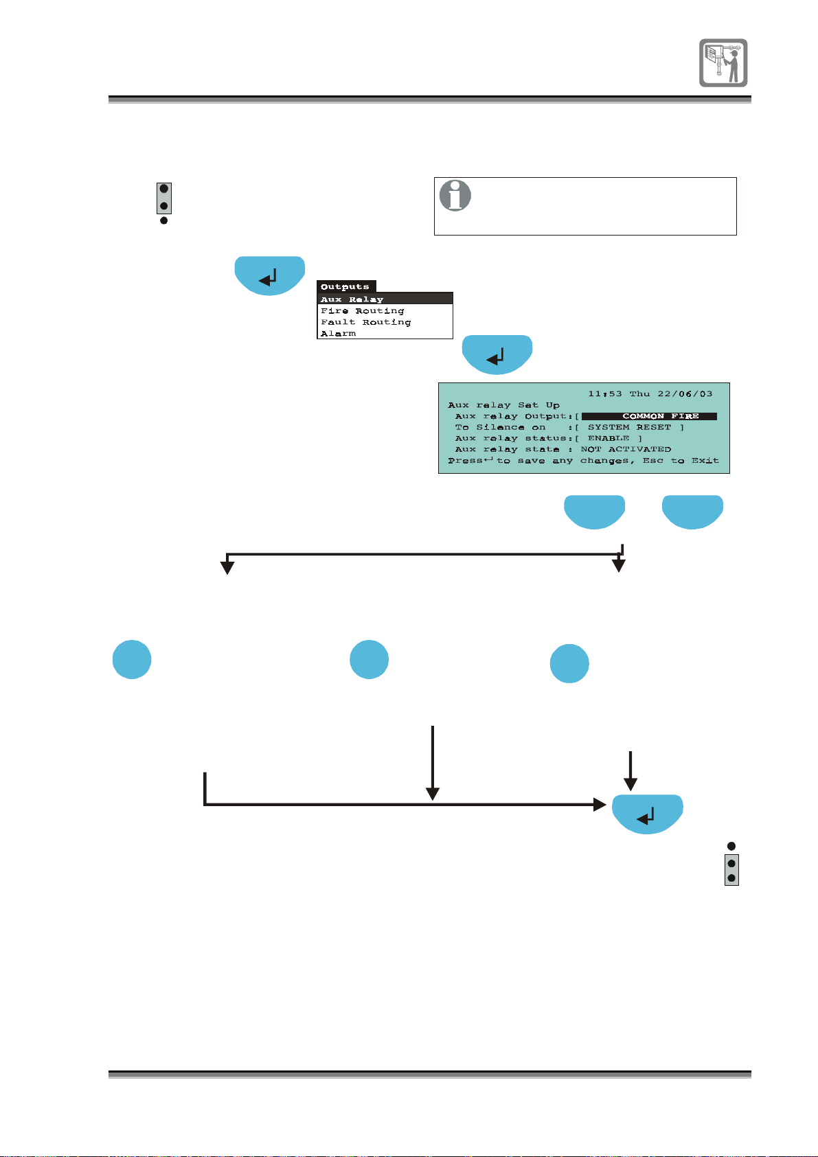
To set auxiliary relay operation
(eg to operate with fire, fault, disablement, pre-alarm or off)
EEPROM
P1
1
2
3
enable
A2
min
Only configure the hardware link
when setting the
of auxiliary relay.
operation
Previous Next
A2
Select
Press to select a field [ ]
Auxiliary relay output: To silence on:
Press select to scroll to
the required selection:
NOT CONNECTED
COMMON FIRE
(Default)
COMMON FAULT
COMMON DISABLEMENT
PRE ALARM
A2
Select
Auxiliary relay
Status:
Press select
to scroll to
state:
ENABLE
DISABLE
A3
Select
Select
Press select to toggle
selection between:
SYSTEM RESET
(Default)
SILENCE ALARMS
EEPROM
P1
1
2
3
enable
796688 (4188-657)_i2 _06/03
45
Page 46
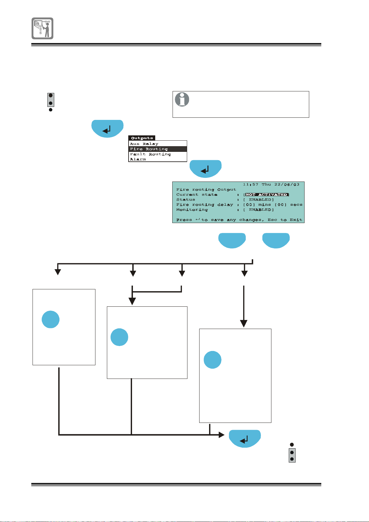
To set fire routing output operation
y
g
(eg change activation type, delayed operation of relay and
monitoring)
P1
Only configure the hardware link
when setting and
of the fire routing output.
dela
Previous Next
Previous Next
Previous Next
EEPROM
1
2
3
enable
A2
min
monitorin
[Curre nt state ] [Status] [Fire routing delay][M onitoring]
A2
Select
A3
Select
Press to toggle
selectionbetween:
NOT ACTIVATED
ACTIVATED
Press to toggle
selection between:
ENABLED
DISABLED (Default)
Press to select field [ ]
Press to select field [ ]
Press to select field [ ]
A4
Select
Press to increment
0 to 9 minutes.
(0 - default)
Press to increment
from 0 to 59 seconds
(00 - default).
46
796688 (4188-657)_i2 _06/03
EEPROM
P1
1
2
3
enable
Page 47
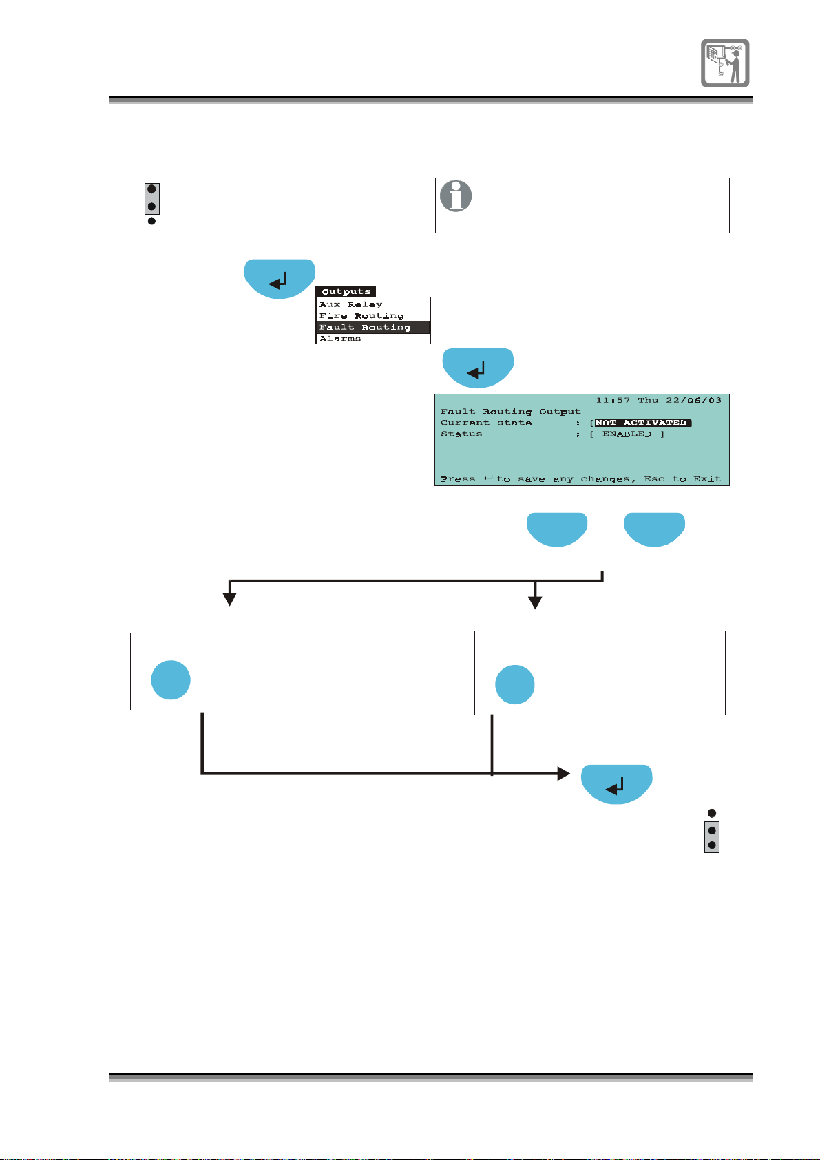
To set fault routing operation
(eg activation type)
P1
1
2
3
EEPROM
enable
Only configure the hardware link
when setting of the
status
fault routing output.
A2
A2
Select
min
Previous Next
Previous Next
Previous Next
Press to select field [ ]
Press to select field [ ]
Press to select field [ ]
[C urre nt state] [Status]
Press to toggle selection
between:
NOT ACTIVATED
ACTIVATED
A3
Select
Press to toggle selection
between:
ENABLED
DISABLED (Default)
1
2
3
EEPROM
enable
796688 (4188-657)_i2 _06/03
P1
47
Page 48
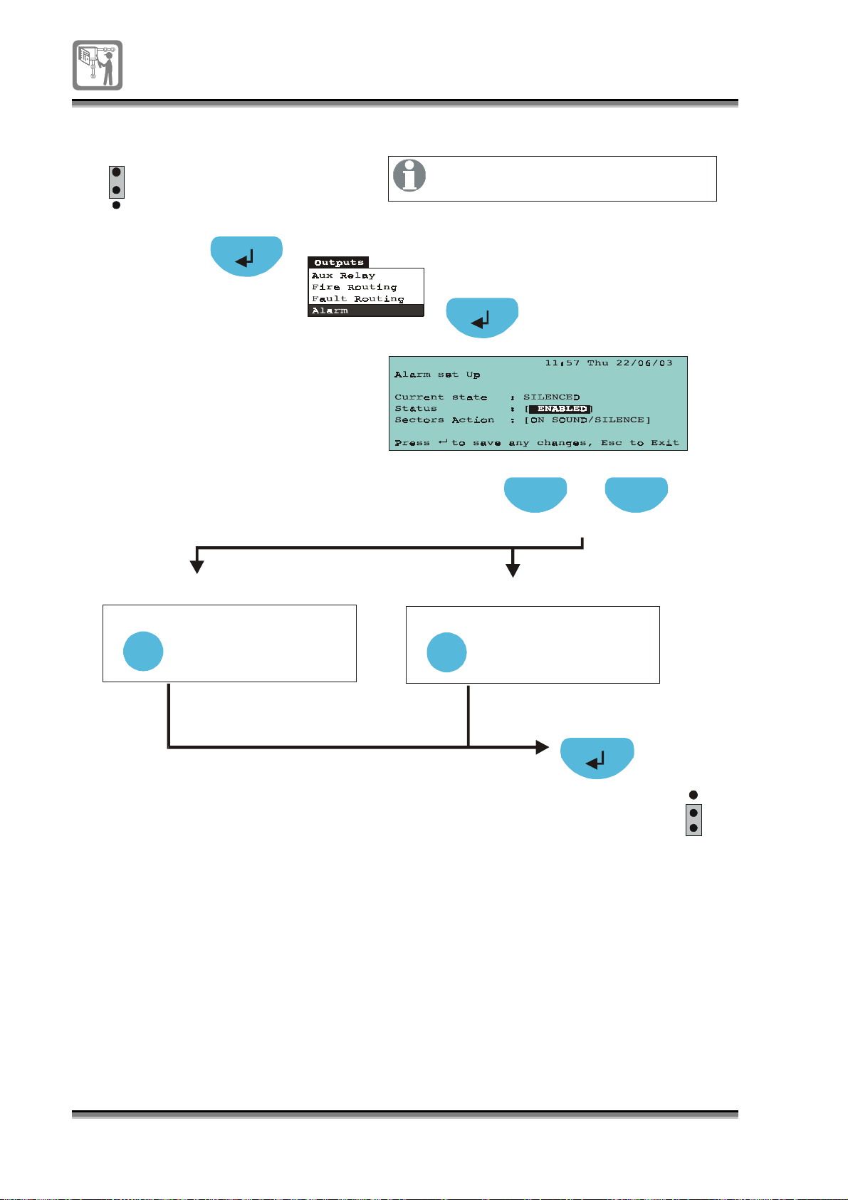
To view / enable or disable alarms sounders
g
EEPROM
P1
1
2
3
enable
Only configure the hardware link
when settin
of Alarms.
sector action
A2
A2 A4
Select
min
[Status] [Sectors Action]
Press to toggle selection
between:
ENABLED (Default)
DISABLED
Select
Previous Next
Previous Next
Previous Next
Press to select field [ ]
Press to select field [ ]
Press to select field [ ]
Press to toggle selection
between:
ON SOUND/SILENCE
ON FIRE/RESET
48
796688 (4188-657)_i2 _06/03
EEPROM
P1
1
2
3
enable
Page 49
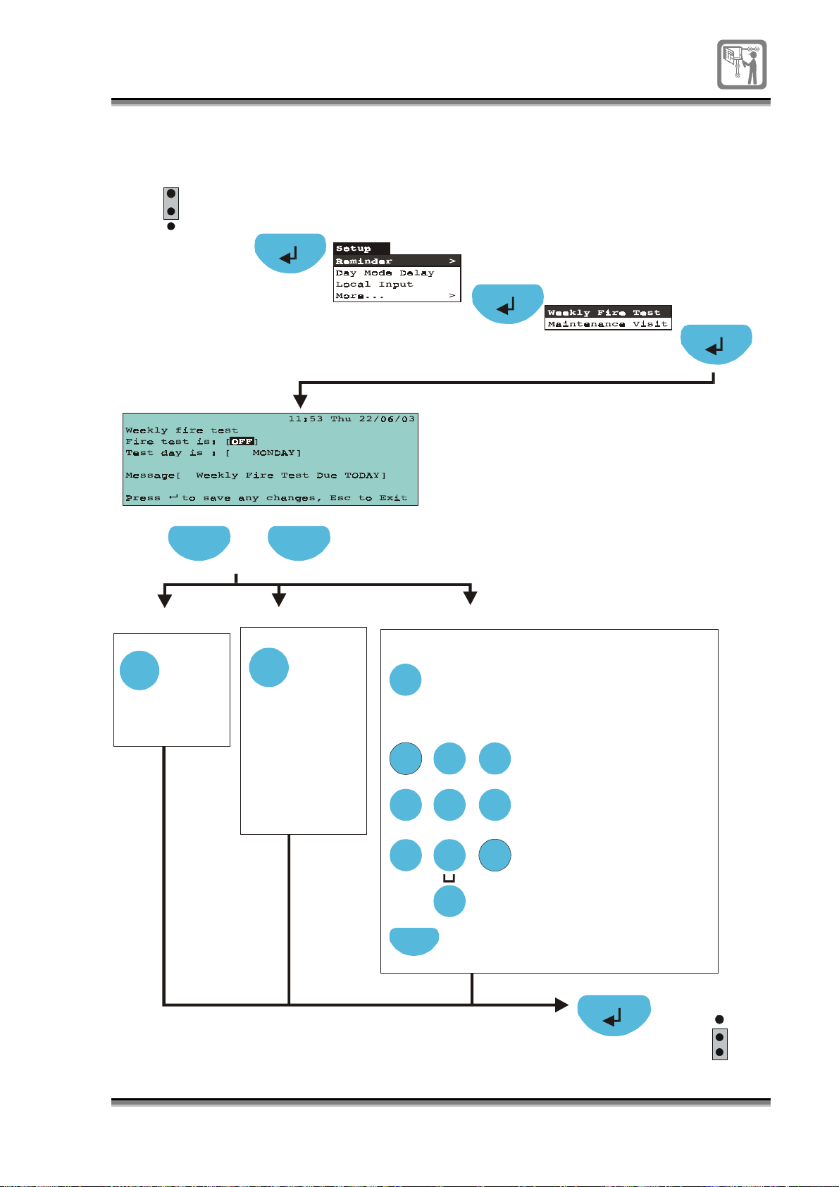
To set weekly alarm test reminder message
g
g
y
g
g
y
y
g
y
g
( )
(eg day and message)
P1
1
2
3
EEPROM
enable
A2
Previous NextPrevious Next
Press to select field [ ]
[Fire test is] [Test day is]
Select
Press to toggle
Press to toggle
ON/OFF
ON/OFF
(OFF -Default)
(OFF -Default)
Select
Press to toggle:
MONDAY
TUESDAY
WEDNESDAY
THURSDAY
FRIDAY
SATURDAY
SUNDAY
[M essage]
To edit text in a field:
Edit
Press Edit button to
allow label editin
the numeric keypad
Usin
enter the label.
ABC
1 2 3
GHI JKL
4
PQRS
TUV
7 8 9
Next
If necessary, press
Next to move to the
next character position.
DEF
MNO
5 6
WXYZ
0
Each press of an
alphanumeric
ke
.
will scroll
character strin
each press of
e
2 will scroll
ke
characters: A B C 2 a b c.
Each press of
1 will scroll
ke
character strin
1 ? , . ; & * /
Each press of ke
0 w ill scroll
character strin
: @ [ ]
0
,
P1
1
2
3
EEPROM
enable
796688 (4188-657)_i2 _06/03
49
Page 50
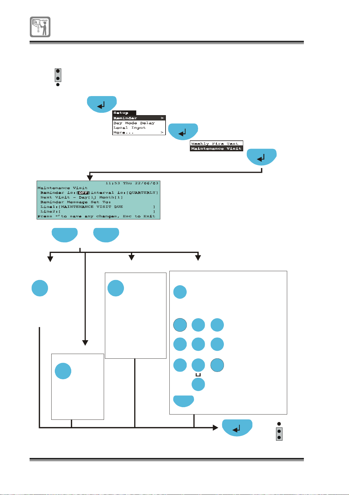
To set / view maintenance reminder message
gg
g
g
y
g
g
y
y
g
y
g
( )
y
g
gg
P1
1
2
3
EEPROM
enable
A2
Previous NextPrevious Next
min
Press to select field [ ]
[Reminder is]
Select
Press select
to to
le
ON/OFF
(OFF -Default)
A4
[Test Interva l is]
Select
Press to toggle:
MONTHLY
QUARTERLY
BI-ANNUALLY
ANNUALLY
A2
Select
[D ay]
Press select to
increment da
1 to 31
Press next
hlight [m onth]
to hi
and press select
to to
le m onths
A2
[M essage]
To edit text in a field:
Edit
Press Edit button to
allow label editin
the numeric keypad
Usin
enter the label.
ABC
1 2
GHI
PQRS
JKL
4 5 6
TUV
7 8 9
0
Next
If necessary, press
Next to move to the
next character position.
DEF
3
MNO
WXYZ
Each press of an
alphanumeric
ke
.
will scroll
character strin
each press of
e
2 will scroll
ke
characters:
A B C 2 a b c.
Each press of
1 will scroll
ke
character strin
1 ? , . ; & * /
Each press of ke
0 will scroll
character strin
: @ [ ]
0
EEPROM
,
P1
1
2
3
enable
50
796688 (4188-657)_i2 _06/03
Page 51
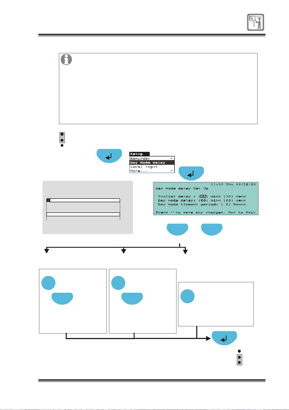
To set Delay and Verify functions
y
g
g
y
g
y
y
y
y
The in the system can be delayed on a fire condition.
alarm sounders
The can be confi
Initial dela
(factory set to 30 seconds). This delay is imposed on the
alarm sounders at the be
facility is active with the delay LE D lit.
The is an extended alarm delay to verify a fire alarm.
Day mode delay
This delay value can be up to 9 minutes 59 seconds. Note this value is
the total delay duration from the start of a fire condition. It is made active
on pressin
LED is lit. The is the duration over which
Delay and Verify functions can be operated.
P1
1
2
3
EEPROM
enable
A2
Alarm delay operation
Initial de la
30s factory default
min
the Verify button when initial Delay is active and delay
Day mode timeout period
inning of a fire condition, providing the Delay
ured up to 9 minutes 59 seconds
mode dela
Da
Start of
alarm
[Initial delay]
A2
(initial Verify delay)
Select
Press to increment
0 to 9 minutes.
Next
Press to select
seconds field [ ]
Press to increment
from 0 to 59 seconds.
Maximum alarm dela
9min 59sec
[D ay mode delay]
A2
(extended Verify delay)
Select
Press to select
seconds field [ ]
Press to increment
from 0 to 59 seconds.
Previous Next
Press to select field [ ]
Press to increment
0 to 9 minutes.
Next
A3
[D ay mode timeout period]
(Verification Delay mode timeout)
Select
Press to increment
from 1 to 8 hours.
If 0 hours is entered
then the Dela
mode
is disabled
P1
1
2
3
EEPROM
enable
796688 (4188-657)_i2 _06/03
51
Page 52
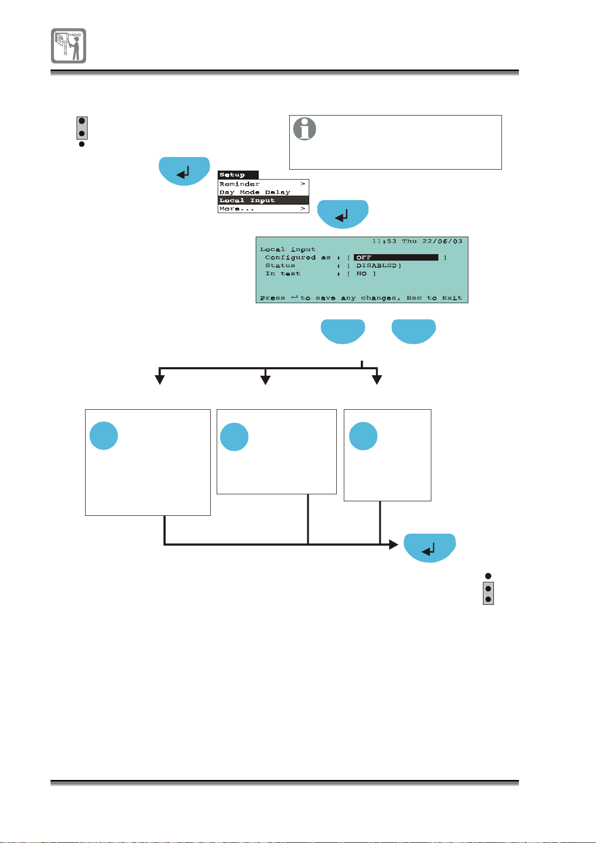
To set the Local input
P1
1
2
3
EEPROM
enable
A2
It is only necessary to configure
hardware link P1 when changing
the settings in the
field.
Previous Next
Press to select field [ ]
Configured as
A4
Press to toggle:
LOCAL FIRE INPUT
OFF
CLASS CHANGE
EXTERNAL EVACUATE
[Configured as]
Select
A3
Select
Press to toggle:
ENABLE
DISABLE (Default)
[Status]
A2
[In test]
Select
Press to toggle:
YES
NO (Default)
EEPROM
P1
1
2
3
enable
52
796688 (4188-657)_i2 _06/03
Page 53
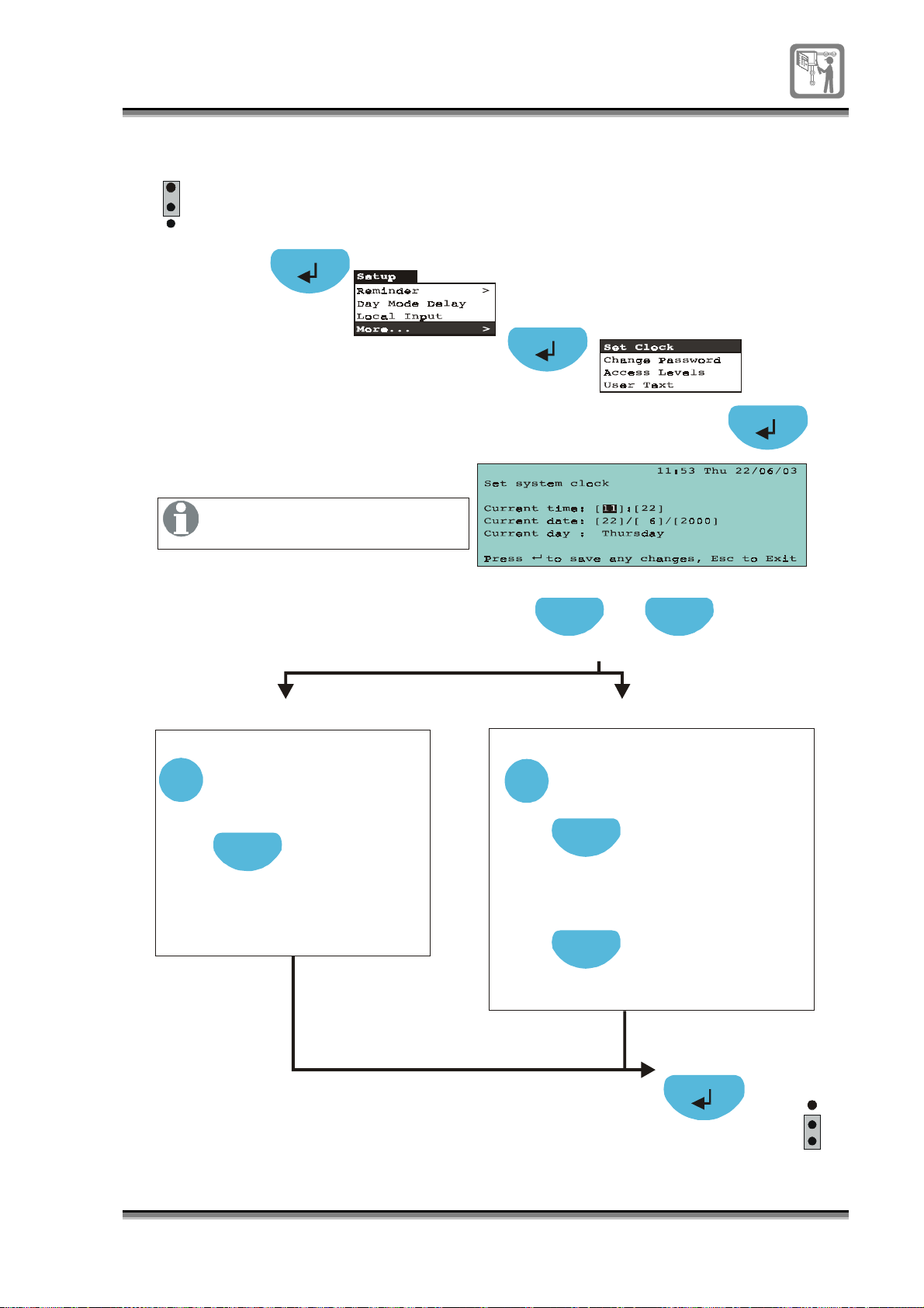
To set time and date
g
g
P1
1
2
3
EEPROM
enable
A3
All numeric fields can be set by
pressing the numeric keys.
Previous Next
Select
[Curre nt tim e]
Press se lect to toggle:
Hours 00 to 23
Next
Press next to highlight the
[minutes] field
Press se lect to toggle:
Minutes 00 to 59
Press to select field [ ]
[Current day]
Select
Press select to toggle:
Date:
Day 1-31
Next
Press next to hi
the [m onth ] field
Press se lect to toggle:
Date:
Month 1-12
Next
Next
Press next to hi
the [year] field
Press to toggle:
Date:
Year 2000-2099
hlight
hlight
EEPROM
enable
P1
1
2
3
796688 (4188-657)_i2 _06/03
53
Page 54
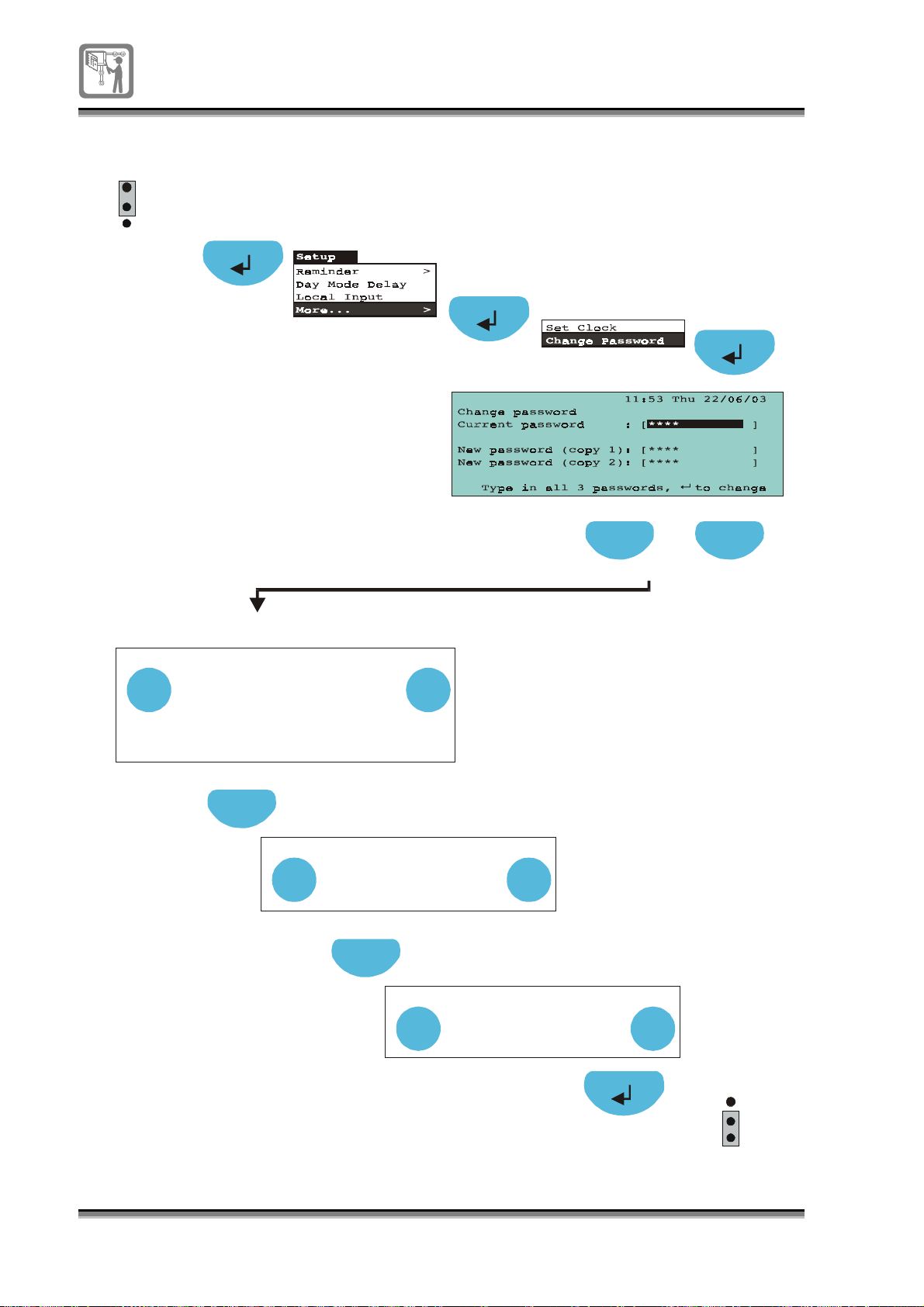
To change an existing password
P1
1
2
3
EEPROM
enable
A3
Previous Next
Press to select field [ ]
[Current password]
Edit
Enter the current password
using the numeric keypad:
Access level 2 - 2222
Access level 3 - 3333
Access level 4 - 4444
Next
Press next to highlight
New password (copy 1) field [ ]
Edit
Edit
Enter New password
(must be minimum
4 numeric characters)
Next
Press next to highlight
New password (copy 2) field [ ]
Edit
Enter New password
again to the confirm
copy 1 entry
Edit
Edit
54
796688 (4188-657)_i2 _06/03
EEPROM
P1
1
2
3
enable
Page 55
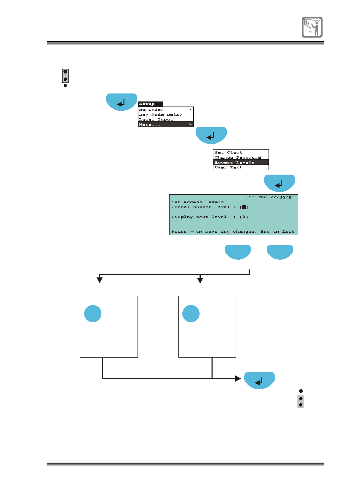
To set up the access level for Cancel buzzer and Display test controls
P1
1
2
3
EEPROM
enable
A4
[Cancel buzzer level]
Select
Press to toggle:
Between
Access level
1 and 2
Previous Next
Press to select field [ ]
[Display test level]
Select
Press to toggle:
Between
Access level
1 and 2
EEPROM
P1
1
2
3
enable
796688 (4188-657)_i2 _06/03
55
Page 56
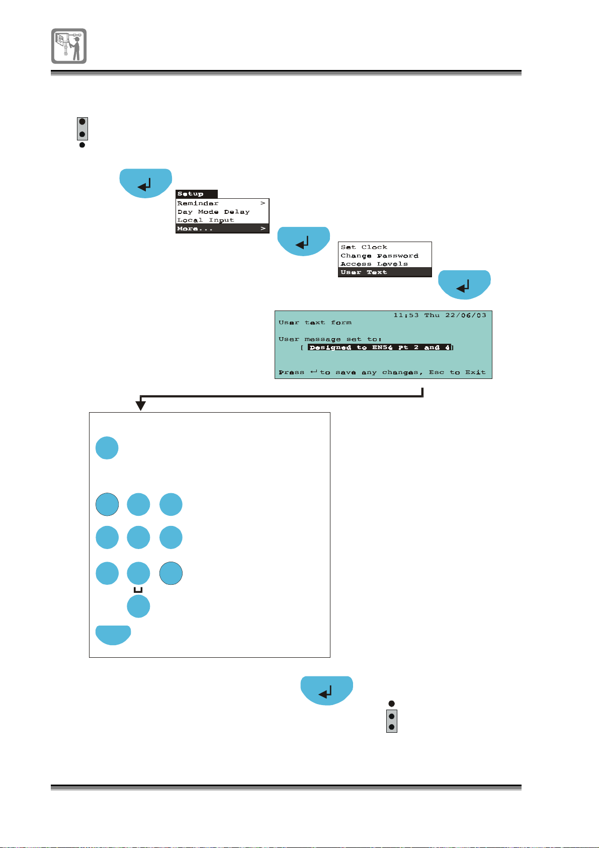
To edit User text
g
g
y
g
g
y
y
g
y
g
P1
1
2
3
EEPROM
enable
A4
To edit text in a field:
Edit
Press Edit button to
allow label editin
Usin
the numeric keypad
enter the label.
ABC
1 2 3
GHI
PQRS
JKL
4 5 6
TUV
7
Next
If necessary, press
Next to move to the
next character position.
DEF
MNO
WXYZ
8 9
0
Each press of an
alphanumeric
ke
.
will scroll
character strin
each press of
e
2 will scroll
ke
characters: A B C 2 a b c.
Each press of
1 will scroll
ke
character strin
1 ? , . ; & * /
Each press of ke
0 will scroll
character strin
0 ( ) : @ [ ]
,
P1
1
2
3
EEPROM
enable
56
796688 (4188-657)_i2 _06/03
Page 57
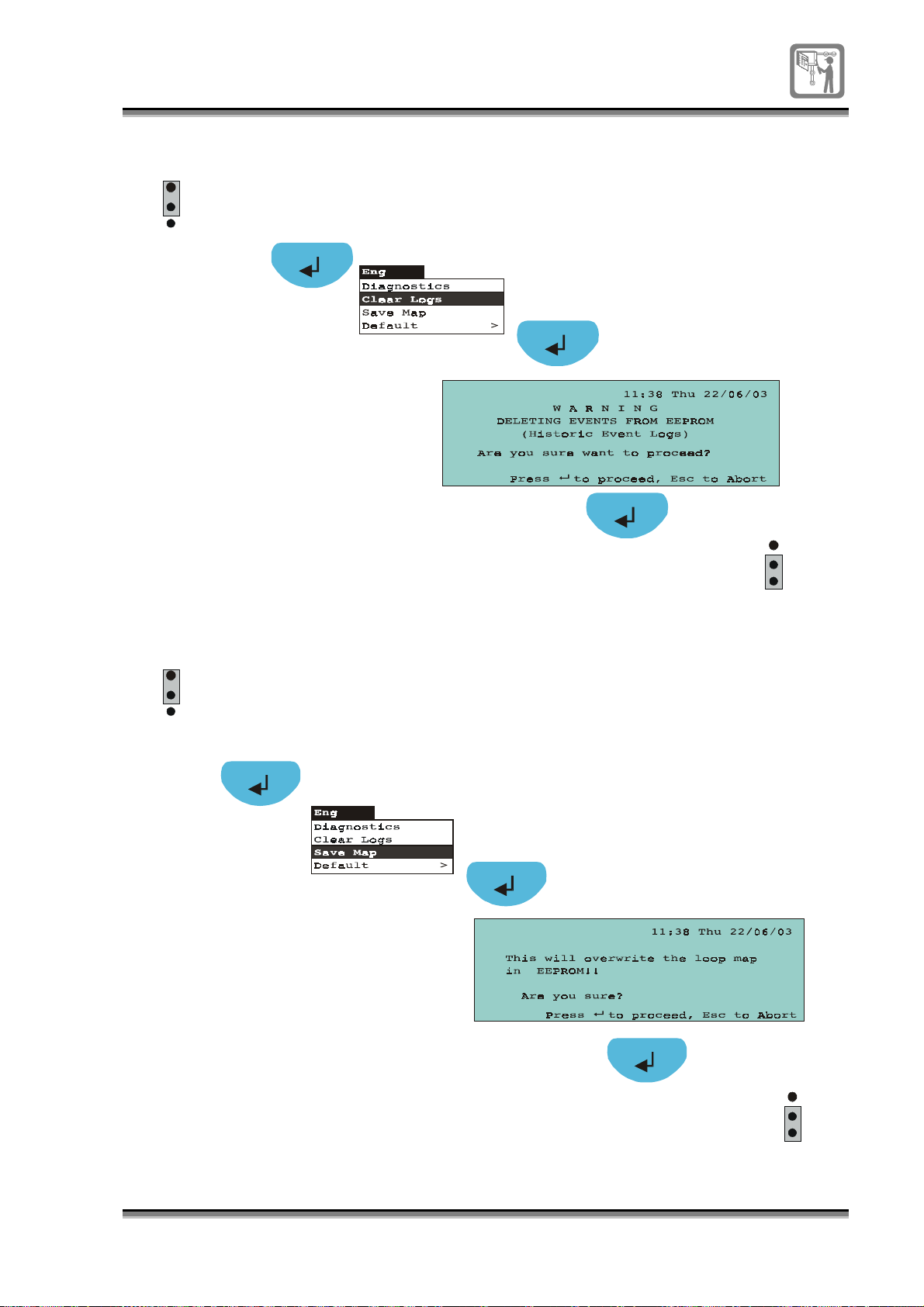
To clear logs
P1
1
2
3
EEPROM
enable
A4
Historic event log is erased
EEPROM
P1
1
2
3
enable
To save the loop map
P1
1
2
3
EEPROM
enable
A4
Loop map is saved
EEPROM
P1
1
2
3
enable
796688 (4188-657)_i2 _06/03
57
Page 58
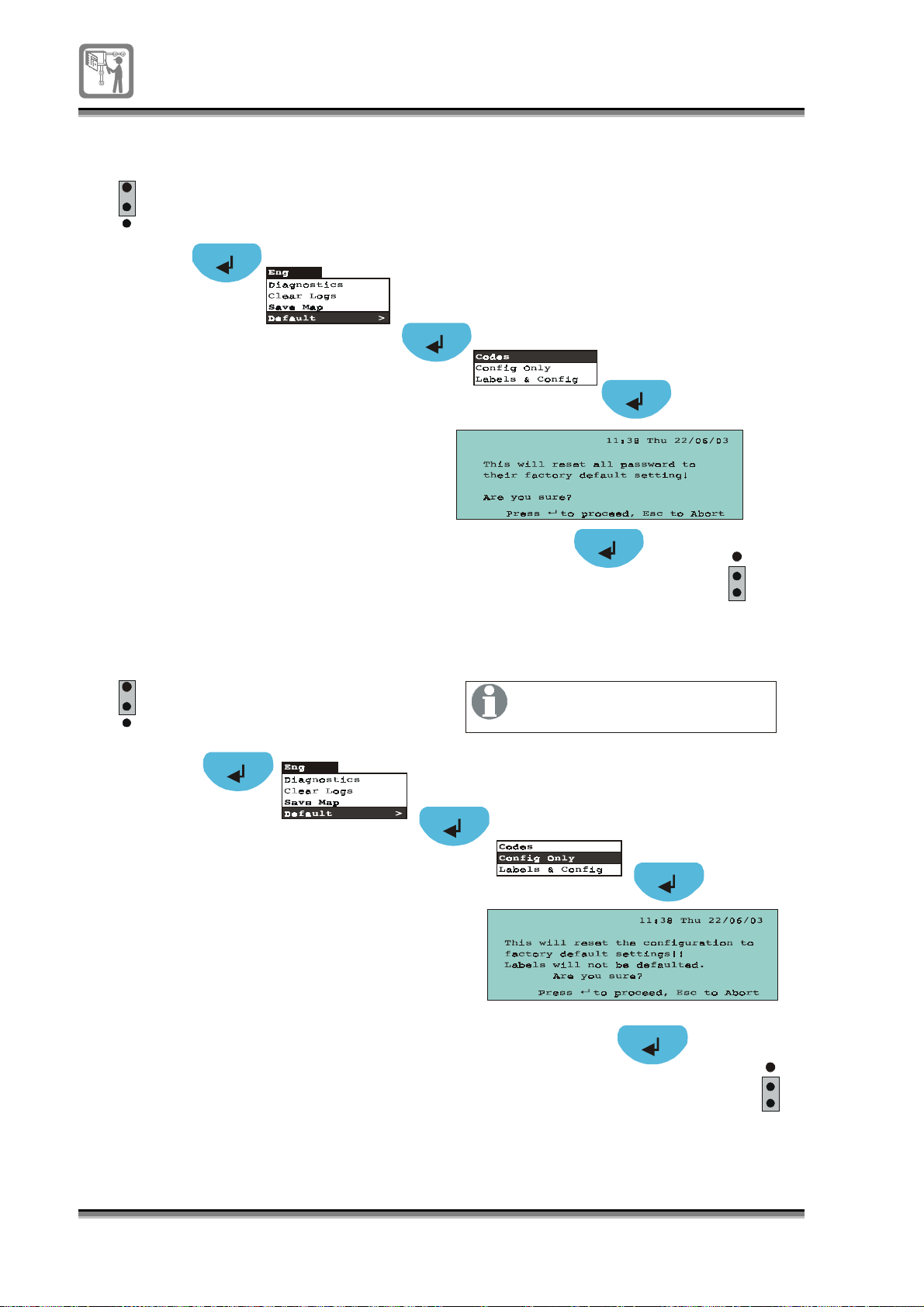
To reset all access codes to factory settings
g
P1
1
2
3
EEPROM
enable
A4
Codes are reset
EEPROM
P1
1
2
3
enable
To reset the panel configuration to factory settings
P1
EEPROM
1
2
3
enable
Device and Zone labels are not
affected by this operation.
A4
Configuration is reset
to factory default settin
P1
1
EEPROM
2
3
enable
s
58
796688 (4188-657)_i2 _06/03
Page 59
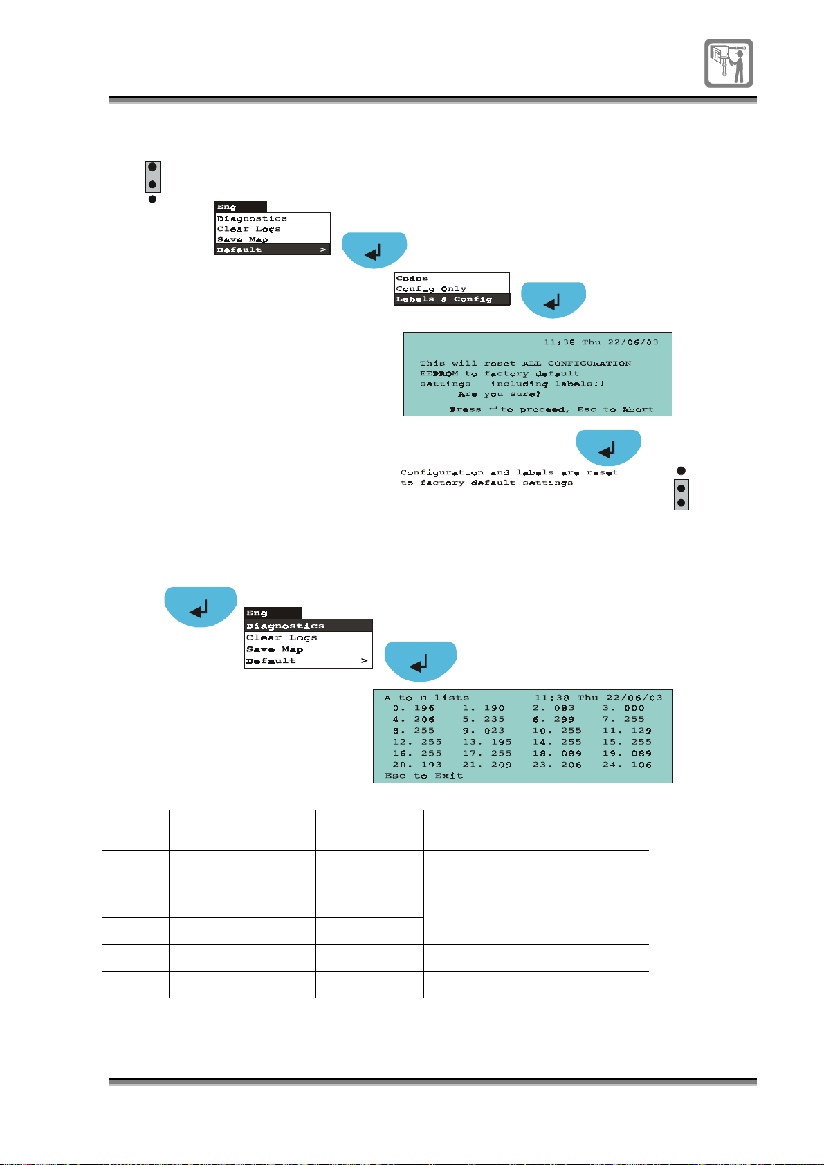
To reset all configurations and labels to factory settings
P1
1
2
3
EEPROM
enable
A4
EEPROM
P1
1
2
3
enable
To view diagnostic data
A3
A to D
reference
A fault is indicated if the A to D value is outside the limits.
Description of A to D
reading
0 Mains 140 - Mains fault - Below the lower limit.
1 Earth 74 204 Earth fault – Outside the two limits
2 5V 223 255 5V supply fault – Outside the two limits
3 12V 1 255 12V supply fault – Outside the two limits
4 24V 140 203 24V supply fault – Outside the two limits
5 Sounder 1 58 150
6 Sounder 2 58 150
7 Battery charger
8 Initial battery 1 voltage
9 Initial battery 1 current
10 Final battery 1 voltage
11 EEPROM Charger (PWM)
Lower
limit
Higher
limit
Condition
Short circuit fault if belwo the lower limit
Open circuit fault if above the higher limit
796688 (4188-657)_i2 _06/03
59
Page 60
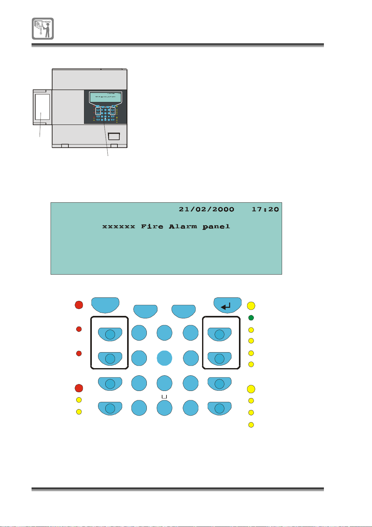
Appendix – Description of Controls and indicators
A
Previous Next
1
GHI JKL MNO
4 5 6
PQRS TUV
7 8 9
Select
Fault
Power
ABC
DEF
Reset
System Fault
2 3
Power Fault
Can c el Bu zz er
FRE Fault
A – Flap
Sounder Fault
WXYZ
Di spl ay Te st
Disablement
Edit
Function
FRE Disablement
0
Sounder Disablement
Test
B – Instructions
C – Controls and indicators
C
B
Fire Routing
Fire Protection
Verification
Fire
Esc
Sound Alarms
Activated
Silence Alarms
Activated
Delay
Pre-alarm
Verify
Delay
Fire
Fire Routing
Activated
Fire Protection
Activated
Pre-Alarm
Delay
Verification
Esc
Sound Alarms
Silence Alarms
Delay
Verify
Previous Next
ABC
1 2
GHI JKL
DEF
3
MNO
4 56
PQRS
TUV
WXYZ
7 8 9
Select
Edit
0
Reset
Cancel Buzzer
Di spl ay Te st
Function
Fault
Pow er
System Fault
Pow er Fau lt
FRE Fault
Sounder Fault
Disablement
FRE Disablement
Sounder Disablement
Test
60
796688 (4188-657)_i2 _06/03
Page 61
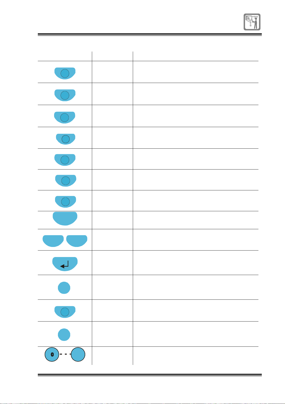
Controls
s
Control Access level Function
Verify
Delay
Sound Alarms
Silence Alarm
Reset
Cancel Buzzer
Display Test
2 The button further delays the alarm from sounding
for a pre-configured time (up to 10 minutes) only if
Delay mode is active.
2 The button activates the delay mode for a pre-
configured time of up to 8 hours.
2 The button starts the alarm sounders in the
system.
2 The button stops the alarm sounders from
sounding in the system.
2 The button resets the panel.
1(default)/ 2 The button silences the audible warning buzzer at
the panel.
1 /
2(default)
The button tests the LED indicators, buzzer and
display at the panel.
Esc
Previous Next
Select
Function
Edit
9
1 The button functions as a quit or escape key.
1 These buttons are used to scroll through active
event list, form fields and menu options.
1 This button is used to enter or accept a menu
option.
2 The button toggles the selections of a field in a
form.
2 The button is used in the edit mode to copy and
paste text in a label field.
2 The button allows editing of text entry in a field of a
form.
1 These buttons are used for entering numeric data.
796688 (4188-657)_i2 _06/03
61
Page 62
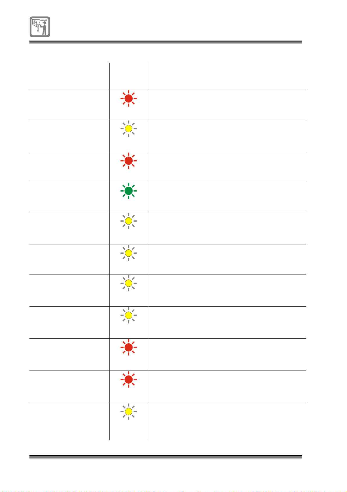
Light indications
Indication
Light
colour Status of light and meaning
Fire
Fault
Pre Alarm
Power
System fault
Power fault
(Red)
(Yellow)
(Red)
(Green)
(Yellow)
(Yellow)
STEADY
system.
OFF
STEADY
view the fault log for details.
OFF
STEADY
device in the pre alarm state.
OFF
STEADY
OFF
supply.
STEADY
non-volatile memory corruption).
OFF
STEADY
fault.
OFF
– There is one or more fire(s) in the
– There are no fire(s) in the system.
– There is at least one fault in the system,
– There are no faults.
– There is at least one coincidence zone /
– There are no zones/device in coincidence fire.
– The mains & battery are healthy
– The panel has no mains supply or battery
– There is a system fault (MCU failure and
– There is no system fault.
– There is either a mains or battery supply
– There is no power fault.
FRE Disablement
FRE fault
Fire Protection Activated
Fire Routing Activated
Sounder fault
(Yellow)
(Yellow)
(Red)
(Red)
(Yellow)
STEADY
disabled.
OFF
STEADY
equipment.
OFF
STEADY
activated and there is an automatic fire call out.
OFF
STEADY
OFF
STEADY
circuit fault.
OFF
– The fire routing equipment (FRE) is
– The FRE is not disabled.
– There is a fault with fire routing
–There is no fault with fire routing equipment.
– The fire protection output has been
– The fire protection output is not active.
– The fire routing output is active.
–The fire routing is not active.
– There is a sounder circuit open or short
– There is no sounder circuit fault.
62
796688 (4188-657)_i2 _06/03
Page 63
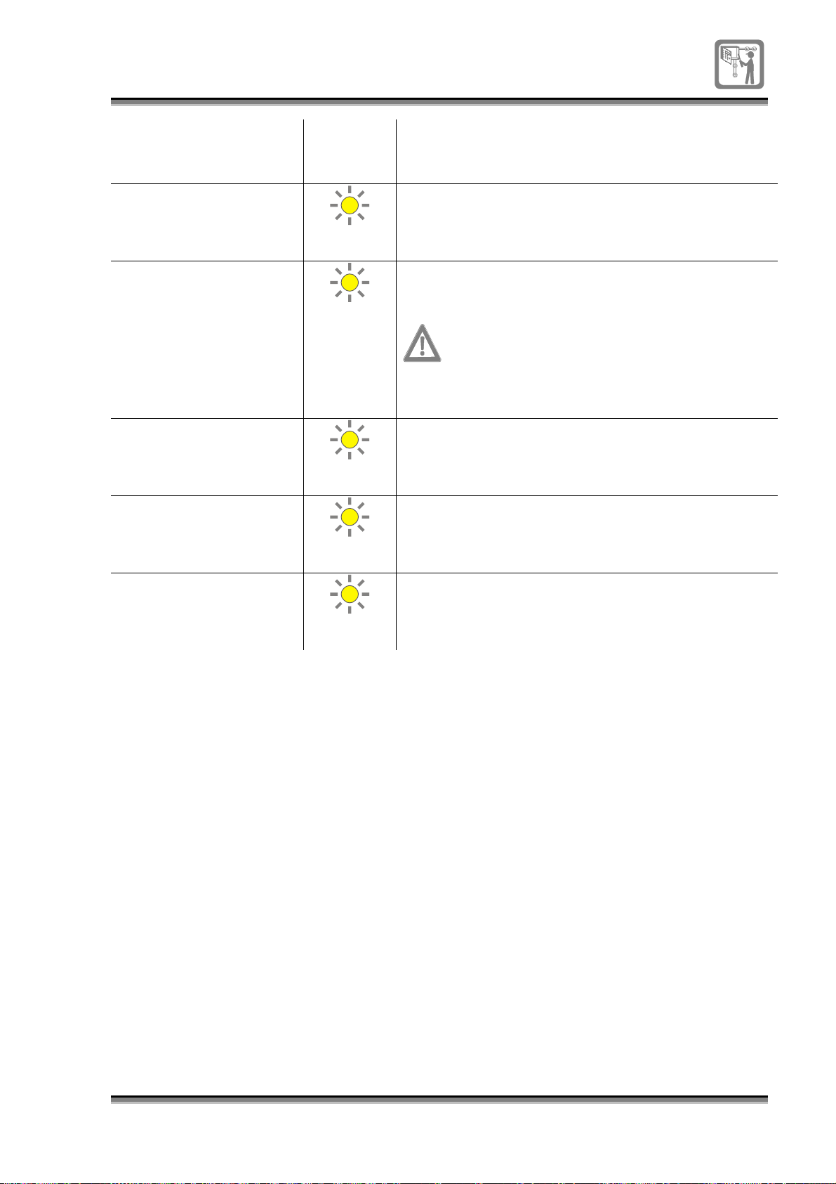
Indication
Light
colour Status of light and meaning
Sounder Disablement
Disablement
Delay
Verification
Test
(Yellow)
(Yellow)
(Yellow)
(Yellow)
STEADY
OFF
STEADY
panel is in engineering mode, view the disablement
log for details.
the servicing organisation.
OFF – There are no disablement.
STEADY
OFF
STEADY
are being delayed from sounding.
OFF
STEADY
– The system alarm sounders are disabled.
– The system alarm sounders are not disabled.
– There is at least one disablement or the
The engineering mode is normally accessed by
– The delay mode is active.
– The delay mode is not active.
– The verification delay is active and alarms
– The verification delay is not active.
– The panel is in test state.
(Yellow)
– The panel is not in test state.
OFF
796688 (4188-657)_i2 _06/03
63
Page 64

Message description list for System 800
Any service and maintenance work on the panel or system must be carried out by a
trained maintenance engineer from the fire alarm servicing organisation.
Message displayed Description and checks
12V supply failed
12V supply OK
24V supply failed
24V supply OK
5V supply failed
5V supply OK
Access codes
reset
Access denied!
Access level
changed
Alarms silenced
Alarms sounded
Allocation Tx
Error
All zones in test
All zones out of
test
Batteries
discharged
Batteries
disconnected
Battery fault
cleared
Cannot put all
zones into test
Cannot test fire
input
Charger fault
Charger fault
Cleared
Class change Off
Class change
operated
Clock settings
saved
Customer mode
entered
The panel 12V supply has failed.
The panel 12V supply is OK.
The panel 24V supply has failed.
The panel 24V supply is OK
The panel 5V supply has failed.
The panel 5V supply is OK
The access codes have been manually reset to the factory
default settings.
The command or menu option selected cannot be executed at
the current access level. Enter a higher access level.
The access level has changed.
The fire alarms in the system have been manually silenced.
The fire alarms in the system have been manually activated
and are sounding.
The panel is not getting a response when communicating with
a device on the loop circuit.
All zones of the system have been manually put into a weekly
fire test state.
All zones of the system have been taken OUT of weekly fire
test.
The panel 12V 7Ahr batteries are discharged.
Replace batteries in the panel.
The panel 12V 7Ahr batteries have been disconnected.
The battery disconnection or discharge fault has cleared.
The panel is in a fire condition and a manual attempt to put all
zones into weekly fire test state is rejected.
Ensure the panel is not in fire condition before putting all zones
into test state.
The panel is in fire condition, therefore manual attempt to test
the fire input is rejected.
The battery charger in the panel has developed a fault.
Check the battery circuit wiring and battery fuse.
The fault associated with the battery charger circuit on the
electronic module has been cleared.
The class change input has been switched off.
The class change input has been operated and the sounders
in the system are active.
Changes made to the clock settings have been saved.
The customer mode has been entered to allow access to
menu options under level-3.
64
Data saved
Day mode data
saved
796688 (4188-657)_i2 _06/03
The changes made to the system configuration has been
saved.
Changes made to the day mode settings have been saved.
Page 65

Any service and maintenance work on the panel or system must be carried out by a
trained maintenance engineer from the fire alarm servicing organisation.
Message displayed Description and checks
Day mode entered
Detection devices
config. OK
Detection devices
not zoned
Device disabled /
enabled
Device has no
address
Device isloating
short circuit
Device type
compatible
Device type OK
Device wrong type
Duplicate address
fault cleared
Duplicate address
occurred
Engineering mode
entered
Exit engineering
mode
Exit to level one
External evacuate
activated
External evacuate
fault cleared
External evacuate
operated
External evacuate
reset
Fault routing
disabled
Fault routing
enabled
Fault routing
output fault
cleared
Fault routing
output O/C or SC
Fire input into
test
Fire input
operated
Fire input reset
The day mode is active. The day mode is automatically exited
after a pre-configured timeout period has elapsed
The detection device assignment has been configured
correctly.
The fire detection devices on the loop are not assigned to
zones. Assign each fire detection device to a zone of the fire
panel.
The device has been manually disabled / enabled.
A new device has been wired on the loop whilst the loop was
running.
The wiring between the displayed devices has a short circuit. If
however the short was on the wiring between the panel and
device then only one device address is displayed.
The device found on the loop is a valid type.
The device type replaced is now OK.
The device replaced is of a different type. Replace like for like
device.
The duplicate addressing fault has cleared.
The panel has found two devices having the same address.
Check the wiring and re-allocate the loop by re-powering the
loop and detection.
The engineering mode has been entered to allow access to
menu options under level-4.
There panel has timed out of engineering mode (level 4).
There has been a manual exit to access level 1 from either
level 2,3 or 4.
The external evacuate (local input) is still active.
The external evacuation (local input) has been cleared.
There has been an external evacuate signal at the local input
and the system alarms are sounding.
The external evacuate signal has been reset for normal
operation.
The fault routing equipment is disabled.
The output signal to fault routing equipment is enabled.
The fault associated with the fault routing output has cleared.
There is a open or short circuit fault between the fire routing
equipment and the control panel. Check the wiring between
the fault routing equipment and fire panel.
The local fire input has been manually put into test state.
The local input has signalled a fire condition.
The local fire input has been reset for normal operation.
796688 (4188-657)_i2 _06/03
65
Page 66

Any service and maintenance work on the panel or system must be carried out by a
trained maintenance engineer from the fire alarm servicing organisation.
Message displayed Description and checks
Fire not reset
Fire protection
equipment fault
cleared
Fire protection
equipment OC
Fire protection
equipment SC
fault
Fire routing
activated
Fire routing de-
activated
Fire routing
disabled /
enabled
Fire routing
output fault
cleared
Fire routing
output O/C or S/C
fault
Fixed ext.
equipment fault
cleared
Hardware fault
during start up
Historic event
log erased
Incompatible
device
Invalid config
data
Invalid password
Labels cleared in
EEPROM
Left day mode
Left
Security/customer
/engineering mode
Initial fire is still present or there is another fire.
Open or short circuit fault associated with the fire protection
circuit has been cleared.
There is an open circuit fault associated with the fire protection
equipment circuit.
Check the fire protection equipment wiring to the panel.
There is a short circuit fault associated with the fire protection
equipment circuit.
Check the fire protection equipment wiring to the panel.
The fire routing equipment connected to the fire panel has
been manually activated.
The fire routing equipment connected to the fire panel has
been manually de-activated.
The output signal to fire routing equipment connected to the
panel is disabled / enabled.
The fault associated with the fire routing output has cleared.
There is an open / short circuit fault between the fire routing
equipment and the control panel. Check the wiring between
the fire routing equipment and fire panel.
A fault associated with the fixed extinguishing equipment (fire
protection equipment) has cleared.
tba
The historic event log was erased.
The device installed on the loop does not have an isolater
fitted.
On exiting access level 4 the panel has found discrepency in
the configuration data. Check the panel configuration.
The password entered is not valid. Enter correct password.
The day mode timeout has expired.
There has been an automatic return to access level 1 after a
duration of controls not being used. If required, manually reenter the apropriate access level.
66
Local input
disabled /
enabled
Local input fault
cleared
Local input O/C
or S/C fault
Local input test
fire
796688 (4188-657)_i2 _06/03
The local input has been disabled / enabled.
The short or open circuit fault on the local input lines have
cleared.
There is an open/short circuit fault on the local input, which
can be class change, fire input or external evacuate circuit
wiring.
Check wiring between the external equipment and fire panel.
The local fire input has been manually put into fire test state.
On completion of tests manually remove the test state from
the local fire input.
Page 67

Any service and maintenance work on the panel or system must be carried out by a
trained maintenance engineer from the fire alarm servicing organisation.
Message displayed Description and checks
Loop allocated
Loop device fault
cleared
Loop device
faulty
Loop device lost
Loop device
removed
Loop device
replaced
Loop map changed
Loop map saved
Loop not
allocated
Loop Running
Loop Stopped
Loop wiring fault
cleared
Loop wiring
partial short
circuit
Loop wiring short
circuit
Mains supply
failed
Mains supply OK
Maintenance visit
due
Master alarm 1/2
fault cleared
Master alarm 1/2
open/short
circuit
New password
saved
New Passwords do
not match, try
again
No devices found
on loop
No MCPs Tested
Panel already
reset
The control panel has completed address allocation of each
device found on the loop.
The fault associated with the loop device has cleared.
There is a hardware fault on the device.
Replace the loop device.
The device is not communicating.
Check and replace the device if necessary.
A device has been removed from the loop, for example
detector removed from its base.
Re-connect the device on the loop.
A previously removed device has been replaced.
The loop map is different to the one previously allocated.
Check the two map of loop allocations, compare them to find
the difference.
The loop map has been saved.
The loop is not allocated.
Allocate the loop.
The fire detection and alarm function of the loop circuit is fully
operational.
The loop has been powered down and fire/fault detection is
suspended.
The fault associated with loop wiring has cleared.
There is a partial short circuit wiring fault on the loop.
Identify the location of short circuit fault and rectify the faulty
wiring on the loop.
There is a short circuit wiring fault on the loop.
Identify the location of short circuit fault and rectify the faulty
wiring on the loop.
The mains supply to the panel has failed.
Check the mains supply to the panel. Also check the fused
spur to the panel and the mains fuse in the panel.
The mains supply to the control panel is OK.
This message prompts the responsible person to call the
servicing organisation to carryout periodical maintenance work
on the system.
The fault associated with the master alarm circuit 1 or 2 has
cleared.
There is an open / short circuit fault on the of master alarm
sounder circuit 1 or 2.
Check the wiring and ensure the end of line resistors are fitted
on the last sounder.
The new password for access levels 2, 3 or 4 had been
changed and saved.
There is a mismatch between copy 1 and copy 2 of the new
password.
There were no devices found on the loop circuit.
Following a manual request for weekly fire test message at the
panel no manual call points were tested.
More than one fire reset have been performed on the panel.
There is no need to reset sucessfully reset panel.
796688 (4188-657)_i2 _06/03
67
Page 68

Any service and maintenance work on the panel or system must be carried out by a
trained maintenance engineer from the fire alarm servicing organisation.
Message displayed Description and checks
Panel earth fault
Panel in customer
mode
Panel in
engineering mode
Panel in fire -
Access denied
Password must be
at least 4
characters
Regulated dc
supply high
Regulated dc
supply OK
Reset successful
Security mode
entered
Settings saved
Settings updated
Sounder disabled
Sounder enabled
Split loop
allocation
cleared
Split loop
alloc'd
System clock
adjusted
System clock not
set
System fault -
processor failure
System fault
cleared
Too many devices
on loop
Unknown device
type
Unsaved data!!
Enter to Save or
any key
Valid
configuration
Weekly fire test
due today
Zone disabled
Zone enabled
Zone test fire
There is an earth fault at the panel.
Check the earth connections to the panel.
The panel is now in customer mode that is at access level 3.
The panel is now in engineering mode, that is at access
level 4.
Access to the functionality requested is not possible while the
panel is in fire condition.
The new password must be at least 4 character long.
The regulated DC power supply on the electronic module is
too high.
The regulated DC power supply is OK.
A manual fire reset from the panel was successful.
The security mode has been entered to allow access to menu
options under level - 2.
The changes made to settings in a form has been changed.
The settings made has been saved.
Alarm sounders in the system have been disabled.
The alarm sounders in the fire alarm system have been
enabled.
The split loop fault has cleared.
There is a split in the loop circuit wiring between end-1 and
end-2. Rectify the wiring fault.
The time and date settings at the panel have been adjusted.
The time and date has not been set at the panel.
Set the time and date at the panel.
The processor controlling the control panel has failed.
Call servicing organisation to rectify the fault.
The fault associated with the panel microprocessor has
cleared.
The number of devices found on the loop have exceeded the
maximum limit.
Disconnect and remove devices from loop to within the
accepted maximum range.
This device type is not recognised.
The modified data on the form has not been saved. Press
enter to save the shanges or press any key to exit the form
without saving the data.
The configuration remains valid after leaving access level 4.
This is a reminder message to carryout a weekly fire test on
the system.
A zone has been manually disabled.
A zone has been manually enabled.
The zone has been manually put into fire test state.
68
796688 (4188-657)_i2 _06/03
Page 69

Product data
System 800 fire alarm panel
Standards EN54 Part 2 & Part 4
Number of Zone 24 zones per panel
Devices on loop 127 maximum
Battery supply 2 x 12V 7Ah
Standby period 24 hour standby + 0.5 hour alarm
Repeat panel output To output to repeat indicator units
(up to 2 maximum per system)
Common fault output Voltage free change over contacts rated 2A @ 30V
Common fire output Voltage free change over contacts rated 2A @ 30V
24V supply out 24V output
Sounder circuits and load 2 sounder circuits per panel 0.45A each
protected by auto reset thermal fuse
Sounder End of line resistor 10K ohms resistor
Auxiliary output Voltage free change over contacts rated 2A @ 30V
External power supply input
and monitoring
Panel Enclosure ABS
Colour Light blue-grey - Pantone 538
Dimension Height 375mm x Width 355mm x Depth 115mm
Approval Applied for LPCB approval
Approximate Weight
(without batteries)
IP rating IP 31
Operating temperature 0ºC to 50ºC
Storage temperature -20ºC to 60ºC
Terminal size All terminals can accept a cable with a maximum of 2.5mm²
Cable entry points Top and back
Mains supply 230V AC 50Hz (+10% -15%)
Factory set access codes Access level 2 – 2222 (timeout 3 minutes)
24V with mains and battery fail output
3.1Kg
cross section area
Access level 3 – 3333 (timeout 3 minutes)
Access level 4 – 4444 (timeout 4 hours)
796688 (4188-657)_i2 _06/03
69
Page 70

Notes
Page 71

Notes
Page 72

140 Waterside Road, Hamilton Industrial Park, Leicester LE5 1TN
Gent Limited
Tel : 0116 2462 000
796688 (4188-657)_i2 _06/03
 Loading...