

Page 1
Service Manual
TVB-S201 PRO
Page 2

Service Manual
P
Table of Contents
TVB-S201 PRO ...........................................................................................................................0
Chapter 1. INTRODUCTION...........................................................................................................2
a. Hardware...............................................................................................................................2
b. Software................................................................................................................................2
c. Block Diagram ......................................................................................................................2
Chapter 2. Testing Procedures ..........................................................................................................3
a. Testing flow chart.....................................................................................................................3
b. Check VCC +5V......................................................................................................................5
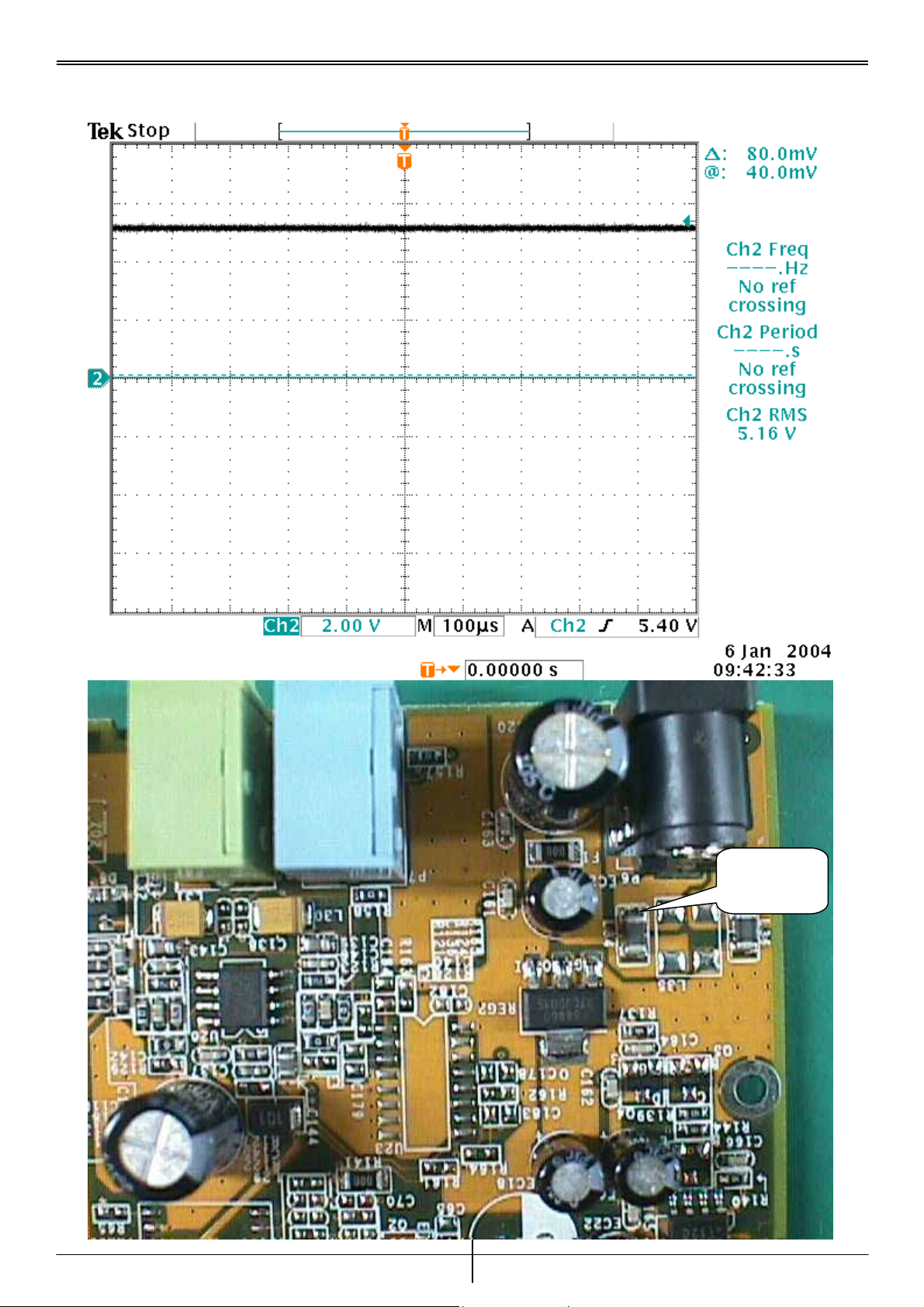
c. Check REG2 Pin 2 Signal........................................................................................................6
d. Check REG5 Pin 2 Signal........................................................................................................7
e. Check REG3 Pin 2 Signal........................................................................................................8
f. Check REG4 Pin 2 Signal.........................................................................................................9
g. Check X1,U22 Pin 26 X’TAL Signal.....................................................................................10
h. Check X2 Pin 3,U5 Pin 62,U1 Pin 41 OSC Signal................................................................11
i. Check Y301 X’TAL Signal.....................................................................................................12
j. Check U1 CLK_SAA Signal ..................................................................................................13
k. Check U1 RAM_CLK Signal................................................................................................14
Chapter 3. Troubleshooting Guide..................................................................................................15
Chapter 4. Removal and Replacement............................................................................................16
Chapter 5. Parts list.........................................................................................................................17
Chapter 6. Tools..............................................................................................................................17
Version 1.0
age 1
Page 3
Service Manual
P
Chapter 1. INTRODUCTION
a. Hardware
♦ PC586 above
♦ Connection port : VGA
b. Software
♦ Win98 above
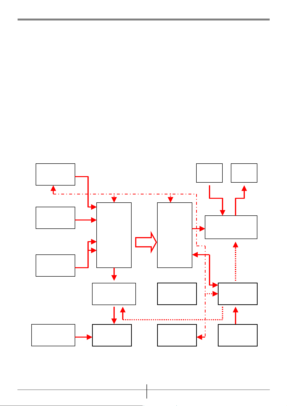
c. Block Diagram
TV VGA VGA
(Silicon Tuner) IN OUT
S-Video
Video PIP select Module
SAA-7135 processor
STV-108A
PIP
Composite & Selector
Audio Line in
Audio Switch MCU + OSD
Audio Amplifie SDRAM SM-602
2
I C BUS
Audio Selector
PC audio line in Audio out EEPROM Button input
Version 1.0
age 2
Page 4
Service Manual
P
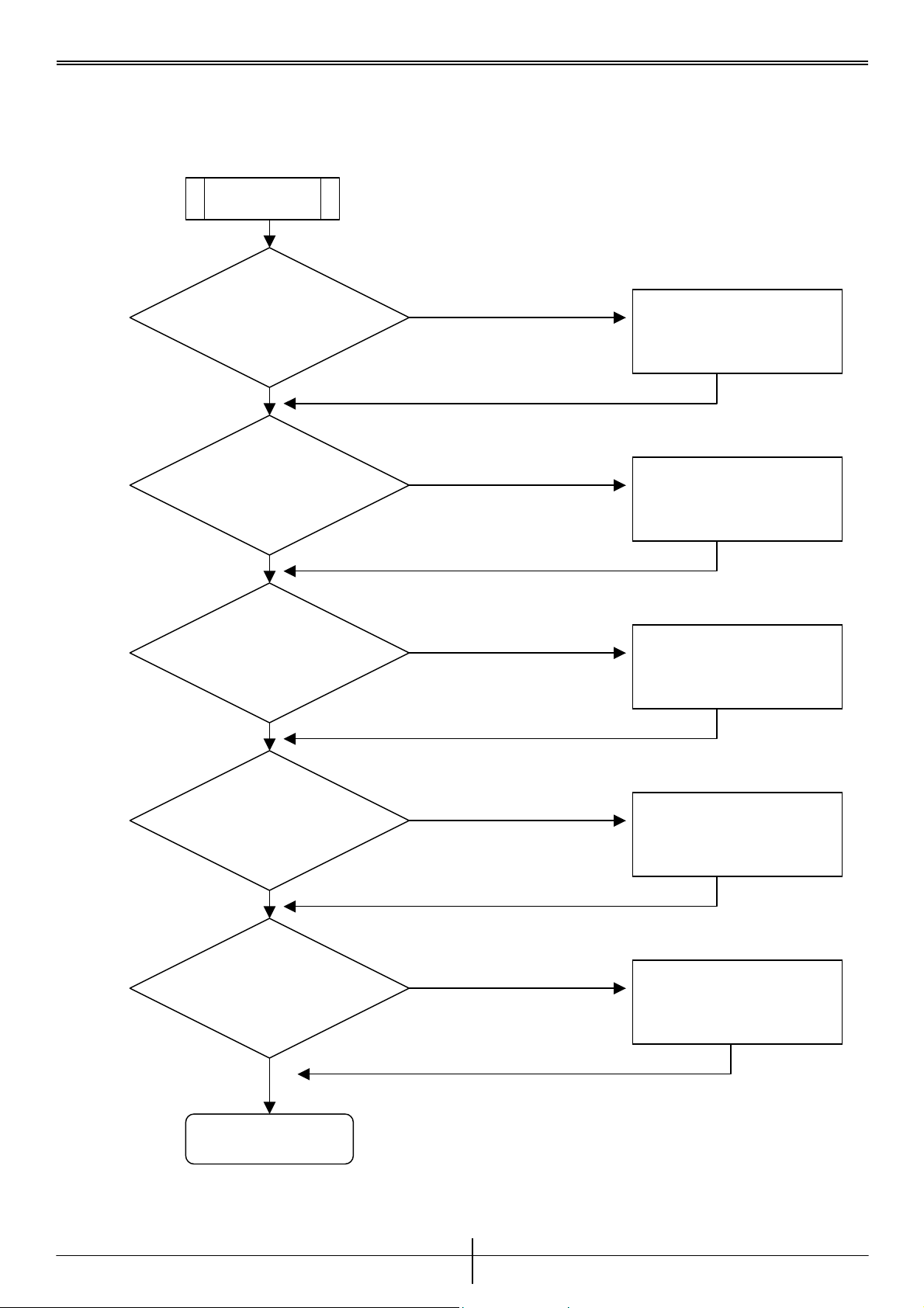
Chapter 2. Testing Procedures
a. Testing flow chart
START
Check VCC
+5V
F
REPLACE ADAPTER
T
F
Check REG2
Pin 2 +3.3V
REPLACE REG2
T
F
Check REG5
Pin 2 +2.5V
REPLACE REG5
T
F
Check REG3
Pin 2 +3.3V
REPLACE REG3
T
F
Check REG4
Pin 2 +1.8V
REPLACE REG4
T
A
Version 1.0
age 3
Page 5
Service Manual
P
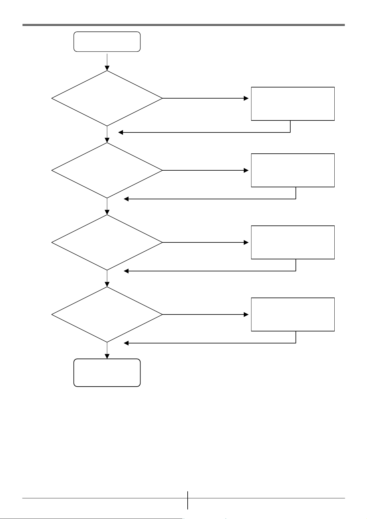
A
T
Check X1
X’TAL signal
F
REPLACE X1,U22
T
Check X2
OSC signal
F
REPLACE X2,U5,U1
T
Check Y301
X’TAL signal
F
REPLACE Y301,U301
T
Check U1
CLK signal
T
END
F
REPLACE U1
Version 1.0
age 4
Page 6
Service Manual
P
b. Check VCC +5V
L34 PIN1
Version 1.0
age 5
Page 7

Service Manual
P
6
c. Check REG2 Pin 2 Signal
REG2.PIN 2
Version 1.0
age
Page 8

Service Manual
P
7
d. Check REG5 Pin 2 Signal
REG5 PIN2
Version 1.0
age
Page 9

Service Manual
P
e. Check REG3 Pin 2 Signal
REG3 PIN2
Version 1.0
age 8
Page 10

Service Manual
P
f. Check REG4 Pin 2 Signal
REG4 PIN2
Version 1.0
age 9
Page 11

Service Manual
P
g. Check X1,U22 Pin 26 X’TAL Signal
U22 PIN26
Version 1.0
age 10
Page 12

Service Manual
P
h. Check X2 Pin 3,U5 Pin 62,U1 Pin 41 OSC Signal
U5 PIN62
U1 PIN41
Version 1.0
age 1 1
Page 13

Service Manual
P
i. Check Y301 X’TAL Signal
C322 PIN1
Version 1.0
age 12
Page 14

Service Manual
P
j. Check U1 CLK_SAA Signal
U5 PIN66
U1 PIN58
Version 1.0
age 13
Page 15

Service Manual
P
k. Check U1 RAM_CLK Signal
U1 PIN136
Version 1.0
age 14
Page 16

Service Manual
P
Chapter 3. Troubleshooting Guide
Problems Condition Probable Reasons Solutions
1. Blank Screen 1. Sound only, no picture. 1. Parts failure. Change all the parts
below
1. X2
2. REG5
3. U1
2. Buttons don’t
work
3. incorrect color
display
4. LED no lit 1. no power. 1.LED failure 1.Change LED
5. Remote not
functions
6. No TV image 1. Display malfunction. 1.TDA8275 NG 1.Change Y301
7. Black & white
image only
8. No display in
AV,SVHS
modes
9. PIP MODE
malfunction
1. Buttons malfunction. 1. Micro SW NG 1.Change Micro SW
1. VGA output malfunction. 1. Parts failure. 1.Change U15
1. Remote control
malfunction.
1. Only black and white
color in TV,AV,SVHS
modes.
1. No display in AV,SVHS
modes.
2. display correctly in TV
mode.
1. The desktop can not
work in PIP MODE
1.IR1 failure 1. .Change IR1
1.X’TAL NG 1.Change X2
1.SAA 7135 NG 1.Change U5
1.X’TAL NG 1.Change X1
Version 1.0
age 15
Page 17

Service Manual
P
6
Chapter 4. Removal and Replacement
Step Description Picture
1. Turn the
device upside
down with the
ports facing
you.
2.Remove
screws
Device before disassemble.
Remove the rubber protectors
at the corners and take out the
screws.
3.Open the
case
4. Remove
PCB from case
Remove bottom cover.
Remove the PCB by lifting it
and pulling it slightly toward
you, being careful not to
damage the LED light.
Version 1.0
age 1
Page 18

Service Manual
P
7
Chapter 5. Parts list
Description Parts number Description Parts number
U1 102100010800 REG5 101900111702
U22 102100060200 REG4 101900111707
U5 102100713500 REG2,REG3 101900886000
X1 12MHZ 201511200000
X2 OSC24.576MHZ 201522457600
Y301 16MHZ 201511600000
SW1~SW6 TACT SWITCH 201200300404
Chapter 6. Tools
1. Screwdriver cross
2. Oscilloscope
Version 1.0
age 1
 Loading...