

Page 1
Industrial
Slider
Page 2

AVVERTENZE PER L’INSTALLATORE
OBBLIGHI GENERALI PER LA SICUREZZA
1) ATTENZIONE! È importante per la sicurezza delle persone seguire attentamente tutta l’istruzione. Una errata installazione o un errato uso del prodotto
può portare a gravi danni alle persone.
2) Leggere attentamente le istruzioni prima di iniziare l’installazione del prodotto.
3) I materiali dell’imballaggio (plastica, polistirolo, ecc.) non devono essere
lasciati alla portata dei bambini in quanto potenziali fonti di pericolo.
4) Conservare le istruzioni per riferimenti futuri.
5) Questo prodotto è stato progettato e costruito esclusivamente per l’utilizzo
indicato in questa documentazione. Qualsiasi altro utilizzo non espressamente indicato potrebbe pregiudicare l’integrità del prodotto e/o rappresentare fonte di pericolo.
6) GENIUS declina qualsiasi responsabilità derivata dall’uso improprio o diverso
da quello per cui l’automatismo è destinato.
7) Non installare l’apparecchio in atmosfera esplosiva: la presenza di gas o fumi
infiammabili costituisce un grave pericolo per la sicurezza.
8) Gli elementi costruttivi meccanici devono essere in accordo con quanto
stabilito dalle Norme EN 12604 e EN 12605.
Per i Paesi extra-CEE, oltre ai riferimenti normativi nazionali, per ottenere un
livello di sicurezza adeguato, devono essere seguite le Norme sopra riportate.
9) GENIUS non è responsabile dell’inosservanza della Buona Tecnica nella costruzione delle chiusure da motorizzare, nonché delle deformazioni che
dovessero intervenire nell’utilizzo.
10) L’installazione deve essere effettuata nell’osservanza delle Norme EN 12453
e EN 12445. Il livello di sicurezza dell’automazione deve essere C+E.
11) Prima di effettuare qualsiasi intervento sull’impianto, togliere l’alimentazione
elettrica.
12) Prevedere sulla rete di alimentazione dell’automazione un interruttore
onnipolare con distanza d’apertura dei contatti uguale o superiore a 3 mm.
È consigliabile l’uso di un magnetotermico da 6A con interruzione onnipolare.
13) Verificare che a monte dell’impianto vi sia un interruttore differenziale con
soglia da 0,03 A.
14) Verificare che l’impianto di terra sia realizzato a regola d’arte e collegarvi
le parti metalliche della chiusura.
15) L’automazione dispone di una sicurezza intrinseca antischiacciamento costituita da un controllo di coppia. E' comunque necessario verificarne la sogli
di intervento secondo quanto previsto dalle Norme indicate al punto 10.
16) I dispositivi di sicurezza (norma EN 12978) permettono di proteggere eventuali aree di pericolo da Rischi meccanici di movimento, come ad Es.
schiacciamento, convogliamento, cesoiamento.
17) Per ogni impianto è consigliato l’utilizzo di almeno una segnalazione luminosa nonché di un cartello di segnalazione fissato adeguatamente sulla struttura dell’infisso, oltre ai dispositivi citati al punto “16”.
18) GENIUS declina ogni responsabilità ai fini della sicurezza e del buon funzionamento dell’automazione, in caso vengano utilizzati componenti dell’impianto non di produzione GENIUS.
19) Per la manutenzione utilizzare esclusivamente parti originali GENIUS.
20) Non eseguire alcuna modifica sui componenti facenti parte del sistema
d’automazione.
21) L’installatore deve fornire tutte le informazioni relative al funzionamento
manuale del sistema in caso di emergenza e consegnare all’Utente
utilizzatore dell’impianto il libretto d’avvertenze allegato al prodotto.
22) Non permettere ai bambini o persone di sostare nelle vicinanze del prodotto
durante il funzionamento.
23) Tenere fuori dalla portata dei bambini radiocomandi o qualsiasi altro datore
di impulso, per evitare che l’automazione possa essere azionata involontariamente.
24) Il transito tra le ante deve avvenire solo a cancello completamente aperto.
25) L’Utente utilizzatore deve astenersi da qualsiasi tentativo di riparazione o
d’intervento diretto e rivolgersi solo a personale qualificato.
26) Tutto quello che non è previsto espressamente in queste istruzioni non è
permesso
IMPORTANT NOTICE FOR THE INSTALLER
GENERAL SAFETY REGULATIONS
1) ATTENTION! To ensure the safety of people, it is important that you read
all the following instructions. Incorrect installation or incorrect use of the
product could cause serious harm to people.
2) Carefully read the instructions before beginning to install the product.
3) Do not leave packing materials (plastic, polystyrene, etc.) within reach of
children as such materials are potential sources of danger.
4) Store these instructions for future reference.
5) This product was designed and built strictly for the use indicated in this
documentation. Any other use, not expressly indicated here, could compromise the good condition/operation of the product and/or be a source of
danger.
6) GENIUS declines all liability caused by improper use or use other than that for
which the automated system was intended.
7) Do not install the equipment in an explosive atmosphere: the presence of
inflammable gas or fumes is a serious danger to safety.
8) The mechanical parts must conform to the provisions of Standards EN 12604
and EN 12605.
For non-EU countries, to obtain an adequate level of safety, the Standards
mentioned above must be observed, in addition to national legal regulations.
9) GENIUS is not responsible for failure to observe Good Technique in the
construction of the closing elements to be motorised, or for any deformation
that may occur during use.
10) The installation must conform to Standards EN 12453 and EN 12445. The safety
level of the automated system must be C+E.
11) Before attempting any job on the system, cut out electrical power.
12) The mains power supply of the automated system must be fitted with an allpole switch with contact opening distance of 3mm or greater. Use of a 6A
thermal breaker with all-pole circuit break is recommended.
13) Make sure that a differential switch with threshold of 0.03 A is fitted upstream
of the system.
14) Make sure that the earthing system is perfectly constructed, and connect
metal parts of the means of the closure to it.
15) The automated system is supplied with an intrinsic anti-crushing safety device
consisting of a torque control. Nevertheless, its tripping threshold must be
checked as specified in the Standards indicated at point 10.
16) The safety devices (EN 12978 standard) protect any danger areas against
mechanical movement Risks, such as crushing, dragging, and shearing.
17) Use of at least one indicator-light is recommended for every system, as well
as a warning sign adequately secured to the frame structure, in addition to
the devices mentioned at point “16”.
18) GENIUS declines all liability as concerns safety and efficient operation of the
automated system, if system components not produced by GENIUS are used.
19) For maintenance, strictly use original parts by GENIUS.
20) Do not in any way modify the components of the automated system.
21) The installer shall supply all information concerning manual operation of the
system in case of an emergency, and shall hand over to the user the warnings
handbook supplied with the product.
22) Do not allow children or adults to stay near the product while it is operating.
23) Keep remote controls or other pulse generators away from children, to
prevent the automated system from being activated involuntarily.
24) Transit through the leaves is allowed only when the gate is fully open.
25) The user must not attempt any kind of repair or direct action whatever and
contact qualified personnel only.
26) Anything not expressly specified in these instructions is not permitted.
CONSIGNES POUR L'INSTALLATEUR
RÈGLES DE SÉCURITÉ
1) ATTENTION! Il est important, pour la sécurité des personnes, de suivre à la
lettre toutes les instructions. Une installation erronée ou un usage erroné
du produit peut entraîner de graves conséquences pour les personnes.
2) Lire attentivement les instructions avant d'installer le produit.
3) Les matériaux d'emballage (matière plastique, polystyrène, etc.) ne doivent
pas être laissés à la portée des enfants car ils constituent des sources
potentielles de danger.
4) Conserver les instructions pour les références futures.
5) Ce produit a été conçu et construit exclusivement pour l'usage indiqué dans
cette documentation. Toute autre utilisation non expressément indiquée
pourrait compromettre l'intégrité du produit et/ou représenter une source
de danger.
6) GENIUS décline toute responsabilité qui dériverait d'usage impropre ou
différent de celui auquel l'automatisme est destiné.
7) Ne pas installer l'appareil dans une atmosphère explosive: la présence de
gaz ou de fumées inflammables constitue un grave danger pour la sécurité.
8) Les composants mécaniques doivent répondre aux prescriptions des Normes
EN 12604 et EN 12605.
Pour les Pays extra-CEE, l'obtention d'un niveau de sécurité approprié exige
non seulement le respect des normes nationales, mais également le respect
des Normes susmentionnées.
9) GENIUS n'est pas responsable du non-respect de la Bonne Technique dans la
construction des fermetures à motoriser, ni des déformations qui pourraient
intervenir lors de l'utilisation.
10) L'installation doit être effectuée conformément aux Normes EN 12453 et EN
12445. Le niveau de sécurité de l'automatisme doit être C+E.
11) Couper l'alimentation électrique avant toute intervention sur l'installation.
12) Prévoir, sur le secteur d'alimentation de l'automatisme, un interrupteur
omnipolaire avec une distance d'ouverture des contacts égale ou supérieure
à 3 mm. On recommande d'utiliser un magnétothermique de 6A avec
interruption omnipolaire.
13) Vérifier qu'il y ait, en amont de l'installation, un interrupteur différentiel avec
un seuil de 0,03 A.
14) Vérifier que la mise à terre est réalisée selon les règles de l'art et y connecter
les pièces métalliques de la fermeture.
15) L'automatisme dispose d'une sécurité intrinsèque anti-écrasement, formée
d'un contrôle du couple. Il est toutefois nécessaire d'en vérifier le seuil
d'intervention suivant les prescriptions des Normes indiquées au point 10.
16) Les dispositifs de sécurité (norme EN 12978) permettent de protéger des
zones éventuellement dangereuses contre les Risques mécaniques du
mouvement, comme l'écrasement, l'acheminement, le cisaillement.
Page 3
INDUSTRIAL SLIDER AUTOMATION
9
8
ENGLISH
These instructions apply to the following models:
INDUSTRIAL SLIDER
The INDUSTRIAL SLIDER automations for industrial sliding gates up
to 3500 kg are electromechanical operators which transmit
movement to the leaf by means of a pinion with rack coupled
in an appropriate manner to the sliding gate.
The system is guaranteed to be mechanically locked when the
motor is not in operation so a lock does not need to be installed.
The gear motors have adjustable mechanical clutches to ensure
correct use of the automation. A convenient manual release
device allows the gate to be opened in the event of a power
failure or malfunction. The electronic control unit is incorporated
in the gear motors.
The INDUSTRIAL SLIDER automations have been designed and
built for vehicle access control in industrial areas. Do not use for
any other purpose.
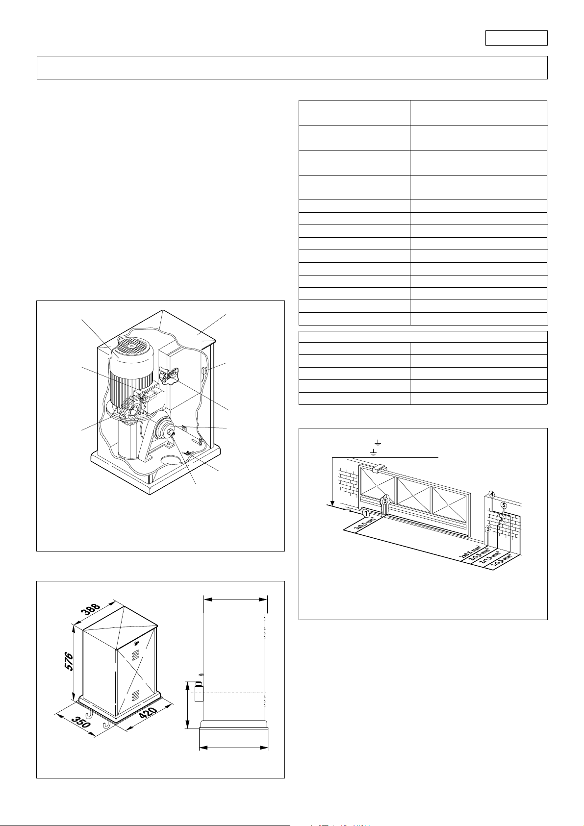
1. DESCRIPTION AND TECHNICAL SPECIFICATIONS
3
2
5
1
4
Table 1 Technical specifications
Power supply
Power consumption
Reduction ratio
No. of pinion teeth
Nominal torque
Max. thrust
Duty rating
Temperature range
Gear motor weight
Housing protection
Max. gate weight
Gate speed
Max. gate length
Clutch
Casing painting
Control unit
Limit switches
Gear dimensions LxHxD
Electric motor technical specifications
Power supply
Current
Power consumption
Motor speed rpm
3. ELECTRICAL SET-UP
380V 5x2,5 mm
RSTN
RST 220V 4x2,5 mm
230V 3ph / 400V 3ph + N (+ 6 % - 10 %) 50Hz
800W
1:30
Z12 Module 6
135 Nm
340 daN
60%
-20°C +55°C
70 kg
IP44
3500 kg
11 m/min.
20 m
Twin discs in oil bath
polyester
incorporated
mechanical
see Fig. 2
230V 3ph/400V 3ph + N (+6%-10%)
50 HzFrequency
3.5A / 2 A
750 W
1400
2
2
6
Fig. 1
7
1) Electronic control unit
2) Casing
3) Electric motor
4) Clutch adjustment screw
5) Door safety sensor
2. DIMENSIONS
6) Earthing screw
7) Manual release device
8) Mechanical limit switch with roller
9) Transmission pinion
335
1)Operator with control unit
2)Photocells
3)Key switch
4)Flashing light
5)Radio receiver
Fig. 3
4. INSTALLING THE AUTOMATION
4.1. PRELIMINARY CHECKS
For safe, correct operation of the automation, make sure that the
following requirements are met:
232
350
Values are expressed in mm.
Fig. 2
• The gate’s structure must be suitable for automation. Take
special care to ensure that the wheels are large enough to
support the full weight of the gate, that a top runner is
installed and that mechanical limit stops are fitted to prevent
the gate from coming off the runner.
• The characteristics of the ground must ensure sufficient support
for the foundation plinth.
• There must be no pipes or electrical cables in the area to be
dug for installing the foundation plinth.
5
Page 4

ENGLISH
• If the gear motor is located in a vehicle transit area, it is a good
idea to provide protection against accidental collisions.
• Check that the gear motor has an efficient earth connection.
4.2. INSTALLING THE BASE PLATE
1) The base plate must be positioned as shown in fig. 4.
For the positioning distances refer to fig. 5.
Important: The plate must be level with the middle of the pinion.
Remember to maintain a minimum distance of 10 mm between
the rack and the gate.
2) Assemble the foundation plate as shown in A, fig. 4.
3) Prepare a foundation plinth as shown in fig. 4 and install the
base plate providing one or more conduits for electrical
cables. Use a level to check that the plate is perfectly
horizontal and wait for the cement to set.
4) Set up the electrical cables for connection to the accessories
and the electricity supply as described in fig. 3. For ease of
connection, ensure that the cables protrude by about 1 m
from the hole in the base plate.
LATO USCITA PIGNONE
PINION EXIT SIDE
SEITE DES ZAHNZADES
CÔTÉ SORTIE PIGNON
LATO SALIDA PIÑÓN
rif.A
MIN. 55
MAX. 60
PIANO SUPERIORE
TOP LEVEL
OBERSEITE
DESSUS SUPÉRIEUR
SUPERFICIE SUPERIOR
Fig. 7
3) Use a level to check that the operator is perfectly horizontal
as shown in fig. 8.
4) Tighten up the four securing nuts provisionally.
5) Set up the operator for manual operation as described in
section 8.
rif.A
min. 10 mm
30 mm
25 mm
min. 25 mm
max. 55 mm
Fig. 4
Fig. 5
Fig. 8
4.4 PREPARING FOR RACK MOUNTING
Important: To mount the rack on the leaf it is necessary to
construct special supports specifically for the type of gate. Fig. 10
shows an example of "L" support. For positioning the supports refer
to figs. 5 and 9.
4.4.1 MOUNTING THE RACK
1) Slide the leaf manually to the closed position.
2) Rest the first rack element level on the pinion and weld the
support onto the gate as shown in fig. 11.
3) Move the gate manually making sure that the rack rests on
the pinion and weld the remaining supports.
4) Place another rack element end to end with the first and use
a section of rack to set the teeth of the two elements in phase
as shown in 11A.
4.3. MECHANICAL INSTALLATION
1) Remove the casing (2, fig. 1) and position the gear motor on
the foundation plate. Fit, but do not tighten, the washer, the
split washer and the nut as shown in fig. 7.
2) Adjust the height of the feet as shown in A, fig. 8 while keeping
the gear motor raised from the plate by 1 cm and maintaining
the distance from the gate shown in fig. 5.
275
190
Fig. 9
6
Page 5

5) Open the gate manually and weld the remaining supports.
Proceed in this manner for all the rack elements and supports
until the entire gate has been covered.
N.B.: Check that none of the rack elements come off the pinion
during the movement of the gate.
Important: Do not weld the rack elements together.
After installing the rack, lower the position of the gear motor by
about 4 mm (fig. 12) by adjusting the level screws (A, Fig. 8) to
ensure correct meshing with the pinion.
Screw up tightly the 4 gear motor securing nuts.
Fig. 10
Fig. 11AFig. 11
ENGLISH
Fig. 12A
When the LED of the opening travel end limit switch in the
electronic control unit goes out, advance the travel stop plate
10 mm more, and fasten it temporarily in position with two spot
welds.
4) Move the gate by hand towards its closed position, stopping
5 cm from the mechanical travel stop.
5) Slide the travel stop plate along the rack in the closing
direction.
When the LED of the closing travel end limit switch in the electronic
control unit goes out, advance the travel stop plate 10 mm more,
and fasten it temporarily in position with two spot welds.
Note: the travel stop plates may be fastened by means of screws,
if desired (fig. 12A).
The fastening slot makes it possible, if necessary, to adjust the
travel stop position.
Important: a) The limit switch must be tripped by the initial
bent part of the travel stop plate, as shown in
fig. 12A.
b) It is advisable to straighten the final bent part of
the travel stop plate, as shown in fig. 12A, in
order to prevent the plate from passing the limit
switch.
6) Lock the system (see paragraph 9).
Caution: To prevent damage to the operator and/or stoppage
of operation, leave about 5 cm between the limit switch position
and the desired closure position.
61 mm
4 mm
Z12 mod.6
Fig. 12
Check manually that the gate reaches the mechanical travel
limits correctly and that it does not encounter friction during its
travel. Do not use grease or other lubricants between the pinion
and the rack.
4.4.2. POSITIONING THE BENT TRAVEL STOP PLATES
The operator is equipped with a mechanical travel stop with roller
and trigger. The movement of the gate is stopped when a bent
travel stop plate fixed to the top of the rack operates the trigger,
tripping the microswitch (fig. 12A).
To position the two travel stop plates provided, proceed as
follows:
1) Switch on the power supply.
2) Move the gate by hand towards its open position, stopping
5 cm from the desired closure position.
3) Slide the travel stop plate along the rack in the opening
direction.
5. START-UP
Warning: Always turn off the electricity supply before carrying out
any work on the electronic control unit (connections,
programming, maintenance).
Observe points 10, 11, 12, 13 and 14 in the GENERAL SAFETY
INSTRUCTIONS.
Since the system requires two different power supplies (230 and
400 Vac), install two differential magneto-thermal circuit breakers
with adequate trip threshold up-line of the system.
Connect the earth cable to the connection on the base of the
operator. See fig. 15.
1
2
3
Fig. 15
7
Page 6

ENGLISH
The operator has two safety devices (5 , fig. 1) activated by the
front door. If either of the two safety devices are activated, the
operator is prevented from performing any operation.
As shown in Fig. 3, prepare the conduits and make the electrical
connections from the electronic control unit to the chosen
accessories.
Always route the power supply cables separately from the control
and safety cables (keyswitch, receiver, photocells, etc.). Use
separate conduits to avoid any interference.
6. SETTING THE MECHANICAL CLUTCH
To calibrate the transmitted torque adjustment system, refer to
fig. 19.
Fig. 19
1) Remove the self-locking nut using the key provided.
2) Remove the thrust ring and ring nut. Unscrew by two turns the
ring nut screwed onto the thrust ring.
3) Refit the ring and ring nut on the drive shaft. Tighten the selflocking nut until it reaches the mechanical end stop.
4) Activate the system and check that the clutch is adjusted so
as to allow the leaf to move without danger.
5) If the clutch is not adjusted correctly, repeat steps 1), 2), 3)
and 4). To increase torque, slacken the ring nut inside the ring;
to reduce torque tighten the ring nut.
6) Once the clutch has been correctly adjusted, tighten the
lateral screw on the thrust ring. This way the thrust ring and the
ring nut are held firmly together, so if the leaf has to be moved
manually (section 8), it will not be necessary to readjust the
clutch in the event of an incorrect action.
N.B.: To ensure that the clutch is always adjusted in the same way,
tighten the self-locking nut until it reaches the mechanical end
stop.
7. TESTING THE AUTOMATION
When installation is complete, affix the danger warning label to
the top of the casing (Fig. 20). Thoroughly check operation of the
automation and all connected accessories.
Give the customer the User's Guide. Explain how the gear motor
works and how it should be used correctly, and draw attention
to the potential danger zones of the automation.
8. MANUAL OPERATION
If the gate has to be operated manually due to a power failure
or malfunction of the automation, use the release device as
follows.
- Open the door in the casing using the triangular key provided
(see fig. 21).
- When the door opens, a safety sensor (5, fig. 1) prevents the
electronic control unit from operating.
- Using the key provided, undo the self-locking nut until the
clutch is released as shown in fig. 22.
- Close the door and open or close the gate manually.
Fig. 20
9. RETURN TO NORMAL OPERATION
- Turn off the power supply to the system.
- Open the door in the casing using the triangular key provided
(see fig. 21).
- Turn the self-locking nut shown in fig. 22 anticlockwise until it
reaches the mechanical end stop.
- Close the door.
- Turn the power supply to the system back on.
N.B.: To ensure that the clutch is always adjusted in the same way,
tighten the self-locking nut until it reaches the mechanical end
stop.
10. MAINTENANCE
When performing maintenance always check that the anticrushing clutch is correctly regulated and that the safety devices
operate correctly.
11. REPAIRS
For repairs contact an authorised repair centre.
Fig. 21
Fig. 22
8
Page 7

DICHIARAZIONE CE DI CONFORMITÁ PER MACCHINE
(DIRETTIVA 89/392 CEE, ALLEGATO II, PARTE B)
Fabbricante: GENIUS s.r.l.
Indirizzo: Via Padre Elzi, 32
Dichiara che: L'Attuatore mod. INDUSTRIAL SLIDER
• è costruito per essere incorporato in una macchina o
• è conforme ai requisiti essenziali di sicurezza
e inoltre dichiara che non è consentito mettere in servizio il
macchinario fino a che la macchina in cui sarà incorporata o
di cui diverrà componente sia stata identificata e ne sia stata
dichiarata la conformità alle condizioni della Direttiva 89/392/
CEE e successive modifiche trasposta nella legislazione
nazionale dal DPR n° 459 del 24 Luglio 1996.
Grassobbio, 1 Marzo 2002
24050 - Grassobbio
BERGAMO - ITALIA
per essere assemblato con altri macchinari per
costituire una macchina ai sensi della Direttiva 89/
392 CEE, e successive modifiche 91/368/CEE, 93/44/
CEE, 93/68/CEE;
delle seguenti altre direttive CEE:
73/23 CEE e successiva modifica 93/68/CEE.
89/336 CEE e successiva modifica 92/31 CEE e
93/68/CEE
L’Amministratore Delegato
D. Gianantoni
EC MACHINE DIRECTIVE COMPLIANCE DECLARATION
(DIRECTIVE 89/392 EEC, APPENDIX II, PART B)
Manufacturer: GENIUS s.r.l.
Address: Via Padre Elzi, 32
Hereby declares that: the INDUSTRIAL SLIDER
• is intended to be incorporated into machinery, or to
• complies with the essential safety requirements in the
and furthermore declares that unit must not be put into service
until the machinery into which it is incorporated or of which it
is a component has been identified and declared to be in
conformity with the provisions of Directive 89/392 ECC and
subsequent amendments enacted by the national
implementing legislation.
Grassobbio, 1 March 2002
24050 - Grassobbio
BERGAMO - ITALY
be assembled with other machinery to constitute
machinery in compliance with the requirements of
Directive 89/392 EEC, and subsequent amendments
91/368 EEC, 93/44 EEC and 93/68 EEC;
following EEC Directives:
73/23 EEC and subsequent amendment 93/68 EEC.
89/336 EEC and subsequent amendments 92/31 EEC
and 93/68 EEC.
Managing Director
D. Gianantoni
DÉCLARATION CE DE CONFORMITÉ
(DIRECTIVE EUROPÉENNE "MACHINES" 89/392/CEE,
ANNEXE II, PARTIE B)
Fabricant: GENIUS s.r.l.
Adresse:
Déclare d’une part
et d’autre part
qu’il est formellement interdit de mettre en fonction l'automatisme en
question avant que la machine dans laquelle il sera intégrée ou dont
il constituera un composant ait été identifiée et déclarée conforme
aux exigences essentielles de la directive européenne "machines"
89/392/CEE, et décrets de transposition de la directive.
Grassobbio, le 1 Mars 2002
Via Padre Elzi, 32
24050 - Grassobbio
BERGAMO - ITALIE
que l'automatisme mod. INDUSTRIAL SLIDER
• est prévue soit pour être incorporée dans une machine,
soit pour être assemblée avec d’autres composants ou
parties en vue de former une machine selon la directive
européenne "machines" 89/392 CEE, modifiée 91/368
CEE, 93/44 CEE, 93/68 CEE.
• satisfait les exigences essentielles de sécurité des
directives CEE suivantes:
73/23 CEE, modifiée 93/68 CEE.
89/336 CEE, modifiée 92/31 CEE et 93/68 CEE.
L’Administrateur Délégué
D. Gianantoni
DECLARACIÓN DE CONFORMIDAD CE PARA MÁQUINAS
(DIRECTIVA 89/392 CEE, ANEXO II, PARTE B)
Fabricante: GENIUS s.r.l.
Dirección: Via Padre Elzi, 32
Declara que: El equipo automático mod. INDUSTRIAL SLIDER
Asimismo, declara que no está permitido poner en marcha el
equipo si la máquina en la cual será incorporado, o de la cual
se convertirá en un componente, no ha sido identificada o no
ha sido declarada su conformidad a lo establecido por la
Directiva 89/392 CEE y sus sucesivas modificaciones, y a la ley
que la incorpora en la legislación nacional.
Grassobbio, 1º de Marzo de 2002.
24050 - Grassobbio
BERGAMO - ITALIA
• Ha sido construido para ser incorporado en una
máquina, o para ser ensamblado con otros
mecanismos a fin de constituir una máquina con
arreglo a la Directiva 89/392 CEE y a sus sucesivas
modificaciones 91/368 CEE, 93/44 CEE y 93/68 CEE.
• Cumple los requisitos esenciales de seguridad
establecidos por las siguientes directivas CEE:
73/23 CEE y sucesiva modificación 93/68 CEE,
89/336 CEE y sucesivas modificaciones 92/31 CEE y
93/68 CEE.
Administrador Delegado
D. Gianantoni
EG-KONFORMITÄTSERKLÄRUNG ZU MASCHINEN
(gemäß EG-Richtlinie 89/392/EWG, Anhang II, Teil B)
Hersteller: GENIUS s.r.l.
Adresse: Via Padre Elzi, 32
erklärt hiermit, daß: der Antrieb Mod. INDUSTRIAL SLIDER
und erklärt außerdem, daß die Inbetriebnahme solange
untersagt ist, bis die Maschine, in welche diese Maschine
eingebaut wird oder von der sie ein Bestandteil ist, den
Bestimmungen der Richtlinie 89/392 EWG sowie deren
nachträglichen Änderungen entspricht.
Grassobbio, 1 März 2002
24050 - Grassobbio
BERGAMO - ITALIEN
• zum Einbau in eine Maschine oder mit anderen
Maschinen zu einer Maschine im Sinne der Richtlinie
89/392 EWG und deren Änderungen 91/368 EWG,
93/44 EWG, 93/68 EWG vorgesehen ist.
• den wesentlichen Sicherheitsbestimmungen
folgender anderer EG-Richtlinien entspricht:
73/23 EWG und nachträgliche Änderung 93/68 EWG
89/336 EWG und nachträgliche Änderung 92/31 EWG
sowie 93/68 EWG
Der Geschäftsführer
D. Gianantoni
Timbro rivenditore: / Distributor’s stamp: / Timbre de l’agent: /
Sello del revendedor: / Fachhändlerstempel:
Le descrizioni e le illustrazioni del presente manuale non sono
impegnative. GENIUS si riserva il diritto, lasciando inalterate le
caratteristiche essenziali dell’apparecchiatura, di apportare in
qualunque momento e senza impegnarsi ad aggiornare la
presente pubblicazione, le modifiche che essa ritiene convenienti per miglioramenti tecnici o per qualsiasi altra esigenza di
carattere costruttivo o commerciale.
The descriptions and illustrations contained in the present
manual are not binding. GENIUS reserves the right, whils leaving the main features of the equipments unaltered, to undertake any modifications to holds necessary for either technical
or commercial reasons, at any time and without revising the
present publication.
Les descriptions et les illustrations du présent manuel sont
fournies à titre indicatif. GENIUS se réserve le droit d’apporter à
tout moment les modifications qu’elle jugera utiles sur ce
produit tout en conservant les caractéristiques essentielles,
sans devoir pour autant mettre à jour cette publication .
Las descripciones y las ilustraciones de este manual no
comportan compromiso alguno. GENIUS se reserva el derecho,
dejando inmutadas las características esenciales de los
aparatos, de aportar, en cualquier momento y sin
comprometerse a poner al día la presente publicación, todas
las modificaciones que considere oportunas para el
perfeccionamiento técnico o para cualquier otro tipo de
exigencia de carácter constructivo o comercial.
Die Beschreibungen und Abbildungen in vorliegendem
Handbuch sind unverbindlich. GENIUS behält sich das Recht
vor, ohne die wesentlichen Eigenschaften dieses Gerätes zu
verändern und ohne Verbindlichkeiten in Bezung auf die
Neufassung der vorliegenden Anleitungen, technisch bzw,
konstruktiv / kommerziell bedingte Verbesserungen
vorzunehmen.
GENIUS s.r.l.
Via Padre Elzi, 32
24050 - Grassobbio
BERGAMO-ITALY
tel. 0039.035.4242511
fax. 0039.035.4242600
info@geniusg.com
www.geniusg.com
I0211 REV.1
 Loading...