

Page 1

BLIZZARD 500 C
https://smartel.ua
BLIZZARD 900 C
Page 2

© Copyright FAAC S.p.A. dal 2016. Tutti i diritti riservati.
https://smartel.ua
Nessuna parte di questo manuale può essere riprodotta, archiviata, distribuita a terzi
né altrimenti copiata, in qualsiasi formato e con qualsiasi mezzo, sia esso elettronico,
meccanico o tramite fotocopia, senza il preventivo consenso scritto di FAAC S.p.A.
Tutti i nomi e i marchi citati sono di proprietà dei rispettivi fabbricanti.
I clienti possono effettuare copie per esclusivo utilizzo proprio.
Questo manuale è stato pubblicato nel 2016.
© Copyright FAAC S.p.A. from 2016. All rights reserved.
No part of this manual may be reproduced, archived, distributed to third parties nor
copied in any other way, in any format and with any means, be it electronic, mechanical
or by photocopying, without prior written authorisation by FAAC S.p.A.
All names and trademarks mentioned are the property of their respective manufacturers.
Customers may make copies exclusively for their own use.
This manual was published in 2016.
© Copyright FAAC S.p.A. depuis 2016. Tous droits réservés.
Aucune partie de ce manuel ne peut être reproduite, archivée ou distribuée à des tiers
ni copiée, sous tout format et avec tout moyen, qu’il soit électronique, mécanique ou
par photocopie, sans le consentement écrit préalable de FAAC S.p.A.
Tous les noms et les marques cités sont la propriété de leurs fabricants respectifs.
Les clients peuvent faire des copies pour leur usage exclusif.
Ce manuel a été publié en 2016.
© Copyright FAAC S.p.A. del 2016. Todos los derechos están reservados.
No puede reproducirse, archivarse, distribuirse a terceros ni copiarse de ningún modo,
ninguna parte de este manual, con medios mecánicos o mediante fotocopia, sin el
permiso previo por escrito de FAAC S.p.A.
Todos los nombre y las marcas citadas son de propiedad de los respectivos fabricantes.
Los clientes pueden realizar copias para su uso exclusivo.
Este manual se ha publicado en 2016.
© Copyright FAAC S.p.A. van 2016. Alle rechten voorbehouden.
Niets uit deze handleiding mag gereproduceerd, gearchiveerd, aan derden openbaar
gemaakt of op andere wijze gekopieerd worden, in om het even welke vorm en met geen
enkel middel, noch elektronisch, mechanisch of via fotokopiëren, zonder schrfitelijke
toestemming vooraf van FAAC S.p.A.
Alle vermelde namen en merken zijn eigendom van de respectievelijke fabrikanten.
De klanten mogen kopieën maken die enkel voor eigen gebruik bestemd zijn.
Dez handleiding werd in 2016 gepubliceerd.
© Copyright FAAC S.p.A. 2016. Tüm hakları saklıdır.
Bu kılavuzunun hiç bir bölümünün, FAAC S.p.A. tarafından yazılı izin
olmadan yeniden üretilmesi, arşivlenmesi, üçüncü şahıslara dağıtılması ve de hiç bir
formatta ve hiç bir şekilde, elektronik, mekanik veya fotokopi yöntemiyle çoğaltılması
yasaktır.
Belirtilen tüm isimler ve markalar üreticinin mülkiyetindedir.
Müşteriler sadece kendi kullanımları için kopyalama işlemi yapabilirler.
Bu kılavuz 2015 yılında yayınlanmıştır.
BLIZZARD 500-900 C 2 532103 - Rev.B
Page 3

CONTENTS
https://smartel.ua
1. INTRODUCTION TO THIS INSTRUCTION MANUAL .......... 4
1.1 Meaning of Symbols Used ....................................... 4
2. SAFETY RECOMMENDATIONS ..................................5
2.1 Installer safety .................................................... 5
2.2 Transport and storage ............................................ 5
2.3 Unpacking and handling ........................................ 6
2.4 Disposal of the product .......................................... 6
3. BLIZZARD 500-900 C .............................................. 6
3.1 Intended use ...................................................... 6
3.2 Limitations of use ................................................. 6
3.3 Prohibited uses ................................................... 6
3.4 Emergency Use ................................................... 7
3.5 Product Warnings ................................................. 7
3.6 Product Identification ............................................ 7
3.7 Technical Characteristics ......................................... 7
3.8 Component Identification ....................................... 8
3.9 Dimensions ........................................................ 8
4. INSTALLATION REQUIREMENTS ................................ 9
4.1 Mechanical Requirements ....................................... 9
4.2 Electrical System .................................................. 9
4.3 Example System .................................................10
5. INSTALLATION ................................................... 10
5.1 Tools Required ...................................................10
5.2 Installation Dimensions .........................................11
5.3 Base plate .........................................................12
5.4 Fastening the Gear Motor.......................................12
5.5 Manual Operation ...............................................13
5.6 Installing the Rack ...............................................13
5.7 Adjustments and Checks .......................................16
6. ELECTRONIC BOARD ............................................ 17
6.1 Terminal boards and connectors ...............................18
6.2 Photocells and safety devices ..................................19
7. START-UP.......................................................... 20
7.1 Power supply and earthing .....................................20
7.2 LEDs Check .......................................................20
7.3 Installation of the Limit Switches ..............................21
7.4 Programming ....................................................22
7.5 Direction of movement check ..................................24
7.6 Final Operations .................................................24
8. MAINTENANCE ................................................... 25
8.1 Scheduled Maintenance ........................................25
9. OPERATING LOGICS ............................................. 27
10. INSTRUCTIONS FOR USE ..................................... 30
10.1 Safety recommendations......................................30
10.2 Product Warnings ..............................................30
10.3 Emergency Use .................................................30
10.4 Manual Operation ..............................................30
EU DECLARATION OF CONFORMITY
The Manufacturer
Company name: FAAC S.p.A. Soc. Unipersonale
Address: Via Calari, 10 - 40069 Zola Predosa BOLOGNA - ITALY
hereby declares under his sole responsibility that the following product:
Description: Gear motor for sliding gates
Model: BLIZZARD 500 C; BLIZZARD 900 C.
Complies with the following relevant Union harmonization legislations:
2014/30/EU
2011/65/EU
Furthermore, the following harmonised standards have been applied:
EN61000-6-2:2005
EN61000-6-3:2007 + A1:2011
Bologna, Italy, 30-09-2016 CEO
DECLARATION OF INCORPORATION FOR PARTLY
COMPLETED MACHINERY
(2006/42/EC ANNEX II P.1, B)
Manufacturer and person authorised to draft the applicable technical documentation
Company name: FAAC S.p.A. Soc. Unipersonale
Address: Via Calari, 10 - 40069 Zola Predosa BOLOGNA - ITALY
Hereby declares that the partly completed machinery:
Description: Gear motor for sliding gates
Model: BLIZZARD 500 C; BLIZZARD 900 C.
the following essential requirements of the Machinery Directive 2006/42/EC
(including all applicable amendments) have been applied and fulfilled:
1.1.2, 1.1.3, 1.1.5, 1.1.6, 1.2.1, 1.2.3, 1.2.5, 1.2.6, 1.3.1,
1.3.2, 1.3.4, 1.3.6, 1.3.9, 1.4.1, 1.4.2.1, 1.5.1, 1.5.2,
1.5.5, 1.5.6, 1.5.7, 1.5.8, 1.5.10, 1.5.11, 1.6.1, 1.6.4,
1.7.1, 1.7.2, 1.7.3, 1.7.4.2, 1.7.4.3
and that the relevant technical documentation has been compiled in compliance
with part B of Annex VII.
Furthermore, the following harmonised standards have been applied:
EN12100:2010
EN13849-1:2015
EN13849-2:2012
Other applied standards:
EN12453:2000
Undertakes to transmit by mail or by e-mail, in response to a reasoned request by
the national authorities, relevant information on the partly completed machinery.
It is also declared that the partly completed machinery identified above may not be commissioned until the final machine - into which it will be incorporated - has been declared
complaint with the provisions of the above mentioned Machine Directive 2006/42/EC.
Bologna, Italy, 30-09-2016 CEO
ENGLISH
ENGLISH
Translation of the original instructions
Translation of the original instructions
BLIZZARD 500-900 C 3 532103 - Rev.B
Page 4

1. INTRODUCTION TO THIS INSTRUCTION MANUAL
https://smartel.ua
This manual provides the correct procedures and requirements for
installing BLIZZARD 500-900 C and maintaining it in a safe condition.
When drafting the manual, the results of the risk assessment conducted by FAAC S.p.A. on the entire product life cycle have been taken
into account in order to implement effective risk reduction measures.
The following stages of the life cycle of the product have been considered:
- Delivery/handling
- Assembly and installation
- Set-up and commissioning
- Operation
- Maintenance/troubleshooting
- Disposal at the end of the product’s life cycle
Risks arising from installation and using the product have been taken
into consideration; these include:
- Risks for the installation/maintenance technician (technical
ENGLISH
ENGLISH
Translation of the original instructions
Translation of the original instructions
personnel)
- Risks for the user of the automation system
- Risks to product integrity (damage)
In Europe, the automation of a gate falls under the Machinery Directive
2006/42/EC and the corresponding harmonised standards. Anyone
automating a gate (new or existing) is classified as the Manufacturer
of the Machine. They are therefore required by law, among other
things, to carry out a risk analysis of the machine (automatic gate in
its entirety) and take protective measures to fulfil the essential safety
requirements specified in Annex I of the Machinery Directive.
This manual also contains general information and guidelines,
which are purely illustrative and not exhaustive, in order to facilitate
the activities carried out by the Manufacturer of the Machine in all
respects with regard to carrying out the risk analysis and drafting
the instructions for use and maintenance of the machine. It should
be clearly understood that FAAC S.p.A. accepts no liability for the
reliability and/ or completeness of the above instructions. As such,
the manufacturer of the machine must carry out all the activities required by the Machinery Directive and the corresponding harmonised
standards on the basis of the actual condition of the locations and
structures where the product BLIZZARD 500-900 C will be installed,
prior to commissioning the machine. These activities include the
analysis of all the risks associated with the machine and subsequent
implementation of all safety measures intended to fulfil the essential
safety requirements.
This manual contains references to European standards. The automation of a gate must fully comply with any laws, standards and
regulations applicable in the country where installation will take place.
FIGURE E.g.: 1-3 see Figure 1 - detail 3.
TABLE E.g.: 1 see Table 1.
§
CHAPTER/SECTION E.g.: §1.1 see section 1.1.
2 Symbols: safety indications (ISO 7010)
GENERAL HAZARD
Personal injury hazard or risk of damage to components.
ELECTRIC SHOCK HAZARD
Risk of electric shock from live parts.
CRUSHING HAZARD, DANGER TO THE MUSCULOSKELETAL SYSTEM
Risk of musculoskeletal crushing - Personal injury hazard when manually
lifting heavy loads.
BURN HAZARD
Risk of burns due to the presence of high-temperature parts.
CRUSHING HAZARD
Risk of crushing to the hands/feet due to the presence of heavy parts.
CUTTING/AMPUTATION/PUNCTURE HAZARD
Cutting hazard due to the presence of sharp components or the use of
pointed/sharp tools (drill).
SHEARING HAZARD
Risk of shearing from moving parts.
IMPACT/CRUSHING HAZARD
Risk of impact or crushing due to moving parts.
FORKLIFT TRUCK IMPACT HAZARD
Risk of collision/impact with forklift trucks.
Unless otherwise specified, the measurements provided in the instruc-
tions are in mm.
1.1 MEANING OF SYMBOLS USED
1 Symbols: notes and warnings on the instructions
WARNING ELECTRIC SHOCK HAZARD - The operation or stage described
must be performed following the supplied instructions and applicable safety
F
regulations.
WARNING, PERSONAL INJURY HAZARD OR RISK OF DAMAGE TO COMPO
NENTS - The operation or stage described must be performed following the
!
supplied instructions and applicable safety regulations.
WARNING - Details and specifications which must be respected in order to
ensure that the system operates correctly.
RECYCLING AND DISPOSAL - The materials used in manufacturing, the batteries
and any electronic components must not be sent to landfill. They must be taken
to authorised recycling and disposal centres.
BLIZZARD 500-900 C 4 532103 - Rev.B
3 Symbols: personal protective equipment
Personal protective equipment must be worn to protect against hazards (e.g. crushing,
cutting, shearing etc.):
Obligatory use of mask/goggles to protect the eyes from the risk of shards
produced when using drills or welding equipment.
Obligatory use of work gloves.
Obligatory use of safety footwear.
Page 5
2. SAFETY RECOMMENDATIONS
https://smartel.ua
This product is placed onto the market as “partly completed machinery”, therefore it cannot be commissioned until the machine in which
it will be incorporated has been identified and declared to conform
to the Machinery Directive 2006/42/EC by the actual Manufacturer.
Incorrect installation and/or incorrect use of the product might cause
!
serious harm to people. Read and comply with all the instructions
before starting any activity on the product. Keep these instructions
for future reference.
Perform installation and other activities adhering to the sequences
provided in the instructions manual.
Always comply with all the requirements contained in the instructions
and warning tables at the beginning of the paragraphs. Always
comply with the safety recommendations.
Only the installer and/or maintenance technician is authorised to
work on the automation components. Do not modify the original
components in any way.
Close off the work site (even temporarily) and prevent access/transit. EC countries must comply with the legislation that transposes
the European Construction Site Directive 92/57/EC.
The installer is responsible for the installation/testing of the automation and for completing the Register of the system.
The installer must prove or declare to possess technical and professional proficiency to perform installation, testing and maintenance
activities according to the requirements in these instructions.
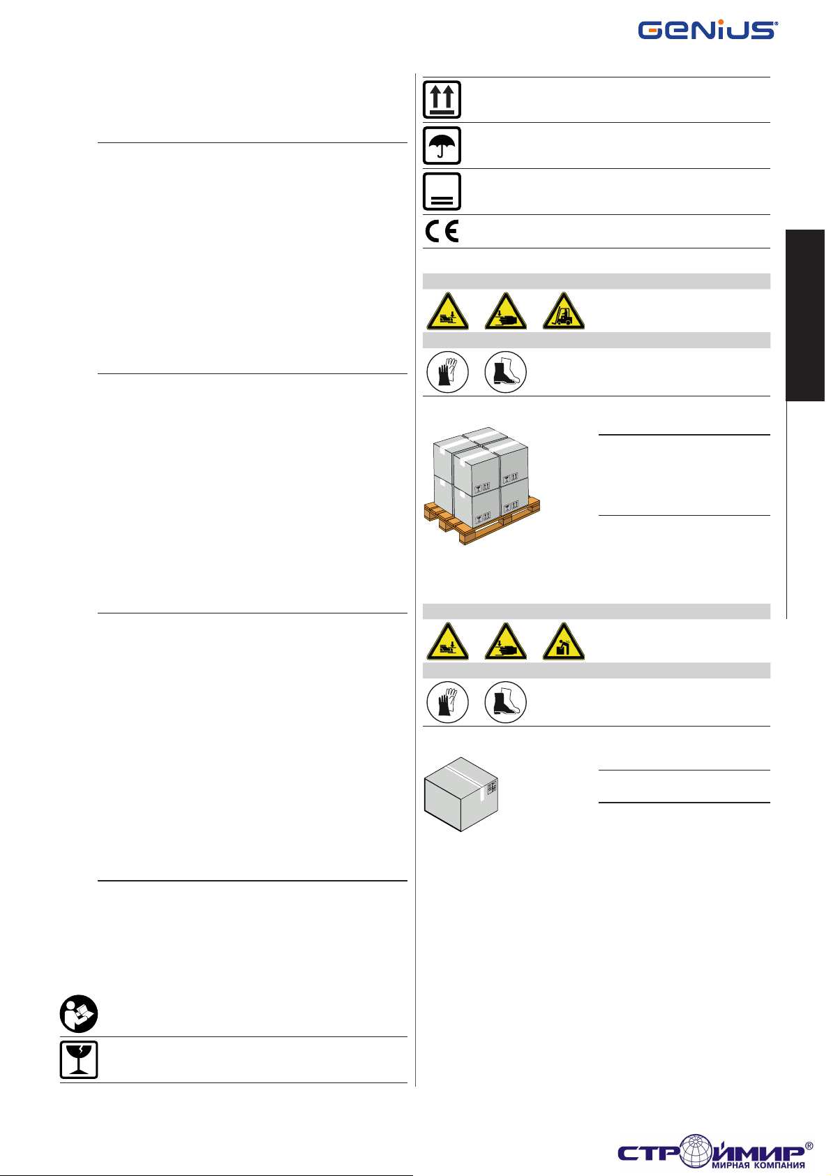
Up indication.
Keep away from water and moisture.
3
Maximum number of stacked packages.
CE marking.
SUPPLY ON PALLETS
RISKS
PERSONAL PROTECTIVE EQUIPMENT
Follow the instructions on the packag-
!
ing during handling.
Use a forklift or pallet truck, following
safety regulations to avoid the risk of
impacts or collisions.
ENGLISH
ENGLISH
2.1 INSTALLER SAFETY
Installation activities require special work conditions to reduce to the
minimum the risks of accidents and serious damage. Furthermore,
the suitable precautions must be taken to prevent risks of injury to
persons or damage.
The installer must be in good physical and mental condition, aware
!
of and responsible for the hazards that may be generated when using
the product.
The work area must be kept tidy and must not be left unattended.
Do not wear clothes or accessories (scarves, bracelets, etc.) that may
get caught in moving parts.
Always wear the personal protective equipment recommended for the
type of activity to be carried out.
The required level of workplace lighting must be equal to at least
200 lux.
Operate CE marked machinery and equipment in compliance with
the manufacturer's instructions. Use work instruments in good
conditions.
Use the transport and lifting equipment recommended in the instructions manual.
Use safety-compliant portable ladders of adequate size, fitted with
anti-slip devices at the top and bottom, equipped with retainer hooks.
2.2 TRANSPORT AND STORAGE
4 Symbols: warnings on packaging.
SINGLE PACKAGE
RISKS
PERSONAL PROTECTIVE EQUIPMENT
Follow the instructions on the packag-
!
ing during handling.
STORAGE
Store the product in its original packaging, in closed and dry premises,
protected from the sun and free from dust and aggressive substances.
Protect from mechanical stress. If stored for more than 3 months,
regularly check the condition of the components and the packaging.
- Storage temperature: 5°C to 30°C.
- Percentage of humidity: 30% to 70%.
Translation of the original instructions
Translation of the original instructions
Read the instructions.
Handle with care. Fragile parts.
BLIZZARD 500-900 C 5 532103 - Rev.B
Page 6

2.3 UNPACKING AND HANDLING
https://smartel.ua
RISKS
PERSONAL PROTECTIVE EQUIPMENT
1. Open the package.
The gear motor casing is not fixed.
2. Remove the magnetic limit switches and the bag of accessories.
3. Remove the casing.
Do not lift the gear motor by the electronic board.
!
4. Lift the gear motor, holding it by the base.
ENGLISH
ENGLISH
Check that all components are present and intact 2.
5. Dispose of the packaging materials.
3. BLIZZARD 500900 C
The packaging materials (plastic, polystyrene etc.) must not be left
!
within reach of children, as they are potential hazards.
When you have finished with them, dispose of the packaging in the
appropriate containers, as per applicable waste disposal regulations.
2.4 DISPOSAL OF THE PRODUCT
After dismantling the product, dispose of it in compliance with
Standards in force.
The constructive components and materials, batteries and electronic
components must not be disposed of with household waste but delivered to authorised disposal and recycling facilities.
3.1 INTENDED USE
GENIUS BLIZZARD 500-900 C series gear motors are designed to
operate horizontal sliding gates for residential use (including in
apartment complexes).
One gear motor must be installed for each sliding gate section. The
gate must be moved via a rack.
Installations of BLIZZARD 500-900 C must be used for vehicular traffic.
To operate the gate manually, follow the instructions in § 5.5.
Translation of the original instructions
Translation of the original instructions
Any other use which is not expressly specified in these instructions is
!
prohibited and could affect the integrity of the product and/or represent
a source of danger.
3.2 LIMITATIONS OF USE
The gate must fall within the dimensional and weight limitations
indicated in the technical data section. Obey the limitations on
frequency of use listed in the technical data section.
Using the product in any configuration other than that provided for
by FAAC S.p.A. is prohibited. It is prohibited to modify any product
component.
The presence of weather conditions such as snow, ice and strong
wind, even when occasional, could compromise correct automation,
affect the integrity of the components and represent a potential
source of danger.
If a pedestrian access gate is integrated in the sliding gate section,
motorised movement must be disabled when the pedestrian gate
is not closed.
BLIZZARD 500-900 C is not designed as a security (break-in protection) system.
Implementing automation requires the installation of the necessary
safety devices, identified by the installer through an appropriate risk
assessment of the installation site.
3.3 PROHIBITED USES
- Uses other than the intended use are prohibited.
- It is prohibited to install the automation system outside of the
limits specified in the Technical Data and Installation Requirements sections.
- It is prohibited to install the automation system on escape routes.
- It is prohibited to install the automation system to create fire
doors.
- It is prohibited to install the automation system in environments
which represent an explosion or fire hazard: the presence of
flammable gases or fumes represents a serious safety hazard
(the product is not 94/9/EC ATEX certified).
- It is prohibited to power the system with energy sources other
than those specified.
- It is prohibited to integrate commercial systems and/or equip-
ment other than those specified, or use them for purposes not
envisaged and authorised by the corresponding manufacturers.
- It is prohibited to use and/or install accessories which have not
been specifically authorised by FAAC S.p.A.
- It is prohibited to use the automation system before performing
commissioning.
- It is prohibited to use the automation system in the presence of
faults which could compromise safety.
- It is prohibited to use the automation system with the fixed and/
or mobile guards removed or altered.
- Do not allow water jets of any type or size to come into direct
contact with the gear motor.
- Do not expose the gear motor to corrosive chemical or atmos-
pheric agents.
- Do not use the automation system unless the area of operation
is free of persons, animals or objects.
- Do not remain in or walk/drive through the area of operation of
the automation system while it is moving.
- Do not try to prevent the movement of the automation system.
- Do not climb on, hold onto or let yourself be pulled by the
gate. Do not climb onto or sit on the gear motor.
- Do not allow children to approach or play in the area of operation
of the automation system.
- Do not allow the control devices to be used by anyone who is
not specifically authorised and trained to do so.
- Do not allow the control devices to be used by children or persons
with mental and physical deficiencies unless they are supervised
by an adult who is responsible for their safety.
During manual operation, gently guide the gate the whole way, do not
!
push it and let it slide freely.
BLIZZARD 500-900 C 6 532103 - Rev.B
Page 7

3.4 EMERGENCY USE 3.6 PRODUCT IDENTIFICATION
https://smartel.ua
In any malfunction, emergency or fault, disconnect the power supply of the automation. If the conditions allow the leaf to be safely
moved manually, use the MANUAL OPERATION; otherwise, keep the
automation out of service until it is restored/repaired.
In case of a fault, the automation must be restored/repaired must
only be carried out by the INSTALLER/MAINTENANCE TECHNICIAN.
FAAC S.p.A. Soc. Unipersonale
Via Calari, 10 - 40069 Zola Predosa BOLOGNA
Italy
••••
3.5 PRODUCT WARNINGS
Risk of fingers and hands being trapped between the rack, pinion and
casing (2).
••••••
••••••
MM/YY PROG
••••
•••
••••
•••
Sales code
Product name
IDENTIFICATION NUMBER
••••
Month/year of production +
progressive number for the
month of production
E.g.:
0115 0001
1
3.7 TECHNICAL CHARACTERISTICS
The GENIUS BLIZZARD 500 C and BLIZZARD 900 C series gear motors
are equipped with an electronic board that controls their automatic
operation (§ 6). The travel of the gate is determined by two magnetic
limit switches. Movement cannot be reversed: To operate the gate
manually, follow the instructions in § 5.5. The board may be equipped
with optional accessories:
- obstacle recognition encoder (optional accessory in some mo-
dels);
- GENIUS 5-pin radio receiver.
ENGLISH
ENGLISH
Translation of the original instructions
Translation of the original instructions
5 Technical Data
BLIZZARD 500 C BLIZZARD 900 C
Supply voltage 230 V~ (+6%…-10%) 50 Hz 115 V~ (+6%…-10%) 60 Hz 230 V~ (+6%…-10%) 50 Hz 115 V~ (+6%…-10%) 60 Hz
Electric motor Asynchronous single phase Asynchronous single phase Asynchronous single phase Asynchronous single phase
Start-up capacitor 10 µF 40 µF 12.5 µF 50 µF
Max power 360 W 350 W 540 W 610 W
Thermal protection 140 °C (automatic rearming) 140 °C (automatic rearming) 140 °C (automatic rearming) 140 °C (automatic rearming)
Max thrust force 390 N 250 N 590 N 540 N
Starting thrust force 300 N 220 N 410 N 380 N
Pinion Z16 Module 4 Z16 Module 4 Z16 Module 4 Z16 Module 4
Max sliding gate section length 15 m 15 m 15 m 15 m
Max. sliding gate section weight* 500 kg 500 kg 900 kg 900 kg
Sliding gate section speed 12 m/min 14 m/min 12 m/min 14 m/min
Ambient operating temperature -20 °C - +55 °C -20 °C - +55 °C -20 °C - +55 °C -20 °C - +55 °C
Type of use Residential/Condominium Residential/Condominium Residential/Condominium Residential/Condominium
Continuous use time (ROT)** 22 min 37 min 23 min 23 min
Ingress Protection IP44 IP44 IP44 IP44
Dimensions (LxDxH) 297x170x256 297x170x256 297x170x256 297x170x256
Gear motor weight 9.2 kg 9.2 kg 10 kg 10 kg
Electronic board SPRINT 382 SPRINT 383 SPRINT 382 SPRINT 383
* In the case of a cantilever gate, the maximum weight of the sliding gate section is reduced by 30%
** 20°C, FO=20 (§ 7.4).
BLIZZARD 500-900 C 7 532103 - Rev.B
Page 8

3.8 COMPONENT IDENTIFICATION
https://smartel.ua
ENGLISH
ENGLISH
4
3
5
INSTALLATION ACCESSORIES WHICH ARE NOT SUPPLIED
21
1
2
3
6
4
5
Translation of the original instructions
Translation of the original instructions
6 Components
1 Case and danger symbol
2 Hardware/accessories
3 Electric motor
4 Magnetic limit stop sensor
5 Electronic board
6 Magnetic limit switches
7 Release device
8 Start-up capacitor
9 Earth connection
10 Power cable clamp
11 Z16 Module 4 pinion
3
7 Installation Accessories
1 Base plate with mounting hardware
2 Steel rack
3 Spacers for steel rack (to be screwed or welded)
4 Nylon rack
5 Mounting hardware for nylon rack
7
10
1198
2
3.9 DIMENSIONS
297
BLIZZARD 500-900 C 8 532103 - Rev.B
256
170
4
Page 9

4. INSTALLATION REQUIREMENTS
https://smartel.ua
4.1 MECHANICAL REQUIREMENTS
The mechanical structural components must comply with the requirements of EN 12604
Before installing the automation system, the suitability of the mechanical requirements must be established, and the necessary work
to reach them performed.
The essential mechanical requirements are as follows:
Solid ground to support the weight of the gate, the structures present
!
and the gear motor. There must be no chance of water accumulating
in the installation area. Flat, horizontal paving in the area of movement of the sliding gate section.
Structure (columns, guides, mechanical strikers, sliding gate section)
must be solid and there must be no risk of detachment or collapse,
taking into consideration the weight of the sliding gate section, force
applied by wind and the forces generated by the gear motor. Perform
structural calculations where necessary.
No signs of corrosion or cracking in the structure.
Sliding gate section perfectly vertical in all movement positions with
regular, uniform movement without friction.
Appropriate devices must be installed to prevent the gate from falling.
There must be a lower horizontal sliding guide in good condition; this
must be straight, with no deformations, and must be solidly fastened to
the ground and free of obstacles along its entire length. The sliding
gate section must remain in any position in which it is placed without
moving. Presence of guide wheels on the ground, with diameter
appropriate for the size and length of the sliding gate section and
profile section matching the sliding guide. The number and position
of the wheels must ensure adequate and constant distribution of the
weight at all times.
Presence of upper containing guide to prevent vertical oscillation of
the sliding gate section. The sliding gate section must not under any
circumstances come out from its guides and fall. Wheels, rollers and
bearings in good condition, lubricated and free from play or friction.
External mechanical limit stops to limit the travel of the sliding gate
section when opening and closing. The stops must be suitably sized
and solidly fastened so that they resist any impact of the sliding gate
section in the event of improper use (gate pushed and left to slide
freely). The mechanical limit stops must be positioned at 50 mm
beyond the stop position of the sliding gate section, and must ensure
that the sliding gate section remains inside its sliding guides.
The thresholds and protrusions of the paving must be appropriately
shaped in order to prevent the risk of sliding or slipping.
Safety precaution between the wall (or other fixed element) and the
furthest protruding part of the open gate to protect against the risk
of persons becoming trapped/crushed. Alternatively, check that the
opening force required falls within the maximum permissible limits
according to applicable standards and legislation.
Safety devices installed between the fixed and moving parts to prevent
against the risk of hands being trapped. Alternatively, apply protective elements preventing the introduction of fingers.
Safety element between the paving and lower edge of the sliding gate
section, along its entire path, providing protection from the risk of feet
becoming caught in and crushed beneath the wheels. Alternatively,
apply protective elements preventing the introduction of feet.
No sharp edges or protruding parts should be present to ensure there
is no cutting, hooking or perforation hazard. Alternatively, eliminate
or protect any sharp edges and protruding parts.
No slots or openings should be present on the sliding gate section or the
fencing to prevent the creation of a shearing hazard. Alternatively,
apply protective mesh to any such openings. The mesh should be
sufficiently fine to prevent introduction of body parts requiring protection, in relation to the distance between the fixed and moving parts.
and EN 12605.
For the minimum dimensions to prevent crushing/shearing of body
!
parts, refer to EN 349. For the safety distances required to prevent
danger zones being reached, refer to ISO 13857.
There should be a solid surface on the sliding gate section sufficiently
large to attach the rack to.
If the area of installation gives rise to the risk of impact by vehicles, provide for an appropriate protective structure to protect the gear motor.
4.2 ELECTRICAL SYSTEM
Always shut off the power supply before performing any work. If the
F
disconnect switch is not in view, apply a warning sign stating “WARNING - Maintenance in Progress”.
The electrical system must comply with applicable legislation in the
!
country of installation.
Use components and materials with CE marking which are compli-
ant with the Low Voltage Directive 2014/35/EU and EMC Directive
2014/30/EU.
The power supply line for the automation system must be fitted with
a 6 A omnipolar circuit breaker with a contact opening distance of at
least 3 mm, with breaking capacity which meets code.
The power supply for the automation system must be fitted with a
30 mA RCD.
The metal parts of the structure must be earthed. Check that the
protective earthing system complies with applicable regulations in
the country of installation.
The electrical cables of the automation system must be laid in appropriate conduits, which may be rigid or flexible, above or below ground;
the size and insulation class must conform with applicable legislation.
Use separate conduits for power supply and low-voltage control cables.
Check buried cable plans to ensure that there are no other electrical
cables in proximity to the planned digging/drilling locations to prevent
the risk of electrocution.
Check that there are no pipes in the vicinity as well.
It is recommended to install a flashing light in a visible position to warn
when the gate is moving.
The control accessories must be positioned in a location which is not
hazardous to the user and is also accessible with the gate open. It
is advisable to position the control accessories within the field of view
of the automation system; this is obligatory when operator presence
is required for the controls.
If an emergency stop button has been installed, it must be EN13850
compliant.
The following limits apply with regard to the height from the ground:
- Control accessories = minimum 150 cm
- Emergency button = maximum 120 cm
ENGLISH
ENGLISH
Translation of the original instructions
Translation of the original instructions
BLIZZARD 500-900 C 9 532103 - Rev.B
Page 10

4.3 EXAMPLE SYSTEM
https://smartel.ua
The example system is a purely illustrative and not exhaustive representation of BLIZZARD 500-900 C.
8
4
5
2
7
ENGLISH
ENGLISH
3
1
5. INSTALLATION
Translation of the original instructions
Translation of the original instructions
5.1 TOOLS REQUIRED
Use appropriate tools and equipment in working environments which
!
comply with applicable legislation.
8 Symbols: work tools
HEX SPANNER of size indicated
2x17; 13; 10; 8
TORQUE WRENCH - if necessary for safety, a torque wrench and the
TIGHTENING TORQUE will be specified E.g. 6 mm hex spanner set to 2.5 Nm
x.x Nm
2.5 Nm
6
6
1
1 Mains power supply 3 x 1.5mm
2 Circuit breaker
3 Junction box
4 Blizzard gear motor
5 Photocell TX
6 Photocell RX
7 Key switch
8 Flashing Light
TAPE MEASURE
SCREW CLAMP
WELDING EQUIPMENT (for steel rack to be welded on)
ANGLE GRINDER
0123456
CALLIPER
2
5
ELECTRICIAN'S SCISSORS
HSS DRILL BIT of specified sizes
6.5; 5.5; 3.6
THREAD CUTTER of specified sizes (for steel rack to be screwed on)
M8
SPIRIT LEVEL
BLIZZARD 500-900 C 10 532103 - Rev.B
WIRE STRIPPER/TERMINAL CRIMPER
FLAT SCREWDRIVER of the size(s) indicated
2.5
TORX SCREWDRIVER of the size(s) indicated (electronic board)
T20; T15
Page 11

5.2 INSTALLATION DIMENSIONS
https://smartel.ua
POSITIONING THE BASE PLATE
95
90°
0-50
CENTRELINE DISTANCES
83
288
50
132
6
Opening to the leftOpening to the right
260
50
132
36 49
ø29
288
90°
0-50
7
ENGLISH
ENGLISH
Translation of the original instructions
Translation of the original instructions
8
POSITIONING THE RACK
60
Foundation
8-18
Nylon rack
BLIZZARD 500-900 C 11 532103 - Rev.B
14
9
Page 12

Foundation
https://smartel.ua
90
8-18
ENGLISH
ENGLISH
Steel rack
5.3 BASE PLATE
RISKS
PERSONAL PROTECTIVE EQUIPMENT
Before proceeding, check that the necessary conduits are in place
(§ 4.3-5).
The base plate and corresponding hardware are accessories which are
not included.
1. Assemble the base plate as shown in 11; tighten the supplied
Translation of the original instructions
Translation of the original instructions
M10 nuts and locknuts, using two hex spanners.
2. Pour a slab, with reference to 6 and 7 in § 5.2 and 12.
3. Take the cable conduits out from the hole (12-1) and install
the base plate.
Do not bury the base plate in the concrete.
4. Use a spirit level to check that the slab is horizontal, making any
corrections before the concrete goes off (12).
2x17
14
10
30
0123456
11
172
1
50
5.4 FASTENING THE GEAR MOTOR
RISKS
PERSONAL PROTECTIVE EQUIPMENT
Wait for the concrete to cure fully before proceeding.
Lift the gear motor, holding it by the base.
!
1. Pass the cables through the two holes on the gear motor (13-1).
2. Position the gear motor, lining up the slots and the screws on the
plate (13-2).
3. Pass the cables through the supplied cable glands, then insert the
cable glands in the holes (13-3).
If one of the two holes will not have cables running through it, insert
!
the plastic cable gland whole.
BLIZZARD 500-900 C 12 532103 - Rev.B
328
12
Page 13

4. Bring the base of the gear motor to 18mm from the base plate
https://smartel.ua
using the four support nuts (14-1).
5. Fit four M10 locknuts and four washers, supplied with the base
plate, as in 14-2.
6. Ensure there is 13.5mm between the pinion and the sliding gate
section (§ 5.2-9-10).
7. Use a spirit level to check that the gear motor is horizontal (14):
make any adjustments with the support nuts (14-1).
8. Provisionally tighten the four locknuts using two hex spanners
(14-1-2).
5.5 MANUAL OPERATION
Shut off the power to the system and ensure that the automation
!
system is stopped before performing manual movement operations
and restoring automatic operation.
A lock with personalised key is available as an optional accessory.
MANUAL RELEASE
1. Open the plastic cap on the release device (15-1).
2. Turn the lock clockwise using a coin or your personalised key
(15-1).
3. Turn the knob clockwise (15-2).
RESTORING AUTOMATIC OPERATION
1. Turn the knob anticlockwise.
2. Turn the lock anticlockwise.
3. Manually move the gate until the mechanical system engages.
3 1
2
2
18
13
ENGLISH
ENGLISH
5.6 INSTALLING THE RACK
RISKS
PERSONAL PROTECTIVE EQUIPMENT
The rack installation accessories contain screws for aluminium or steel
sliding gate sections. Use specific screws for other materials.
Do not use grease or other lubricants.
Release the gear motor and close the gate manually (§ 5.5).
STEEL RACK WITH SPACERS TO BE WELDED ON
Do not weld the rack components to the spacers or to each other.
1. Install the spacers and screws in the upper part of the slots
(16-1): This will allow future adjustments if the rail is lowered.
2. Rest the assembled component on the pinion.
3. Use a screw clamp to fasten the section to the sliding gate section,
1
2x17
0123456
12
14
15
1
Translation of the original instructions
Translation of the original instructions
BLIZZARD 500-900 C 13 532103 - Rev.B
13
16
Page 14

then use a spirit level to check it is level (17).
https://smartel.ua
4. Weld the spacer to the sliding gate section (17-1).
5. Move the sliding gate section forward, checking that the section
rests on the pinion.
6. Check the level, then weld the other two spacers, repeating the
operations in steps 5 and 6.
7. If necessary, install another rack section, as in step 1.
8. Rest the section on the pinion, bringing it up to the previous one;
use a third section, screw clamps and a spirit level to line up the
teeth and check it is level (18).
9. Weld the spacers, repeating the operations in points 5, 6 and 7.
10. Add other rack sections until the entire length of the sliding gate
section is covered.
11. If the final section is too long, cut it with an angle grinder near
one of the slots (19).
ENGLISH
ENGLISH
1
17
Translation of the original instructions
Translation of the original instructions
18
19
BLIZZARD 500-900 C 14 532103 - Rev.B
Page 15

STEEL RACK WITH SPACERS TO BE SCREWED ON
https://smartel.ua
1. Rest a rack section on the pinion (20).
2. Position the spacers in the upper part of the slots
(20-1): This will allow future adjustments if the rail is lowered.
3. Use a screw clamp to fasten the assembly to the sliding gate sec-
tion, then use a spirit level to check it is level (20).
4. Mark the point to drill into the sliding gate section (20-1).
Drill with a 6.5mm bit and use an M8 thread cutter to tap the
hole. Screw in the screw for the spacer with the corresponding
washer (20-2).
5. Move the sliding gate section forward, checking that the section
rests on the pinion.
6. Screw in the other two spacers, repeating the operations in steps
5 and 6.
7. If necessary, use another rack section; rest it on the pinion, bring-
ing it up to the previous one; use a third section, screw clamps
and a spirit level to line up the teeth and check it is level (21).
8. Install the section, repeating the operations in points 5, 6 and 7.
9. Add other rack sections until the entire length of the sliding gate
section is covered.
10. If the final section is too long, cut it with an angle grinder near
one of the three slots (22).
NYLON RACK AND MOUNTING HARDWARE
1. Rest a rack section on the pinion (23).
2. Use a screw clamp to fasten the assembly to the sliding gate sec-
tion, then use a spirit level to check it is level (23).
3. Mark the drill point on the sliding gate section, in the upper part
of the slot (23-1): This will allow future adjustments if the rail
is lowered.
4. If the thickness of the tubular section is less than 5mm, screw in
the self-tapping screw with its washer; if the thickness of the tubular section is greater than 5mm, drill with a 5.5mm bit then use
a 6.3x25 hex-head self-tapping screw instead of the self-tapping
screw (23-2).
5. Move the sliding gate section forward, checking that the section
rests on the pinion.
6. Check the level, then screw in the other two screws, repeating the
operations in steps 4, 5 and 6.
1
2
6.5
6.5
M8
M8
13
13
20
21
ENGLISH
ENGLISH
Translation of the original instructions
Translation of the original instructions
22
1
2
5.5 10
BLIZZARD 500-900 C 15 532103 - Rev.B
23
Page 16

7. If necessary, use another section of rack; rest it on the pinion and
https://smartel.ua
connect it to the previous one and use a spirit level to check it is
level (24).
8. Install the section, repeating the operations in points 4, 5, 6 and 7.
9. Add other rack sections until the entire length of the sliding gate
section is covered.
10. If the final section is too long, cut it with an angle grinder near
one of the three slots (25).
5.7 ADJUSTMENTS AND CHECKS
RISKS
PERSONAL PROTECTIVE EQUIPMENT
ENGLISH
ENGLISH
Translation of the original instructions
Translation of the original instructions
The operations described in this section are fundamentally important
to the integrity and operation of the gear motor.
1. When you have installed the rack, lower the gear mo-
tor by 1.5mm (26-1), using the four support nuts
(27-1).
2. Check that the gear motor is level using a spirit level (27).
3. Tighten the four upper locknuts to a minimum torque of 40Nm
(27-2), using a hex spanner and a torque wrench.
4. Move the gate by hand and check that:
- There is 1.5 mm between the teeth of the rack and pinion along
the travel
- The rack remains engaged with the pinion along its travel
(26-2)
- The sliding gate section and gear motor do not touch at any point
- There is no friction.
5.5
10
1.5
24
25
1
26
2
1
0123456
40
Nm
17
BLIZZARD 500-900 C 16 532103 - Rev.B
27
2
Page 17

6. ELECTRONIC BOARD
https://smartel.ua
J2
J5
DISPLAY
LED
ENCODER
LIMITS
COM
FCA
FCC
+ -
FCA
FCC
J3
ENCODER
8.8.
F
OPEN
OPEN
J1
FSW
B
FSW
A
123456789101112
OPEN A
OPEN B
OP
CL
FSW OP
FSW CL
STOP
EDGE
SAFE
STOP
EDGE
TX-FSW
W.L.
F2
J6
13 14 1615 17
COM
OPEN
CLOSENLAMP
J4
J7
PE N L
PENL
F1
ENGLISH
ENGLISH
{
24 V
500 mA
max
KEY:
J1 Terminal board for accessories
J2 Connector for GENIUS 5-pin receiver
J3 Rapid connector for encoder
J4 Rapid connector for start-up capacitor
J5 Rapid connector for the magnetic limit switch sensor
J6 Terminal board for motor and flashing light
J7 Terminal board for main power supply
F1 Fuse for main power supply
F2 Fuse for accessories power supply
9 Technical Data
SPRINT 382 (230 V~) SPRINT 383 (115 V~)
Mains power supply 230 V~ (+6%…-10%) 50 Hz 115 V~ (+6%…-10%) 60 Hz
Max power 10 W 10 W
Max. motor power 1000 W 1200 W
Max. accessories load 24 V
F1 5 A 10 A
F2 800 mA 800 mA
Ambient operating temperature -20 °C - +55 °C -20 °C - +55 °C
Flashing Light 230 V~ - 60 W 115 V~ - 60 W
"
500 mA 500 mA
LED:
FCA Limit switch 1
FCC Limit switch 2
OPEN B Partial opening command
OPEN A Total opening command
FSW OP Opening photocells
FSW CL Closing photocells
STOP Automation stop
EDGE SAFE N.C. contact for sensitive edges
ENCODER Incremental encoder
CAP
M
60 W max
NL
6 A
28
Translation of the original instructions
Translation of the original instructions
BLIZZARD 500-900 C 17 532103 - Rev.B
Page 18

6.1 TERMINAL BOARDS AND CONNECTORS
https://smartel.ua
Do not exceed the maximum load of the outputs.
J1
Terminal board for connecting the inputs and outputs (29).
10 J1 - Inputs and outputs
INPUTS
1 OPEN A N.O. contact; if active, it commands the total opening of the gate.
If multiple contacts are used, they must be connected in parallel
(30).
2 OPEN B N.O. contact; if active, it commands the partial opening of the gate.
If multiple contacts are used, they must be connected in parallel
(30).
3 FSW OP N.C. contact for photocells during opening (§ 6.2).
4 FSW CL N.C. contact for photocells during closing (§ 6.2).
5STOPN.C. stop contact (§ 6.2).
6 EDGE N.C. contact for sensitive edges (§ 6.2).
ENGLISH
ENGLISH
OUTPUTS:
7-8 - Negative for accessories.
9-10 + Positive for accessories (24 V
11 TX-FSW Fail-safe Test Output. Provides a negative pole for accessories supply
(100 mA max). It can be used to carry out a functional test of the
safety devices connected to the inputs FSW OP, FSW CL and EDGE. If
the test fails, the gear motor does control the movement.
Please refer to § 6.2 e § 7.4-15.
"
/500 mA max).
J1
123456789101112
OPEN A
OPEN B
FSW OP
FSW CL
STOP
EDGE
24 V
500 mA
max
2.5
TX-FSW
W.L.
{
29
12 W.L. Programmable output (100 mA max). When active, it provides a
negative for accessories. Default: indicator lamp (§ 7.4-15-SP).
J2
Rapid connector for inserting the GENIUS 5-pin radio receiver (optional accessory). Plug in the receiver only when the board is not powered.
J3
Translation of the original instructions
Translation of the original instructions
Rapid connector for inserting the encoder (optional accessory in
some models).
J4
Rapid connector for inserting the start-up capacitor. Alternatively, the
capacitor can be connected across terminals 14 and 15 of J6.
J5
Rapid connector for inserting the magnetic limit stop sensor.
J6
Terminal board for connecting the motor and flashing light (31).
The cable of the electric motor is connected during production.
11 J6 - Motor and Flashing Light
MOTOR OUTPUT:
13 COM Common Grey
14 OPEN Opening Black
15 CLOSE Closing Brown
FLASHING LIGHT OUTPUT:
16 N Neutral
17 LAMP Flashing lamp phase (230/115 V~): output active
during movement and during the pre-flashing set
in Programming (§ 7.4-15-PF).
Example of N.O. contacts connected in parallel
Example of N.C. contacts connected in series
J6
13 14 1615 17
COM
OPEN
CLOSENLAMP
M
60W max
2.5
30
31
BLIZZARD 500-900 C 18 532103 - Rev.B
Page 19

6.2 PHOTOCELLS AND SAFETY DEVICES
https://smartel.ua
The maximum current on terminal 11 is 100 mA: if the consumption
is greater, replace it with a negative pole for accessories supply and
do not enable the Fs and SA functions in Advanced Programming.
The contacts described in this paragraph are N.C.
57
611
STOP
32 - If active, it prevents the gear motor from operating. If multiple
contacts are used, they must be connected in series (30). If no
contact is used, bridge terminals 5 and 7-8.
EDGE
33 - If active, reverses the movement for 2 seconds and stops
the gear motor. It is usually used for connecting sensitive edges. If
multiple contacts are used, they must be connected in series (30).
If no contact is used, bridge terminals 6 and 11.
PHOTOCELLS DURING OPENING FSW OP
34 - If active, they trip during the opening movement of the gate;
the outcome depends on a function in Advanced Programming
(§ 7.4-15-oP). If multiple contacts are used, they must be connected
in series (36). If no photocells are used, bridge terminals 3 and 11.
PHOTOCELLS DURING CLOSING FSW CL
35 - If active, they trip during the closing movement of the gate;
the outcome depends on a function in Advanced Programming
(§ 7.4-15-Ph). If multiple contacts are used, they must be connected
in series (37). If no photocells are used, bridge terminals 4 and 11.
PHOTOCELLS DURING OPENING AND CLOSING
38 shows an example of a pair of photocells when opening and
closing. Their effects are described in § 9.
NO SAFETY CONTACT
If no safety contact is used, bridge the terminals as shown in 39.
32 33
3
RX TX
1
2
3
4
7
5
9
7
9
11
9
7
9
1
2
34 35
3
RX
1
2
3
4
5
1
2
4
RX
1
2
3
4
5
11
4
RX TX
1
2
9
3
4
7
5
9
TX
1
11
2
9
1
2
3
7
4
5
9
RXTX
TX
11
1
2
9
1
2
36
11
9
ENGLISH
ENGLISH
Translation of the original instructions
Translation of the original instructions
1
11
2
9
34
7
9
RX TX
1
2
3
4
5
34567
1
2
3
7
4
9
5
RXTX
1
11
2
9
37
38
11
39
BLIZZARD 500-900 C 19 532103 - Rev.B
Page 20

7. STARTUP
https://smartel.ua
During operation there is a risk of fingers and hands being trapped
!
between the rack, pinion and casing.
The body of the electric motor can reach high temperatures during
operation.
If the encoder is installed (42), make sure that it is connected to
the board and activate the relative parameter in advanced programming
(§ 7.4-15-EC).
The flashing light, if connected to the board, indicates that the gate
is moving.
7.1 POWER SUPPLY AND EARTHING
RISKS
ENGLISH
ENGLISH
Disconnect power to the system before making the connections and
F
before removing the plastic cover of the electronic board. Before
switching power on, make sure that you have replaced the plastic
cover. Do not remove the earthing wire that is connected to terminal
PE of J7 (40-1).
J7
3
2
8
2.5
1
NLPE
4
40
1. Crimp the electric motor and system earth wires together, using
the supplied terminal (40-2).
2. Install the M5 nut, washer and terminal supplied onto the gear
motor earth connection (40-3). Tighten the nut.
3. Connect the phase wires and neutral to terminals L and N respec-
tively of J7 (40-4).
12J7 - Power supply
PE Earth: do not remove the wire.
N Neutral
Translation of the original instructions
Translation of the original instructions
L Phase
Secure the mains power supply wires using the appropriate clamp
!
(41-1).
4. Switch on power to the system.
7.2 LEDS CHECK
1. Move the gate to its half-travel position.
2. Check that the status of the LEDS is the same as that shown in
13. If it is not, check the connections (§ 6).
13 LEDs Check
STATUS MEANING
FCA
FCC
OPEN B
OPEN A
FSW OP
FSW CL
STOP
EDGE SAFE
ENCODER
/
§ 7.3
§ 7.3
Partial opening command not active
Total opening command not active
Opening photocells not engaged
Closing photocells not engaged
Stop not active
Edge not active
Flashing when moving
1
41
ENCODER
42
Key:
= LED off = open contact
= LED on = closed contact
BLIZZARD 500-900 C 20 532103 - Rev.B
Page 21

7.3 INSTALLATION OF THE LIMIT SWITCHES
https://smartel.ua
RISKS
PERSONAL PROTECTIVE EQUIPMENT
OPENING TO THE RIGHT (43)
STATUS LED FCA LED FCC
CLOSING LIMIT SWITCH ENGAGED
NO LIMIT SWITCH ENGAGED
OPENING LIMIT SWITCH ENGAGED
OPENING TO THE LEFT (44)
STATUS LED FCA LED FCC
CLOSING LIMIT SWITCH ENGAGED
NO LIMIT SWITCH ENGAGED
OPENING LIMIT SWITCH ENGAGED
Key:
= LED off = limit switch engaged
= LED on = limit switch disengaged
1. Move the gate to the closed position by hand.
2. Position the closing magnetic limit switch (45-1) on the rack
and look for the point at which the FCC LED turns off .
3. Mark the centre of the limit switch slots on the rack; manually
open the gate by 1m.
4. Drill a 3.6mm diameter hole corresponding to the central points
of the slots. Fasten the limit switch using two 3.9x16 self-tapping
screws and two washers (supplied) (45-2).
5. Manually move the gate back into its stop position when closed
and check that the FCC LED turns off. Otherwise, adjust the position of the limit switch using the slots.
6. Move the gate to the open position by hand.
7. Position the opening magnetic limit switch (46-1) on the rack
and look for the point at which the FCA LED turns off.
8. Mark the centre of the limit switch slots on the rack; manually
close the gate by 1m.
9. Drill a 3.6mm diameter hole corresponding to the central points
of the slots. Fasten the limit switch using two 3.9x16 self-tapping
screws and two washers (supplied) (46-2).
10. Manually move the gate to its open position and check that the
FCA LED turns off. Otherwise, adjust the position of the limit switch
using the slots.
OPENING LIMIT SWITCH
CLOSING LIMIT SWITCH
3.6
2.5
CLOSING LIMIT SWITCH
43
OPENING LIMIT SWITCH
ENGLISH
ENGLISH
44
1
Translation of the original instructions
Translation of the original instructions
2
45
BLIZZARD 500-900 C 21 532103 - Rev.B
3.6
2.5
1
2
46
Page 22

7.4 PROGRAMMING
https://smartel.ua
The electronic board contains two Programming menus: Basic and
Advanced.
In order to save the modifications made to the functions, scroll through
the menu until reaching gate status (St). If the mains power supply fails
before the modifications are saved, all the modifications will be lost.
To reset the default values for all the functions, open the EDGE contact
(EDGE SAFE LED off) and press the +, - and F buttons simultaneously
for 5 seconds.
BASIC PROGRAMMING
1. To access the menu, press and hold down button F: the display
shows the first function (LO).
The display continues to show the name of the function as long as
button F remains pressed.
2. Release button F: the display shows the value of the function.
3. Press the + or - buttons to modify the value of the function.
ENGLISH
ENGLISH
4. Press and hold down button F to go to the next function.
ADVANCED PROGRAMMING
1. To access the menu, press and hold down button F and then press
the + button: the display shows the first function (bO).
2. Release the + button whilst keeping button F pressed.
The display continues to show the name of the function as long as
button F remains pressed.
3. Release button F: the display shows the value of the function.
4. Press the + or - buttons to modify the value of the function.
5. Press and hold down button F to go to the next function.
Translation of the original instructions
Translation of the original instructions
14 Basic Programming
BASIC PROGRAMMING Default
Operating logics (§ 9):
LO
A = Automatic
AP = Automatic Step-by-Step
S = Automatic “Safety”
E = Semi-automatic
EP = Semi-automatic Step-by-Step
C = Dead Man
b = Semi-automatic “B”
bC = Mixed (b during opening / C during closing).
Pause time:
PA
This has an effect only if an automatic logic has been selected. Adjustable from 0 to 59, in 1 second steps. The display subsequently
changes to minutes and tens of seconds, separated by a point, in
10 second steps up to a maximum of 4.1 minutes.
E.g. 2.5=2 min. and 50 sec.
Force:
FO
Regulates the thrust of the gear motor.
01 = Minimum power
50 = Maximum power
Opening direction:
dI
Indicates the gate opening movement, using the body of the gear
motor as a reference point (§ 7.3).
-3 = Opening movement towards the right
3- = Opening movement towards the left
Gate status:
St
Exit from programming function and view status.
00 = Closed
01 = When opening
02 = Stopped
03 = Open
04 = Open in pause
05 = Fail-safe Test failed (§ 6.1-10, § 6.2)
06 = When closing
07 = When reversing
08 = Photocells tripped
EP
2.0
20
-3
BLIZZARD 500-900 C 22 532103 - Rev.B
15 Advanced Programming
ADVANCED PROGRAMMING Default
Maximum torque at initial thrust:
bO
If active, the motor operates at maximum power as soon as movement starts and ignores the FO function. This is useful with heavy
sliding gate sections.
Y = Active
no = Disabled
Final braking:
br
If active, it sets a braking stroke to ensure that the gate stops immediately when the gate engages the opening or closing limit switch.
If decelerations have been set, braking starts when they end.
00 = Braking disabled.
The braking time can be adjusted from 01 to 20, in 0.1 second steps.
E.g. 10=1 second.
Y
05
Page 23

ADVANCED PROGRAMMING Default
https://smartel.ua
Fail-safe:
FS
If this function is active, it enables a functional test of the photocells
before any movement of the gate occurs (§ 6.1-10, § 6.2).
If the test fails, the gear motor does not control the movement.
Y = Active
no = Disabled
Safe:
SA
If active and FS=Y, it enables a functional test of the safety devices
connected to the EDGE terminal before every gate movement
(§ 6.1-10).
Y = Active
no = Disabled
Pre-flashing:
PF
If active, it sets a 5 second pre-flashing on the LAMP output
(§ 6.1-11).
no = disabled
oP = only before opening
CL = only before closing
OC = before every movement
W.L.: (§ 6.1-10)
SP
Do not exceed the maximum load of the output
"
- 3 W). If necessary, use a relay and a power
(24 V
supply that is external to the board.
00 = standard indicator lamp (on during opening, when open
and open in pause; flashing during closing; off when gate closed).
From 01 to 4.1 = timed output. E.g. courtesy light: The time can
be adjusted from 0 to 59, in 1 second steps and subsequently from
1.0 to 4.1 in 10 second steps.
E1 = electric lock command before the opening movement.
E2 = electric lock command before opening and closing move-
ments.
E3 = traffic light function: the output is active when the gate is
open and open in pause. It is disabled 3 seconds before the closing
manoeuvre starts, during which there are 3 seconds of pre-flashing
on the LAMP output (§ 6.1-11). Disabled during closing and
when the gate is closed.
E4 = traffic light function: the output is active only in the closing
state.
Closing photocells logic:
Ph
Sets the tripping mode of the photocells during closing (FSW CL).
Y = Stop and reverse to opening when disengaged.
no = Immediate reverse to opening
Opening photocells logic:
oP
Sets the tripping mode of photocells during opening (FSW OP).
Y = Immediate reverse to closing
no = Stop and reverse to opening when disengaged
Encoder:
EC
The encoder operates as an anti-crushing device: if the gate
strikes an obstacle, it reverses the gate movement for 2 seconds.
If, during the two seconds in which it reverses, another obstacle is
encountered, it stops moving (St=02). The sensitivity of the anticrushing system must be set by regulating the function between 01
(maximum sensitivity) to 99 (minimum sensitivity).
00 = Encoder not installed or disabled
01-99 = Encoder active and sensitivity adjustment.
The encoder also controls decelerations and partial opening.
no
no
no
00
no
no
00
ADVANCED PROGRAMMING Default
Pre-limit switch deceleration:
rP
This sets the deceleration of the gate before the opening and closing
limit switches are tripped.
The time can be regulated from 00 to 99, in 0.1 second steps.
If an encoder is installed and active, the deceleration is not de-
termined on a time basis but by the number of motor revs, which
enables a greater precision to be obtained.
00 = Deceleration disabled
01-99 = Deceleration active
Post-limit switch deceleration:
rA
This sets the deceleration of the gate after the opening and closing
limit switches have been tripped.
The time can be regulated from 00 to 20, in 0.1 second steps.
If an encoder is installed and active, the deceleration is not de-
termined on a time basis but by the number of motor revs, which
enables a greater precision to be obtained.
00 = Deceleration disabled
01-20 = Deceleration active
Partial opening:
PO
This sets the partial opening width (OPEN B). It can be regulated
from 01 to 20.
If an encoder is installed and active, partial opening is determined
by the number of motor revs, which enables a greater precision to
be obtained.
Cycle time-out:
t
Set a value of 5 or 10 seconds more than the time it takes the gate
to travel from one limit switch to another. This prevents the motor
from overheating in the event that the limit switches are broken.
It can be regulated from 0 to 59, in 1 second steps. The display
subsequently changes to minutes and tens of seconds, separated
by a point, in 10 second steps up to a maximum of 4.1minutes.
E.g. 2.5=2 min. and 50 sec.
The set value does not exactly correspond to the
maximum operating time of the motor because this
is modified by the deceleration times.
Assistance request:
AS
If active, at the end of the countdown of the following function
(“Cycle programming”) there are 2 seconds of pre-flashing on
the LAMP output (§ 6.1- 11), in addition to that set in the
PFfunction, at every OPEN pulse. This can be useful for setting
scheduled maintenance work.
Y = Active
no = Disabled
Cycle programming:
nc
This function is linked to the previous one (“Assistance request”). It
allows a countdown for the operating cycles of the gear motor to
be set. It is settable, in thousands, from 00 to 99 thousand cycles.
Gate status:
St
Exit from the programming function and view the gate status
(§ 7.4-14).
10
05
05
2.0
no
00
ENGLISH
ENGLISH
Translation of the original instructions
Translation of the original instructions
BLIZZARD 500-900 C 23 532103 - Rev.B
Page 24

7.5 DIRECTION OF MOVEMENT CHECK
https://smartel.ua
RISKS
PERSONAL PROTECTIVE EQUIPMENT
Disconnect power to the system before making connections
F
The operations described in this section are essential for the proper
operation of the gear motor.
1. Move the gate manually to its half-travel position and restore
automatic operation (§ 5.5).
2. Make sure that both the FCC and FCA LEDs are lit.
3. Check that the magnetic limit switches are in the correct position
ENGLISH
ENGLISH
(§ 7.3).
4. Check that the dI function in Basic Programming (§ 7.4- 14)
is set correctly.
5. Turn the electronic board off and on again using the circuit breaker.
6. Open the gate (OPEN A); check that the gate actually performs an
opening movement in correspondence with the status indicator
01 on the display.
7. If it doesn’t, invert the two electric motor phase wires: J6, termi-
nals 14 and 15 (§ 6.1-11). Repeat the operations indicated in
points 5 and 6.
8. Check that the gate stops automatically when both limit switches
are tripped. In particular:
- the display must indicate status 03 or 04in correspondence with
the opening limit switch.
- the display must indicate status 00in correspondence with the
closing limit switch.
INSTALLING THE CASING
Mount the casing following the instructions in 47: choose between
!
the hexagonal insert screws and the Allen screws provided, size M5.
8
47
Translation of the original instructions
Translation of the original instructions
7.6 FINAL OPERATIONS
RISKS
PERSONAL PROTECTIVE EQUIPMENT
1. Ensure that the forces generated by the leaf are within the limits
allowed by the standard. Use an impact curve gauge in accordance with standards EN 12453 and EN 12445. For countries
outside the EU, when there is no specific local standard, the force
must be less than 150 N static.
2. Ensure that the maximum manual moving force of the leaf is less
than 225 N.
3. Use appropriate signs to highlight the areas where residual risks
remain despite having implemented all safety measures.
4. Put up the ‘’DANGER: AUTOMATIC MOVEMENT’’ sign on the gate
in a visible position.
5. Put up the CE marking on the gate.
6. Complete the EC Declaration of Conformity of the machine and
the system Logbook.
7. Provide the owner/operator of the automation with the EC Decla-
ration, the system Logbook with the maintenance schedule and
the user instructions of the automation.
BLIZZARD 500-900 C 24 532103 - Rev.B
Page 25

8. MAINTENANCE
https://smartel.ua
RISKS
PERSONAL PROTECTIVE EQUIPMENT
Always shut off the power supply before performing any maintenance
F
operations. If the disconnect switch is not in view, apply a warning
sign stating “WARNING - Maintenance in Progress”. Restore the
power supply only after finishing any maintenance work and restoring
the area to normal.
Maintenance must be performed by the installer or a maintenance
!
technician.
Follow all safety recommendations and instructions given in this
manual.
Mark off the work site and prohibit access/transit. Do not leave the
work site unguarded.
The work site must be kept tidy, and cleared at the conclusion of
maintenance operations.
Before starting work, wait for any hot components to cool down.
Do not make any modifications to the original components.
FAAC S.p.A. shall bear no liability for damage or injury due to compo-
nents which have been modified or otherwise tampered with.
This shall also cause the warranty to lapse.
Make replacements only using original GENIUS spare parts.
8.1 SCHEDULED MAINTENANCE
The Scheduled Maintenance Table 16 lists the operations which
must be performed on a regular basis in order to keep the automation
system working reliably and safely; these are given purely as a guideline and should not be considered exhaustive. The installer/machine
manufacturer is responsible for drawing up the maintenance plan
for the automation system, supplementing this list or modifying the
maintenance operations on the basis of the machine characteristics.
16 Scheduled Maintenance
Operations Frequency
Structures
Check the slab, the structures and components of the building/fence adjacent
to the automation system, ensuring there is no damage, cracking or subsidence.
Check the gate's area of movement, ensuring it is free from obstacles, objects or
deposits which would reduce the effectiveness of the safety measures.
Check that there are no gaps in the perimeter fence and that any protective grilles
in the area where it overlaps with the sliding gate section are intact.
Ensure that there are no sharp protrusions which could represent a perforation
or hooking hazard.
Gate
Check the gate, ensuring it is intact and free of deformations, rust etc. 12
Check that there are no slots/openings on the gate and that any protective
grilles are intact.
Check that screws and bolts are correctly tightened. 12
Check that the sliding guides are straight and not excessively worn. 12
Check that the bearings are in good condition and there is no friction. 12
For cantilever systems, check the solidity of the guide system for the suspended
gate section and the counterweight, where present.
Check that the mechanical strikes are fastened solidly and in good condition.
This check must be performed on both sides, simulating any knocks which could
occur during use.
Check the wheels, ensuring that they are intact, correctly fastened and free of
deformation, wear and rust.
Check the rack, ensuring it is straight, spaced correctly from the pinion along its
entire length, and correctly fastened to the gate.
Check the containing guide and the anti-tipping column, ensuring they are
correctly fastened and intact.
Perform a general clean of the area of movement of the gate. 12
Gear Motor
Check that the gear motor is intact and correctly fastened. 12
Check that the pinion is correctly keyed to the shaft and tightened correctly. 12
Check that the hand guard around the pinion is present and intact. 12
Check that it is irreversible. 12
Check that there is no loss of grease. 12
Check the condition of the gear motor cables, the cable glands and junction boxes. 12
Electronic Equipment
Check that the power supply and connecting cables and the cable glands are
intact.
Check that the connectors and wiring are intact.
Check that there are no signs of overheating, burning etc. of electronic components.
Check that the earth connections are intact. 12
Check the operation of the circuit breaker and RCD. 12
12
12
12
12
12
ENGLISH
ENGLISH
12
12
12
12
12
Translation of the original instructions
Translation of the original instructions
12
12
BLIZZARD 500-900 C 25 532103 - Rev.B
Check that the limit switch is intact and that it operates correctly. 12
Control Devices
Check that the installed devices and remote controls are in good condition and
that they operate correctly.
Sensitive Edges
Check condition, fastening and correct operation. 6
Deformable Edges
Check that they are intact and correctly fastened. 12
Photocells
Check condition, fastening and correct operation. 6
Check the posts, ensuring that they are intact, correctly fastened and free of
deformation etc.
Flashing Light
Check condition, fastening and correct operation. 12
Electric Locks
Check condition, fastening and correct operation. 12
Clean the seats. 12
12
6
Page 26

Access Controls
https://smartel.ua
Check that the gate opens only when an authorised user is recognised. 12
Complete Automation System
Check that the automation system operates correctly, following the set logic,
when using the various control devices.
Check that the gate moves correctly - smooth, regular and without abnormal
noise.
Check that both the opening and closing speed are correct and that the stop
positions and slow-downs provided for are respected.
Check that the manual release operates correctly: when the release mechanism
is activated, it must only be possible to move the gate manually.
Check that the caps on the locks are present.
Check that the maximum force required for manual movement of the gate is
below 225 N in residential areas and 390 N in industrial or commercial settings.
Check that the safety edges operate correctly when faced with an obstacle. 6
Check that the encoder (where present) functions correctly when an obstacle
is detected.
Check that each pair of photocells is working correctly. 6
Check that there is no optical/light interference between the pairs of photocells. 6
ENGLISH
ENGLISH
Check the force limitation curve (per EN 12453 and EN 12445). 6
Check that all necessary signage and warnings are present, intact and legible:
residual risks, exclusive use etc.
Check that the gate's CE marking and the DANGER, AUTOMATIC MOVEMENT
warning signage is present, intact and legible.
12
12
12
6
6
6
12
12
Translation of the original instructions
Translation of the original instructions
BLIZZARD 500-900 C 26 532103 - Rev.B
Page 27

9. OPERATING LOGICS
https://smartel.ua
In logics A, AP and S, the maintained commands OPEN A and OPEN
B prolong the OPEN IN PAUSE status until they are disabled (E.g. by
TIMER). The effects on the other active inputs are shown in brackets.
LOGIC A: AUTOMATIC
GATE STATUS
CLOSED
WHEN OPENING
OPEN IN PAUSE
WHEN CLOSING
STOPPED
LOGIC AP: AUTOMATIC STEPBYSTEP
GATE STATUS PULSES SAFETY DEVICES
CLOSED
WHEN OPENING
OPEN IN PAUSE
WHEN CLOSING
STOPPED
PULSES SAFETY DEVICES
OPEN A OPEN B STOP FSW OP FSW CL FSW CL/OP EDGE
Opens. Closes after
the pause time
No effect No effect Stops
Resets pause time Resets pause time Stops No effect Resets pause time
Opens Opens Stops No effect (memo-
Closes Closes No eff e c t (OPEN
OPEN A OPEN B STOP FSW OP FSW CL FSW CL/OP EDGE
Opens. Closes after
pause time
Stops Stops Stops
Stops Stops Stops No effect Resets pause time
Opens Opens Stops No effect (memo-
Closes Closes No effect (OPEN disa-
Opens partially.
Closes after the
pause time
Opens partially;
closes after pause
time
No effect (OPEN
disabled)
disabled)
No effect (OPEN
disabled)
bled)
No effect (OPEN
disabled)
§ 7.4-15-oP
rizes OPEN)
No effect No effect No effect (OPEN
No effect (OPEN
disabled)
§ 7.4-15-oP
rizes OPEN)
No effect No effect No effect (OPEN disa-
No effect No effect (OPEN
disabled)
No effect Stops. Opens when
disengaged
Resets pause time
(OPEN disabled)
§ 7.4-15-Ph
No effect No effect (OPEN
No effect Stops. Opens when
(OPEN disabled)
§ 7.4-15-Ph
(OPEN disabled)
Stops. Opens when
disengaged
disabled)
disabled)
disengaged
Resets pause time
(OPEN disabled)
Stops. Opens when
disengaged
bled)
No effect (OPEN
disabled)
Reverses to closing
for 2 seconds
No effect (OPEN
disabled)
Reverses to opening
for 2 seconds*
No effect (OPEN
disabled)
No effect (OPEN
disabled)
Reverses to closing
for 2 seconds
No effect (OPEN
disabled)
Reverses to opening
for 2 seconds*
No effect (OPEN disabled)
ENGLISH
ENGLISH
Translation of the original instructions
Translation of the original instructions
LOGIC S: AUTOMATIC SAFETY
GATE STATUS PULSES SAFETY DEVICES
CLOSED
WHEN OPENING
OPEN IN PAUSE
WHEN CLOSING
STOPPED
BLIZZARD 500-900 C 27 532103 - Rev.B
OPEN A OPEN B STOP FSW OP FSW CL FSW CL/OP EDGE
Opens. Closes after
pause time
Closes Closes Stops
Closes Closes Stops No effect Closes after 5 sec.
Opens Opens Stops No effect (memorizes
Closes Closes No effect (OPEN disa-
Opens partially. Closes after pause time
No effect (OPEN disabled)
bled)
No effect (OPEN disabled)
§ 7.4-15-oP
OPEN)
No effect No effect No effect (OPEN disa-
No effect No effect (OPEN disa-
bled)
No effect Stops. Opens when
disengaged
Closes after 5 sec.
(OPEN disabled)
§ 7.4-15-Ph
(OPEN disabled)
Stops. Opens when
disengaged
bled)
No effect (OPEN disabled)
Reverses to closing
for 2 seconds
No effect (OPEN disabled)
Reverses to opening
for 2 seconds*
No effect (OPEN disabled)
Page 28

LOGIC E: SEMIAUTOMATIC
https://smartel.ua
GATE STATUS PULSES SAFETY DEVICES
OPEN A OPEN B STOP FSW OP FSW CL FSW CL/OP EDGE
CLOSED
WHEN OPENING
OPEN
WHEN CLOSING
STOPPED
ENGLISH
ENGLISH
LOGIC EP: SEMIAUTOMATIC STEPBYSTEP
GATE STATUS PULSES SAFETY DEVICES
CLOSED
WHEN OPENING
OPEN
WHEN CLOSING
STOPPED
Translation of the original instructions
Translation of the original instructions
Opens Opens par tially No effect (OPEN disa-
bled)
Stops Stops Stops
Closes Closes Stops No effect No effec t (OPEN disa-
Opens Opens Stops No effect (memorizes
Closes** Closes** No effect (OPEN disa-
bled)
OPEN A OPEN B STOP FSW OP FSW CL FSW CL/OP EDGE
Opens Opens par tially No effect (OPEN disa-
bled)
Stops Stops Stops
Closes Closes Stops No effect No effec t (OPEN disa-
Stops Stops Sto ps No effec t (memorizes
Restarts in the opposite direction. Always
closes after STOP
Restarts in the opposite direction. Always
closes after STOP
No effect (OPEN disabled)
No effect (OPEN disabled)
§ 7.4-15-oP
OPEN)
No effect No effect No effect (OPEN disa-
No effect (OPEN disabled)
§ 7.4-15-oP
OPEN)
No effect (OPEN disa-
bled if it has to open)
No effect No effect (OPEN disa-
bled)
No effect Stops. Opens when
disengaged
No effect (OPEN disa-
bled)
§ 7.4-15-Ph
No effect No effect (OPEN disa-
No effect Stops. Opens when
bled)
§ 7.4-15-Ph
No effect (OPEN disabled if it has to close)
bled)
Stops. Opens when
disengaged
bled)
bled)
disengaged
No effect (OPEN disa-
bled)
Stops. Opens when
disengaged
No effect (OPEN disa-
bled)
No effect (OPEN disabled)
Reverses to closing
for 2 seconds
No effect (OPEN disabled)
Reverses to opening
for 2 seconds*
No effect (OPEN disabled)
No effect (OPEN disabled)
Reverses to closing
for 2 seconds
No effect (OPEN disabled)
Reverses to opening
for 2 seconds*
No effect (OPEN disabled)
LOGIC C: DEADMAN
GATE STATUS MAINTAINED COMMANDS SAFETY DEVICES
CLOSED
WHEN OPENING
OPEN
WHEN CLOSING
BLIZZARD 500-900 C 28 532103 - Rev.B
OPEN A OPEN B STOP FSW OP FSW CL FSW CL/OP EDGE
Opens No effect No effect (OPEN A
disabled)
- Stops Stops Stops (OPEN A disa-
No effect Closes No effect (OPEN B
disabled)
Stops - Stops No effect Stops (OPEN B disa-
No effect (OPEN A
disabled)
bled)
No effect (OPEN A
disabled)
No effect (OPEN B
disabled)
No effect Stops (OPEN disa-
No effect (OPEN B
disabled)
bled)
No effect (OPEN A
disabled)
bled)
No effect (OPEN B
disabled)
Stops (OPEN disa-
bled)
No effect (OPEN disabled)
Reverses to closing
for 2 seconds
No effect (OPEN disabled)
Reverses to opening
for 2 seconds*
Page 29

LOGIC B: SEMIAUTOMATIC B
https://smartel.ua
GATE STATUS PULSES SAFETY DEVICES
OPEN A OPEN B (CLOSE) STOP FSW OP FSW CL FSW CL/OP EDGE
CLOSED
WHEN OPENING
OPEN
WHEN CLOSING
STOPPED
LOGIC BC: MIXED
GATE STATUS PULSES
CLOSED
WHEN OPENING
OPEN
WHEN CLOSING
STOPPED
Opens No effect No effect (OPEN A
disabled)
No effect No effect Stops Stops (OPEN A disa-
No effect Closes No effect (OPEN B
disabled)
Opens No effect Stops No effect Stops (OPEN B disa-
Opens Closes No effect (OPEN disa-
bled)
MAINTAINED
COMMANDS
OPEN A OPEN B (CLOSE) STOP FSW OP FSW CL FSW CL/OP EDGE
Opens No effect No effect (OPEN A
No effect No effect Stops No effect (memorizes
No effect Closes No effect (OPEN B
Opens No effect Stops No effect (memorizes
Opens Closes No effect (OPEN disa-
SAFETY DEVICES
disabled)
disabled)
bled)
No effect (OPEN A
disabled)
bled)
No effect (OPEN A
disabled)
No effect (OPEN A
disabled)
No effect (OPEN A
disabled)
OPEN A)
No effect No effect (OPEN B
OPEN A)
No effect (OPEN A
disabled)
No effect (OPEN B
disabled)
No effect Stops (OPEN disa-
No effect (OPEN B
disabled)
bled)
No effect (OPEN B
disabled)
No effect No effect (OPEN A
No effect Stops (OPEN disa-
disabled)
Stops (OPEN B disa-
bled)
No effect (OPEN B
disabled)
No effect (OPEN A
disabled)
bled)
No effect (OPEN B
disabled)
Stops (OPEN disa-
bled)
No effect (OPEN disa-
bled)
disabled)
bled)
No effect (OPEN B
disabled)
Stops (OPEN disa-
bled)
No effect (OPEN disa-
bled)
No effect (OPEN disabled)
Reverses to closing
for 2 seconds
No effect (OPEN disabled)
Reverses to opening
for 2 seconds*
No effect (OPEN disabled)
No effect (OPEN A
disabled)
Reverses to closing
for 2 seconds
No effect (OPEN disabled)
Reverses to opening
for 2 seconds*
No effect (OPEN disabled)
ENGLISH
ENGLISH
Translation of the original instructions
Translation of the original instructions
* If a new pulse occurs within two seconds of reversing, it immediately stops the operation.
** With the photocells engaged during closing, the second command causes it to open.
BLIZZARD 500-900 C 29 532103 - Rev.B
Page 30

10. INSTRUCTIONS FOR USE
https://smartel.ua
It is the responsibility of the machine installer/manufacturer to draft
the user instructions of the automation in accordance with the Machinery Directive, including all the required information and instructions based on the characteristics of the automation.
The guidelines below, which are purely indicative and in no way
exhaustive, help the installer draft the user instructions.
The installer must provide the owner/operator of the automation with
!
the EC Declaration, the system Logbook with the maintenance schedule
and the user instructions of the automation.
The installer must inform the owner/operator of any residual risks and
the intended use and ways in which the machine should not be used.
The owner is responsible for operating the automation and must:
- comply with all User instructions provided by the installer/maintenance technician and the Safety recommendations
- keep the user instructions
ENGLISH
ENGLISH
- have the maintenance schedule implemented
- keep the system Logbook, which must be completed by the maintenance technician at the end of all servicing
10.1 SAFETY RECOMMENDATIONS
Installations of GENIUS BLIZZARD 500-900 C series gear motors must
be used for vehicular traffic.
The user must be in good physical and mental health and be aware of
and responsible for the dangers which use of the product can lead to.
- Do not remain in or walk/drive through the area of operation of the
!
automation system while it is moving.
- Do not use the automation system when the area of operation is not
Translation of the original instructions
Translation of the original instructions
free of persons, animals or objects.
- Do not allow children to approach or play in the area of operation of
the automation system.
- Do not try to prevent the movement of the automation system.
- Do not climb on, hold onto or let yourself be pulled by the gate. Do
not climb onto or sit on the gear motor.
- Do not allow the devices to be used by anyone who is not specifically
authorised and trained to do so.
- Do not allow the devices to be controlled by children or persons with
mental and physical deficiencies unless they are supervised by an adult
who is responsible for their safety.
- Do not use the automation system with the fixed and/or mobile
guards removed or altered.
- Do not use the automation system in the presence of faults which
could compromise safety.
- Do not expose the automation system to corrosive chemical or
atmospheric agents; do not expose the actuator to corrosive chemical
or atmospheric agents.
- Do not expose the automation system to flammable gases or fumes.
- Do not perform any work on the components of the automation
system.
10.2 PRODUCT WARNINGS
10.3 EMERGENCY USE
Environmental phenomena, even occasional, such as ice, snow and
strong wind may hinder correct operation of the automation and
affect component integrity and may become a potential source of
danger.
In any malfunction, emergency or fault, disconnect the power supply of the automation. If the conditions allow the leaf to be safely
moved manually, use the MANUAL OPERATION; otherwise, keep the
automation out of service until it is restored/repaired.
In case of a fault, the automation must be restored/repaired must
only be carried out by the INSTALLER/MAINTENANCE TECHNICIAN.
10.4 MANUAL OPERATION
Before performing the release operation, shut off the power supply to
!
the automation system.
During manual operation, gently guide the gate the whole way. Do not
push it and let it slide freely.
Do not leave the gate with the release engaged: after moving it manu-
ally, restore automatic operation.
RELEASE OPERATION
1. Open the plastic cap on the release device (48-1).
2. Turn the lock clockwise using a coin or your personalised key
(48-1).
3. Turn the knob clockwise (48-2).
RESTORING AUTOMATIC OPERATION
1. Turn the knob anticlockwise.
2. Turn the lock anticlockwise.
3. Manually move the gate until the mechanical system engages.
12
Risk of fingers and hands being trapped between the rack, pinion and
casing (§ 3.8-2).
BLIZZARD 500-900 C 30 532103 - Rev.B
48
Page 31

https://smartel.ua
Page 32

https://smartel.ua
ООО "Компани я С т р оймир"
г. Киев, ул. Борщаговская 154А, оф. 435
BLIZZARD 500-900 C 32 532103 - Rev.B
+38 (044) 331-15-43 info@smartel.ua
www.sm art e l . u a
 Loading...