

Service Guide
SP-i160
SERVICE GUIDE
KYESYSTEMS CORP.
Version : 1.0
SP-i160
Page 1 of 14
Service Guide
SP-i160
Revision History
Version
1.0
Date
15/01/2010
Version : 1.0
Change
Version : 1.0
Page 2 of 14

Service Guide
SP-i160
Table of Contents
Revision History …………………………………………………………………….2
Table of Contents ……………….……………………………………………………3
Getting Started ……………………………………………………………………….4
Conventions Used in this Guide ……………………….…..………………....4
Safety Precautions …….……………………………………………………..4
Chapter 1. How to Handle Defective Returns……………………………………..5
1.1 Overview …………………………………………………………..5
1.2 Problems …………………………………………………………...6
1.2.1 No sound (Line in jack no function) …………..…7
1.2.2 Power LED (indicator) no light……...………....…8
1.2.3 Li-ION battery can’t charge.…..….…………….8
Chapter 2. Specifications ………………………………………………………….9
Chapter 3. Block Diagram ……………………………………………………….10
Chapter 4. Exploded View ……………………………………………………….11
Chapter 5. Part List ………………………………………………………………12
Chapter 6. Schematic Diagram …………………………………………………..13
Chapter 7. Important Notes ………………………………………………………14
7.1 Packing Requirement for Sending the PCB Assembly by Post …..14
7.2 Short of Spare Parts while Repairing a Speaker System …………14
Version : 1.0
Page 3 of 14

Service Guide
SP-i160
Getting Started
Conventions Used in this Guide
Pay Special Attention : Instructions that are important to remember and
may prevent mistakes .
Caution : Information that, if not followed, may result in damage to the
product .
Safety Precautions
The following precautions should be observed in handling the speaker
Described in this guide :
Place the speakers on a flat, level and stable surface.
Do not place the speakers in environments subject to mist, smoke,
vibration, excessive dust, salty or greasy air, or other corrosive gases
and fumes.
Do not drop or jolt the speakers.
Do not allow anything to drop into the subwoofer case through its
ventilator, as it could result in fatal electric shock or fire .
Place the unit far enough from other equipments for good heat
dissipation .
Disconnect the AC power cord from the AC outlet before performing
any maintenance on the speakers .
Do not perform any maintenance with wet hand .
Prevent foreign substances, such as water, other liquids or chemicals ,
From entering the speakers while performing maintenance procedures
on the speakers .
Version : 1.0
Page 4 of 14
Service Guide
SP-i160
Chapter 1. How to Handle Defective Returns
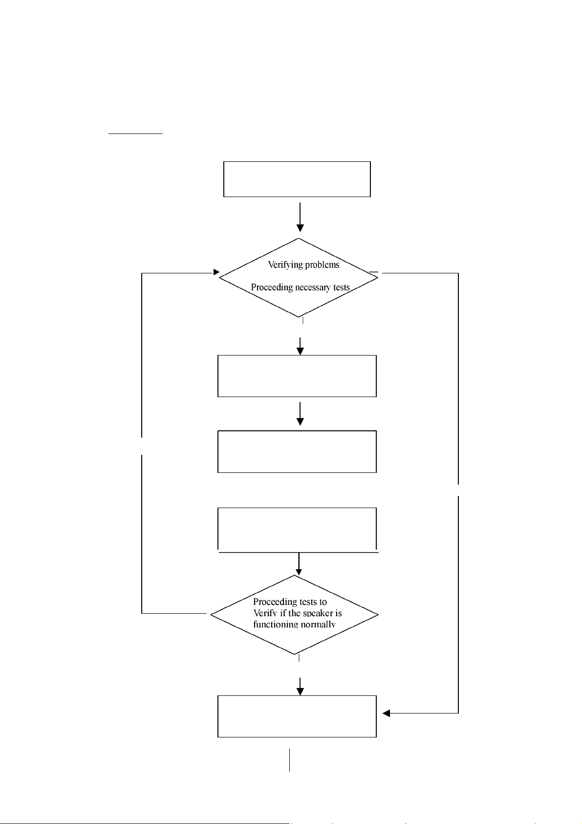
1.1 Overview
Receiving Defective speakers from
Customers
Function NG
__ __
Analyzing possible malfunction
causes
Function NG
Deciding & proceeding the
rectification methods
Replace necessary defective parts
Function OK
Return the speakers with proper
repackaging to customers
Function OK
Version : 1.0
Page 5 of 14

Service Guide
SP-i160
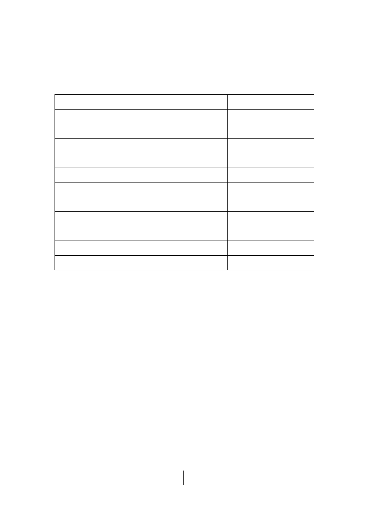
1.2 Problems
Item Problem Description
1.2.1 No sound (Line in jack no function)
1.2.2 Power LED (indicator) no light
1.2.3
Li-ION battery can’t charge
Version : 1.0
Page 6 of 14

Service Guide
Attention
SP-i160
Please follow the numbered sequence marked within parenthesis given in individual Flow
chat, in that this is the best-recommended sequence to rectify the problems.
1.2.1 One or more channels no sound (Line in jack no function)
Problem
Analyzer and
Identify the Causes
No sound
Broken or short circuit
Speaker cable
dis-connect , JACK1 or
Defective U1,
U4
JACK2 defective or
speaker damaged
Solutions
Check solder points on
PCB
Version : 1.0
Check and Replace
defective IC
Page 7 of 14
Re-connect speaker
cable or replace
defective speaker(s)

Service Guide
SP-i160
1.2.2 Power LED (indicator) no light
Power LED (indicator) no light
Problem
Analyzer and
Identify the Causes
Solutions
Power switch or LED
defective
Defective
J1
Re-solder or replace
defective component(s)
1.2.3 The Li-ION Battery can’t charge
Problem
Analyzer and
Identify the Causes
Solutions
Broken or short circuit
Check solder points on PCB
The Li-ION battery can’t
charge
U2 Battery
Check and Replace defective
components
Version : 1.0
Page 8 of 14

Service Guide
SP-i160
Chapter 2. Specifications
NO. Description
1
Out Power at THD 10%
2
Sensitivity
3
Freq. Response (1KHz -3dB) Hz
4
Separation
5
S/N ratio
6
Hum & Noise (Vol.: max)
Version : 1.0
Unit
W
mV
dB
dB
mV
Page 9 of 14
Specifications
≧≧≧≧ 1.8
600 ± 50
180~20K ± 10%
≧≧≧≧ 40
≧≧≧≧ 80
≦≦≦≦ 2

Service Guide
in
SP-i160
Chapter 3. Block Diagram
Audio
Ac
—
►
Tone
Control
Conditioner
Volume
Control
Power
Version : 1.0
—
►
i
A
Page 10 of 14
L.CH Speaker

Service Guide
SP-i160
Chapter 4. Exploded View
Version : 1.0
Page 11 of 14

Service Guide
SP-i160
Chapter 5. Part List
DESCRIPTION
Qty UNIT
No.
RS,ASM,SP-I160,HOST,BLACK 31730952100
1
RS,ASM,SP-I160,HOST,WHITE
2
Loud Speaker 1.25" 4 ohm 1~2W
3
Rubber Pad(Φ4.8 X 2.3T), SP-i160
4
PCBA, SP-i160
5
IC, JRC NJM2761
6
IC, T1 TPA2031D1
7
IC, LN,LN2054
8
BATTERY, SP-i160
9
FANNEL BAG SP-i160 1
10
S/N LABEL SP-i160
11
CARD SP-i160 / B
12
CARD SP-i160 / W
13
INNER TRAY SP-i160
14
PET BOX, SP-i160
15
Anti-fake Label ( on Gift Box )
16
Carton, SP-i160
17
1
1
3
1
1
1
1
1
2
1
1
1
1
1/50
PC
31730952101
PC
FSA510112-1402
PC 15400009100
PC
PC
Set
PC
PC
ASL507003-0026
RCI203101-0001
FBY508037-0003
PC 12290076100
PC 12061017100
12020186100
PC
12020187100
PC 12150227100
PC 12140001100
PC 12061993100
PC 12100465100
Part No.
Version : 1.0
Page 12 of 14

Service Guide
SP-i160
Chapter 6. Schematic Diagram
Pls refer to next page
Version : 1.0
Page 13 of 14

321
4
D
J1
CN4P-USB
5
L1
5V
BEAD120
1
2
3
4
C13
151
NC
Q1
C16
151
C3
100uF
R10
2K
LD1
C2
RED
104
1
CHRG
C
C21
105
2
Out1
GND
Vcc
1
C23
V+
U4
IC-NJM2761
10
224
R8
8K2
R13
8K2
GNDGND
C19
224
B
R7
3.6k
223
4
5
INT
Vref
SW7IN28OUT29GND
Sense
6
R2
1k
224
3
IN1
C20
C22
224
105
C17
C18
GND
R9
BEAD120
4
U2
LN2054
BAT
Vcc
PROG
GND
2
R11
4.7K
S1
SW-SPDT
USB ON
BAT ON
3
5
C14
NC
Vcc
R12
2K
LD2
BLUE
BT1
BATTERY
Shut_DN
R6
100K
C1
10uF
U1
TPA2031D1
B1
VDD
C1
A1
R5
C5
240k
R4
471
68k
C4
473
PVDD
IN-
IN+
ShutDNC2GND
Vo+
Vo-
GND
A2
C11
10uF
B2
C3
A3
B3
104
C9
270P
So+
S1
SPK
So-
L2
BEAD120
L3
BEAD120
C8
270P
C10
270P
Vcc
C12
R1
68k
C6
473
R3
240k
C7
471
D
C
B
A
Title
A
Number RevisionSize
A4
Date: 21-Jan-2010 Sheet of
File: E:\MODEL INFO\KYE\F4\Mr Pai.ddb Drawn By:
SP-i160
VER090820
1 2 3 4

Service Guide
SP-i160
Chapter 7. Important Notes
7.1 Packing Requirement for Sending the PCB Assembly by Post
PCB assembly is a kind of sophisticated electronic circuit board. Well
packing will be required when sending them by post.
* Some sophisticated IC components are mounted on the PCB assembly,
hence it is necessary to pack each PCB assembly with a separate static
protecting bag, in order to avoid static electricity.
* Reliable external packing is also very important when sending PCB
assembly by post, in that it would avoid unnecessarily lost or damage.
7.2 Short of Spare Parts while Repairing a Speaker System
If you are short of spare parts when you have some speaker systems waiting
to be repaired, it would be recommended to take the necessary parts form
one speaker system, so that you may have the as many speaker systems.
Version : 1.0
Page 14 of 14
 Loading...