

Page 1

NT 250 Technical and Maintenance Manual NicomUsa Inc
TABLE OF CONTENTS
CHAPTER 1
Transmitter General Description And Installation Procedures Page 2
Remote Control Feature Page 3
Programming the NT 250 Page 5
CHAPTER 2
Electrical & Mechanical Specifications Page 10
Front Panel Description Page 13
Rear Panel Description Page 14
CHAPTER 3
250 W schematics and components list Page 15
Page 1
Page 2

NT 250 Technical and Maintenance Manual NicomUsa Inc
CHAPTER 1
GENERAL DESCRIPTION
NT 250 Transmitter Exciter
INTRODUCTION
The NT 250 FM Exciter is the latest in state of the art products available from Nicom. This
Transmitter is designed with high reliability components and is intended to give many years of
trouble free continuous service. This unit incorporates many features including a switching power
supply and a PLL frequency synthesizer.
The latest SMD technology has allowed to make a more compact unit (only 3 rack spaces) and
at the same time a very light unit (only 32 lbs).
INSTALLATION
After unpacking the module, check for any mechanical damage or loose parts inside.If there is
any transportation damage, inform the supplier immediately and do not put the module into
operation.
The voltage is applicable from 100 to 240 Volts without needing any change.
Ensure that the station’s ground system connections have a ground resistance of less than 5
ohms. The equipment’s rack or cabinet must be effectively grounded.
Check that the transmitter’s main switch is off.
Connect the power cord to the AC plug.
STARTING PROCEDURE
Connect the antenna cable to the ‘N’ connector on the back of the unit. The antenna system must
be set up to operate at the transmitter’s working frequency.
ATTENTION
Antenna matching is extremely crucial for FM transmitters. Operate this unit only after verifying
good matching. Mismatching will decrease the communication distance and unduly stress the
semiconductors.
Turn on the transmitter.
After 1 or 2 seconds the green LED “PLL LOCK” should turn on. This indicates that the frequency
is locked on the programmed value.
After 1 more second the “RF ENABLE” green LED will come on. This indicates that RF power is
being delivered to the output connector on the back.
Now you can input modulation. For MONO operation connect your signal to the XLR connector
following the connecting instructions printed on the back of the transmitter and then regulate the
input level with the apposite trimmer. For stereo input, use the BNC connector labeled “MPX”.
Regulate the audio with the apposite trimmer.
Note:Be sure that the modulation level is close to but not more than 75KHz. 75KHz is 100%
modulation. Lower modulation level will decrease the S/N value while over-modulation (>100%)
will cause distortion at the receiver and it is against current regulations.
Page 2
Page 3

NT 250 Technical and Maintenance Manual NicomUsa Inc
REMOTE CONTROL FEATURE
The NT 250 is equipped with a 9 pin RS 232 connector that allows all the mains telemetry
functions. The software is supplied with the unit and with this CD rom it's possible to monitor
and to change the main parameters ot the NT 250 on the computer's screen.
The NT 250 is also supplied with the interlock connector that allows to switch the power on and
off simply by grounding the inner conductor of the BNC.
NOTE:
The CD Rom supplied contains the remote control software of the NT 250.
REMOTE CONTROL SOFTWARE
INSTALLATION
The NT 250 comes with a Serial port RS 232. This port allows a Bi-Directional remote control of
the unit from a PC.
INSTALLING THE SOFTWARE
1. Insert the NT 250 CD-ROM into the CD drive.
2. Run Setup.exe file found in the main folder of the CD-ROM. The installation will continue
automatically asking only for the name of the folder of the hard drive where the program will
be installed. It will be necessary to reboot the computer.
3. Once installed, the Tx_Nicom program icon can be recalled by clicking : Start - Programs Tx_Nicom icon.
CONNECTING THE NT 250
The NT 250 is equipped with a Serial Port (RS232) in the rear panel. To connect the computer
with the NT 250 we recommend standard serial cables Pin-to-Pin; the lenght of the cable must
stay within 60 feet.
REMEMBER TO CLOSE THE PROGRAM BEFORE REMOVING THE CONNECTING CABLE
Page 3
Page 4

NT 250 Technical and Maintenance Manual NicomUsa Inc
RUNNING THE PROGRAM
Once the program is running, from the main screen it is necessary to click the POWER ON
button; the screen will light up and a message" COMMUNICATION IN PROGRESS" will appear.
After few seconds, on the left side of the screen, the operating frequency will appear together
with all the other parameters. If not, check the Communication port setting (COM1-COM 2).
To change it, click the File menu and then select "set Port".
The other parameters shown on the screen are the following:
1.
Temperature in Celsius ( remember that Farheneit is Celsius x 1.8 + 20)
2. Lock Indicator showing that PLL circuit of the unit is locked
3. On the Air showing that the unit is transmitting
4. RF Forward giving the amount of Watts radiated
5. RF Reflected giving the amount of reflected power
On the right side of the screen there are four buttons that allow to modify the parameters:
a. Send Button to be used after a change of frequency is made
b. Set Frequency allows the change of frequency by clicking the new frequency on
the keyboard on the left side of the screen
c. Disconnect allows to disconnect the system
d. RF On turns up and down the power
Page 4
Page 5
NT 250 PROGRAMMING
Connect a 50 ohm load or 50 ohm antenna to the RF output, connect the
equipment into a mains supply (100÷240 VAC). The equipment is factory
pre-set to 50 W.
Switch ON the power and the yellow V POWER LED will light.
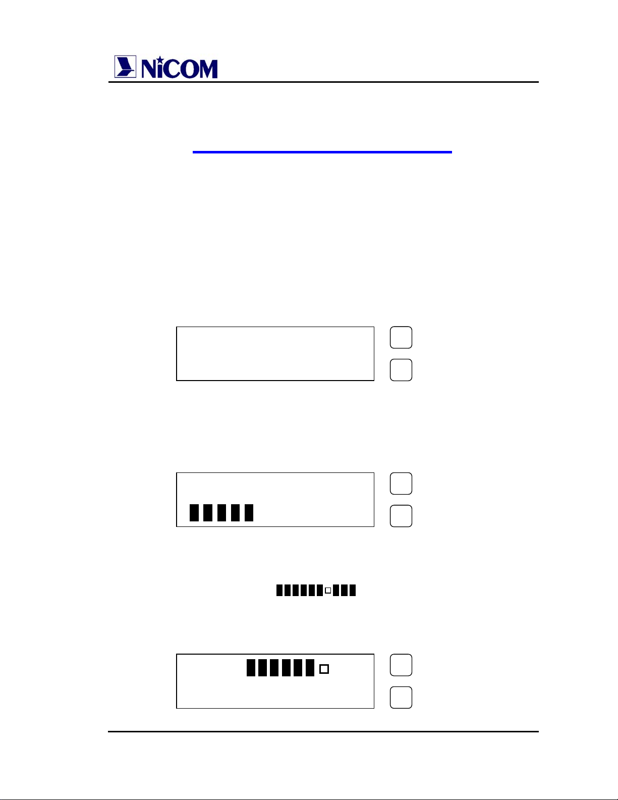
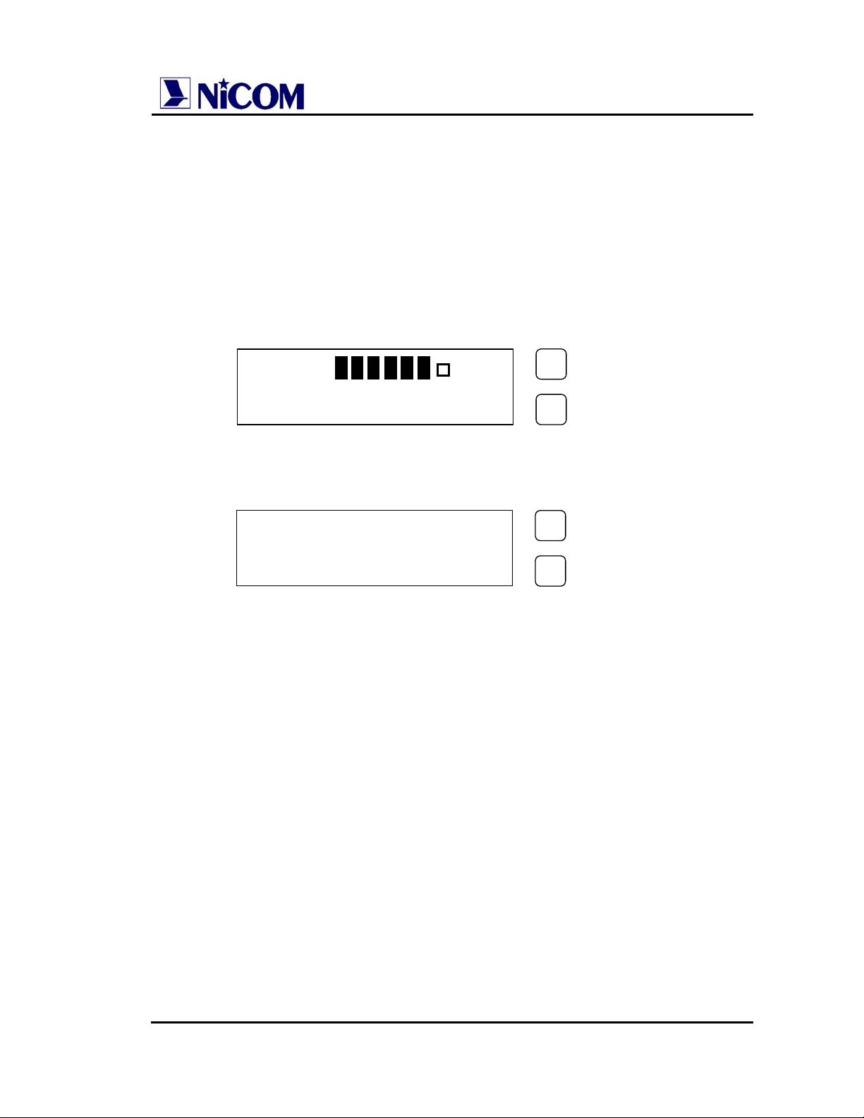
The Display will show:
After 3 seconds the green PLL LOCK led will light and the Display will
show an increasing bar. After a further 5 seconds the green ENABLE will
light and there will be output power.
At this point the Display will show the next parameter:
•
Level Modulation (MOD > );
•
Forward Power (FRW 50.0W);
• Reflected Power (RFL 0.4W).
MOD >
FRW 50W RFL 0.4W
WAIT
WAIT
PROGRAM
SETTING
PROGRAM
SETTING
PROGRAM
SETTING
Page 6
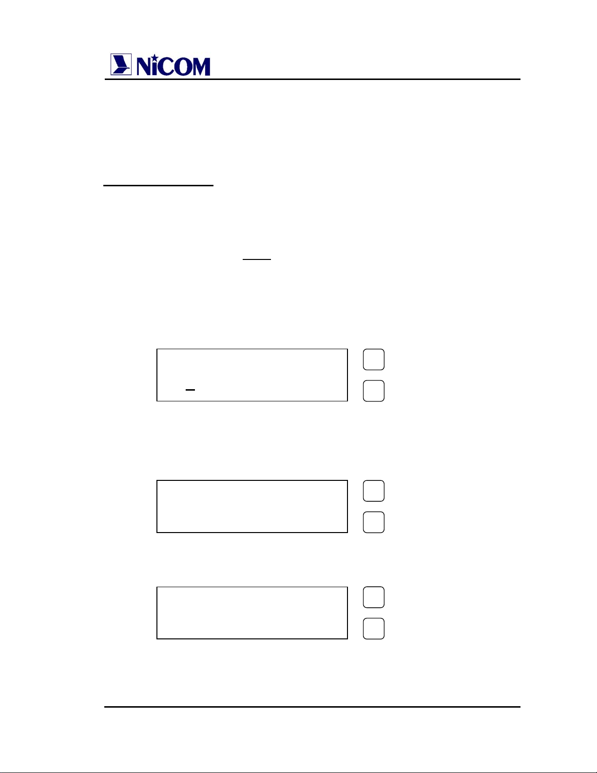
The default frequency is 98.000 MHz.
To display the frequency push the SETTING key.
In order to display the parameter push the SELECT key.
Display Password
The Password mode is factory set to enable, and is not possible change
this setting.
The default password is
The way for changing the password is the following:
• Press the PROGRAM key for 3 seconds;
• Press the PROGRAM key to move the underscore character position
at the required digit, and press the SETTING key to confirm the digit.
Repeat the same for the two remaining digits.
• If the password is correct press the SETTING key to confirm,
otherwise press the PROGRAM key to select again.
PASSWORD
PASSWORD
PASSWORD
1 2 3
.
1 2 3 4 5 6 7 8 9
0
*
0 1 2 3 4 5 6 7 8 9
*
*
*
0 1 2 3 4 5 6 7 8 9
PROGRAM
SETTING
PROGRAM
SETTING
PROGRAM
SETTING
Page 7
If the password is not correct an error is displayed:
After a few seconds the display will show the parameters again.
•
When the password is correct, the display will show:
To change the password press the SETTING key.
To change the frequency press the PROGRAM key.
•
For changing the password proceed with the same method for the
required password:
The confirmation password will be required.
CONFIRM (Y/N) ?
N=SEL. Y=SET.
ERROR
PASSWORD
NEW PASS . = SET.
NEW FREQ . = PRG
NEW PASSWORD
0
1 2 3 4 5 6 7 8 9
CONFIRMATION
1 2 3 4 5 6 7 8 9
0
PROGRAM
SETTING
PROGRAM
SETTING
PROGRAM
SETTING
PROGRAM
SETTING
PROGRAM
SETTING
Page 8
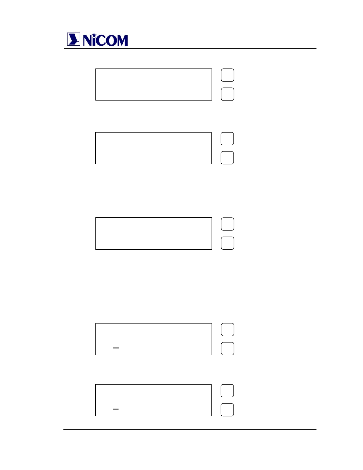
If the password is correct the display will show:
If the confirmation password is wrong the display will show:
IMPORTANT NOTE
NEW PASSWORD
STORED
ERROR
CONFIRMATION
! BE CAREFUL !
Once the password is set, it must be remembered, otherwise
neither the frequency nor the password can be reset and the unit
will have to be returned to Nicom for resetting.
Display Change of Frequency.
•
Press the PROGRAM key for 3 seconds and enter the correct
password. At this point press again the SELECT key:
•
Press the PROGRAM key to change the desired digit and press the
SETTING key to confirm it.
NEW PASS . = SET.
NEW FREQ . = PRG
FREQUENCY ?
MHz 1
03.900
PROGRAM
SETTING
PROGRAM
SETTING
PROGRAM
SETTING
PROGRAM
SETTING
Page 9
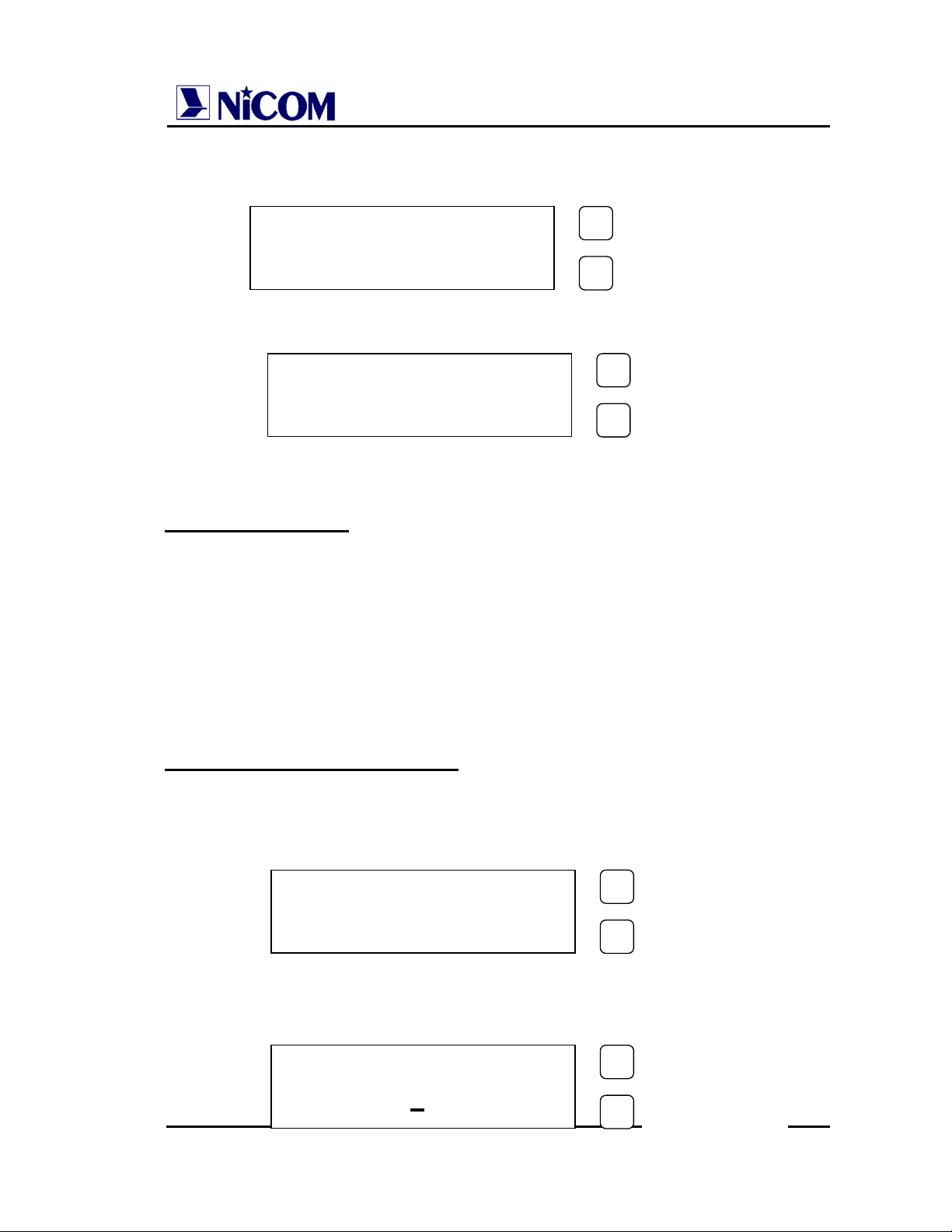
The underscore character indicates which digit can be change.
To move the underscore character hit the PROGRAM key.
When the new frequency is chosen, then press the SETTING key
confirm it.
After a “WAIT CYCLE”, the display will show the parameters:
After 7 minutes the display light will switch off and the display will show:
MOD >
FRW 50W RFL 0.4W
NICOM
MHz 103.900
PROGRAM
SETTING
PROGRAM
SETTING
Page 10

NT 250 Technical and Maintenance Manual NicomUsa Inc
CHAPTER 2
ELECTRICAL SPECIFICATIONS
NT 250 TECHNICAL DATA
Power output: 2 to 270 Watts continuously variable
Frequency of operation: Sinthesized with TXCO crystal reference
RF output connector/ Impedance: Type "N" Female / 50 Ohms
±
Frequency Stability: Better than 5ppm (
Frequency Range: 87.5 - 108 Mhz
Frequency programming: Digitally in 10 Khz increments.
Modulation type: Direct FM at the carrier frequency
S/N Ratio (ref. to 50 Khz / 1000 Hz): Mono > 70dB - Stereo > 65 dB.
Distortion, THD: < 0.1 %, Typ. 0.05 %
Asyncronous AM S/N ratio: 65 dB below reference carrier with 100% AM
modulation, 75 usec de-emphasis (no FM
modulation present).
Syncronous AM S/N ratio: 60 dB below reference carrier with 100% AM
modulation (FM modulation
DC input power: 24 V VDC 8 A
AC input power: Single phase 100 - 240 V
Ambient Temperature Range: 0° to 50° C (+32° to +122° F)
Spurious and Harmonic or
Subharmonic Emissions: < -80 dB or better
Stereo Separation 55 dB @ 1 Khz
500 Hz) , 0 to 50° C.
±
75 Khz).
Page 10
Page 11

NT 250 Technical and Maintenance Manual NicomUsa Inc
COMPOSITE OPERATION
Composite inputs four total, 1 for MPX and 3 for SCA
MPX input 1 unbalanced bnc connector
MPX input impedance 2 K ohms
MPX input level 3,5 V p-p (1,237 Vrms/3.64 dBm)
Composite FM unweighed S/N ratio > 78 dB below ± 75 Khz deviation at 400 Hz
measured in a 30 Hz - 100Khz bandwidth with
75 usec de-emphasis (RMS)
Composite Total Harmonic Distortion 0.05 % typical
Composite Intermodulation Distortion 0.05 %, measured with a 1 Khz and a 1.3 Khz
tone, 1:1 ratio, at 100% modulation
Baseband 30 Hz - 60 Khz within 0.15 dB
Crosstalk main to stereo subchannel and stereo subchannel
to main > 55 dB ( 60 dB typical)
SCA Inputs 3 unbalanced BNC connectors
SCA Input Impedance 10 K Ohms
SCA Input Levels 0 dBm (775 mV rms/ 2.2 V p-p) nominal for
±
75 Khz deviation, adjustable
±
SCA Amplitude Response
Crosstalk 67 Khz SCA to main or to stereo subchannel >65dB
0.8 dB, 40 Khz to 100 Khz
92 Khz SCA to main or to stereo subchannel >70 dB
MONOAURAL OPERATION
Audio Input Impedance 600 Ohms balanced or unbalanced; 50 dB common
mode suppression
Audio Input Level 0 dBm (775 mV rms/ 2.2 V p-p) nominal for
±
75 Khz deviation, adjustable
FM S/N Ratio
> 70 dB below ± 75 Khz deviation at 400 Hz
measured in a 30 Hz - 20Khz bandwidth with
75 usec de-emphasis (RMS)
Audio Frequency Response
Intermodulation Distortion
±
0.8 dB, 30 Hz to 15 Khz
0.05 %, measured with a 1 Khz and a 1.3 Khz
tone, 1:1 ratio, at 100% modulation
Page 11
Page 12

NT 250 Technical and Maintenance Manual NicomUsa Inc
MECHANICAL SPECIFICATIONS
Chassis Dimensions: 132 mm (5.1") H
326 mm (12.83")D
445 mm (17.51) W
Front panel dimensions: 483 mm (19") W
132 mm (5.1") H
Ambient operating temperature: from 0 to + 50 C (+32 to +122 F)
Humidity: 90% maximum, non condensing.
Weight: 32 Lbs ( 14.5 Kg)
Shipping Dimensions: 22" x 23" x 8"
Page 12
Page 13
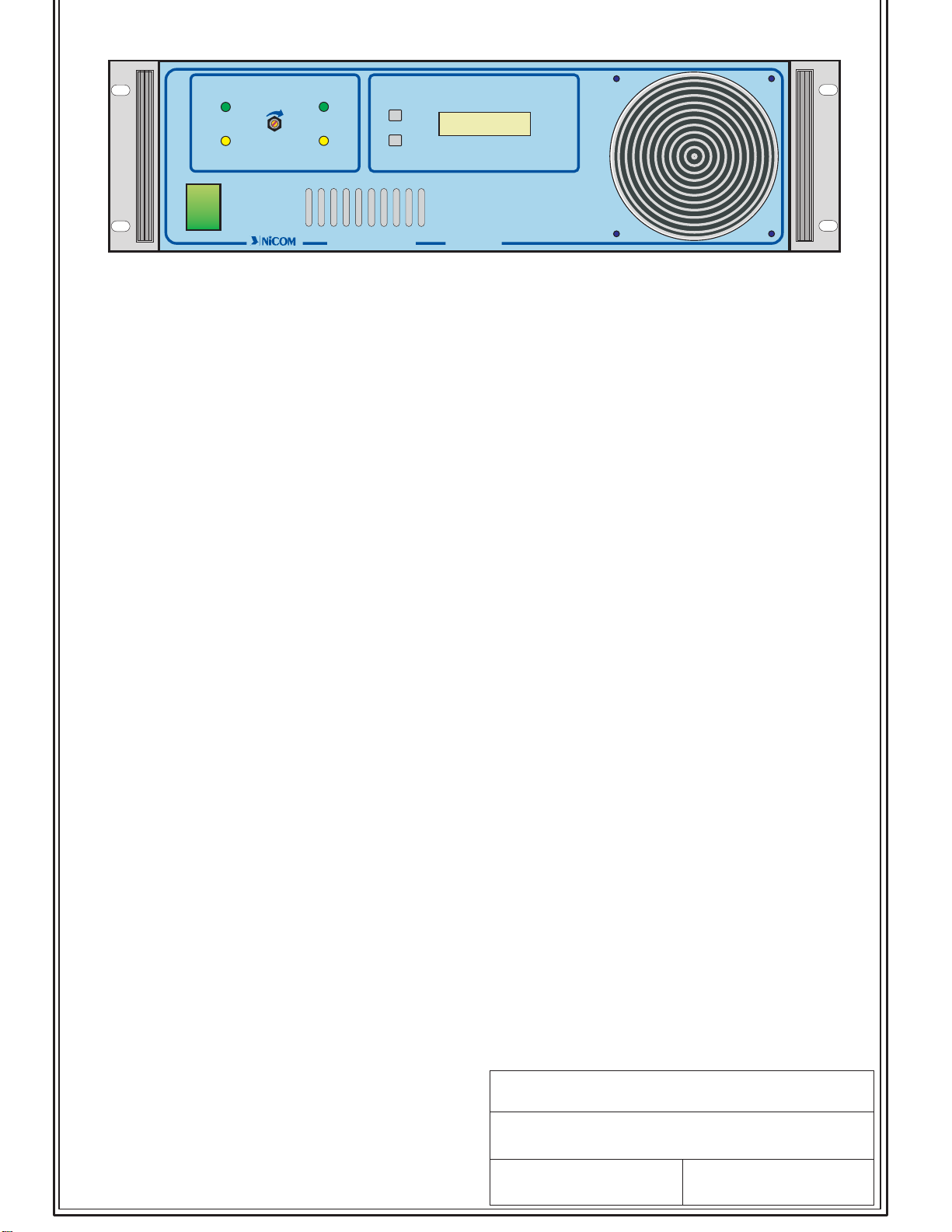
LOCK
3
PWR ADJ.PWR ADJ.
1
VDC2
ON
ENABLE
4
5
2
VDC1
PROGRAM
SET
7
6
8
9
OFF
EXTERNAL POWER SUPPLY CORRECT OPERATION YELLOW INDICATOR
1-
FM TRANSMITTERFM TRANSMITTER
NT 250NT 250
2 - POWER STAGE SUPPLY CORRECT OPERATION YELLOW INDICATOR
3 - PLL LOCK FREQUENCY CONTROL CORRECT OPERATION CIRCUIT GREEN INDICATOR
4 - PRESENCE OF RF POWER AT FREQUENCY SET ON OUTPUT CONNECTOR GREEN INDICATOR
5 - RF OUTPUT POWER ADJUSTING FROM 0 TO OVER 250W
6- LCD MULTIMETER DISPLAY SHOWING:
- operational frequency
- modulation
- forward rf power
- reflected power
7-8-THESE PUSH BUTTONS ALLOW TO TO SELECT ON LCD DISPLAY THE FOLLOWING MENU:
- display parameter
- password
- change of operational frequency
9 - MAINS SWITCH
TITLE
DATE
NICOM
NT250 FRONT PANEL
DRAWING NO.
JULY 2001
Nt250 Front Panel.CDR
Page 14
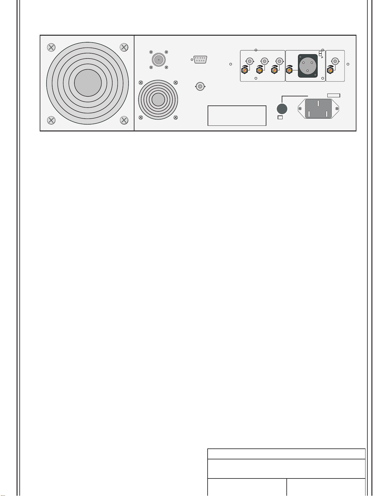
3
RF OUTPUT
50 OHM 250W
16
REMOTE CONTROL
INTERLOCK
SCA 3
6
SCA 2
7
SCA 1
8
1 GND
2
+
-
3
MONO
50
MPX
75
S
14
4
9
11
10
13
12
15
5
Voltages under equipment cover plate
can be hazardous to your life. Equipment
only can be handled by qualified personnel.
WARNING
FUSE
A
2
MAINS V
1
1 - MAIN SUPPLY CONNECTOR
2 - AC FUSE 3A
3-FAN
4 - DB 9 PIN INPUT / OUTPUT CONNECTOR FOR TELEMETRY ( opt.01 )
5 - BNC FEMALE FOR CONNECTION OF THE INTERLOCK LOOP - A CONNECTION TO GROUND INHIBIT RF POWER
6-7-8- BNC FEMALES FOR SUBCARRIERS GENERATORS INPUTS
9-10-11- SCA INPUT ADJUSTING LEVELS
12 - XLR FEMALE BALANCED MODE MONO AUDIO INPUT
13 - MONO INPUT ADJUSTING LEVEL
CE
14 - BNC FEMALE FOR THE COMPOSITE MPX INPUT
15 - MPX INPUT ADJUSTING LEVEL
16 - N FEMALE FOR RF OUTPUT POWER
TITLE
DATE
JULY 2001
NICOM
Nt250 EXCITER
REAR PANEL LAYOUT
DRAWING NO.
Nt250 Rear Panel.cdr
Page 15

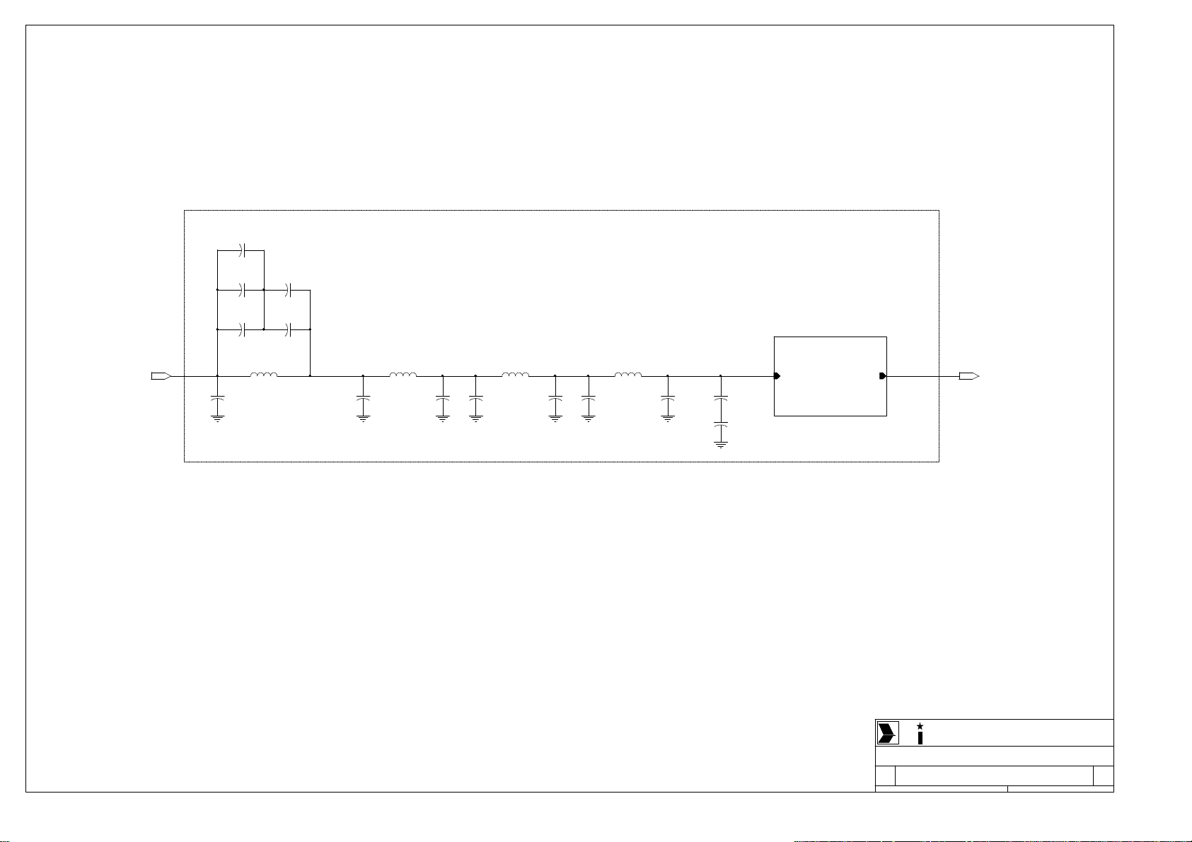
MPX
LIMITER
VCO
RF DRIVER
ADJ
RF AMPLIFIER
LPF
DIRECTIONAL
COUPLER
RF OUTPUT
MONO
SCA
AUDIO INPUT
POWER
SUPPLY
VDCVAC
TCXO
12.8
MHz
PLL
MICROCONTROLLER
SIGNAL INTERFACE
DISPLAY
NICOM
MHz 98.000
RS232
N COM
Title
FUNCTIONAL SCHEMATIC
Size Document Number Rev
B
Date: Sheet of
Mod. NT 250
1 1Friday, October 24, 2003
1.0
Page 16

RV1
275V
VAC
110V - 230V
N
L
RV2
275V
S1
AC MALE
with
EMC FILTER
F1
3.15A
15V POWER SUPPLY
L
N
GND EARTH
FAN1
24 V
1
MPX
J2
BNC
2
F2
150mA
+15V
GND
L1
CHOKE
MPX
GND MPX
+15V
GND
JR1
XLR
L2
CHOKEL3CHOKE
MONO+
MONO
C+- G
MONO-
J3
BNC
L4
CHOKE
GND SCA1
GND MONO
ESVA BOARD
SCA1
SCA1
SCA2
J4
BNC
L5
CHOKE
SCA2
GND SCA2
SCA3
J5
BNC
L6
CHOKE
SCA3
GND SCA3
DJ3-RS232
RF OUTPUT
INTERLOCK
J6
BNC
L7
CHOKE
Interlock
GND Interlock
GND
TX
RX
RS232
5
9
4
8
P1
3
DB9 MALE
7
2
6
1
J1
RF OUTPUT
RF FILTER
RF OUTPUT
RF FORWARD
RF REFLECTED
GND
COAX1
RG303
FAN2
12 V
1
2
RF AMPLIFIER 250W
SW1
SW 2DEV
COAX2
RG316
FORWARD POWER
V- GATE
TEMPERATURE
REFLECTED POWER
FAN3
12 V
1
2
R1
F3
3.9 / 5W
POWER SUPPLY
L
N
GND EARTH
L
N
1
3
GND
+48V
CONTROL PANEL
150mA
J4-LED & ADJ POWER
DISPLAY
F4
1A
R2
3.9 / 5W
DISPLAY
RF INPUT
RF OUTPUT
RF INPUT
GND
+27V
GATES
TEMPERATURE
-12V
NICOM
2
4
L
N
LED & ADJ POWER
DISPALY
MHz 98.000
N COM
Title
GENERAL SCHEMATIC
Size Document Number Rev
A3
Date: Sheet of
Mod. NT 250
1 8Friday, October 24, 2003
1.0
Page 17

TERM4
FUSE A
TERM5
FUSE B
L IN
GND HEART
N IN
TERM1
TERM2
TERM3
C2
1uF / 350V
L8
0.8mH
L9
0.8mH
C1
2.2nF / 350V
C3
2.2nF / 350V
RV1
275V
RV3
275V
RV2
275V
TERM6
L OUT
SW1
TERM7
N OUT
N COM
Title
Size Document Number Rev
Date: Sheet of
A
EMC FILTER
Mod. EMC-03
1 1Friday, January 31, 2003
1.0
Page 18

Page 19

+24V
+24V
+5V
+15V
VADJ
ADJ-A
ADJ-B
ADJ-C
DATA
CLOCK
+5V
GND
SW1
SW2
+24V
+5V
GND
-15V
+15V
+5V
GND
+15V
-15V
V-ADJ
IN FWD PW
IN RFL PW
V-GATE
LED RF
ADJ-A
ADJ-B
ADJ-C
INTERLOCK
FWD PW
RFL PW
DB9_FWD
DB9_RFL
+5V
+15V
GND
LED LOCK
LOCK
DATA
CLOCK
ENABLE
GND
+5V
FWD PW V-ADJ
RFL PW
VU METER
TEMP.
DATA
CLOCK
ENABLE
INTERLOCK
LOCK
SW1
SW2
TEMP.
IN FWD PW
IN RFL PW
V-GATE
+15V
V-ADJ
+15V
GNDGND
+15V
GND
GND
J2
SMB
V-ADJ
+15V
DRIVER OFF
V-VCO
RF IN
GND RF IN
Protection & Meter
PLL
FORWARD POWER
REFLECT POWER
V. GATE
LED RF
Interlock
RF FWD METER
RF RFL METER
DB9_FWD_PW
DB9_RFL_PW
LED LOCK
PLL LOCK
ENABLE
GND DATA
Microcontroller
Forward PW
Reflected PW
VU Meter
Temperature
DATA
CLOCK
ENABLE
RF ON/OFF
PLL LOCK
Power Supply
+15V
VA
J1
POWER
J4
BNC
J8
BNC
J9
BNC
J10
BNC
J11
XLR
2 1
J6
BNC
J12
DB9_AUX
TX
GND
RX
J13
DB9
1
+24V
GND
D1
LL4148
1
2
INTERLOCK
+24V
GND
Audio
1
2
1
2
1
2
3 4
1
2
3
2
1
SW1
DB9 MONITOR
1
2
3
4
10
SCA 1
GND SCA 1
SCA 2
GND SCA 2
SCA 3
GND SCA 3
GND MONO
MONO -
MONO +
MPX
GND MPX
R4 10K
8
7
6
5
L8 22uH
C18
1nF
D2 LL4148
L10 22uH
C22
1nF
L11 22uH
C24
1nF
VB
+5V
-5V
VC
VD
-15V
VU METER
BF OUT
GND BF OUT
+5V
C19
1nF
INTERLOCK
DB9_FWD
C23
1nF
DB9_RFL
C25
1nF
+15V
VA
VB
+5V
-5V
VC
VD
-15V
+15V
+15V
VA
VA
VB
VB
GND
GND
VC
VC
VD
VD
-15V
-15V
RF Driver
RF OUTPUT
GND RF OUTPUT
DRIVER OFF
RF INPUT
GND RF INPUT
VCO
RF OUT
GND RF OUT
V-VCO
VU METER
L7
22uH
C16
39pF
L9
22uH
C20
39pF
BF IN
GND BF IN
C17
39pF
C21
39pF
RX RS232
TX RS232
RF PLL
GND RF PLL
R1
1K
+24V
ADJ-A
ADJ-B
ADJ-C
LED LOCK
LED RF
SW1
SW2
+5V
-5V
GND
+5V
+5V
-5V
Title
Size Document Number Rev
C
Date: Sheet of
LED PW
J19
PUSH
SW2
1
GND
2
SW1
3
C1
+
22MF / 16V
R2
2K2
C3
1nF
L2
22uH
C5
1nF
L3
22uH
C7
1nF
L4
22uH
C9
1nF
L5
22uH
C11
1nF
L6
22uH
C13
1nF
N COM
Mather Board ESVA-1C
ADJ-A
1
ADJ-B
2
ADJ-C
3
GND
4
LED RF
5
GND
6
LED LOCK
7
LED PW
8
ADJ-A
1
ADJ-B
ADJ-C
GND
SW2
+
L1
22uH
C4
1nF
C6
1nF
C8
1nF
C10
1nF
C12
1nF
C14
1nF
C15
+
2.2MF / 50V
Mod. ESVA-1C
DJ2x5
J3
C2
22MF / 16V
J20
RJ45
LED PW
LED LOCK
LED RF
GND
SW1
10
TERM1
TERM2
TERM3
TERM4
TERM5
TERM6
TERM7
1 1Friday, October 24, 2003
J5
STEREO_CODER
3
2
1
1
J7
DJ3
R3
10K
+5V
-5V
FWD PWR
RFL PWR
V. GATE
V-ADJ
GND
1.0
Page 20

BF OUT
GND BF OUT
MODULATION
R6
47K
LIMITER
D3
BAT43
J14
DJ3
D4
BAT43
C31
1000MF / 35V
R17
3K9
R19
3K9
R16
200
+
R9
5K
R15
1K2
+15V -15V
R18
1K2
U1B
OP275
STEREO
C26
VA
R5
84
27K
5
+
7
6
-
VB
R11
47K
C28
22pF
60pF
R8
47K
U1A
OP275
R13
10K
1
R7
12K
3
+
2
-
R10
27K
C29
C27
10pF
R14
12K
R21
12K
470pF
C32
470pF
R12
1K
R20
1K
SCA 1
GND SCA 1
SCA 2
GND SCA 2
VU METER
MONO +
GND MONO
MONO -
C30
+
+15V
R24
33+C34
10MF / 35V
D5
U2A
LM358
R37
4K7
R42
10K
R47
4K7
84
3
+
1
2
C38
10MF / 35V
+
R33
33
-15V
C39
10pF
R35
560K
J15
DJ3
VC
R38
100
U3A
84
LF353
3
+
1
2
-
VD
R51
4K7
C45
47pF
CMRR
R52
10K
50uS
75uS
R44
10K
C40
4.7nF
C42
6.8nF
R31
100K
R46
3K9
12345
8
LL4148
R30
D6
3V3
R39
10K
R48
10K
C37
+
560K
2.2MF / 50V
C41
100MF / 25V
+
R40
R41
1K2
1K2
C43
100MF / 25V
+
D7
LL4148
R25
220K
U2B
LM358
5
+
7
6
D8
LL4148
R32
100K
6
FILT1
FILTER 19KHz
7
-
R36
10K
R45
3K9
5
+
6
-
R49
2K2
100MF / 16V
R179
20K
R26
100K
U3B
LF353
7
R50
10K
MONO
C44
47pF
R43
10K
R23
12K
R28
4K7
C35
470MF / 35V
+
R34
NC
C33
470pF
C36
470MF / 35V
R29
10K
R22
1K
+
R27
1K
+15V
VA
VC
VB
VD
-15V
SCA 3
GND SCA 3
MPX
GND MPX
+15V
VA
VC
GND
VB
VD
-15V
N COM
Title
Audio Output
Size Document Number Rev
C
Date: Sheet of
Mod. ESVA-1C
1 1Friday, October 24, 2003
1.0
Page 21

+5V
GND
VU Meter
Forward PW
Reflected PW
Temperature
TX RS232
RX RS232
DATA
CLOCK
ENABLE
RF ON/OFF
PLL LOCK
SW1
SW2
+5V
CH0
CH1
CH2
CH3
TX
RX
JP1
R55 10K
R56 10K
R57 10K
R58 10K
C56 1MF / 16V
C58 1MF / 16V
+
+
D9 LL4148
R60 NC
R59 NC
R62 10K
R61 NC
+
R63 1K5 R54 1K
C51 100MF / 25V
C54
+
1MF / 16V
U7 MAX232
1
C1+
3
C1-
4
C2+
5 6
C2- V-
7
T2 OUT
8
R2 IN
14
13 12
15
PLL_DTA
PLL_CLK
PLL_EN
RF_ONOFF
PLL_LOCK
R2 OUT
T1 OUT
R1 IN R1 OUT
GND
SW1
SW2
VCC
V+
T2 IN
T1 IN
C46
10MF / 35V
16
2
10
9
11
3
4
5
6
1
9
8
7
C55
0.1MF
+5V
+
U4 ADC0834
CH0
CH1
CH2
CH3
Vref OUT
Vref IN
AGND
DGND
+5V
C57 1MF / 16V
C59 1MF / 16V
LCD1 DISPLAY V20350
D1
D2
D3
PROG.
+5V
12
R53
10K
3456789
D7
D5
D4
J16
DJ2
C53
0.1MF
D[0:7]
D0
D1
D2
D3
D4
D6
D7
DB0
DB1
DB2
_DB0
_DB1
_DB2
78910111213
24252627282930
D1D5D0D6D2
R66 6k8
R67 6k8
+5V
R72 6k8
R70 6k8
R69 6k8
R68 6k8
R71 6k8
J17
DJ2
DB3
_DB3
D3
D4
SCLK
SDTA
PLL_CLK
PLL_DTA
SW2
SW1
SETUP
DB4
_DB4
D5
DB5
_DB5
D6
DB6
_DB6
LAMP
14
D7
DB7
31
_DB7
456
RS
RSRWEN
_RS
_RW
212223
EN
RW
R65
1K2
_EN
GND
VCC
V0
3
LED -
LED +
NC
_GND
_VCC
_V0
20
_LED-
_LED+
_NC
1
2
151617
18
19
323334
+5V
C52
R64
10K
Q1
BC327
0.1MF
Y1
11.0592MHz
+5V
VCC
P0.0
P0.1
P0.2
P0.3
P0.4
P0.5
P0.6
P0.7
P2.0
P2.1
P2.2
P2.3
P2.4
P2.5
P2.6
P2.7
ALE
PSEN
B
CA
D
+
C
D0
C50
22MF / 16V
44
43
42
41
40
39
38
37
36
24
25
26
27
28
29
30
31
33
32
12
231
34
C47
0.1MF
14
VCC
10
DO
CLK
SARS
+
+
SDTA
13
DI
SCLK
12
ADC_EN
2
CS
11
TXD
C48
33pF
C49
33pF
EN
RW
RS
LAMP
SETUP
RXD
TXD
SW1RXD
SW2
PLL_EN
ADC_EN
RF_ONOFF
PLL_LOCK
2
35
10
21
20
2
3
4
5
6
7
8
9
11
13
14
15
16
17
18
19
22
U5
MAX810L
VCC
RST
GND
EA
RST
XTAL1
XTAL2
P1.0
P1.1
P1.2
P1.3
P1.4
P1.5
P1.6
P1.7
RxD
TxD
INT0
INT1
T0
T1
WR
RT
GND
3
1
U6 T89C51RD2
N COM
Title
Microcontroller
Size Document Number Rev
B
Date: Sheet of
Mod. ESVA-1C
1 1Friday, October 24, 2003
1.0
Page 22

+24V
GND
C60
1000MF / 35V
+15V
D10
LED
R73
1K2
+5V
D11
LED
R74
390
VA
VC
-5V
D14
LED
C62
+
1000MF / 25V
C79
1000MF / 25V
+
L13
22uH
L15
22uH
+
C63
100MF / 25V
C80
100MF / 25V
+
+
C64
47MF / 16V
C81
47MF / 16V
+
C68
0.1MF
C82
0.1MF
U9 UA7805
1
IN
R75
33
C71
0.1MF
R76
33
C74
0.1MF
2
OUT
GND
2
U11 UA7905
IN
GND
1
OUT
3
C83
0.1MF
+
C65
47MF / 16V
C72
0.1MF
C75
0.1MF
C84
47MF / 16V
+
C69
0.1MF
C70
+
22MF / 16V
C73
+
22MF / 16V
3
L12
D12
N.C.
N.C.
L14
150uHU10
MBRS340
C78
0.1MF
C67
0.1MF
U8
N.C.
1 2
V IN OUTPUT
4
FB
5
GND
ON/OFF
3
LM2575/S15
1 2
V IN OUTPUT
4
FB
5
ON/OFF
GND
3
C77
0.1MF
C61
+
100MF / 35V
C76
+
100MF / 35V D13
+
C66
0.1MF
R77
390
R78
33
C85
0.1MF
R79
33
C88
0.1MF
D15
LED
R80
1K2
C86
22MF / 16V
+
C89
22MF / 16V
+
N COM
Title
Power Supply
Size Document Number Rev
A3
Date: Sheet of
C87
0.1MF
C90
0.1MF
Mod. ESVA-1C
VB
VD
-15V
1.0
1 1Friday, October 24, 2003
Page 23

+24V
+15V
+5V
GND
-15V
Interlock
REFLECT POWER
FORWARD POWER
+24V
+15V
+5V
-15V
D33
LL4148
R103
5K
SWR PWR
R183
4K7
D34
LL4148
R184
4K7
R180
5K
+5V
R83
100K
R85
47K
+5V
C159
0.1MF
R112
12K
R114
8K2
+15V
C91
10MF / 35V
+
R81
47K
R86
47K
R101
3K3
R181
1K
+
84
3
+
2
-
C92
0.1MF
C98
2.2MF / 50V
U12A
LM358
1
D16
5V1
U12B
LM358
5
+
7
6
-
R182
470K
C160
1nF
R104
12K
R84
47K
D18
LL4148
D19
15V R100
R106
1K2
RFL
+5V
C102
10MF / 35V
+
U13A
84
LM358
3
+
1
2
-
FWD
R117
12K
R115
50K
C105
0.1MF
R113
10K
+24V
R82
47K
Q2
BC327 R87
+
D17
LL4148
R96
12K
R98
560
R105
10K
C104
10MF / 35V
C93
470MF / 35V
-15V
-15V
+15V
+
84
3
+
2
-
R89
150
R97
47K
+
-15V
R99
100
C99
10MF / 35V
U14A
LM358
1
R92
4K7
Q5
BC337
+
C100
2.2MF / 50V
+
R116
100
C94
470MF / 35V
R93
47K
R111
10K
R95
47K
C95
0.1MF
R110
12K
+
27K
5
6
C103
2.2MF / 50V
R88
150
+5V
R94
47K
Q4
BC327
Q7
BC337
R102
100K
-15V
-15V
U13B
LM358
+
7
-
R107
50K
C101
0.1MF
R91
10
Q3
BC337
2K2
R90
33
+24V
Q6
TIP41
C96
+
2.2MF / 50V
U14B
LM358
5
+
6
-
R109
10K
R108
100
7
+
C97
2.2MF / 50V
LED RF
ADJ-A
ADJ-B
ADJ-C
DRIVER OFF
VADJ
V. GATE
RF RFL METER
DB9_RFL_PW
RF FWD METER
DB9_FWD_PW
Rext 2
5K RF ADJ.
R119
10K
R118
10K
N COM
Title
Protection & Meter
Size Document Number Rev
C
Date: Sheet of
Mod. ESVA-1C
1 1Friday, October 24, 2003
1.0
Page 24

+15V
GND
R120
22
R122
22
C106
+
1000MF / 16V
C107
+
2.2MF / 50V
U15 UA7808
1
IN
2
GND
OUT
R121 47
3
C108
+
2.2MF / 50V
R123 47
C110
0.1MF
C109
+
1000MF / 16V
R124
82
R125
82
C112
0.1MF
COAX1
RG178
D20
MV209
D24
MV209
V-VCO
C118
+
2.2MF / 50V
R131
6K8
C121
47MF / 16V R132
BF IN
GND BF IN RF PLL
R133
470K
+
47K
L19
22µH
D21
MV209
D25
MV209
D22
MV209
D26
MV209
+
D23
MV209
D27
MV209
C111
10MF / 35V
C116
100pF
R128
330
L17
22µH
Q8
J310
Q9
J310
R130
470
C113
0.1MF
C117
3.3pF
C119
3.3pF
R126
680
L16
U16
4
ERA6
1
3
2
2.2µH
R129
10
C120
100pF
L18
8T/0.6D
Title
Size Document Number Rev
B
Date: Sheet of
R127
680
C114
+
10MF / 35V
C122
100pF
R134
180
C123
22pF
N COM
VCO
Mod. ESVA-1C
C115
0.1MF
GND RF OUT
RF OUT
GND RF PLL
1 1Friday, October 24, 2003
1.0
Page 25

+5V
GND
+15V
V-VCO
RF IN
GND RF IN
CLOCK
DATA
ENABLE
GND DATA
LED LOCK
PLL LOCK
+
C130
2.2MF / 50V
R151
47K
R155
470
D31
5V1
+
R152
47K
R144
1K
R161
1K
D28
LL4148
R141
10K
C134
470MF / 16V
R149
100
R159
560
C138
1nF
R135
56K
R138
18K
R145
120K
+
C131
100MF / 35V
R142
100
220MF / 25V
Q11
BC327
C135
C128
22MF / 16V
U18A
LM358
R157
470
1
7 8
R147
3K9
C136
47MF / 16V
TCXO1
MHz 12.800
N.C
GND OUT
14
Vcc
C129
1nF
U17
LMX1501
1
OSCin
2
OSCout
3
Vp
4
C133
0.1MF
+
N COM
Title
PLL
Size Document Number Rev
B
Date: Sheet of
Vcc
5
Do
6
GND
7
LD
8 9
Fin Clock
Mod. ESVA-1C
Data
16
ØR
15
ØP
14
Fp
Fr
FC
LE
J18
TEST Fref.
13
12
11
10
1 1Friday, October 24, 2003
1.0
+
+
C139
22MF / 16V
+
C140
2.2MF / 50V
C124
10MF / 35V
C126
0.1MF
Q10
R137
100
+
84
3
+
1
+
D29
LED
2
-
+
C137
0.47MF / 50V
R148
2K2
R154
47K
R150
47K
D30
LL4148
R143
560
U18B
LM358
7
R160 220K
BC327
R139
330
R146
3K9
5
+
6
-
R136
10K
R140
4K7
R153
47K
R156
47K
R158
100K
+
C125
22MF / 16V
+
C127
0.1MF
C132
22MF / 16V
Page 26

ADJ-POWER
+15V
GND
DRIVER OFF
RF INPUT
GND RF INPUT
C153
0.1MF
D32
LL4148
C146
0.1MF
R170
330
R177
12K
C158
22pF
R171
330
Q13
BFR96
C144
+
10MF / 35V
C151
R178
1nF L23
56
C154
39pF
C155
NC
R175
470
2T/.6D
R166
18K
C156
NC
R165
10K
R162
22K
C157
22pF
L24
3T/.6D
C143
0.1MF
C145
1nF
C152
220pF
R167
470
R173
39
L20
18T/0.4D
Q12
PD55003
R168
390
R163
10
R169 12
R172 10
R174 10
R176 12
C141
0.1MF
R164
10
C142
+
10MF / 35V
C147
4.7nF
L21
3T/.6D
C148
33pF
C149
NC
L22
3T/.6D
C150
10pF
RF OUTPUT
GND RF OUTPUT
N COM
Title
RF Driver
Size Document Number Rev
B
Date: Sheet of
Mod. ESVA-1C
1 1Friday, October 24, 2003
1.0
Page 27

NICOM
Rif. Value Remarks Description Code
C103 2.2MF / 50V SMD Aluminium Electrolytic Capacitor
C104 10MF / 35V SMD Aluminium Electrolytic Capacitor
C105 0.1MF SMD Multilayer Ceramic Capacitor
C106 1000MF / 16V Aluminium Electrolytic Capacitor
C107 2.2MF / 50V SMD Aluminium Electrolytic Capacitor
C108 2.2MF / 50V SMD Aluminium Electrolytic Capacitor
C109 1000MF / 16V Aluminium Electrolytic Capacitor
C110 0.1MF SMD Multilayer Ceramic Capacitor
C111 10MF / 35V SMD Aluminium Electrolytic Capacitor
C112 0.1MF SMD Multilayer Ceramic Capacitor
C113 0.1MF SMD Multilayer Ceramic Capacitor
C114 10MF / 35V SMD Aluminium Electrolytic Capacitor
C115 0.1MF SMD Multilayer Ceramic Capacitor
C116 100pF SMD Multilayer Ceramic Capacitor
C117 3.3pF SMD Multilayer Ceramic Capacitor
C118 2.2MF / 50V SMD Aluminium Electrolytic Capacitor
C119 3.3pF SMD Multilayer Ceramic Capacitor
C120 100pF SMD Multilayer Ceramic Capacitor
C121 47MF / 16V SMD Aluminium Electrolytic Capacitor
C122 100pF SMD Multilayer Ceramic Capacitor
C123 22pF SMD Multilayer Ceramic Capacitor
C124 10MF / 35V SMD Multilayer Ceramic Capacitor
C125 22MF / 16V SMD Aluminium Electrolytic Capacitor
C126 0.1MF SMD Multilayer Ceramic Capacitor
C127 0.1MF SMD Multilayer Ceramic Capacitor
C128 22MF / 16V SMD Aluminium Electrolytic Capacitor
C129 1nF SMD Multilayer Ceramic Capacitor
C130 2.2MF / 50V SMD Aluminium Electrolytic Capacitor
C131 100MF / 35V Aluminium Electrolytic Capacitor
C132 22MF / 16V SMD Aluminium Electrolytic Capacitor
C133 0.1MF SMD Multilayer Ceramic Capacitor
C134 470MF / 16V Aluminium Electrolytic Capacitor
C135 220MF / 25V Aluminium Electrolytic Capacitor
C136 47MF / 16V SMD Aluminium Electrolytic Capacitor
C137 0.47MF / 50V SMD Aluminium Electrolytic Capacitor
C138 1nF SMD Multilayer Ceramic Capacitor
C139 22MF / 16V SMD Aluminium Electrolytic Capacitor
C140 2.2MF / 50V SMD Aluminium Electrolytic Capacitor
C141 0.1MF SMD Multilayer Ceramic Capacitor
C142 10MF / 35V SMD Aluminium Electrolytic Capacitor
C143 0.1MF SMD Multilayer Ceramic Capacitor
C144 10MF / 35V SMD Aluminium Electrolytic Capacitor
C145 1nF SMD Multilayer Ceramic Capacitor
C146 0.1MF SMD Multilayer Ceramic Capacitor
C147 4.7nF SMD Multilayer Ceramic Capacitor
C148 33pF SMD Multilayer Ceramic Capacitor
C149 NC
C150 10pF SMD Multilayer Ceramic Capacitor
C151 1nF SMD Multilayer Ceramic Capacitor
C152 220pF SMD Multilayer Ceramic Capacitor
C153 0.1MF SMD Multilayer Ceramic Capacitor
C154 39pF SMD Multilayer Ceramic Capacitor
C155 NC
Page 28

NICOM
Rif. Value Remarks Description Code
C156 NC
C157 22pF SMD Multilayer Ceramic Capacitor
C158 22pF SMD Multilayer Ceramic Capacitor
C159 0.1MF SMD Multilayer Ceramic Capacitor
C160 1nF SMD Multilayer Ceramic Capacitor
L1 22uH SMD Inductor
L2 22uH SMD Inductor
L3 22uH SMD Inductor
L4 22uH SMD Inductor
L5 22uH SMD Inductor
L6 22uH SMD Inductor
L7 22uH SMD Inductor
L8 22uH SMD Inductor
L9 22uH SMD Inductor
L10 22uH SMD Inductor
L11 22uH SMD Inductor
L12 N.C.
L13 22uH Suppression Choke
L14 150uH Toroidal Inductor
L15 22uH Suppression Choke
L16 2.2µH SMD Inductor
L17 22µH SMD Inductor
L18 8T/0.6D Enamelled Copper Wire
L19 22µH SMD Inductor
L20 18T/0.4D Enamelled Copper Wire
L21 3T/.6D Tinned Copper Wire
L22 3T/.6D Tinned Copper Wire
L23 2T/.6D Enamelled Copper Wire
L24 3T/.6D Tinned Copper Wire
R1 1K 1/4W SMD Thick Film Resistor
R2 2K2 1/4W SMD Thick Film Resistor
R3 10K 1/4W SMD Cermet Skeleton Trimmer Resistor
R4 10K 1/4W SMD Thick Film Resistor
R5 27K 1/4W SMD Thick Film Resistor
R6 47K 1/4W SMD Thick Film Resistor
R7 12K 1/4W SMD Thick Film Resistor
R8 47K 1/4W SMD Thick Film Resistor
R9 5K 1/4W SMD Thick Film Resistor
R10 27K 1/4W SMD Thick Film Resistor
R11 47K 1/4W SMD Thick Film Resistor
R12 1K 1/4W Multi Turn Cermet Trimmer Resistor Panel Mount
R13 10K 1/4W SMD Thick Film Resistor
R14 12K 1/4W SMD Thick Film Resistor
R15 1K2 1/4W SMD Thick Film Resistor
R16 200 1/4W SMD Cermet Skeleton Trimmer Resistor
R17 3K9 1/4W SMD Thick Film Resistor
R18 1K2 1/4W SMD Thick Film Resistor
R19 3K9 1/4W SMD Thick Film Resistor
R20 1K 1/4W Multi Turn Cermet Trimmer Resistor Panel Mount
R21 12K 1/4W SMD Thick Film Resistor
R22 1K 1/4W Multi Turn Cermet Trimmer Resistor Panel Mount
Page 29

NICOM
Rif. Value Remarks Description Code
R23 12K 1/4W SMD Thick Film Resistor
R24 33 1/4W SMD Thick Film Resistor
R25 220K 1/4W SMD Thick Film Resistor
R26 100K 1/4W SMD Thick Film Resistor
R27 1K 1/4W Multi Turn Cermet Trimmer Resistor Panel Mount
R28 4K7 1/4W SMD Thick Film Resistor
R29 10K 1/4W SMD Thick Film Resistor
R30 560K 1/4W SMD Thick Film Resistor
R31 100K 1/4W SMD Thick Film Resistor
R32 100K 1/4W SMD Thick Film Resistor
R33 33 1/4W SMD Thick Film Resistor
R34 NC 1/4W SMD Thick Film Resistor
R35 560K 1/4W SMD Thick Film Resistor
R36 10K 1/4W SMD Thick Film Resistor
R37 4K7 1/4W SMD Thick Film Resistor
R38 100 1/4W SMD Thick Film Resistor
R39 10K 1/4W SMD Thick Film Resistor
R40 1K2 1/4W SMD Thick Film Resistor
R41 1K2 1/4W SMD Thick Film Resistor
R42 10K 1/4W SMD Thick Film Resistor
R43 10K 1/4W SMD Thick Film Resistor
R44 10K 1/4W SMD Thick Film Resistor
R45 3K9 1/4W SMD Thick Film Resistor
R46 3K9 1/4W SMD Thick Film Resistor
R47 4K7 1/4W SMD Thick Film Resistor
R48 10K 1/4W SMD Thick Film Resistor
R49 2K2 1/4W SMD Thick Film Resistor
R50 10K 1/4W Multi Turn Cermet Trimmer Resistor Panel Mount
R51 4K7 1/4W SMD Thick Film Resistor
R52 10K 1/4W Multi Turn Cermet Trimmer Resistor
R53 10K 1/4W SMD Thick Film Resistor
R54 1K 1/4W SMD Thick Film Resistor
R55 10K 1/4W SMD Thick Film Resistor
R56 10K 1/4W SMD Thick Film Resistor
R57 10K 1/4W SMD Thick Film Resistor
R58 10K 1/4W SMD Thick Film Resistor
R59 NC
R60 NC
R61 NC
R62 10K 1/4W SMD Thick Film Resistor
R63 1K5 1/4W SMD Thick Film Resistor
R64 10K 1/4W SMD Cermet Skeleton Trimmer Resistor
R65 1K2 1/4W SMD Thick Film Resistor
R66 6k8 1/4W SMD Thick Film Resistor
R67 6k8 1/4W SMD Thick Film Resistor
R68 6k8 1/4W SMD Thick Film Resistor
R69 6k8 1/4W SMD Thick Film Resistor
R70 6k8 1/4W SMD Thick Film Resistor
R71 6k8 1/4W SMD Thick Film Resistor
R72 6k8 1/4W SMD Thick Film Resistor
R73 1K2 1/4W SMD Thick Film Resistor
R74 390 1/4W SMD Thick Film Resistor
R75 33 1/4W SMD Thick Film Resistor
Page 30

NICOM
Rif. Value Remarks Description Code
R76 33 1/4W SMD Thick Film Resistor
R77 390 1/4W SMD Thick Film Resistor
R78 33 1/4W SMD Thick Film Resistor
R79 33 1/4W SMD Thick Film Resistor
R80 1K2 1/4W SMD Thick Film Resistor
R81 47K 1/4W SMD Thick Film Resistor
R82 47K 1/4W SMD Thick Film Resistor
R83 100K 1/4W SMD Thick Film Resistor
R84 47K 1/4W SMD Thick Film Resistor
R85 47K 1/4W SMD Thick Film Resistor
R86 47K 1/4W SMD Thick Film Resistor
R87 2K2 1/4W SMD Thick Film Resistor
R88 150 1/4W SMD Thick Film Resistor
R89 150 1/4W SMD Thick Film Resistor
R90 33 1/4W SMD Thick Film Resistor
R91 10 1/4W SMD Thick Film Resistor
R92 4K7 1/4W SMD Thick Film Resistor
R93 47K 1/4W SMD Thick Film Resistor
R94 47K 1/4W SMD Thick Film Resistor
R95 47K 1/4W SMD Thick Film Resistor
R96 12K 1/4W SMD Thick Film Resistor
R97 47K 1/4W SMD Thick Film Resistor
R98 560 1/4W SMD Thick Film Resistor
R99 100 1/4W SMD Thick Film Resistor
R100 27K 1/4W SMD Thick Film Resistor
R101 3K3 1/4W SMD Thick Film Resistor
R102 100K 1/4W SMD Thick Film Resistor
R103 5K 1/4W SMD Cermet Skeleton Trimmer Resistor
R104 12K 1/4W SMD Thick Film Resistor
R105 10K 1/4W SMD Thick Film Resistor
R106 1K2 1/4W SMD Thick Film Resistor
R107 50K 1/4W SMD Thick Film Resistor
R108 100 1/4W SMD Thick Film Resistor
R109 10K 1/4W SMD Thick Film Resistor
R110 12K 1/4W SMD Thick Film Resistor
R111 10K 1/4W SMD Thick Film Resistor
R112 12K 1/4W SMD Thick Film Resistor
R113 10K 1/4W SMD Thick Film Resistor
R114 8K2 1/4W SMD Thick Film Resistor
R115 50K 1/4W SMD Thick Film Resistor
R116 100 1/4W SMD Thick Film Resistor
R117 12K 1/4W SMD Thick Film Resistor
R118 10K 1/4W SMD Thick Film Resistor
R119 10K 1/4W SMD Thick Film Resistor
R120 22 1/4W SMD Thick Film Resistor
R121 47 1/4W SMD Thick Film Resistor
R122 22 1/4W SMD Thick Film Resistor
R123 47 1/4W SMD Thick Film Resistor
R124 82 1/4W SMD Thick Film Resistor
R125 82 1/4W SMD Thick Film Resistor
R126 680 1/4W SMD Thick Film Resistor
R127 680 1/4W SMD Thick Film Resistor
R128 330 1/4W SMD Thick Film Resistor
Page 31

NICOM
Rif. Value Remarks Description Code
R129 10 1/4W SMD Thick Film Resistor
R130 470 1/4W SMD Thick Film Resistor
R131 6K8 1/4W SMD Thick Film Resistor
R132 47K 1/4W SMD Thick Film Resistor
R133 470K 1/4W SMD Thick Film Resistor
R134 180 1/4W SMD Thick Film Resistor
R135 56K 1/4W SMD Thick Film Resistor
R136 10K 1/4W SMD Thick Film Resistor
R137 100 1/4W SMD Thick Film Resistor
R138 18K 1/4W SMD Thick Film Resistor
R139 330 1/4W SMD Thick Film Resistor
R140 4K7 1/4W SMD Thick Film Resistor
R141 10K 1/4W SMD Thick Film Resistor
R142 100 1/4W SMD Thick Film Resistor
R143 560 1/4W SMD Thick Film Resistor
R144 1K 1/4W SMD Thick Film Resistor
R145 120K 1/4W SMD Thick Film Resistor
R146 3K9 1/4W SMD Thick Film Resistor
R147 3K9 1/4W SMD Thick Film Resistor
R148 2K2 1/4W SMD Thick Film Resistor
R149 100 1/4W SMD Thick Film Resistor
R150 47K 1/4W SMD Thick Film Resistor
R151 47K 1/4W SMD Thick Film Resistor
R152 47K 1/4W SMD Thick Film Resistor
R153 47K 1/4W SMD Thick Film Resistor
R154 47K 1/4W SMD Thick Film Resistor
R155 470 1/4W SMD Thick Film Resistor
R156 47K 1/4W SMD Thick Film Resistor
R157 470 1/4W SMD Thick Film Resistor
R158 100K 1/4W SMD Thick Film Resistor
R159 560 1/4W SMD Thick Film Resistor
R160 220K 1/4W SMD Thick Film Resistor
R161 1K 1/4W SMD Thick Film Resistor
R162 22K 1/4W SMD Thick Film Resistor
R163 10 1/4W SMD Thick Film Resistor
R164 10 1/4W SMD Thick Film Resistor
R165 10K 1/4W SMD Cermet Skeleton Trimmer Resistor
R166 18K 1/4W SMD Thick Film Resistor
R167 470 1/4W SMD Thick Film Resistor
R168 390 1/4W SMD Thick Film Resistor
R169 12 1/4W SMD Thick Film Resistor
R170 330 1/4W SMD Thick Film Resistor
R171 330 1/4W SMD Thick Film Resistor
R172 10 1/4W SMD Thick Film Resistor
R173 39 1/4W SMD Thick Film Resistor
R174 10 1/4W SMD Thick Film Resistor
R175 470 1/4W SMD Thick Film Resistor
R176 12 1/4W SMD Thick Film Resistor
R177 12K 1/4W SMD Thick Film Resistor
R178 56 1/4W SMD Thick Film Resistor
R179 20K 1/4W SMD Cermet Skeleton Trimmer Resistor
R180 5K 1/4W Multi Turn Cermet Trimmer Resistor
R181 1K 1/4W SMD Thick Film Resistor
Page 32

NICOM
Rif. Value Remarks Description Code
R182 470K 1/4W SMD Thick Film Resistor
R183 4K7 1/4W SMD Thick Film Resistor
R184 4K7 1/4W SMD Thick Film Resistor
D1 LL4148 SMD Low Power Signal Diode
D2 LL4148 SMD Low Power Signal Diode
D3 BAT43 Diode Schottky
D4 BAT43 Diode Schottky
D5 LL4148 SMD Low Power Signal Diode
D6 3V3 SMD Diode Zener
D7 LL4148 SMD Low Power Signal Diode
D8 LL4148 SMD Low Power Signal Diode
D9 LL4148 SMD Low Power Signal Diode
D10 LED YELLOW SMD Light Emitting Diode
D11 LED YELLOW SMD Light Emitting Diode
D12 N.C.
D13 MBRS340 SMD Diode Schottky
D14 LED YELLOW SMD Light Emitting Diode
D15 LED YELLOW SMD Light Emitting Diode
D16 5V1 SMD Diode Zener
D17 LL4148 SMD Low Power Signal Diode
D18 LL4148 SMD Low Power Signal Diode
D19 15V SMD Diode Zener
D20 MV209 Tuning Diode
D21 MV209 Tuning Diode
D22 MV209 Tuning Diode
D23 MV209 Tuning Diode
D24 MV209 Tuning Diode
D25 MV209 Tuning Diode
D26 MV209 Tuning Diode
D27 MV209 Tuning Diode
D28 LL4148 SMD Low Power Signal Diode
D29 LED GREEN SMD Light Emitting Diode
D30 LL4148 SMD Low Power Signal Diode
D31 5V1 SMD Diode Zener
D32 LL4148 SMD Low Power Signal Diode
D33 LL4148 SMD Low Power Signal Diode
D34 LL4148 SMD Low Power Signal Diode
Q1 BC327 Low Power Bipolar Transistor
Q2 BC327 Low Power Bipolar Transistor
Q3 BC337 Low Power Bipolar Transistor
Q4 BC327 Low Power Bipolar Transistor
Q5 BC337 Low Power Bipolar Transistor
Q6 TIP41 Medium Power Bipolar Transistor
Q7 BC337 Low Power Bipolar Transistor
Q8 J310 JFET
Q9 J310 JFET
Q10 BC327 Low Power Bipolar Transistor
Q11 BC327 Low Power Bipolar Transistor
Q12 PD55003 LDMOS
Q13 BFR96 RF Bipolar Transistor
Page 33

NICOM
Rif. Value Remarks Description Code
U1 OP275 Operational Amplifier
U2 LM358 Operational Amplifier
U3 LF353 Operational Amplifier
U4 ADC0834 A/D Converter
U5 MAX810L Special Function Integrated Circuit
U6 T89C51RD2 Microcontroller
U7 MAX232 Special Function Integrated Circuit
U8 N.C.
U9 MC78M05CDT Fixed Voltage Regulator
U10 LM2575/S15 Operational Amplifier
U11 MC79M05CDT Fixed Voltage Regulator
U12 LM358 Operational Amplifier
U13 LM358 Operational Amplifier
U14 LM358 Operational Amplifier
U15 MC78M08CDT Fixed Voltage Regulator
U16 ERA6 Operational Amplifier
U17 LMX1501 Special Function Integrated Circuit
U18 LM358 Operational Amplifier
Y1 11.0592MHz Quartz Crystal
TCXO1 MHz 12.800 Crystal Oscillator Module
LCD1 DISPLAY Male PCB Mounting Header
SW1 DB9 MONITOR Microswitcher
FILT1 FILTER 19KHz Filter TOKO
COAX1 RG178 Coaxial Cable
J1 POWER PCB Mounting Terminal Block
J2 SMB SMB PCB Jack - 50 Ohm
J3 DJ2x5 Male PCB Mounting Header
J4 NC
J5 STEREO PCB Pin Strip Header
J6 NC
J7 DJ3 PCB Pin Strip Header
J8 NC
J9 NC
J10 NC
J11 NC
J12 DB9_AUX PCB Pin Strip Header
J13 DB9 Male PCB Mounting Header
J14 DJ3 PCB Pin Strip Header
J15 DJ3 PCB Pin Strip Header
J16 DJ2 PCB Pin Strip Header
J17 DJ2 PCB Pin Strip Header
J18 TEST Fref. PCB Pin Strip Header
J19 PUSH PCB Pin Strip Header
J20 RJ45 RJ45 PCB Socket
Page 34

Page 35

Page 36

R4
0
R2
0
D1
+15V
D5
LOCK PLL
R18
0
J2
RJ45
R23
0
45678
321
R8
0
R20
0-FM
2
R22
0-FM
13
R7
ADJ-FM/ADJ-TX
R5
0
R6
0
D2
+24V
R10
0-FM
D4
ENABLE
N COM
Title
Size Document Number Rev
Date: Sheet of
A
Frontal Panel
Mod. MIFP01
1 1Thursday, October 23, 2003
1.0
Page 37

NICOM
Part List Schematic : MIFP01
Rif. Value Remarks Description Code
C1 N.C.
C2 N.C.
C3 N.C.
C4 N.C.
C5 N.C.
R1 N.C.
R2 0 1/4W Carbon Film Resistor
R3 N.C.
R4 0 1/4W Carbon Film Resistor
R5 0 1/4W Carbon Film Resistor
R6 0 1/4W Carbon Film Resistor
R7 5K 1/4W Multi Turn Cermet Trimmer Resistor Panel Mount
R8 0 1/4W Carbon Film Resistor
R9 N.C.
R10 0 1/4W Carbon Film Resistor
R11 N.C.
R12 N.C.
R13 N.C.
R14 N.C.
R15 N.C.
R16 N.C.
R17 N.C.
R18 0 1/4W Carbon Film Resistor
R19 N.C.
R20 0 1/4W Carbon Film Resistor
R21 N.C.
R22 0 1/4W Carbon Film Resistor
R23 0 1/4W Carbon Film Resistor
R24
D1 +15V Diode LED Yellow
D2 +24V Diode LED Yellow
D3 N.C.
D4 ENABLE Diode LED Green
D5 LOCK PLL Diode LED Green
D6 N.C.
SW1 N.C.
U1 N.C.
J1 N.C.
J2 RJ45 RJ45 PCB Socket
Page 38

RF INPUT
J1
BNC
RF MODULE 250W
RF FILTER & Power Meter
RF INPUT
+48V
GATES
TEMPERATURE
TERM1
TERM2
TERM3
C1
1nF
C2
1nF
C3
1nF
+48V
GATE
L2
4.7uH
C4
10nF
RF OUTPUT
C5
100nF
D1
LM335
0.5T / 1.5D
SCHEMATIC3
COAX1
RG303
RF OUPUTRF INPUT
N COM
Title
RF AMPLIFIER 250W
Size Document Number Rev
B
Date: Sheet of
J2
NL1
RF OUTPUT
Mod. RFAMP250W
1.0
1 4Friday, October 24, 2003
Page 39

+48V
3K3 / 3W
C6
+
100MF / 63V
R2
10K
C7
+
10MF / 100V
C8
+
10MF / 100V
C9
1nF
C10
100pFR1
GATE
RF INPUT
C14
10nF
L4
4.7uH
C11
100nF
C20
100pF
C12
10nF
D3
1N4148
C15
100nF
C22
10pF C25
TR3
C27
4.7nF
D2
5V1
R5
100
C13
+
4.7MF / 63V
R4
10K
R6
6K8
33pF
C16
10nF
R3
2K2
L3
RF-CHOKE
R7
100K
TR2
TR5
D4
1N4148
R8
10
R10
10 / 1W
R11
10
C17
10nF
C18
470pF
R9
10
Q1
SD2932
L6
0.5T / 1.5D
R12
10
C23
470pF
TR1
TR6
C21
4.7nF
C24
2.2nF
C26
4.7nF
C19
470pF
C28
470pF
C29
470pF
TR4
L5
3T / 1D
RF OUTPUT
C30
10nF
N COM
Title
RF MODULE 250W
Size Document Number Rev
B
Date: Sheet of
Mod. 250FM01
2 4Friday, October 24, 2003
1.0
Page 40
C31
10pF
C36
10pF
C32
10pF
C34
10pF
L7
2T/1.5mm
C33
22pF
C35
22pF
C37
39pF
L8
4T/1.5mm
C38
27pF
C39
27pF
L9
4T/1.5mm
C40
27pF
C41
27pF
L10
4T/1.5mm
C42
27pF
C43
6.8pF
C44
6.8pF
Power Meter
RF IN RF OUT
RF OUPUTRF INPUT
N COM
Title
RF Filter + Power Meter
Size Document Number Rev
A3
Date: Sheet of
Mod. Filter250W03
3 4Friday, October 24, 2003
1.0
Page 41

CT1
RF IN RF OUT
C45
1.8pF
C46
1.8pF
L11
4.7uH
D5
R16
R19
6K8
15K
Forward Power Reflected Power
R17
1K2
C48
10nF
BAT43
C49
1nF
R13
1K
R14
150 / 3W
R15
150 / 3W
C47
22pF
D6
BAT43
C50
1nF
R18
1K2
C52
22pF
C51
10nF
N COM
Title
Size Document Number Rev
Date: Sheet of
Forward and Reflected Power Meter
A
Mod. Power-Meter 03
1.0
4 4Friday, October 24, 2003
Page 42

NICOM
Part List Schematic : RFAMP250W
Rif. Value Remarks Description Code
C1 1nF Ceramic Lead Through Capacitor
C2 1nF Ceramic Lead Through Capacitor
C3 1nF Ceramic Lead Through Capacitor
C4 10nF Ceramic Disc Capacitor
C5 100nF Ceramic Disc Capacitor
C6 100MF 63V Aluminium Electrolytic Capacitor
C7 10MF 100V Aluminium Electrolytic Capacitor
C8 10MF 100V Aluminium Electrolytic Capacitor
C9 1nF Ceramic Disc Capacitor NPO
C10 100pF Ceramic Disc Capacitor NPO
C11 100nF SMD Multilayer Ceramic Capacitor
C12 10nF SMD Multilayer Ceramic Capacitor
C13 4.7MF 63V Aluminium Electrolytic Capacitor
C14 10nF SMD Multilayer Ceramic Capacitor
C15 100nF SMD Multilayer Ceramic Capacitor
C16 10nF SMD Multilayer Ceramic Capacitor
C17 10nF SMD Multilayer Ceramic Capacitor
C18 470pF Ceramic ATC Capacitor
C19 470pF Ceramic ATC Capacitor
C20 100pF Ceramic Disc Capacitor NPO
C21 4.7nF Ceramic Disc Capacitor NPO
C22 10pF Ceramic Disc Capacitor NPO
C23 470pF Ceramic ATC Capacitor
C24 2.2nF SMD Multilayer Ceramic Capacitor
C25 33pF SMD Multilayer Ceramic Capacitor
C26 4.7nF Ceramic Disc Capacitor NPO
C27 4.7nF Ceramic Disc Capacitor NPO
C28 470pF Ceramic ATC Capacitor
C29 470pF Ceramic ATC Capacitor
C30 10nF SMD Multilayer Ceramic Capacitor
C31 10pF Ceramic Disc Capacitor NPO
C32 10pF Ceramic Disc Capacitor NPO
C33 22pF Ceramic Disc Capacitor NPO
C34 10pF Ceramic Disc Capacitor NPO
C35 22pF Ceramic Disc Capacitor NPO
C36 10pF Ceramic ATC Capacitor
C37 39pF Ceramic ATC Capacitor
C38 27pF Ceramic ATC Capacitor
C39 27pF Ceramic ATC Capacitor
C40 27pF Ceramic ATC Capacitor
C41 27pF Ceramic ATC Capacitor
C42 27pF Ceramic ATC Capacitor
C43 6.8pF Ceramic Disc Capacitor NPO
C44 6.8pF Ceramic Disc Capacitor NPO
C45 1.8pF Ceramic Disc Capacitor NPO
C46 1.8pF Ceramic Disc Capacitor NPO
C47 22pF Ceramic Disc Capacitor NPO
C48 10nF Ceramic Disc Capacitor NPO
C49 1nF Ceramic Disc Capacitor NPO
Page 43

NICOM
Rif. Value Remarks Description Code
C50 1nF Ceramic Disc Capacitor NPO
C51 10nF Ceramic Disc Capacitor NPO
C52 22pF Ceramic Disc Capacitor NPO
L1 0.5T / 1.5D Tinned Copper Wire
L2 4.7uH Suppression Choke
L3 RF-CHOKE Suppression Choke
L4 4.7uH Suppression Choke
L5 3T / 1D Tinned Copper Wire
L6 0.5T / 1.5D Tinned Copper Wire
L7 2T/1.5mm Tinned Copper Wire
L8 4T/1.5mm Tinned Copper Wire
L9 4T/1.5mm Tinned Copper Wire
L10 4T/1.5mm Tinned Copper Wire
L11 4.7uH Suppression Choke
TR1 RF Transformer
TR2 RF Transformer
TR3 RF Transformer
TR4 RF Transformer
TR5 RF Transformer
TR6 RF Transformer
COAX1 Coaxial Cable - RG303
CT1 Toroidal Transformer
R1 3K3 3W Metal Film Power Resistor
R2 10K 1/4W SMD Thick Film Resistor
R3 2K2 1/4W SMD Thick Film Resistor
R4 10K 1/4W SMD Thick Film Resistor
R5 100 1/4W SMD Thick Film Resistor
R6 6K8 1/4W SMD Thick Film Resistor
R7 100K 1/4W SMD Thick Film Resistor
R8 10 1/4W SMD Thick Film Resistor
R9 10 1/4W SMD Thick Film Resistor
R10 10 1W SMD Thick Film Resistor
R11 10 1/4W SMD Thick Film Resistor
R12 10 1/4W SMD Thick Film Resistor
R13 1K 1/4W SMD Thick Film Resistor
R14 150 3W Metal Film Power Resistor
R15 150 3W Metal Film Power Resistor
R16 15K 1/4W Carbon Film Resistor
R17 1K2 1/4W SMD Thick Film Resistor
R18 1K2 1/4W SMD Thick Film Resistor
R19 6K8 1/4W Carbon Film Resistor
D1 LM335 Special Function Diode
D2 5V1 Diode Zener
D3 1N4148 Low Power Signal Diode
D4 1N4148 Low Power Signal Diode
D5 BAT43 Diode Schottky
D6 BAT43 Diode Schottky
Page 44

NICOM
Rif. Value Remarks Description Code
Q1 SD2932 RF MOSFET
J1 BNC BNC Bulkhead Connector - 50 Ohm
J2 N N Panel Connector - 50 Ohm
 Loading...