

RP 66 "Reach Plus"
Featuring "Electro-Proportional" Control System
OPERATOR'S MANUAL
This Operator's Manual MUST BE READ prior to operating your Simon RP 66.
Part No. 89-165302 • Initial Issue dated January, 1994 •
SIMON AERIALS

Limited Warranty
Simon Aerials Inc. (the "Company") warrants, to the original Buyer only,
- (a) that new units of equipment manufactured and sold by it conform to the Company's published specifications;
- (b) that all component parts manufactured by it shall be free from defects in material or workmanship for 12 months from the date the unit is first placed in service;
- (c) that all structural components manufactured by it shall be free of any structural defect in materials or workmanship for 60 months from the date the new unit is first placed in service. Structural components covered under this section include and are limited to superstructure weldments, undercarriage weldments, boom weldments, platform support weldments (excluding rotary actuator), scissor arm weldments, turntable weldments, extendable axle weldments, and outrigger or stabilizer weldments; and
- (d) that component parts not manufactured by the Company shall be free from defects in material or workmanship for the period warranted by the Company's vendor.
If the Buyer discovers within the warranty period a failure to conform to the Company's published specifications or a defect in material or workmanship, it must promptly submit written notice of such condition to the Company and return the nonconforming part(s) to the factory, freight prepaid, together with a properly completed Simon Aerials Inc. Warranty Claim Form as furnished by the Company. In no event shall such notice be accepted later than 30 days following expiration of the applicable warranty period. If, after inspection by factory Quality Assurance personnel, the returned part(s) are judged to be not in conformity with specifications or defective in material or workmanship, the Company will correct such condition by delivering repaired or new replacement part(s) to the Buyer, free of charge. Any labor cost involved in removal or replacement of such part(s) shall be the responsibility of the Buyer. This remedy is the Buyer's exclusive remedy for breach of warranty.
This warranty does not cover damage caused by shipment, misuse of the unit (including operation beyond unit specification limits), failure to properly service and maintain the unit in accordance with the Company's Manual or Factory Service Bulletins, alteration of the unit, or natural disasters (such as fire, flood, wind and lightning) and shall be void if
- (1) the unit is altered or repaired contrary to the Company's authorized instructions,
- (2) the unit is altered or repaired in such a way as to affect its performance or reliability, or
- (3) the unit is mounted on a chassis or carrier which does not meet the Company's published minimum requirements.
The foregoing warranty is in Lieu of All other warranties, express or implied, including but not Limited to the implied warranties of merchantability and fitness for a particular purpose.
If field repair or parts replacement is necessary on warranted components, the Company will reimburse distributors for direct labor costs incurred therefor according to the Company's current authorized field service rate, providing that advance approval for said work is granted by Simon Aerials Service Department. In no event shall the Company be liable for any indirect, incidental, consequential or special damage (including without limitation loss of profits, loss of revenue, cost of capital, cost of substitute equipment, downtime, claims of third parties and injury to person or property) based upon any claim of breach of warranty, breach of contract, negligence, strict liability in tort, or any other legal theory. This limited warranty allocates the risks of product failure between the Company and the Buyer, and that allocation is recognized by both parties and is reflected in the price of the goods.

This written warranty is understood to be the complete and exclusive agreement between the parties, superceding all prior agreements, oral or written and all other communications between the parties relating to the subject matter of this warranty. No employee, agent or distributor of the Company or any other person is authorized to state or imply any additional warranties on behalf of the Company, nor to assume for the Company any other liability in connection with any of its products, unless made in writing and signed by an officer of the Company.
TABLE OF CONTENTS
| Introduction | |
|---|---|
| Machine Specifications | iv |
| Machine Diagrams | |
| Gradeability Conversion Chart | v |
| Range Diagram | V |
| General Arrangement Diagram | vi |
SAFETY
| Safety Symbols | 1-3 |
|---|---|
| Safety Rules and Precautions | 1-4 |
| Safety-Related Decals | 1-8 |
| Safety and Control Decal Locations | 1-10 |
| Safety and Control Deca Identification | 1-11 |
OPERATION
| Unloading Procedures | -3 |
|---|---|
| Primary Machine Components2- | -7 |
| Operator Controls | |
| Ground Controls | -8 |
| Remote Control Pendant2-1 | 2 |
| Platform Controls2-1 | 4 |
| Start-up Procedures | |
| Shift Checks 2-2 | 20 |
| Machine Start-up2-2 | 21 |
| Ground Operation and Checks | 22 |
| Platform Operation and Checks | 27 |
| Optional Emergency Descent Valve Operation and | |
| Checks | 32 |
| Operation | |
| Cold Weather Operation | 33 |
| Driving and Steering2-3 | 34 |
| Braking | 35 |
| Boom, Superstructure and Platform | 35 |
| Gasoline Engine Operation | 36 |
| Dual Fuel Engine Operation | 36 |
| Diesel Engine Operation | 37 |
| Shut-down Procedures | 38 |
| Transporting The Unit | |
| Towing Procedures2-3 | 39 |
| Truck or Trailer Transport | |
| Boom in STOW-N-GO™ Mode2-4 | 10 |
| Boom in Conventional Mode2-4 | 13 |
| Emergency System and Procedures | |
| Emergency Electrical Pump2-4 | 15 |
| Unpowered Emergency Movement | 16 |
| Optional Emergency Descent Valves | 17 |
| Emergency Lowering | 17 |

TABLE OF CONTENTS (CONTINUED)
MAINTENANCE
| General Maintenance Tips | |
|---|---|
| Shift Operational Checklist | |
| Weekly Operational Checklist | |
| Monthly Operational Checklist | |
| Semi-annual Operational Checklist | |
| Troubleshooting | |
| What to check if unit will not start: | 3-13 |
| What to check if functions will not operate: | 3-13 |
| Lubrication Chart |
INDEX
APPENDIX
| Applicable Standards and Regulations | A-3 |
|---|---|
| ANSI/SIA A92.5 - 1992 (Partial) | A-5 |
| 5. Responsibilities of Dealers | A-5 |
| 6. Responsibilities of Owners | A-7 |
| 7. Responsibilities of Users | A-10 |
| 8. Responsibilities of Operators | A-16 |
| 9. Responsibilities of Lessors | A-20 |
| 10. Responsibilities of Lessees | A-21 |
| Simon Aerials Twelve Month Limited Warranty | |
| Transfer of Ownership Notice (Business Reply Cards) | |
| Octalog Commont Oard (Business Deply Oards) |
Catalog Comment Card (Business Reply Cards)
TABLE OF CONTENTS
INTRODUCTION
INTRODUCTION
This Operator's Manual has been designed to provide you with the instructions needed to properly and safely operate your Simon RP 66 Reach Plus Self-Propelled Aerial Work Platform featuring Electro-proportional controls.

THIS OPERATOR'S MANUAL MUST BE READ AND UNDERSTOOD PRIOR TO OPERATING YOUR SIMON SELF-PROPELLED AERIAL WORK PLATFORM.
OPERATORS MUST BE AWARE OF AND COMPLY WITH ALL MANUFAC-TURER'S INSTRUCTIONS AND APPLICABLE OSHA/ANSI SAFETY GUIDE-LINES.
FAILURE TO COMPLY WITH MANUFACTURER'S INSTRUCTIONS AND OSHA/ANSI SAFETY GUIDELINES WILL RESULT IN SERIOUS INJURY OR DEATH.
Your Simon RP 66 has been designed and built to provide many years of safe, dependable service. To obtain the full benefit of your RP, always follow the proper operating and maintenance procedures as outlined in this manual. Only trained, authorized personnel should be allowed to operate or service this machine. Service personnel should read and study this manual in order to gain a thorough understanding of the functions of the unit prior to making any repairs.

MODIFICATIONS OF THIS MACHINE FROM THE ORIGINAL DESIGN AND SPECIFICATION WITHOUT WRITTEN PERMISSION FROM SIMON AERIALS INC. ARE STRICTLY FORBIDDEN. A MODIFICATION MAY COMPROMISE THE SAFETY OF THE MACHINE, SUBJECTING USERS TO SERIOUS INJURY OR DEATH. ANY SUCH MODIFICATION WILL VOID ANY REMAINING WARRANTY.
Simon reserves the right to change, improve, modify or expand features of its equipment at any time. Specifications, models or equipment are subject to change without notice, and without incurring any obligations to change, improve, modify or expand features of previously delivered equipment.
All Simon manuals are periodically updated to reflect changes that occur in the equipment. Please contact the factory with any questions you may have regarding your machine, or the availability of more recent manuals.
MACHINE SPECIFICATIONS
| Working Height | 72 Ft / 21.95 M | ||
|---|---|---|---|
| Platform Height | 66 Ft / 20.12 M | ||
| Horizontal Reach (Boom Angle 0°) | 60 Ft / 18.29 M | ||
| Platform Capacity (Unrestricted) | 500 Lbs. / 225 Kg | ||
| Platform Size | 30 in. x 60 in. x 42 in. / | ||
| .76 M x 1.52 M x 1.07 M | |||
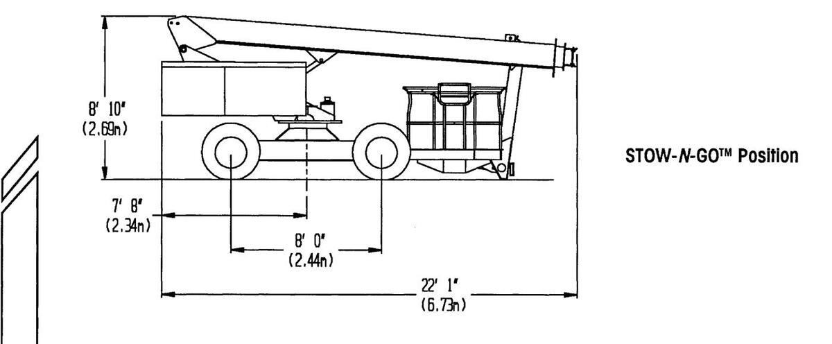
| Stowed Length (STOW- N -GO ™ Position) | 22 Ft 1 In. / 6.73 M | ||
| Stowed Height | 8 Ft 10 In. / 2.69 M | ||
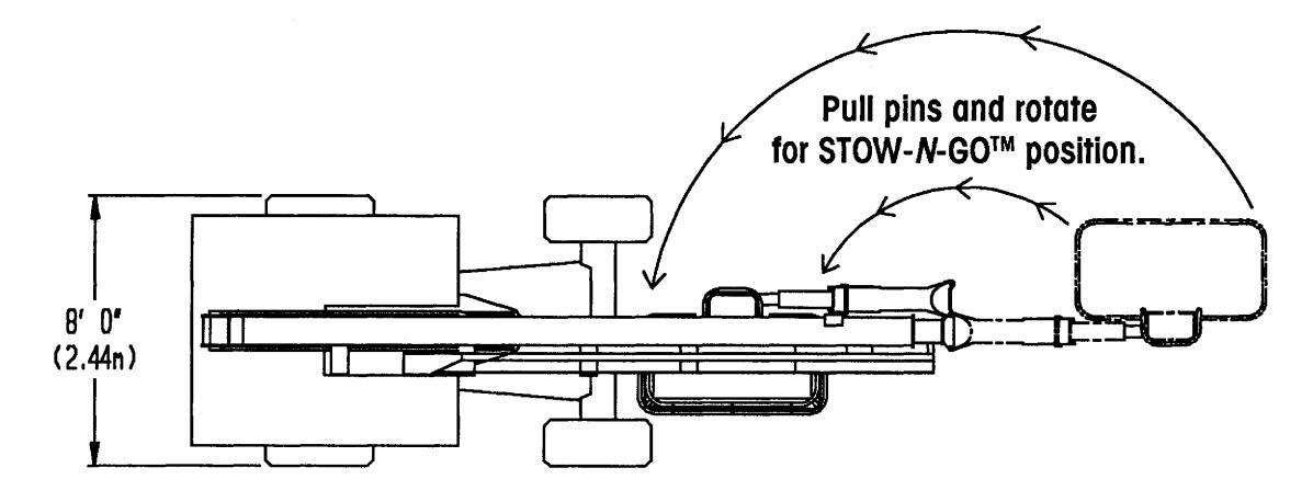
| Machine Width | 8 Ft. 0 In. / 2.44 M | ||
| Wheelbase | 8 Ft 0 In. / 2.44 M | ||
| Ground Clearance | 10.7 In. / 27.2 cm | ||
| Gross Weight (Approx.) (Note 1) | 28,000 Lbs. / 12,700 Kg | ||
| Maximum Travel Speed: | |||
| Boom Stowed (Note 1) | 2.5 MPH / 4.0 KPH | ||
| Boom Extended or Elevated | 0.5 MPH / 0.8 KPH | ||
| Outside Turning Radius | 16 Ft 10 In. / 5.13 M | ||
| Gradeability (On Hard Surface) (Note 1) | 1 5° / 27% | ||
| Platform Rotation | 180° | ||
| Superstructure Rotation | 360° continuous, either direction | ||
| Tire Size | 15-19.5 (14 Ply) | ||
| Tire Pressure (not applicable to foam filled tires) | 105 PSI / 7.24 Bar / 7.38 Kg/cm 2 | ||
| Maximum Hydraulic Pressure | 3000 PSI / 206 Bar / 210 Kg/cm 2 | ||
| Hydraulic Tank Capacity | 35 Gal. / 132.5 Liters | ||
| Fuel Capacity: | |||
| Gas or Diesel | 35 Gal. / 132.5 Liters | ||
| Propane | 30 Lbs. / 14 Kg | ||
| Swing Bearing Bolt Torque | 320 Ft Lbs. / 4 34 Nm / 44.2 Kg-m | ||
| Wheel Lug Nut Torque (Drive and Steer Axles) | 220 Ft Lbs. / 298 Nm / 30.4 Kg-m | ||
| Drive Hub Bolt Torque | 170 Ft Lbs. / 231 Nm / 23.5 Kg-m | ||
| Electrical System | Two 12 Volt DC Batteries | ||
| Engine Availability: | |||
| Standard: Wisconsin W41770, 35 HP (26.1 Kw), Air Cool | led, Gasoline | ||
| Optional: Wisconsin W41770, 35 HP (26.1 Kw), Air Cool | led, Dual Fuel | ||
| Wisconsin V-465, 65 HP (48.5 Kw), Air Cooled | , Gasoline or Dual Fuel (Std. 4WD) | ||
| Ford LSG 423, 63 HP (47.0 Kw), Liquid Cooled | , Gasoline or Dual Fuel | ||
| Deutz F3L 1011, 42 HP (31.3 Kw), Air Cooled, | Diesel Fuel | ||
| Deutz F4L 1011, 56 HP (41.7 Kw), Air Cooled, | Diesel Fuel | ||
| Detroit Diesel/ Perkins 104.22, 50 HP (37.3 Kw), Liquid Cooled, Diesel Fuel | |||
| Isuzu C-240, 56 HP (41.7 Kw), Liquid Cooled, | Diesel Fuel | ||
| Note 1: Weight and performance shown represent typical units, and s | hould be used as a general guideline | ||
| only. Many variables between machines can lead to significant dif | ferences in these factors. Accurate | ||
figures, when necessary for a particular application, can best be determined by testing of the specific unit.
MACHINE SPECIFICATIONS

MACHINE DIAGRAMS
MACHINE DIAGRAMS
RANGE DIAGRAM

CONVERSION CHART 100% 95% 90% 85% 80% 75% 75% 65% 60% 55% 60% 55% 60% 60
GENERAL ARRANGEMENT DIAGRAM

RP 66 REACH PLUS OPERATOR'S MANUAL
SAFETY
SECTION 1: SAFETY
[]

Table of Contents, Section 1
SAFETY
| Safety Symbols | |
|---|---|
| Safety Rules and Precautions | |
| Safety-Related Decals | |
| Safety and Control Decal Locations | |
| Safety and Control Deca Identification |

Page 1-2
SAFETY SYMBOLS
SAFETY SYMBOLS
This manual contains important information on the safe use of your SIMON Self-Propelled Aerial Work Platform. Your failure to read, understand and follow all safety rules, warnings and instructions will unnecessarily expose you and others to dangerous situations. For your safety and the safety of those around you, you must operate your aerial work platform as instructed in this manual.
You, the operator, are the single most important factor for safety when using any piece of equipment. Learn to operate your work platform in a safe manner.
To help you recognize important safety information, we have identified warnings and instructions that directly impact on safety with following signals:
A DANGER
"DANGER" INDICATES AN IMMINENTLY HAZARDOUS SITUATION WHICH, IF NOT AVOIDED, WILL RESULT IN DEATH OR SERIOUS INJURY. THIS SIGNAL WORD IS LIMITED TO THE MOST EXTREME SITUATIONS.
"WARNING" INDICATES A POTENTIALLY HAZARDOUS SITUATION WHICH, IF NOT AVOIDED, COULD RESULT IN DEATH OR SERIOUS INJURY.
A CAUTION
"Caution" indicates a potentially hazardous situation which, if not avoided, may result in minor or moderate injury. It is also used to alert against unsafe practices, and for property-damage-only situations.
One final note: The best method to protect yourself and others from injury or death is to use common sense. If you are unsure of any operation, don't start until you are satisfied that it is safe to proceed.
SAFETY RULES AND PRECAUTIONS
• ELECTROCUTION HAZARD!! THIS MACHINE IS NOT INSULATED!! Maintain safe clearance from electrical lines and apparatus. You must allow for machine sway (side to side movement) when elevated, and electrical line movement. This machine does not provide protection from contact with or proximity to an electrically charged conductor.
You must AVOID CONTACT between any part of the machine, or its load, and any electrical line or apparatus carrying up to 300 volts.
You must maintain a CLEARANCE OF AT LEAST 10 FEET (3.05 M) between any part of the machine, or its load, and any electrical line or apparatus carrying over 300 volts up to 50,000 volts. One foot (30.5 cm) additional clearance is required for every additional 30,000 volts.
DEATH OR SERIOUS INJURY will result from contact with, or inadequate clearance from, any electrically charged conductor.
- Read and understand all safety and control information found on the machine and in this manual before operating the unit.
- Only trained, competent personnel should operate the aerial work platform.
- Be aware of all Government and Local rules which may apply to this machine and its safe operation.
- Approved safety belts must be worn at all times when operating the unit from the platform. In addition, approved headgear and other protective equipment must be worn as required. (In the U.S.A., OSHA approved equipment is required. For other countries, the appropriate equivalent government body should be consulted.)
- NEVER fasten safety belt to an adjacent structure while on the work platform.
- Make sure that entry gate to platform is secured before operating unit from the platform.
- DO NOT block the foot pedal or any function control in the operating position.
- DO NOT exceed the platform capacity of the unit in any configuration. Review the section titled "MACHINE SPECIFICATIONS", earlier in this manual, regarding this model's capacities and dimensions.
Page 1-4
SAFETY RULES
RP 66 REACH PLUS OPERATOR'S MANUAL
SAFETY RULES
SAFETY RULES AND PRECAUTIONS (CONTINUED)
A DANGER
- SECURE all tools and other loose items to prevent injury to persons working on or below the work platform.
- DO NOT use scaffolding, ladders or similar items to extend your reach while on the work platform.
- DO NOT attempt to climb down the boom assembly, if the unit fails while the operator's platform is raised or extended.
- Since the machine may be operated from its ground controls, precautions should be taken to prevent unauthorized personnel from operating the work platform with the ground controls while the platform is in use.
- The "UNPOWERED EMERGENCY MOVEMENT" procedure (described later in this manual) requires releasing the torque hubs, which results in there being no means to stop the unit's travel. Simon recommends using this procedure only in cases of emergency, and only for a short distance. Be on guard against unit runaway on sloping surfaces. Movement speed shall not exceed 1 M.P.H. (1.6 K.P.H.).
- DO NOT attempt to open any hydraulic line or component without first relieving all system pressures and shutting off fluid flow from the tank.
- DO NOT allow anyone to tamper with, service or operate the machine from the ground control station while personnel are on the platform, except in an emergency.
- DO NOT alter, modify or disable any safety devices or interlocks.
- DO NOT refuel the unit near sparks or open flames. Gasoline and propane vapors, and Diesel fuel fumes are highly explosive.
- DO NOT use the aerial work platform outdoors in electrical storms or in high wind situations.
- DO NOT raise the aerial work platform unless the unit is on a firm, level surface.
- ENSURE THAT the STOW-N-GO™ lock pins are in place and anchored.
SAFETY RULES AND PRECAUTIONS (CONTINUED)
A DANGER
- Use caution to prevent ropes, cords, hoses, etc. from becoming entangled in the unit's boom sections when being raised, lowered or repositioned.
- Ensure that the area surrounding the mobile platform is clear of personnel and equipment before: driving the unit; or raising, lowering or extending the boom; or swinging the superstructure; or, rotating or tilting the platform.
- Maintain a safe distance from overhead and ground obstacles, debris, drop-offs, holes, depressions, electrical wires and other hazards to travel.
- Limit travel speed according to conditions of the ground surface, congestion, slope, location of personnel or any other factors that could cause hazard of collision or injury to personnel.
- DO NOT sit, stand or climb on platform rails.
- DO NOT operate this machine while under the influence of any drugs or alcohol.
- DO NOT operate this machine if you are bothered by heights, seizures, or dizzy spells.
- DO NOT indulge in stunt driving or horseplay while operating this machine.
AWARNING
- Complete the "Operational Checklists" found in this manual (see Table of Contents) at designated intervals.
- Ensure that the machine is in "LOW" drive speed while unloading from a truck or trailer.
- Always attach the unit to a winch when loading or unloading from a truck or trailer. Simon does not recommend unassisted loading or unloading of any aerial work platform.
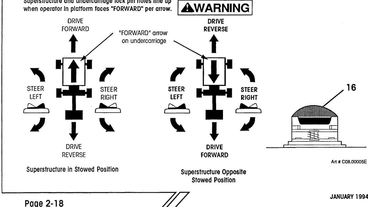
- With the superstructure swung away from the stowed position, use caution when selecting travel or steering direction. Travel and steer direction will be opposite switch or lever movement. Refer to the large "FORWARD" arrows on the undercarriage of the unit or the location of the superstructure lockpin hole for travel orientation.
Page 1-6
SAFETY RULES
SAFETY RULES AND PRECAUTIONS (CONTINUED)
- Check fuel system for leaks or damaged fuel lines before operating unit. If any damage is found, contact your supervisor immediately. Machine shall be removed from service until diagnosis and any necessary repairs have been completed.
- Actuation of the red "EMERGENCY STOP" button will apply brakes immediately, causing unexpected platform movement as the machine comes to a sudden stop. Brace yourself.
- Whenever disengaging the drive torque hubs or before disconnection from towing vehicle, ensure that the unit cannot roll.
- Immediately report any erratic noises, vibrations or malfunctions of the unit to supervisor. Machine shall be removed from service until diagnosis and any necessary repairs have been completed.
- Operating this equipment without all safety and control decals in place can be hazardous.
A CAUTION
- For transporting the machine, the platform must not be tied to the trailer bed in any way.
- Be sure to turn all hydraulic valves back "ON" before starting the machine, or extensive pump damage will occur.
- DO NOT exceed the maximum platform horizontal pull of 100 pounds (45.4 kg).
- DO NOT use the boom or platform as a crane to lift oversized or hanging loads.
- DO NOT raise, extend, retract, tilt, rotate, or lower the platform into stationary objects, as this will cause damage to mechanical and hydraulic components.
- DO NOT use the platform or boom functions to push or tow the unit or another vehicle.
- Avoid sudden braking or steering, go slowly and leave more maneuvering room during cold weather operation until the machine is warm.
SAFETY-RELATED DECALS

10-130600 Decal, "DANGER" (Hazard listing at ground controls)
Page 1-8
SAFETY RELATED DECALS

10-142100 Decal, "DANGER" (Hazard listing at platform controls)

10-148300 Decal, Platform Capacity [4-1/2" (114 mm) wide]
SAFETY AND CONTROL DECAL LOCATIONS
OPERATING THIS EQUIPMENT WITHOUT ALL SAFETY AND CONTROL DECALS IN PLACE CAN BE HAZARDOUS.
If any of these items are damaged or missing, replace them immediately. Decals are shown for standard machine. Optional equipment may change the decal locations.

PLACARD LOCATIONS
SAFETY AND CONTROL DECAL DESCRIPTIONS
| item | |||||
|---|---|---|---|---|---|
| No. | Part Number | Description | Qty. | ||
| 1 | 10-169700 Placard, Ground Control Valves | ||||
| 2 | 10-144300 | Placard, Ground Electrical Controls | 1 | ||
| 3 | 10-131500 | Placard, Remote Control Pendant | 1 | ||
| 4 | 10-130600 | Decal "DANGER" (Hazard listing at Ground Controls) | 1 | ||
| 5 | 10-012600 | Decal, "OPEN HYDRAULIC TANK VALVES " | 1 | ||
| 6 | 10-007200 | Decal, "DISENGAGE LOCK PIN " | 2 | ||
| 7 | 10-148300 | Decal, "PLATFORM CAPACITY 500 LBS (225 kg)", | |||
| [4-1/2" (114 mm) wide] | 2 | ||||
| 8 | 10-145100 | Decal, "DANGER" ("Electrocution ") | 2 | ||
| 9 | 10-117900 | Placard, "GASOLINE ONLY" | |||
| (for versions with gasoline engine) | 1 | ||||
| 10-151100 | Placard, "DIESEL FUEL ONLY" | ||||
| (for versions with optional Diesel engine) | 1 | ||||
| 10 | 10-151300 | Placard, "HYDRAULIC FLUID ONLY " | 1 | ||
| 11 | 10-012900 | Decal, "FORWARD" with Arrow | 2 | ||
| 12 | 10-169100 | Placard, Platform Controls | 1 | ||
| 13 | 10-147400 | Decal, Platform Level and Rotate Controls | 1 | ||
| 14 | 10-142100 | Decal "DANGER" (Hazard listing at Platform Controls) | 1 | ||
| 15 | 10-145300 | Decal, "PLATFORM CAPACITY 500 LBS (225 kg)", | |||
| [18-1/4" (464 mm) wide] | 1 | ||||
SECTION 2: OPERATION

Table of Contents, Section 2
OPERATION
| Unloading Procedures | 2-3 |
|---|---|
| Primary Machine Components | 2-7 |
| Operator Controls | |
| Ground Controls | 2-8 |
| Remote Control Pendant | 2-12 |
| Platform Controls | 2-14 |
| Start-up Procedures | |
| Shift Checks | 2-20 |
| Machine Start-up | 2-21 |
| Ground Operation and Checks | 2-22 |
| Platform Operation and Checks | 2-27 |
| Optional Emergency Descent Valve Operation and Checks | 2-32 |
| Operation | |
| Cold Weather Operation | 2-33 |
| Driving and Steering | 2-34 |
| Braking | 2-35 |
| Boom, Superstructure and Platform | 2-35 |
| Gasoline Engine Operation | 2-36 |
| Dual Fuel Engine Operation | 2-36 |
| Diesel Engine Operation | 2-37 |
| Shut-down Procedures | 2-38 |
| Transporting The Unit | |
| Towing Procedures | 2-39 |
| Truck or Trailer Transport | |
| Boom in STOW- N -GO™ Mode | 2-40 |
| Boom in Conventional Mode | 2-43 |
| Emergency System and Procedures | |
| Emergency Electrical Pump | 2-45 |
| Unpowered Emergency Movement | 2-46 |
| Optional Emergency Descent Valves | 2-47 |
| Emergency Lowering | 2-47 |
| - |
[[]
OPERATION
UNLOADING PROCEDURES
A WARNING
TO AVOID SERIOUS PERSONAL INJURY OR DEATH, ENSURE THAT THE MACHINE IS IN "LOW" DRIVE SPEED WHILE UNLOADING FROM A TRUCK OR TRAILER.
- 1. Inspect the outside of the unit for damage (including the underside). Inspect all hoses, boom sections and cables for chafing or shipping damage. Confirm that all wheel lug nuts and swing bearing bolts are tight (refer to specifications).
- 2. Remove the pin that locks the superstructure to the undercarriage near the swing bearing. Stow the lock pin in the location provided nearby.
- 3. Unlock and open both side compartments. Inspect all fuel, electrical and hydraulic connections for damage and security.
- 4. Connect battery cables to batteries if required. Check electrolyte level.
- 5. Open the fuel tank valve and check fuel level.
- 6. Check engine oil level, and add as required per engine manufacturer's recommendations.
- 7. Check fluid level at the sight gauge on the hydraulic tank, and add fluid as required (see Lubrication Chart). Check that shutoff valves on the hydraulic tank are open.
- 8. Close side compartment covers.
- 9. Attach the unit to a winch for the unloading procedure.
ALWAYS USE A WINCH TO ASSIST LOADING OR UNLOADING THE UNIT FROM A TRUCK OR TRAILER. CONNECT WINCH CABLE TO THE TIE DOWN LUGS ON THE UNDERCARRIAGE. UNASSISTED LOADING OR UNLOAD-ING OF ANY MOBILE PLATFORM IS NOT RECOMMENDED.
READ AND UNDERSTAND ALL SAFETY, CONTROL AND OPERATING INFORMATION FOUND ON THE MACHINE AND IN THIS MANUAL BEFORE OPERATING THE UNIT.
UNLOADING PROCEDURES (CONTINUED)
10. Start engine, using the ground controls.
NOTE: Refer to Start-up Procedures and Operator Controls Descriptions in this section.
After a brief warm-up period, select the "HI" engine speed. On the remote control pendant, press and hold the pump selector toggle switch to "MAIN" position, but do not operate any drive or boom function. This is called "deadheading", and will lead to maximum system pressure registering on the gauge at the ground control valve assembly. Refer to the "Machine Specifications" section of this manual for the "Maximum Hydraulic Pressure" for this unit.
Select the "LOW" engine speed and allow the engine to slow to idle speed.
11. Remove tie downs from the base of the jib boom ONLY.

WITH BOOM OUT OF "OPERATIONAL MODE" POSITION, DO NOT PLACE ANY LOAD IN THE PLATFORM.
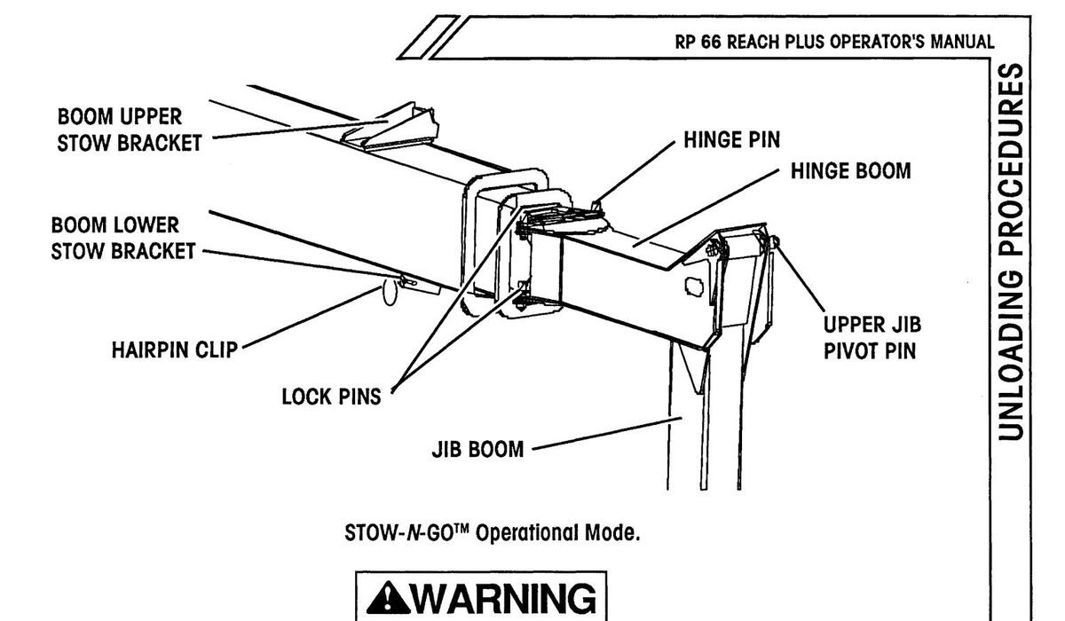
NOTE: If boom is in STOW- N -GO™ storage mode (see illustration):
- a. Platform controls are disabled until the hinge boom is secured to main boom with upper and lower lock pins. From ground controls, raise boom to horizontal. Disconnect lower stow bracket from jib boom and return bracket and hairpin clip to stowed position.
- b. Swing platform around so that the hinge boom aligns with the main boom (see "Operational Mode" illustration).
- c. Position jib out at approximately 45° to main boom and lower main boom so jib is slightly raised above bed of truck or trailer.
- d. Remove boom lock pins from stowed position, align hinge and main boom holes and insert boom lock pins to secure hinge boom to main boom.
If hinge and main boom holes do not line up, slightly lower main boom onto truck or trailer bed to apply pressure on jib boom.
e. Secure hinge boom to main boom with both boom lock pins and hairpin clips (attached).
UNLOADING PROCEDURES (CONTINUED)
- 12. Turn engine off.
- 13. Remove remaining machine tie downs. Remove wheel chocks, if used.
- 14. Turn the key switch to "PLATFORM CONTROLS".
- 15. Enter the platform, and restart the engine using the platform controls. Select the "OPERATING" engine speed, and test all platform functions.
- 16. Raise the boom so that the platform will clear any obstacles as the machine is driven down the loading ramp.
- 17. Carefully drive the unit off the truck or trailer with the assistance of a winch. The brakes are automatically released for driving, and will automatically apply when the unit stops.
- 18. Before placing the unit into service, all operators must read and understand the contents of this Operator's Manual.
Upon initial unloading of the machine the Receipt Inspection Adjustment Report or Predelivery Inspection Adjustment Report must be completed and returned in order to activate the Simon Limited Warranty.
An Operator's Manual and a Receipt Inspection Adjustment Report are included with each machine leaving the factory.
Page 2-6


RP 66 REACH PLUS OPERATOR'S MANUAL
OPERATOR CONTROLS
OPERATOR CONTROLS DESCRIPTION (GROUND CONTROL)
| ltem | Control | Location | Description |
|---|---|---|---|
| 1. |
Emergency Stop
Button |
Ground Electri-
cal Panel |
Used to stop all functions in an emergency. Push for emergency stop. Pull or rotate clockwise to reset, depending on style used. |
| 2. | Circuit Breaker |
Ground Electri-
cal Panel |
Pops out when the 12 Volt electrical circuit is over-
loaded. Push in to reset. |
| 3. |
Choke/
Glow Plug Button |
Ground Electri-
cal Panel |
Choke button for gas or dual fuel engines. Press and hold while starting a cold engine. |
| Glow plug button for some Diesels. Press and hold (if so equipped) to preheat combustion chamber before starting a cold engine. | |||
| 4. |
Main Power Key
Switch |
Ground Electri-
cal Panel |
Three position main power "On/Off" switch. Straight up position is "OFF". |
|
Turn key left (counterclockwise) one position to turn
power "ON" for ground control operation. Turn key right (clockwise) one position to turn power "ON" for plat- form control operation. |
|||
| With key switch "OFF", the key may be removed to prevent unauthorized operation. | |||
| 5. |
Engine Start
Button |
Ground Electri-
cal Panel |
Press push button to engage engine starter. Release
button immediately upon engine start. If the engine does not start within 10 seconds, the main power key switch must be turned off and then on again to start. |
| NOTE: Main power key switch must be in "GROUND" position. | |||
| 6. |
Engine RPM
(Throttle) Switch |
Ground Electri-
cal Panel |
Flip toggle down for "LO" (idle) engine speed. Flip toggle up for "HI" engine speed. |
| IMPORTANT: Engine should not be in "LO" speed while operating any hydraulic functions. |
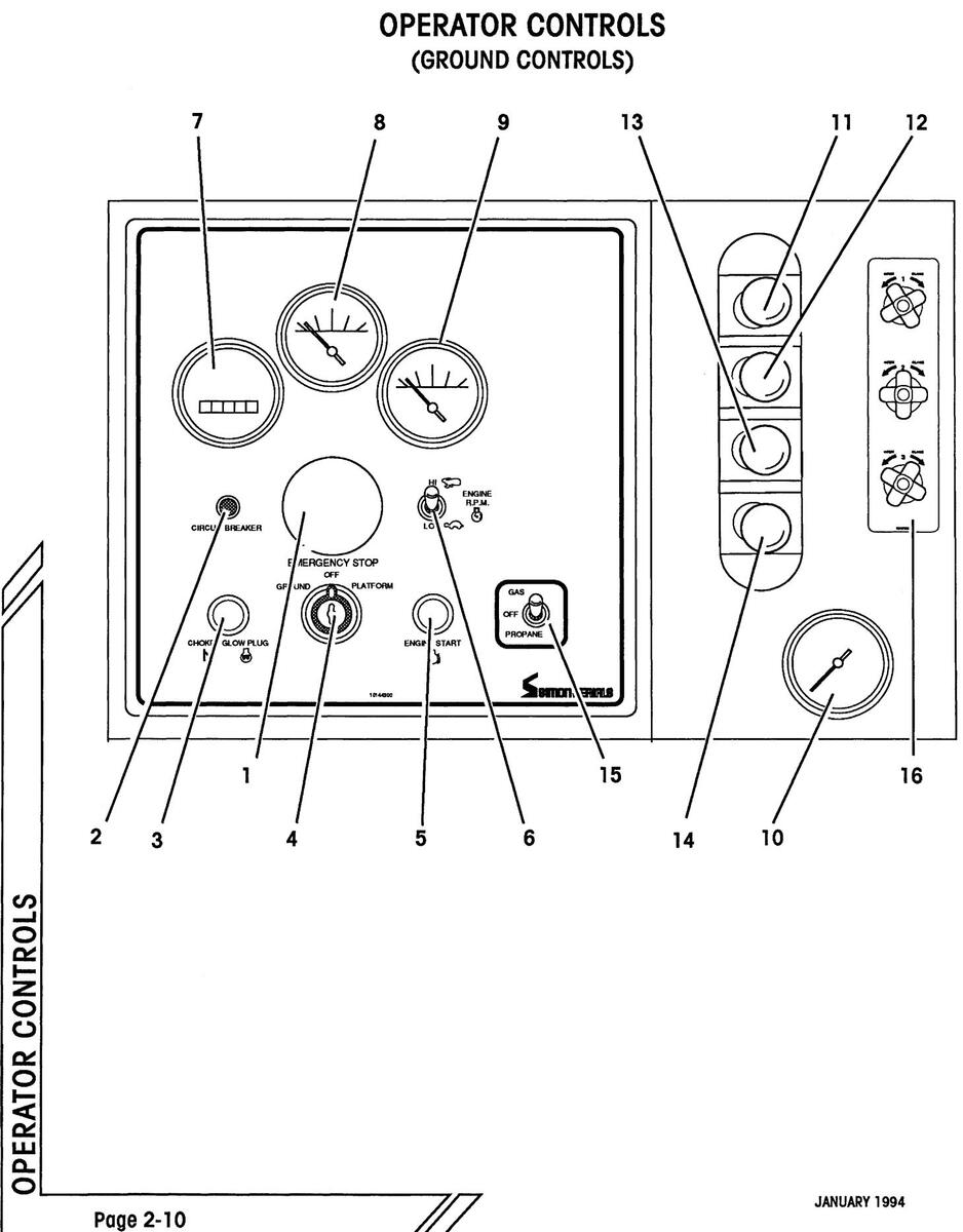
RP 66 REACH PLUS OPERATOR'S MANUAL
OPERATOR CONTROLS
OPERATOR CONTROLS DESCRIPTION (GROUND CONTROLS, CONTINUED)
| ltem | Control | Location | Description |
|---|---|---|---|
| 7. | Hour Meter |
Ground Electri-
cal Panel |
Indicates total elapsed time that the engine has been operated in hours and tenths. |
| 8. | Volt Meter |
Ground Electri-
cal Panel |
Indicates electrical system voltage. |
| 9. |
Engine Oil Pres-
sure Gauge |
Ground Electri-
cal Panel |
Indicates engine oil pressure. |
| 10. |
Hydraulic Fluid
Pressure Gauge |
Beneath Ground
Valves |
Indicates hydraulic fluid pressure. |
| 11. |
Swing Control
Lever |
Right of Electri-
cal Panel |
Lever controls the rotation of the superstructure on the
undercarriage. Move lever left to swing superstructure to the left (clockwise). Move lever right to swing to the right (counterclockwise). The superstructure can rotate 360°, continuously in either direction. |
| 12. | Boom Lift Lever |
Right of Electri-
cal Panel |
Lever controls the raising and lowering of the main boom. Move lever right to raise main boom, and left to lower. |
| 13. |
Boom Telescope
(Extend) Lever |
Right of Electri-
cal Panel |
Lever controls the boom telescope function. Move lever left to extend boom. Move lever right to retract boom. |
| 14. |
"Reach Plus"
Jib Boom Lever |
Right of Electri-
cal Panel |
Lever controls the raising and lowering of the jib boom.
Move lever right to raise jib boom, and left to lower. |
| 15. |
Gas/ Off/ Propane
Switch (Optional) |
Ground Electri-
cal Panel |
Flip toggle up to use gasoline, down to use propane fuel. In "OFF" position, the engine is not supplied with fuel. |
| 16. |
Emergency
Descent Valves (Option) |
Right of Ground
Valves |
Available factory option for lowering and retracting
boom in cases of emergency. Refer to "Optional Emergency Descent Valves" later in this section for operation. |
OPERATOR CONTROLS (REMOTE CONTROL PENDANT)

Page 2-12
OPERATOR CONTROLS
OPERATOR CONTROLS

| ltem | Control | Location | Description |
|---|---|---|---|
| 1. |
Pump Selector
Toggle Switch |
On Remote
Control Pendant |
Push up to "MAIN" position and hold to activate engine
powered hydraulic pump, allowing operation of any of the hydraulic functions (drive, steer or boom move- ment) from the ground. |
| Push down to "EMERGENCY" position and hold to activate battery powered hydraulic pump, allowing operation of boom functions should the engine powered hydraulic pump be disabled. | |||
| 2. |
Drive Toggle
Switch |
On Remote
Control Pendant |
Push up and hold to travel forward, down to travel backward. |

WHEN THE PLATFORM IS SWUNG OVER THE STEER-ING WHEELS, USE CAUTION WHEN SELECTING THE TRAVEL DIRECTION. TRAVEL DIRECTION WILL BE OPPOSITE SWITCH MOVEMENT.
3. Steer Toggle On Remote Switch On Remote Control Pendant Control Pendant On Remote Control Pendant On Remote Control Pendant On Remote Control Pendant On Remote Control Pendant On Remote Control Pendant On Remote Control Pendant On Remote Control Pendant On Remote Control Pendant On Remote Control Pendant On Remote Control Pendant On Remote Control Pendant On Remote Control Pendant On Remote Control Pendant On Remote Control Pendant On Remote Control Pendant On Remote Control Pendant On Remote Control Pendant On Remote Control Pendant On Remote Control Pendant On Remote Control Pendant On Remote Control Pendant On Remote Control Pendant On Remote Control Pendant On Remote Control Pendant On Remote Control Pendant On Remote Control Pendant On Remote Control Pendant On Remote Control Pendant On Remote Control Pendant On Remote Control Pendant On Remote Control Pendant On Remote Control Pendant On Remote Control Pendant On Remote Control Pendant On Remote Control Pendant On Remote Control Pendant On Remote Control Pendant On Remote Control Pendant On Remote Control Pendant On Remote Control Pendant On Remote Control Pendant On Remote Control Pendant On Remote Control Pendant On Remote Control Pendant On Remote Control Pendant On Remote Control Pendant On Remote Control Pendant On Remote Control Pendant On Remote Control Pendant On Remote Control Pendant On Remote Control Pendant On Remote Control Pendant On Remote Control Pendant On Remote Control Pendant On Remote Control Pendant On Remote Control Pendant On Remote Control Pendant On Remote Control Pendant On Remote Control Pendant On Remote Control Pendant On Remote Control Pendant On Remote Control Pendant On Remote Control Pendant On Remote Control Pendant On Remote Control Pendant On Remote Control Pendant On Remote Control Pendant On Remote Control Pendant On Remote Control Pendant On Remote Control Pendant On Remote Control Pendant On Remote Control Pendant On Remote Control Pendant On Remote Control Pendant On Remote Control Pendant On Remote Control Pen
WITH THE PLATFORM OVER THE STEERING WHEELS, USE CAUTION WHEN SELECTING THE STEERING DIRECTION. STEER DIRECTION WILL BE OPPOSITE SWITCH MOVEMENT.
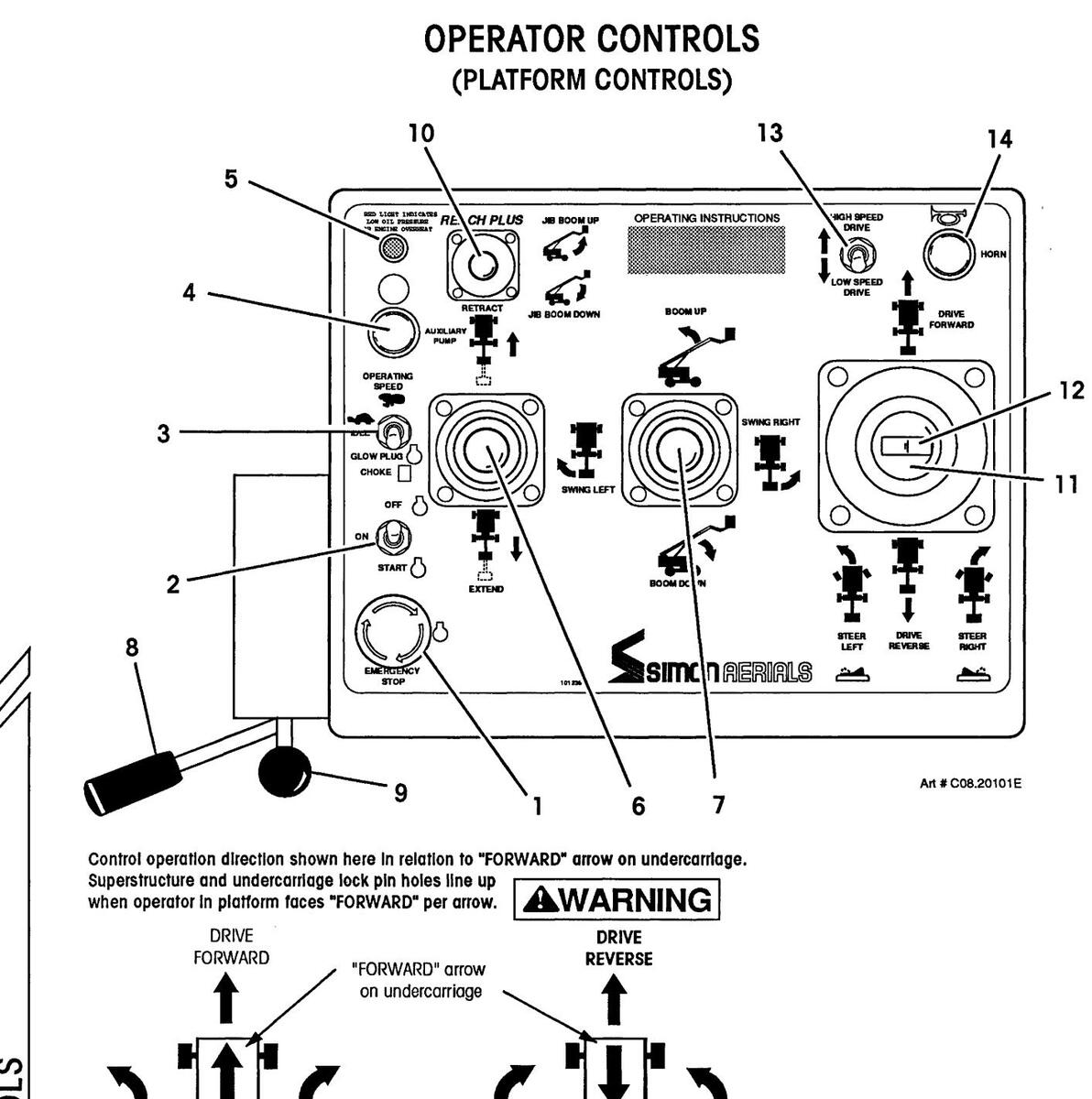

RP 66 REACH PLUS OPERATOR'S MANUAL
OPERATOR CONTROLS
OPERATOR CONTROLS DESCRIPTION (PLATFORM CONTROLS)
| ltem | Control | Location | Description |
|---|---|---|---|
| 1. |
Emergency Stop
Button |
On Platform
Console |
Used to stop all functions in an emergency. Push for emergency stop. Pull or rotate clockwise to reset, depending on style used. |
| 2. |
Off/ On/ Start
Switch |
On Platform
Console |
Three position toggle switch. Up is "OFF". Move to center position to turn ignition "ON", down to engage starter. If the engine does not start within 10 seconds, switch must be turned off and then on again to start. |
| IMPORTANT: Engine will not start with foot pedal depressed. | |||
|
3. Glow Plug
Choke/ Id |
Glow Plug/
Choke/ Idle/ Operating Speed |
Blow Plug/ On Platform
Choke/ Idle/ Console Operating Speed Switch |
Flip toggle to center position for low (idle) engine speed, up for high (operating) engine speed |
| Switch | IMPORTANT: Machine should not be in low (idle) speed while operating any hydraulic functions. | ||
| For gasoline engines, press toggle to down position and hold when starting a cold engine. | |||
| For some Diesel engines (equipped with glow plugs), press and hold to preheat combustion chamber before starting a cold engine. | |||
| 4. |
Auxiliary Pump
Push Button |
On Platform
Console |
Press and hold to activate battery powered hydraulic pump, allowing operation of boom or platform func-
tions should the engine powered hydraulic pump be disabled. |
| 5. |
Engine Warning
Indicator |
On Platform
Console |
Red light that indicates low engine oil pressure or high
engine coolant temperature. Engine will shut down automatically if condition does not correct itself in approximately 10 seconds. |
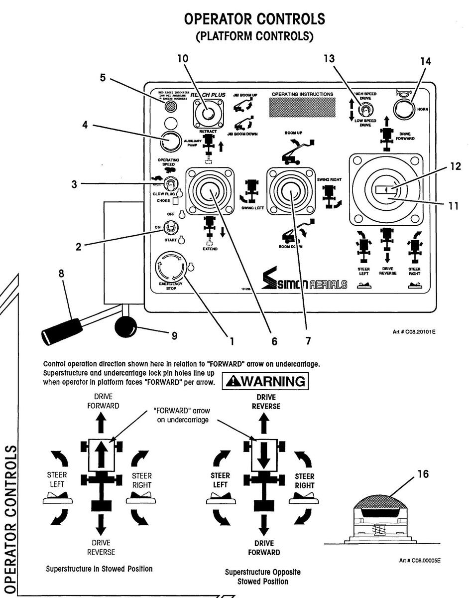
Page 2-16
OPERATOR CONTROLS
OPERATOR CONTROLS DESCRIPTION (PLATFORM CONTROLS, CONTINUED)
| Item | Control | Location | Description |
|---|---|---|---|
| 6. |
Boom Telescope
Lever |
On Platform
Console |
Lever controls the boom telescope function. Pull back to extend boom. Push forward to retract boom. Boom speed will be proportional to handle movement. |
| 7. |
Main Boom Lift
and Swing Control Lever |
On Platform
Console |
Push lever forward to raise main boom. Pull lever back to lower main boom. Boom speed will be proportional to handle movement. |
|
Push lever to right to swing superstructure to right
(counterclockwise). Push lever to left to swing left (clockwise). Superstructure can rotate 360° continu- ously in either direction. Swing speed will be propor- tional to handle movement. |
|||
| 8. |
Platform Rotate
Lever |
On Platform
Console |
Operate lever in direction of desired platform rotation.
Pull lever counterclockwise to rotate platform counter- clockwise. Push lever clockwise to rotate platform clockwise. |
| 9. |
Platform Leveling
Lever |
On Platform
Console |
Push lever forward to tilt platform forward. Pull lever back to tilt platform back. |
| 10. |
"Reach Plus"
Jib Boom Lever |
On Platform
Console |
Push lever forward to raise jib boom. Pull lever back to lower jib boom. Boom speed will be proportional to handle movement. |
OPERATOR CONTROLS

Control operation direction shown here in relation to "FORWARD" arrow on under Superstructure and undercarriage lock pin holes line up
| RP 6 | 66 | REAC | H P | LUS | OPER | ATOR'S | MANUAL |
|---|---|---|---|---|---|---|---|

| OP | ERATOR COI |
NTROLS DESCRIPTION
ONTROLS, CONTINUED) |
NTROLS | |
|---|---|---|---|---|
| ltem | Control | Location | Description | ပိ |
| 11. |
Drive Control
Lever |
On Platform
Console |
Controls forward and reverse machine travel at a speed proportional to handle movement. | ATOR |
|
WITH PLATFORM SWUNG OVER STEERING
WHEELS, USE CAUTION WHEN SELECTING THE TRAVEL DIRECTION. TRAVEL DIREC- TION WILL BE OPPOSITE DRIVE CONTROL LEVER MOVEMENT. |
OPER | |||
| 12. | Steer Switch |
On end of Drive
Control Lever |
Move switch left and hold to turn steer wheels to left, and right to turn steer wheels to right. Push and hold in opposite direction to straighten wheels. | |
|
WITH PLATFORM SWUNG OVER THE STEER-
ING WHEELS, USE CAUTION WHEN SE- LECTING THE STEERING DIRECTION. STEER- ING DIRECTION WILL BE OPPOSITE STEER SWITCH MOVEMENT. |
||||
| 13. |
Drive Speed
Switch |
On Platform
Console |
Press switch up for "HIGH" machine travel speed, down
for "LOW" speed. High speed travel is available only while boom is below horizontal and extended less than 9 feet (2.7 Meters). |
|
| 14. | Horn Button |
On Platform
Console |
Press button to sound warning horn. | |
| 15. |
Light Switches
(Optional) |
On Lights
(Not Shown) |
Flip switch to turn head lights on and off. Lights are
powered by gel cell battery located on the right side of platform console. Lights blink when battery is close to discharge (approximately 45 minutes). |
|
| 16. | Foot Pedal Switch |
On Platform
Floor |
Must be depressed to activate main hydraulic pump,
allowing operation of any hydraulic function (drive, steer, boom or platform movement) from the platform. Depress pedal before selecting function. |
START-UP PROCEDURES
SHIFT CHECKS
Before the Simon RP 66 Work Platform is put into use each shiff, the following checks should be completed to make sure that the machine is safe and in good condition.
Refer to check lists at back of this manual for periodic maintenance requirements and additional procedures for severe duty applications:
- Visually inspect all machine components, i.e. missing parts, torn or loose hoses, hydraulic fluid leaks, torn or disconnected wires, flat or damaged tires, etc. Both compartment doors can be opened to inspect components inside.
- ____ Check engine oil and fuel levels.
- ____ Check engine coolant level (on liquid cooled units).
- Check battery electrolyte level and connections.
- ____ Check hydraulic fluid level with booms fully retracted and lowered.
- ____ Check that all shutoff valves on the hydraulic tank are open. When open, valve handles will be parallel with the length of the valve.
The shutoff values on the hydraulic tank must be left open at all times, except during repairs or transport. If one or more of these values are closed when the unit is running, extensive pump damage will occur.
- ____ Check wheel lug nuts for tightness. Check tire pressure (see Specification page).
- ____ Check hoses and cables for worn areas.
- ____ Check hose carrier to make sure that it is not bent or sagging.
- ____ Inspect safety belt connections and check for worn areas on the belts.
- ____ Check platform rails and safety gate latch for damage.
- ____ Check pivot pins for security.
- ____ Check that all warning and instructional labels are legible and secure.
Page 2-20
START-UP PROCEDURES
START-UP PROCEDURES
MACHINE START-UP
A DANGER
ALL OPERATORS MUST THOROUGHLY READ AND UNDERSTAND THE "SAFETY RULES AND PRECAUTIONS" SECTION OF THIS MANUAL PRIOR TO OPERATING THE MACHINE.
A COMPLETE VISUAL INSPECTION OF THE MACHINE MUST BE PER-FORMED PRIOR TO OPERATIONAL CHECKS.
- Disengage lock pin before swinging the superstructure.
- Ensure that emergency stop buttons on ground control panel and platform control console are disengaged. Pull out or twist to reset, depending on style.
- Ensure that engine RPM toggle switch is set to "LOW".
- Turn the main power key switch to the "GROUND" position to energize the electrical system.
- Push down on each of the three fastened corners of the tilt alarm located behind the electrical box. The alarm should sound as each corner is pressed beyond 5 degrees.
- While starting a cold engine, for gasoline or dual fuel engines, press choke button, or
for some optional Diesel engines, press glow plug button, and hold it there for 30 to 45 seconds prior to engaging starter motor.
- Press and hold engine start button to start engine. After a brief warm-up period, select the "HI" engine speed setting with the engine RPM toggle switch.
- On the remote control pendant, press and hold the pump selector toggle switch to "MAIN" position, but do not operate any drive or boom function. This is called "deadheading", and will lead to maximum compensator setting of the pump system pressure registering on the gauge at the ground control valve bank assembly. Refer to the "Machine Specifications" section of this manual for the "Maximum Hydraulic Pressure" for this unit.
- Check that the hydraulic pressure is as stated in the "Machine Specifications" of this manual.
GROUND OPERATION AND CHECKS

With boom fastened in "STOW- N -GO™ Storage mode" position (see illustration), do not operate boom controls or place any load in the platform.

Page 2-22
STARTUP PROCEDURES
STARTUP PROCEDURES
With boom in operational mode:
AWARNING
BE SURE BOOM TRAVEL AREA IS CLEAR OF OBSTRUCTIONS.
DO NOT OPERATE THE MACHINE IF THE FOLLOWING CHECKS REVEAL A DEFECT.
• Press and hold the pump selector toggle switch (on the pendant) to "MAIN" position.
IMPORTANT: The pump selector switch is a "Deadman" type control. If released, all machine movement will stop.
- Slowly pull the lift valve lever (on the superstructure) right to raise the main boom to the horizontal position. Function speed is proportional to distance lever is moved. Slowly return the lift lever to the center position.
-
Slowly pull the "Reach Plus" valve lever (on the superstructure) right to raise the jib boom. Function speed is proportional to distance lever is moved. Slowly return the "Reach Plus" lever to the center position.
- ____ Listen for any unusual noises.
- Check for any vibration while the boom travels up.
- ____ Check for uneven or jerky operation.
- ____ Check for hydraulic leaks.
- Check pivot pin security. Make sure that all retaining bolts and rings are in place on the pin locking point, and have not sheared off.
-
Slowly pull the telescope valve lever (on the superstructure) left to extend the boom to the end of its movement. Function speed is proportional to distance lever is moved. Slowly return telescope lever to center position. Release pump selector toggle switch.
- ____ Listen for any unusual noises.
- Check for any vibration while the boom extends.
- ____ Check for uneven or jerky operation.
- ____ Check for hydraulic leaks.
- Inspect all sides of the boom sections visually for damage along their entire length.
GROUND OPERATION AND CHECKS (CONTINUED)
- Press and hold the pump selector toggle switch to "MAIN" position.
-
Slowly pull the lift valve lever right to raise the boom to the end of its movement.
- ____ Listen for any unusual noises.
- ____ Check for any vibration while the boom travels up.
- Check for uneven or jerky operation.
- ____ Check for hydraulic leaks.
- ____ Check pivot pin security. Make sure that all retaining bolts and rings are in place on the pin locking point, and have not sheared off.
- Slowly return the lift lever to the center position.
- Pull the main boom lever to the left to lower the boom slightly, while still pressing the pump selector toggle switch.
- Press the "Emergency Stop" button. All machine functions should stop, including the engine. Reset the emergency stop button.
With the engine off,
- Press the pump selector toggle switch to the "EMERGENCY" position.
-
Pull the main boom lever to the left to lower the boom slightly.
- _____ Listen for any unusual noises.
- Check for any vibration while the boom travels down.
- ____ Check for uneven or jerky operation.
- ____ Check for hydraulic leaks.
- Once boom movement has been established using the emergency pump, release the pump selector toggle switch. Restart engine.
-
Return the booms to their stowed positions by using the appropriate levers for "RETRACT" and "DOWN" in turn, while pressing the pump selector toggle switch to the "MAIN" position.
- ____ Listen for any unusual noises.
- Check for any vibration while the booms lower and retract.
- ____ Check for uneven or jerky operation.
- _____ Check for hydraulic leaks.
- _____ Report and repair any problem.
- Slowly return the valve levers to center position.
STARTUP PROCEDURES
RP 66 REACH PLUS OPERATOR'S MANUAL
STARTUP PROCEDURE
GROUND OPERATION AND CHECKS (CONTINUED)
-
Operate the swing valve lever slowly in each direction.
- Listen for any unusual noises.
- ____ Check for any vibration while the unit travels.
- ____ Check for uneven or jerky operation.
- ____ Check for hydraulic leaks.
- _____ Report and repair any problem.
- Slowly return the swing lever to center position.

TAKE EXTREME CARE WHEN SELECTING ANY OF THE TRAVEL FUNCTIONS FROM THE GROUND.
WITH THE PLATFORM SWUNG OVER THE STEERING WHEELS, TRAVEL AND STEERING DIRECTION WILL BE OPPOSITE TO DIRECTIONS INDI-CATED ON PLACARD.

GROUND OPERATION AND CHECKS (CONTINUED)
-
Press the drive toggle to the "FORWARD" position. The machine will move forward.
- ____ Listen for any unusual noises.
- ____ Check for any vibration while the unit travels.
- Check for uneven or jerky operation.
- _____ Check for hydraulic leaks.
- _____ Report and repair any problem.
- Push the steer switch in the left or right direction, and check for proper steering control. Note position of the platform to the steering wheels.
- Return the wheels to the straight ahead position by pressing the steer switch in the opposite direction. When wheels are straight, release the steer switch.
- Press the emergency stop button. All functions (including the engine) should stop immediately. Pull the button out or twist to reset. Restart engine.
- Press and hold the pump selector toggle switch. Press the drive toggle to "REVERSE". The machine will move in the backward direction.
- Release the drive toggle. The unit will come to a complete stop.
- Return the machine to the stowed position. Press the appropriate toggle switches or push valve levers in turn, while still pressing the pump selector toggle switch to "MAIN".
- Slowly return the valve levers to center position. Release the pump selector toggle switch.
NOTE: All machine operations will stop upon release of the pump selector toggle switch.
• Flip the engine throttle switch to "LOW", and allow the engine to slow to idle speed. Shut the engine off.
Page 2-26
STARTUP PROCEDURES
STARTUP PROCEDURES
PLATFORM OPERATION AND CHECKS
- Complete the Ground Operational Checks before performing the Platform Checks.
- Select "PLATFORM CONTROLS" with the ground/ platform key switch.

WITH BOOM OUT OF "OPERATIONAL MODE" POSITION, DO NOT PLACE ANY LOAD IN THE PLATFORM.
NOTE: To operate from platform, jib boom must not be in STOW- N -GO™ storage mode (see illustration). If boom is in STOW- N -GO™ storage mode, refer to instructions in "Ground Operation and Checks" section, earlier in this manual.

STOW- N -GO™ Storage Mode.
STOW- N -GO™ Operational Mode.
With boom in operational mode:
- Enter the platform. Close gate securely. Connect the safety belt to the platform.
- Ensure that the emergency button is released. Pull emergency button to reset.
- Move off/ on/ start toggle to center position to turn ignition "ON", down to engage starter, then release it to the "ON" position.
- Flip the engine throttle switch to "OPERATING SPEED".
PLATFORM OPERATION AND CHECKS (CONTINUED)
BE SURE BOOM TRAVEL AREA IS CLEAR OF OBSTRUCTIONS.
DO NOT OPERATE THE MACHINE IF THESE CHECKS REVEAL ANY DEFECT OR ABNORMALITY.
- Press the horn button briefly to check that the horn works. The horn acts as a signal for the tilt alarm as well as its normal warning function.
- Press the foot pedal mounted on the floor of the platform. (Activate foot pedal to operate any of the machine functions.)
- Slowly move the Reach Plus lever forward to the "JIB BOOM UP" position. The jib boom will start to rise. Function speed is proportional to the distance the lever is moved. Raise the jib boom to the fully raised position (approximately 10° above the main boom). Slowly return the control lever to the center position.
- Slowly move the middle lever forward to the "BOOM UP" position. The main boom will start to rise. Function speed is proportional to the distance the lever is moved. Raise the boom to the horizontal position. Slowly return the control lever to the center position.
-
Slowly move the left lever back to the "EXTEND" position. Extend boom out a short distance. Extend speed is proportional to the distance the lever is moved.
- ____ Listen for any unusual noises.
- ____ Check for any vibration while the boom telescopes out.
- ____ Check for uneven or jerky operation.
- ____ Check for hydraulic leaks.
- _____ Report and repair any problem.
- Slowly return the control lever to the center position.
-
Slowly move middle lever forward to "BOOM UP" position. The main boom will start to rise. Function speed is proportional to distance lever is moved.
- ____ Listen for any unusual noises.
- ____ Check for any vibration while the main boom travels up.
- Check for uneven or jerky operation.
- ____ Check for hydraulic leaks.
- _____ Report and repair any problem.
Page 2-28
STARTUP PROCEDURES
RP 66 REACH PLUS OPERATOR'S MANUAL
STARTUP PROCEDURES
- Slowly return the control lever to the center position.
-
Return the booms to the travel position by slowly operating the levers in the "RETRACT" and "BOOM DOWN" directions in turn.
- _____ Listen for any unusual noises.
- Check for any vibration while the booms lower and retract.
- ____ Check for uneven or jerky operation.
- ____ Check for hydraulic leaks.
- _____ Report and repair any problem.
- Slowly return the control levers to their center positions.
-
Slowly move the middle lever right to swing right (counterclockwise) and left to swing left (clockwise). Swing speed is proportional to distance lever is moved.
- ____ Listen for any unusual noises.
- ____ Check for any vibration while the unit rotates.
- ____ Check for uneven or jerky operation.
- ____ Check for hydraulic leaks.
- _____ Report and repair any problem.
- Slowly return the control lever to the center position.
-
Operate the platform rotate function by slowly moving the platform rotate control lever located on the left hand side of the control console. Move the lever in both directions.
- _____ Listen for any unusual noises.
- ____ Check for any vibration while the platform rotates.
- ____ Check for uneven or jerky operation.
- ____ Check for hydraulic leaks.
- Report and repair any problem.
- Return the platform to the center position. Return the control lever to the center position.
-
Operate the platform level function by slowly operating the platform level control lever, on the left side of the control console. Move the lever in both directions.
- ____ Listen for any unusual noises.
- ____ Check for any vibration while the platform tilts forward or back.
- ____ Check for uneven or jerky operation.
- ____ Check for hydraulic leaks.
- _____ Report and repair any problem.
- Return the platform to a level position. Return the control lever to the center position.
PLATFORM OPERATION AND CHECKS (CONTINUED)
• Switch the drive speed toggle switch to "LOW".
IMPORTANT: Jib should be raised for sufficient ground clearance.

WITH THE PLATFORM SWUNG OVER THE STEERING WHEELS, USE CAUTION WHEN SELECTING THE TRAVEL DIRECTION. TRAVEL AND STEERING DIRECTION WILL BE OPPOSITE CONTROL OPERATION.

OPERATION
PLATFORM OPERATION AND CHECKS (CONTINUED)
• Slowly move the drive control lever forward. The machine should smoothly accelerate in the direction of control lever movement.
Movement alarm sounds whenever the vehicle is in motion.
- ____ Listen for any unusual noises.
- ____ Check for any vibration while the unit travels.
- _____ Check for uneven or jerky operation.
- ____ Check for hydraulic leaks.
- ____ Report and repair any problem.
- Operate the steer switch and check for proper steering control. Note position of the platform to the steering wheels.
- Return the wheels to the straight ahead position.
- Slowly move the drive control lever backward. The machine will smoothly accelerate in the direction of the control lever movement.
Movement alarm sounds whenever the vehicle is in motion.
• Press emergency stop button. All functions (including engine) should stop immediately.
BRACE YOURSELF FOR UNEXPECTED PLATFORM MOVEMENT AS THE MACHINE COMES TO A SUDDEN STOP.
ACTUATION OF THE RED "EMERGENCY STOP BUTTON" WILL APPLY BRAKES IMMEDIATELY!
• Reset emergency stop button and restart engine.
PLATFORM OPERATION AND CHECKS (CONTINUED)
• Raise the main boom to above horizontal, and repeat the drive tests. Machine should travel a maximum of 0.5 M.P.H. (0.8 K.P.H.). This condition is referred to as "creep speed", and is the maximum rate of travel with the main boom raised or extended.
NOTE: At "creep speed", a tire makes one complete revolution in approximately twenty (20) seconds. If one revolution takes much less than this time, the machine must be adjusted to bring the "creep speed" back down to 0.5 M.P.H (0.8 K.P.H.).
- Return the machine to the straight ahead position, with main boom below horizontal and fully retracted. Position jib boom for adequate ground clearance for travel.
- Switch the drive speed toggle to "HIGH", and repeat the drive tests.
- Move all levers and switches back to their neutral positions. Release the foot pedal.
NOTE: All machine motion should stop upon release of the foot pedal.
• Flip off/ on/ start switch to the "OFF" position to shut off the engine.
OPTIONAL EMERGENCY DESCENT VALVE OPERATION AND CHECKS
The emergency descent values (if so equipped) are located next to the value bank assembly on the hydraulic side of the superstructure.
- With engine running, raise and extend the boom a short distance. Turn engine off.
-
With engine off:
- Close the top valve on the descent valves. This valve must be open during normal operation, or severe pump damage will occur.
- Open the second valve and keep the third valve closed to allow the boom to retract and lower. Gravity is used to retract and lower the boom, so the retract function will not work at near horizontal boom angles.
- Close the second valve and open the third valve to allow the boom to lower only.
- Once the boom is lowered, close the bottom and middle valves and open the top valve. The top valve must be open during normal operation, or severe pump damage will occur.
Page 2-32
DFRATION

RP 66 REACH PLUS OPERATOR'S MANUAL
OPERATION
OPERATION
DUE TO THE DESIGN OF THE SIMON RP 66 IT IS POSSIBLE TO DRIVE THROUGH LOCATIONS IN WHICH IT WOULD BE UNSAFE TO RAISE THE PLATFORM.
THE OPERATOR MUST BE AWARE OF THE ENVIRONMENT. DO NOT RAISE THE PLATFORM IF THE MACHINE IS NOT ON A FIRM LEVEL SURFACE!
DO NOT RELY ONLY ON THE TILT ALARM TO WARN YOU OF AN UNSAFE CONDITION.
SAFE OPERATION BEGINS WITH A SAFE OPERATOR.
Perform Start-Up Procedures. Remember to place the ground/ platform control switch in the "PLATFORM CONTROLS" position before going to the platform for operation.
Enter platform, close and secure safety gate, and attach safety belt.
COLD WEATHER OPERATION
- In below zero weather, the hydraulic fluid should be allowed to warm before full operation of the unit.
- Check for water contamination of the fluid.
- Check for and remove ice on the platform, swing gear teeth and steering linkage prior to operation.
- Check that all valve levers operate smoothly, and return freely to the neutral position.
A CAUTION
Avoid sudden braking or steering, go slow and leave more maneuvering room during cold weather operation.
DRIVING AND STEERING
A WARNING
ENSURE THAT THE ROUTE OF TRAVEL IS CLEAR OF PERSONNEL AND DEBRIS.
Press the foot switch. Slowly push the drive control lever "FORWARD" to provide forward travel, or pull the lever back for reverse travel.
NOTE: The speed of the unit is proportional to the distance the lever is moved.
To steer, press the steer switch on the end of the drive control lever to the left or right as required.
Although the unit can be driven with the platform positioned at either end of the unit, the operator may find driving easier when the platform is over the non-steering axle.
The stowed position can be identified by the large "Forward" arrows on the undercarriage, or by the line up of the lock pin holes. When driving with the platform over the opposite axle, remember that all directions given to the steer and drive controls will be reversed.
When descending a ramp (incline), it is necessary to control the speed of the unit. To slow the unit, move the drive control lever slowly toward the center "neutral" position.
Page 2-34
DPERATION
OPERATION
BRAKING
For parking, the brakes are automatically applied when the drive control lever is in the center "neutral" position.

RELEASE OF THE DRIVE CONTROL LEVER OR ACTUATION OF THE RED "EMERGENCY STOP" WILL APPLY BRAKES IMMEDIATELY!
BRACE YOURSELF FOR UNEXPECTED PLATFORM MOVEMENT AS THE MACHINE COMES TO A SUDDEN STOP.
BOOM, SUPERSTRUCTURE AND PLATFORM
Press the foot pedal, then select the required function. Available functions are:
- Main boom UP or DOWN
- Main boom EXTEND or RETRACT
- Jib boom UP or DOWN
- Superstructure swing LEFT or RIGHT
- Platform level FORWARD or BACKWARD
- Platform rotate LEFT or RIGHT
Each function can be selected by moving the appropriate lever in the proper direction.
NOTE: Function speeds are proportional to the distance levers are moved.
Multiple control operation is possible by selecting more than one function at a time.
GASOLINE ENGINE OPERATION
• Press the "START" button and the "CHOKE" button (at ground station) or operate the start and choke toggles (at platform). As soon as the engine starts, release both switches.
DUAL FUEL ENGINE OPERATION
GASOLINE OPERATION
• Operate the machine as normal.
GASOLINE TO PROPANE SWITCHING
This switching can only be done using the ground controls. The machine should only be switched to propane while the engine is running.
- Engine RPM switch should be in "HI" position.
- Open valve on propane tank.
- Turn dual fuel selector switch on the ground control panel to the "OFF" position. Allow the engine to run until it consumes the fuel in the carburetor bowl.
- As soon as the engine starts to miss, turn the selector switch on the ground control panel to the "PROPANE" position. Turn the fuel select control handle a quarter turn counterclockwise to unlock it, and push it in. Then, turn the handle clockwise to lock in position. The engine should run normally as soon as the switch engages and handle is pushed in.
OPERATION
OPERATION
PROPANE TO GASOLINE SWITCHING
This switching can only be done using the ground controls. The machine should only be switched to gasoline while the engine is running.
- Engine RPM switch should be in "HI" position.
- Turn dual fuel selector switch on the ground control panel to the "OFF" position. Allow the engine to run until it consumes the propane in the intake manifold. ENGINE WILL STALL.
- Turn the selector switch on the ground control panel to "GAS". Turn the fuel select control handle a quarter turn counterclockwise, and pull it out. Then turn it clockwise to lock in position, and restart engine. The engine will run normally.
NOTE: When operating on propane, the engine will run for several seconds after the ignition is shut off. This allows the propane to clear the intake manifold.
• Close valve on propane tank.
DIESEL ENGINE OPERATION
FOR DIESEL ENGINES EQUIPPED WITH GLOW PLUGS:
• Press the glow plug button (at platform or ground control cabinet), and hold for 30 to 45 seconds (when the engine is cold) prior to engaging the starter motor.
SHUT-DOWN PROCEDURES
- When finished with the unit, place the booms in the stowed position.
- Park the unit on a level surface. Secure to prevent vandalism and to discourage children from climbing or playing on it.
- Switch the throttle toggle to "LOW", and allow the engine to slow to idle speed.
- Turn off the main power key switch. Remove key to prevent unauthorized operation.
| RATION | · | ||
|---|---|---|---|
| OPERATIC | Page 2-38 |
UNIT
FRANSPORTING THE
TRANSPORTING THE UNIT
TOWING PROCEDURES
WITHOUT OPTIONAL TOWING PACKAGE:
• If optional towing package is not installed, refer to "UNPOWERED EMERGENCY MOVEMENT" in this section.
WITH OPTIONAL TOWING PACKAGE:
- Securely attach the RP 66 to a tow vehicle with the tow bar provided.
- Disengage torque hubs:
WHENEVER DISENGAGING THE DRIVE TORQUE HUBS OR BEFORE DIS-CONNECTION FROM TOWING VEHICLE, ENSURE THAT THE UNIT CANNOT ROLL.
- Type 1: remove the plate in the center of the torque hub, turn the plate so that the boss faces in, then reinstall the plate.
- Type 2: remove the large hex cap in the center of the torque hub, push in and turn screw slot in the center of the torque hub to line up with the "TOW" mark on the hub, then reinstall the cap.
- Pull steer wander control valve, located near the ground controls, to allow steering wheels to track behind tow vehicle.
The tow vehicle must have sufficient braking capability in order to safely stop itself as well as the RP 66. Tow speed shall not exceed 3 MPH (4.8 KPH).
TRANSPORTING THE UNIT
TRUCK OR TRAILER TRANSPORT, BOOM IN STOW-N-GO™ MODE
ALWAYS ATTACH THE UNIT TO A WINCH WHEN LOADING OR UNLOADING FROM A TRUCK OR TRAILER. CONNECT WINCH CABLE TO THE TIE DOWN LUGS ON THE UNDERCARRIAGE.
UNASSISTED LOADING OR UNLOADING OF ANY MOBILE PLATFORM IS NOT RECOMMENDED.
With boom in operational mode:
- 1. Enter the platform, and start the engine using the platform controls. Select the "OPERATING" engine speed.
- 2. Raise the boom to allow areater around clearance so that the platform will clear any obstacles as the machine goes up the loading ramp.
- 3. Using a winch, carefully drive the unit onto the truck or trailer.
- 4. Lock the superstructure to the undercarriage by installing the lock pin provided.

With boom lock pins out of "Operational Mode" position (see illustration), do not place any load in the platform.
With boom fastened in "STOW-N-GO™ Storage mode" position (see illustration), do not operate main boom telescope or lib boom controls.
UNIT
FRANSPORTING THE
TRUCK OR TRAILER TRANSPORT, BOOM IN STOW- N -GO™ MODE (CONTINUED)
-
5. To place the boom in the Stow-
N
-Go™ position:
- a. With platform controls, position main boom at 0° (horizontal) and fully retracted, and position jib boom so it is 45° down from main boom.
- b. Rotate the platform 90°, so it is on the right side of the boom.
- c. Lower main boom so that the jib boom just rests on the truck or trailer bed.
- d. Exit the platform. Clean the hinge pin of foreign material to allow ease of jib swing. Lubricate with dry moly if necessary.
- e. Remove the two lock pins from the hinge boom Stow- N -Go™ connection.
If lock pins do not readily come out, lower main boom (from ground controls) so that slight pressure is applied to the jib boom by contact with the truck or trailer bed. Tap the lock pins with a hammer.
- f. From ground control, raise main boom to horizontal and position jib boom down completely.
- g. Swing platform and jib boom assembly to side position until upper jib pivot pin is inserted in the boom upper stow bracket. Store lock pins removed in step "e" in hinge boom holes.
Stow- N -Go™ Storage Mode.
FRANSPORTING THE UNIT
Page 2-42
TRUCK OR TRAILER TRANSPORT, BOOM IN STOW- N -GO™ MODE (CONTINUED)
i. Lower main boom so that jib rests on truck or trailer bed.

The jib boom should not be raised or the main boom telescoped, once the unit is in the STOW- N -GO™ position.
To avoid damaging the unit, the platform MUST NOT be tied to the trailer bed in any way and should only REST on the bed.
- 6. The negative battery cables should be disconnected for long distance transport. It is recommended that the fuel and hydraulic tank values be closed as well.
- 7. Tie down locations are located on all four corners of the undercarriage, and at the base of the jib boom. Use one (1) 1/2 inch, "Grade 7" chain from each of the tie down lugs, and run the chains as shown in the diagram below.
Ratchet type load binders are recommended. If using lever type load binders, wire or strap them shut, or wrap chains around them to prevent opening.
FRANSPORTING THE UNIT
TRUCK OR TRAILER TRANSPORT, BOOM IN CONVENTIONAL MODE

ALWAYS ATTACH THE UNIT TO A WINCH WHEN LOADING OR UNLOADING FROM A TRUCK OR TRAILER. CONNECT WINCH CABLE TO THE TIE DOWN LUGS ON THE UNDERCARRIAGE.
UNASSISTED LOADING OR UNLOADING OF ANY MOBILE PLATFORM IS NOT RECOMMENDED.
With boom in operational mode:
- 1. Enter the platform, and start the engine using the platform controls. Select the "OPERATING" engine speed.
- 2. Raise the boom to allow greater ground clearance so that the platform will clear any obstacles as the machine goes up the loading ramp.
- 3. Using a winch, carefully drive the unit onto the truck or trailer.
- 4. Lock the superstructure to the undercarriage by installing the lock pin provided.
- 5. If placing the boom in the Stow- N -Go™ position is not desired, ensure that the main boom is fully retracted. Next, the jib boom tip should rest on the truck or trailer bed. Then, use the platform level lever to rest the platform base on the bed of the truck or trailer, but do not apply pressure onto bed.
TRUCK OR TRAILER TRANSPORT, BOOM IN CONVENTIONAL MODE (CONTINUED)
A CAUTION
To avoid damaging the unit, the platform MUST NOT be tied to the trailer bed in any way and should only REST on the bed.
- 6. The negative battery cables should be disconnected for long distance transport. It is recommended that the fuel and hydraulic tank values be closed as well.
- 7. Tie down locations are located on all four corners of the undercarriage and at the base of the jib boom. Use four (4) 1/2 inch, "Grade 7" chains from each of the tie down lugs, and run the chains as shown in the diagram on the facing page.
Ratchet type load binders are recommended. If using lever type load binders, wire or strap them shut, or wrap chains around them to prevent opening.
RP 66 REACH PLUS OPERATOR'S MANUAL
EMERGENCY SYSTEM AND PROCEDURES

IF THE UNIT FAILS WHILE THE OPERATOR'S PLATFORM IS RAISED OR EXTENDED, DO NOT ATTEMPT TO CLIMB DOWN THE BOOM ASSEMBLY. SERIOUS INJURY MAY RESULT.
EMERGENCY ELECTRICAL PUMP
The RP 66 Mobile Platform has an emergency pump which can be operated from the operator's platform or ground control station to briefly operate the machine when the unit has lost engine power.
• Press and hold the emergency pump toggle on the remote control pendant, or
Press and hold the auxiliary pump button on the platform control console.
• Select the proper function as desired to fit the situation.
To prevent the battery from completely discharging and the emergency pump from overheating, release the emergency pump button to allow a 30 second rest period after every 30 seconds of operation. Once the unit has been safely positioned, correct the cause of the failure before returning the unit to service.
UNPOWERED EMERGENCY MOVEMENT
• Every attempt should be made to restore primary power to the unit before using this procedure.

THIS PROCEDURE REQUIRES RELEASING THE VEHICLE TORQUE HUBS, WHICH RESULTS IN THERE BEING NO MEANS TO STOP THE UNIT'S TRAVEL. SIMON RECOMMENDS USING THIS PROCEDURE ONLY IN CASES OF EMERGENCY, AND ONLY FOR A SHORT DISTANCE.
BE ON GUARD AGAINST UNIT RUNAWAY ON SLOPING SURFACES. MOVEMENT SPEED SHALL NOT EXCEED 1 M.P.H. (1.6 K.P.H.).
- Secure the unit with chains or ropes to the tie down lugs located at the front and rear of the undercarriage. The chains or ropes must be of sufficient capacity to move the unit.
- Block wheels.
- Disengage torque hubs:
AWARNING
WHENEVER DISENGAGING THE DRIVE TORQUE HUBS OR BEFORE DIS-CONNECTION FROM TOWING VEHICLE, ENSURE THAT THE UNIT CANNOT ROLL.
Type 1: remove the plate in the center of the torque hub, turn the plate so that the boss faces in, then reinstall the plate.
Type 2: remove the large hex cap in the center of the torque hub, push in and turn screw slot in the center of the torque hub to line up with the "TOW" mark on the hub, then reinstall the cap.
• Disconnect steer cylinder.
After unblocking the wheels, the unit will be ready to be moved.
- After primary power has been restored to the vehicle, engage the torque hubs and connect steer cylinder.
- The machine is now ready for normal operation.
Page 2-46
OPTIONAL EMERGENCY DESCENT VALVES
As an option, the RP 66 may have a set of three emergency descent valves that can be used to retract and lower the boom if the unit has lost battery power. These valves (if so equipped) are located to the right of the ground control panel. The control side door on the superstructure must be opened to reach these valves.
- Close the top value of the descent value set. This value must be open during normal operation.
- Open the center valve and keep the bottom valve closed to allow the boom to retract and lower. Gravity is used to retract and lower the boom, so the retract function will not work at near horizontal boom angles.
- Open the bottom valve and keep the center valve closed to allow the boom to lower only.
- Once boom is lowered, close the bottom and center valves and open the top valve. The top valve must be open and the others closed during normal operation.
- Correct the cause of the failure before returning the unit to service.
EMERGENCY LOWERING
It is not possible for us to foresee every emergency situation that could arise during operation of this machine. Information on the following pages describes three typical emergency situations, and lists appropriate actions that can be taken.
When faced with an emergency, above all please remember:
- Stay calm.
- Think through the situation before operating the machine.
- Get help if necessary.
SITUATION: Platform elevated, operator not incapacitated, but unit will not respond to platform controls.
POSSIBLE CONDITION:
- One or more functions not operating correctly.
- Unit movement from unselected control lever.
- Unit function will not stop unless power is switched off.
CORRECTIVE ACTION
- 1. Remove foot from foot pedal.
- 2. Press the red emergency stop button.
- 3. Evaluate the nature of the failure. Return to the ground, using the emergency pump (see "Emergency Electrical Pump", earlier in this section).
- 4. If unable to return to the ground using the platform controls and the emergency pump, contact an experienced operator to lower the machine using the emergency pump or the optional emergency descent valves and lowering procedure (see "Emergency Electrical Pump" or "Emergency Descent Valves" earlier in this section).
A DANGER
DO NOT TRY TO CLIMB DOWN THE BOOM.
HAVE AN EXPERIENCED OPERATOR USE THE EMERGENCY PUMP (OR THE EMERGENCY DESCENT VALVES LOCATED NEAR THE GROUND CONTROLS ON THE SUPERSTRUCTURE, IF SO EQUIPPED) TO SAFELY LOWER THE PLATFORM.
5. Report the incident to your supervisor immediately.
EMERGENCY SYSTEM AND PROCEDURES
SITUATION: Unit elevated, with operator incapacitated at platform controls.
A DANGER
DO NOT TOUCH UNIT !!!
DETERMINE THE CAUSE OF THE PROBLEM BEFORE YOU TOUCH THE MACHINE.
CORRECTIVE ACTION
- 1. Have someone summon first aid or rescue squad.
- 2. Attempt to talk to operator before taking any rescue measures.
-
3. Before attempting emergency lowering procedure, check to see if the operator is:
- in a pinned position, or
- would be endangered if platform is moved.
- 4. After establishing that the machine is not in contact with live power lines, lower the platform or move the unit as necessary, using emergency procedures (see "Emergency Electrical Pump" or "Unpowered Emergency Movement", earlier in this section).
- 5. Render first aid to the operator.
- 6. Report the incident to your supervisor immediately.
IMPORTANT: Any incident involving personal injury must be immediately reported to the local Simon Aerials Distributorship as well as to Simon Aerials Inc.
SITUATION: Platform in contact with live power lines and operator incapacitated.
DO NOT TOUCH UNIT !!!!
CORRECTIVE ACTION
- 1. Have someone summon first aid or rescue squad.
- 2. Contact authorized personnel to disconnect power supply touching unit.
-
3. If operator is unconscious, check to see if he is:
- in a pinned position, or
- would be endangered if platform is moved,
before attempting emergency lowering.
- 4. AFTER POWER IS CUT, lower the platform or move the unit as necessary, using emergency procedures (see "Emergency Electrical Pump" or "Unpowered Emergency Movement", earlier in this section).
- 5. Report the incident to your supervisor immediately.
IMPORTANT: Any incident involving personal injury must be immediately reported to the local Simon Aerials Distributorship as well as to Simon Aerials Inc.
MERGENCY SYSTEM AND PROCEDURES
ш
Page 2-50
RP 66 REACH PLUS OPERATOR'S MANUAL
MAINTENANCE
SECTION 3: MAINTENANCE
JANUARY 1994

Page 3-1
Table of Contents, Section 3
Maintenance
| General Maintenance Tips | 3-3 |
|---|---|
| Shift Operational Checklist | 3-4 |
| Weekly Operational Checklist | 3-7 |
| Monthly Operational Checklist | 3-9 |
| Semi-annual Operational Checklist | 3-11 |
| Troubleshooting | |
| What to check if unit will not start: | 3-13 |
| What to check if functions will not operate: | 3-13 |
| Lubrication Chart | 3-14 |
_7[]

MAINTENANCE
GENERAL MAINTENANCE TIPS
- Never leave hydraulic components or hoses open. They must be protected from contamination (including rain) at all times.
- Never open a hydraulic system or engine when there are contaminants in the air.
- Use only recommended lubricants. Improper lubricants or incompatible lubricants may be as harmful as no lubrication.
- ALWAYS clean the surrounding area before opening hydraulic or engine systems.
- Watch for makeshift "fixes" which can jeopardize safety as well as lead to more costly repairs.
- Any work platform found not to be in safe operating condition should be removed from service until repaired. All repairs should be made by authorized personnel in conformance with the manufacturer's operating, maintenance, and repair manuals.
SHIFT OPERATIONAL CHECKLIST
All checks must be completed before operation of the unit.
These checklists can be copied as needed to aid in performing these inspections.
DATE: _____ INSPECTED BY: _____
MODEL NUMBER: SERIAL NUMBER:
GENERAL INFORMATION
- 1. Keep inspection records up-to-date.
- 2. Record and report all discrepancies to your supervisor.
- 3. A dirly machine cannot be properly inspected. Keep your Simon RP 66 clean!!
THIS CHECKLIST MUST BE USED AT DAILY INTERVALS OR AFTER EVERY 6 TO 8 HOURS OF USE, WHICHEVER IS SOONER. FAILURE TO DO SO COULD ENDANGER THE LIFE OF THE OPERATOR. ALWAYS REMEMBER, A LITTLE PREVENTIVE MAINTENANCE CAN SAVE MUCH MORE THAN IT COSTS.
INITIAL
DESCRIPTION
- Check unit for any prior-shift or transportation damage, i.e. missing parts, torn or loose hoses, hydraulic oil leaks, torn or disconnected wires, flat or damaged tires etc. The compartment doors on both sides can be opened to inspect components inside.
- 2. Check for unit damage, broken welds, improper or makeshift repairs.
- 3. Check hydraulic system for leaks, examine hoses for signs of excessive wear, chafing or twisting. Adjust the hoses and/ or replace them if necessary (refer to RP 66 Service Manual).
- 4. Check engine oil and fuel levels.
- 5. Check engine coolant level (liquid cooled engine only).
Continued on following page .
Page 3-4
CHECKI IST
SHIFT OPERATIONAL CHECKLIST (CONTINUED)
| S | ATIONAL CHECKLIST (CONTINUED) | CKLIST | |
|---|---|---|---|
| INITIAL | DESC | CRIPTION | 出 |
| 6. |
Check battery electrolyte level. Check battery terminals for tight connec-
tions and cleanliness. |
O
O |
|
| 7. |
Check hydraulic fluid level. The level should be at the line marked on
the sight gauge with the unit in stowed position. Inspect condition of hydraulic fluid in the reservoir. Fluid should be a clear amber color. |
||
| 8. | Check that all shutoff valves on hydraulic tank are open (parallel to flow). | ||
| 9. | Check tires for cracks or other damage, and proper inflation pressure (see specifications). | ||
| 10. | Check if wheel lug nuts are tight. | ||
| 11. | Check hose carrier to verify that it is not bent or sagging. | ||
| 12. | Inspect safety belt connections, and check for worn areas on the belts. | ||
| 13. | Inspect the work platform and boom structure for signs of damage and broken welds. Check gate latch for damage. | ||
| 14. | Check pivot pins and STOW- N -GO ™ hinge and lock pins for security. | V | |
| 15. | Check that no attempt had been made to override the drive interlock system by a previous operator. | ||
| 16. | Check that all warning and instructional labels are legible and secure. | ||
| . 17. | Start engine. Check that hydraulic pressure is as stated in the machine specifications. | ||
| 18. | Check that the tilt alarm is working properly. | ||
| . 19. | When all pre-inspection checks have been completed, test the ground controls for proper operation. | ||
| 20. | Check emergency pump for operation and that pressure is as stated in the specifications. |
Continued on following page .
SHIFT OPERATIONAL CHECKLIST (CONTINUED)
| INITIAL | DES | RIPTION | ||
|---|---|---|---|---|
| 21. | Check platform controls for proper operation. | |||
| 22. | With the platform raised, check for the smooth operation of creep speed drive. | |||
| 23. |
Follow engine daily service requirements. Refer to the Engine Mainte-
nance Manual supplied with your RP 66. |
|||
ADDITIONAL MAINTENANCE REQUIREMENTS FOR HARSH ENVIRONMENTS
NOTE: Do not lubricate wear pads in dusty or sandblast environments. There are boots and guards available to extend unit life in these applications. Consult Simon Aerials Service Department.
INITIAL DESCRIPTION
- Inspect cylinder boots, valve spool boots, etc., for cuts or other damage after every eight (8) hours of service. Repair or replace if necessary.
- Check hydraulic system for leakage after every eight (8) hours of operation.
- Follow engine severe usage service requirements. Refer to the Engine Maintenance Manual supplied with your RP 66.
Page 3-6
CHECKLIST
| 7/- | |
|---|---|
|
|
|
WEEKLY OPERATIONAL CHECKLIST
DATE: _____ INSPECTED BY: _____
MODEL NUMBER: ______ SERIAL NUMBER: ______
These checklists can be copied as needed to aid in performing these inspections.
GENERAL INFORMATION
- 1. Keep inspection records up-to-date.
- 2. Record and report all discrepancies to your supervisor.
- 3. A dirty machine cannot be properly inspected.
Keep your Simon RP 66 clean!!

THIS CHECKLIST MUST BE USED AT WEEKLY INTERVALS OR EVERY 25 HOURS, WHICHEVER OCCURS FIRST. FAILURE TO DO SO COULD ENDANGER THE LIFE OF THE OPERATOR. ALWAYS REMEMBER, A LITTLE PREVENTIVE MAINTENANCE CAN SAVE MUCH MORE THAN IT COSTS.
| INITIAL | DESC | RIPTION | |||
|---|---|---|---|---|---|
| 1. | Perform all checks listed on daily operational checklist. | ||||
| 2. | Check wheel lug nut torque (see specifications). | ||||
| 3. | Check electrical connections at the hinge boom for tightness and corrosion. Check hydraulic connections for leaks, corrosion and wear. | ||||
| 4. | Lubricate swing bearing and drive pinion gear. | ||||
| 5. | Apply lubricant to standard open swing bearing and drive pinion gear (see Lubrication Chart). | ||||
|
Check lubricant in optional oil bath swing bearing case, if so equipped, for proper level, and check for dirt or metal contamination (see Lubrica-
tion Chart). |
|||||
| 6. | Lubricate the hinge boom hinge and lock pins. | ||||
Continued on following page .
WEEKLY OPERATIONAL CHECKLIST (CONTINUED)
ADDITIONAL MAINTENANCE REQUIREMENTS FOR HARSH ENVIRONMENTS
NOTE: Do not lubricate wear pads in dusty or sandblast environments. There are boots and guards available to extend unit life in these applications. Consult Simon Aerials Service Department.
| INITIAL | DESCRIPTION | |||||
|---|---|---|---|---|---|---|
| ٠ | Lubricate all grease fittings (see Lubrication Chart). | |||||
| _ | ٠ | Check oil level in swing drive (see Lubrication Chart). | ||||
| _ | ٠ | Check oil level in power hubs (see Lubrication Chart). | ||||
| ٠ |
Follow engine severe usage service requirements. Refer to the Engine
Maintenance Manual supplied with your RP 66. |
|||||
CHECKLIST

MONTHLY OPERATIONAL CHECKLIST
DATE: INSPECTED BY:
MODEL NUMBER: SERIAL NUMBER:
These checklists can be copied as needed to aid in performing these inspections.
GENERAL INFORMATION
- 1. Keep inspection records up-to-date.
- 2. Record and report all discrepancies to your supervisor.
-
3. A dirty machine cannot be properly inspected.
- Keep your Simon RP 66 clean!!

THIS CHECKLIST MUST BE USED AT MONTHLY INTERVALS OR EVERY 100 HOURS, WHICHEVER OCCURS FIRST. FAILURE TO DO SO COULD ENDANGER THE LIFE OF THE OPERATOR. ALWAYS REMEMBER, A LITTLE PREVENTIVE MAINTENANCE CAN SAVE MUCH MORE THAN IT COSTS.
| INITIAL | DESC | CRIPTION | |||
|---|---|---|---|---|---|
| 1. | Perform all checks listed on Shift and Weekly Operational Checklists. | ||||
| ********* | 2. | Lubricate all grease fittings (see Lubrication Chart). | |||
| 3. | Lubricate all hydraulic valve spool linkages. | ||||
| 4. | Check hose and electrical wire condition at the hinge boom to jib boom joint area, the jib boom to lower leveling arm joint area, and the lower leveling arm to platform joint area. | ||||
| 5. | Check protective rubber cover around hoses at moving anchor, tip boom, boom hose passages, and at swing bearing. | ||||
| 6. | Check boom hose carrier for sag and other damage. If damaged, repair the cause of damage, i.e. hoses too tight, breaking cross braces and worn, cracked or abraded hoses. | ||||
| 7. | Check torque of swing bearing bolts (see "Machine Specifications"). | ||||
Continued on following page .
Рс
MONTHLY OPERATIONAL CHECKLIST (CONTINUED)
| INITIAL | DESCRIPTION |
|---|---|
|
|
| 9. Check oil level in swing drive gear box (see Lubrication Chart). | |
| 10. Check oil level in power hubs (see Lubrication Chart). | |
| 11. Check that tires are not leaning in or out. | |
| 12. Check that wheel spindles turn freely, with no end play. | |
|
|
|
15. Check that neither the main boom nor jib boom drift with a full load, r
hydraulic pressure (engine off) and the control valves in the "BOOM DOWN" position. |
|
| 16. Check to make sure boom sections are not dented or bent. | |
|
|
|
|
|
|
| ADDITIONAL MA | INTENANCE REQUIREMENTS FOR HARSH ENVIRONMENTS |
| VERY 90 DAYS | |
| INITIAL | DESCRIPTION |
| Replace high pressure filter element. | |
| • Follow engine severe usage service requirements. Refer to the Engine Maintenance Manual supplied with your RP 66. | |
SEMI-ANNUAL OPERATIONAL CHECKLIST
DATE: INSPECTED BY:
MODEL NUMBER: SERIAL NUMBER:
These checklists can be copied as needed to aid in performing these inspections.
GENERAL INFORMATION
- 1. Keep inspection records up-to-date.
- 2. Record and report all discrepancies to your supervisor.
-
3. A dirty machine cannot be properly inspected.
- Keep your Simon RP 66 clean!!

THIS CHECKLIST MUST BE USED AT SIX MONTH INTERVALS OR EVERY 500 HOURS, WHICHEVER IS SOONER. FAILURE TO DO SO COULD ENDANGER THE LIFE OF THE OPERATOR. ALWAYS REMEMBER, A LITTLE PREVENTIVE MAINTENANCE CAN SAVE MUCH MORE THAN IT COSTS.
| INITIAL D | CRIPTION | |||
|---|---|---|---|---|
|
||||
| 2. Have hydraulic fluid sample analyzed at a test laboratory. Comply with test results and recommendations to ensure long, trouble free operation. | ||||
| NOTE: If hydraulic fluid has been regularly maintained, it should only require changing once every year, depending on maintenance, temperature, application, duty cycle, and atmospheric conditions. | ||||
|
||||
|
||||
| 5. Check the electrical mounting and hardware connections for security. | ||||
| 6. Replace high pressure filter elements. | ||||
Continued on following page .
SEMI-ANNUAL OPERATIONAL CHECKLIST (CONTINUED)
| INITIAL | DESCRIPTION |
|---|---|
|
|
| 8. Repack front wheel bearings. | |
| 9. Check that engine RPM is as stated in the specifications. | |
|
|
| EVERY YEAR | |
|
|
| EVERY TWO YEARS | |
| 12. Drain and replace fluid from swing drive. If badly contaminated, it may be necessary to disassemble and inspect components. | |
| MAINTENANCE REQUIREMENTS FOR HARSH ENVIRONMENTS | |
| EVERY SIX MONTHS | |
| • Drain and replace fluid from swing drive and drive wheel power hubs. | |
|
|
| 12 | JANUARY 1994 |
CHECKLIST
TROUBLESHOOTING

SHOULD YOU EXPERIENCE ERRATIC OPERATION OR NOTICE ANY MAL-FUNCTION WHILE RUNNING YOUR RP 66, CONTINUE OPERATION ONLY LONG ENOUGH TO RETURN TO THE GROUND POSITION IF POSSIBLE.
IMMEDIATELY REPORT THE INCIDENT TO YOUR SUPERVISORS, AND DISCONTINUE USING THE UNIT UNTIL IT HAS BEEN CHECKED BY A TRAINED, QUALIFIED MECHANIC.
WHAT TO CHECK IF UNIT WILL NOT START:
- Is the key switch turned to the proper position?
- Are all emergency stop buttons released?
- Are all battery cables connected?
- Are the batteries charged?
- Are any wires pulled out or loose?
- Are hinge boom lock pins in proper position and locked?
- Is there proper fuel (gas, propane, or Diesel) in the fuel tank?
- If equipped for propane fuel operation, is the propane tank valve open?
- If equipped for dual fuel operation, is the fuel selector switch in the proper position?
WHAT TO CHECK IF FUNCTIONS WILL NOT OPERATE:
- Is a function control lever or the platform foot pedal not activated?
- Is the ground/ platform selector switch in the proper position?
- Are hinge boom lock pins in proper position and locked?
- Is the engine speed switch at the correct RPM (not at "IDLE" speed)?
- Has the turntable lock pin not been removed?
- Is there an obvious oil leak or damaged component?
- Is the hydraulic fluid level low?
- Are any wires pulled out or loose?
- If equipped with manual descent valve option, are all three valves in the correct position?
- If equipped with the tow package option, are the torque hubs or steering control valve disengaged?
LUBRICATION CHART
| NO. | ITEM |
SPECIFICATION
AND QUANTITY |
FREQUENCY OF
LUBRICATION |
|---|---|---|---|
| 1. | Hydraulic reservoir |
Mobil DTE-15
to "Full" mark with all cylinders retracted. |
Check level & condition each shift.
Analyze 6 months or 500 hours.* † . Change yearly or 1000 hours.* † |
| 2. | High pressure filter | Filter element. | Change 6 months or 500 hours.** |
| 3. |
Swing bearing
(standard open style) |
Lithium N.L.G.I. #2 EP.
Purge old grease. |
Weekly or every 25 hours.** |
| 4. | Swing bearing gear teeth (standard open style) | Dry moly lube spray. | Every six (6) months or 500 hours.* † |
| 5. | "Oil bath" style swing bearing (optional) | SAE 80 W 90 |
Check monthly or every 100
hours.* † Change if contaminated. |
| 6. | Swing drive gear box |
Fill to plug.
SAE 140 EP or N.L.G.I. #00 EP oil. |
Check monthly or every 100 hrs.*
†
,
Change every two (2) years or 2,000 hours.* |
| 7. |
Boom pivot pins and
Cylinder pins |
Lithium N.L.G.I. #2 EP.
Purge old grease. |
Monthly or every 100 hours.** |
| 8. | Wheel bearings |
Lithium N.L.G.I. #2 EP.
Clean and repack. |
Change every six (6) months or 500 hours.* † |
| 9. | Steering spindles |
Lithium N.L.G.I. #2 EP.
Purge old grease. |
Monthly or every 100 hours.** |
| 10. | Steering linkage |
Lithium N.L.G.I. #2 EP.
Purge old grease. |
Monthly or every 100 hours.** |
| 11. | Steering tie rod ends |
Lithium N.L.G.I. #2 EP.
Purge old grease. |
Monthly or every 100 hours.** |
| 12. | Drive wheel power hubs |
SAE 80 W 90, SAE 90 or
SAE 85-140, half full. |
Change after first 50 hours., then
Check monthly or every 100 hrs.*t, Change yearly or 1,000 hours.*t |
| 13. | Boom wear pads | Silicone spray. | Monthly or every 100 hours.** |
* Whichever occurs first.
† Different requirements for severe duty applications. See check lists.
Page 3-14
LUBRICATION CHART
RP 66 REACH PLUS OPERATOR'S MANUAL
LUBRICATION CHART
| NO. | ITEM |
SPECIFICATION
AND QUANTITY |
FREQUENCY OF
LUBRICATION |
|---|---|---|---|
| 14. | Platform level and rotate handle pivot pins | WD 40 Spray or equivalent penetrating oil. | Monthly or every 100 hours.* |
| 15. | Valve spool linkage | WD 40 Spray or equivalent penetrating oil. | Monthly or every 100 hours.* |
| 16. |
Platform rotate
mechanism |
Hydroulic fluid. | Yearly. |
LUBRICATION CHART
* Whichever occurs first.
† Different requirements for severe duty applications. See check lists.
RP 66 REACH PLUS OPERATOR'S MANUAL
INDEX
INDEX
A
Additional Maintenance
| 3-6, | 3-8, | 3-10, | 3-12 |
| A-5 | |||
| tions | A-3 | ||
| .2-15 | |||
| ls | ••••• | iii | |
|
3-6,
tions |
3-6, 3-8,
ions |
3-6, 3-8, 3-10,
iions |
В
| Belts, Safety | 1-4 |
|---|---|
| Boom Lift Lever | 2-11 |
| Boom, Superstructure and Platform | 2-35 |
| Boom Telescope (Extend) Lever | 2-11, 2-17 |
| Braking |
С
| Caution Signal (Defined) | 1-3 |
|---|---|
| Checklist, Additional Maintenance | |
| (Harsh Environments) | 3-12 |
| Checklist, Monthly Operational | 3-9 |
| Checklist, Semi-Annual Operational | .3-11 |
| Checklist, Shift Operational | 3-4 |
| Checklist, Weekly Operational | 3-7 |
| Checks, Shift | . 2-20 |
| Choke/ Glow Plug Button | 2-9 |
| Choke/ Glow Plug/ Idle/ Operating Speed Switch | 2-15 |
| Circuit Breaker | 2-9 |
| Cold Weather Operation | . 2-33 |
| Controls, Operator (Ground) | 2-8 |
| Controls, Operator (Platform) | . 2-14 |
| Controls, Operator (Remote Pendant) | .2-12 |
| Creep speed (Defined) | . 2-32 |
D
| Danger Signal (Defined) | |
|---|---|
| Deadheading (Defined) | 2-21 |
| Dealers, Responsibilities of | A-5 |
| Decal Locations, Safety and Control | 1-10 |
| Decals, Safety-Related | |
| Descent Valves, Emergency | . 2-11, 2-32, 2-47 |
| Diesel Engine Operation | |
| Drive Control Lever | |
| Drive Speed Switch | 2-19 |
| Drive Toggle Switch | 2-13 |
| Drive Torque Hubs | |
| Driving and Steering | |
| Dual Fuel Engine Operation |
Ε
| Electrical Storms (Operation In) | 1-5 |
|---|---|
| Electrocution Hazard | 1-4 |
| Emergency Descent Valves 2- | 11, 2-32, 2-47 |
| Emergency Electrical Pump | 2-45 |
| Emergency Lowering | |
| Emergency Movement, Unpowered | 2-46 |
| Emergency Stop | 1-7 |
| Emergency Stop Button 2 | -9, 2-15, 2-21 |
| Emergency System and Procedures | 2-45 |
| Engine Oil Pressure Gauge | 2-11 |
| Engine RPM (Throttle) Switch | 2-9 |
| Engine Start Button | |
| Engine Warning Indicator | |
| • • |
F
| Foot Pedal Switch | 2-19 |
|---|---|
| 'FORWARD" arrows | 1-6 |
G
| Gas/ Off/ Propane Switch | 2-11 |
|---|---|
| Gasoline Engine Operation | 2-36 |
| Gasoline to Propane Switching | 2-36 |
| Gauge, Engine Oil Pressure | 2-11 |
| Gauge, Hydraulic Fluid Pressure | 2-11 |
| General Arrangement Diagram | vi |
| General Maintenance Tips | 3-3 |
| Glow Plua/ Choke Button | 2-9 |
| Glow Plua/ Choke/ Idle/ Operating Speed Switch | 2-15 |
| Gradeability Conversion Chart | v |
| Ground Operation and Checks | 2-22 |
| Ground Operator Controls | 2-8 |
Н
| High Wind (Operation In) | |
|---|---|
| Horn Button | |
| Hour Meter | |
| Hubs, Drive Torque | |
| Hydraulic Fluid Pressure Gauge | 2-11 |
| Hydraulic Valves | 1-7 |
| I |
| Introduction | |
|---|---|
| J | |
| Jib Boom Lever | 2-11 |
INDEX (CONTINUED)
Κ
Key Switch, Main Power ......2-9
L
| Lessees, Responsibilities of | A-21 |
|---|---|
| Lessors, Responsibilities of | A-20 |
| Light Switch | |
| Lock Pin | |
| Lowering, Emergency | 2-47 |
| Lubrication Chart | 3-14, 3-15 |
М
| Machine Specifications | iv |
|---|---|
| Machine Start-up | 2-21 |
| Main Boom Lift and Swing Control Lever | 2-17 |
| Main Power Key Switch | 2-9 |
| Modifications to this Machine (Consequences) | iii |
| Monthly Operational Checklist | 3-9 |
0
| Off/ On/ Start Switch | |
|---|---|
| Operation | |
| Operation, Cold Weather | |
| Operation, Diesel Engine | |
| Operation, Dual Fuel Engine | |
| Operation, Gasoline Engine | |
| Operation and Checks, Ground | |
| Operation and Checks, Platform | |
| Operator Controls (Ground) | 2-8 |
| Operator Controls (Platform) | |
| Operator Controls (Remote Pendant) | 2-12 |
| Operator Incapacitated | |
| Operators, Responsibilities of | A-16 |
| Owners, Responsibilities of | A-7 |
Ρ
| Pin, Lock | ||
|---|---|---|
| Pendant Operato | or Controls | 2-12 |
| Platform, Boom | and Superstructure | 2-35 |
| Platform Leveling | g Lever | 2-17 |
| Platform Operati | on and Checks | 2-27 |
| Platform Operato | or Controls | 2-14 |
| Platform Rotate | Lever | 2-17 |
| Precautions, Saf | ety Rules and | 1-4 |
| Predelivery Inspe | ection Adjustment Report | · 2-6 |
| Primary Machine | e Components | 2-7 |
| Propane/ Off/ Go | is Switch | 2-11 |
| Propane to Gase | bline Switching | 2-37 |
| Pump, Emergen | cy Electrical | 2-45 |
| Pump Selector T | oggle Switch | 2-13 |
| • | ** |
Q
| Questions | You May H | -lave i | 111 |
|---|---|---|---|
| AUCONONO | I OU IVIUY I |
R
| Range Diagram | v |
| "Reach Plus" | 2-11 |
| "Reach Plus" Jib Boom Lever | 2-17 |
| Receipt Inspection Adjustment Report | 2-6 |
| Releasing Torque Hubs | 1-5 |
| Remote Pendant Operator Controls | 2-12 |
| Responsibilities of Dealers | A-5 |
| Responsibilities of Lessees | A-21 |
| Responsibilities of Lessors | A-20 |
| Responsibilities of Operators | A-16 |
| Responsibilities of Owners | A-7 |
| Responsibilities of Users | A-10 |
| Rules and Precautions. Safety | 1-4 |
S
| Safety and Control Decal Locations | . 1-10 |
| Safety Belts | 1-4 |
| Safety Rules and Precautions | 1-4 |
| Safety Symbols | 1-3 |
| Safety-Related Decals | 1-8 |
| Semi-Annual Operational Checklist | .3-11 |
| Shift Checks | . 2-20 |
| Shift Operational Checklist | 3-4 |
| Shut-down Procedures | . 2-38 |
| Specifications, Machine | iv |
| Start-up, Machine | . 2-21 |
| Start-up Procedures | . 2-20 |
| Steer Switch | . 2-19 |
| Steer Toggle Switch | . 2-13 |
| Steering, Driving and | . 2-34 |
| Storms, Electrical (Operation In) | 1-5 |
| STOW-N-GO™ | |
| 2-42 | |
| Superstructure, Boom and Platform | .2-35 |
| Swing Control and Main Boom Lift Lever | 2-17 |
| Swing Control Lever | .2-11 |
| U U |
T
| Tie Down Locations (Recommended) | |
|---|---|
| 2-4, 2-5, 2-22, 2-27, 2-40, 2-41, 2-42, | 2-44 |
| Torque Hubs, Drive | 1-7 |
| Towing Procedures | 2-39 |
| Transporting the Unit | 2-39 |
| Troubleshooting | 3-13 |
| Truck or Trailer Transport 2-40, 2-41, | 2-43 |
Daa
INDEX
RP 66 REACH PLUS OPERATOR'S MANUAL
INDEX
INDEX (CONTINUED)
U
| Unloading Procedures | 2-3 |
|---|---|
| Unpowered Emergency Movement | 2-46 |
| Users, Responsibilities of | A-10 |
۷
| Valves, Hydraulic | 1- | 7 | |
|---|---|---|---|
| Volt Meter | 2 | -1 | 1 |
W
| Warning Signal (Defined) | . 1-3 |
|---|---|
| Weekly Operational Checklist | . 3-7 |
| Winch (when Loading or Unloading from a Truck or | |
| Trailer) | . 1-6 |
| Wind, High (Operation In) | . 1-5 |
RP 66 REACH PLUS OPERATOR'S MANUAL
APPENDIX
APPENDIX
JANUARY 1994

Page A-1
Table of Contents, Appendix
| Applicable Standards and Regulations | A-3 |
|---|---|
| ANSI/SIA A92.5 - 1992 (Partial) | A-5 |
| 5. Responsibilities of Dealers | A-5 |
| 6. Responsibilities of Owners | A-7 |
| 7. Responsibilities of Users | A-10 |
| 8. Responsibilities of Operators | A-16 |
| 9. Responsibilities of Lessors | A-20 |
| 10. Responsibilities of Lessees | A-21 |
| Simon Aerials Twelve Month Limited Warranty | |
| Transfer of Ownership Notice (Business Reply Cards) | |
| Catalog Comment Card (Business Reply Cards) | |
Page A-2
APPENDIX
APPENDIX
APPLICABLE STANDARDS AND REGULATIONS
In addition to the operational instructions provided herein, various standards and governmental regulations also apply to the use and operation of your Simon Aerial Work Platform.
Attached hereto are copies of some of the applicable codes, regulations and standards with which you must comply if this unit is operated in the U.S.A. These standards were in effect (as attached) on the date your unit was manufactured. You must comply with these, or other applicable standards as defined by your governing bodies as they are updated over time.
For complete, current copies of U.S.A. standards, you must annually write to:
American National Standards Institute 1430 Broadway New York, NY 10018
Request: ANSI/ SIA A92.5 (current)
Specific state or local regulations may also apply. You must consult the appropriate regulating authority for the area in which the equipment will be operated in order to obtain current copies of these regulations.
| RΡ | 66 | REACH | PLUS | OPERA | TOR'S | MANUAI |
|---|---|---|---|---|---|---|
| 1.1 | 00 | NLAUI | FLUU | INICIAU |
[]
ANSI/ SIA A92.5-1992
ANSI/SIA A92.5 - 1992 (PARTIAL)
5. RESPONSIBILITIES OF DEALERS
5.1 Basic Principles. Sound principles of safety, training, inspection, maintenance, application and operation consistent with all data available regarding the parameters of intended use and expected environment shall be applied in the training of operators, in maintenance, application, safety provisions and operation of the aerial platform with due consideration of the knowledge that the unit will be carrying personnel.
5.2 Manuals. Dealers shall keep and maintain copy(ies) of the operating and maintenance manual(s) required in section 4.19 of this standard. Operating manual(s) shall be provided with each rental, lease, or sale delivery. These manual(s) shall be stored in the location required by section 4.20 of this standard. These manual(s) are considered an integral part of the aerial platform and are vital to communicate necessary safety information to users and operators. In addition, parts and maintenance manual(s) shall be provided with each sale delivery.
5.3 Predelivery Preparation. Aerial platforms shall be inspected, serviced and adjusted to manufacturer's requirements prior to each delivery by sale, lease or rental.
5.4 Maintenance Safety Precautions. Before adjustments and repairs are started on an aerial platform, the following precautions shall be taken as applicable:
- (a) Powerplant stopped and starting means rendered inoperative.
- (b) All controls in the "off" position and all operating systems secured from inadvertent motion by brakes, blocks, or other means.
- (c) Boom and platform lowered to the full down position, if possible, or otherwise secured by blocking or cribbing to prevent dropping.
- (d) Hydraulic oil pressure relieved from all hydraulic circuits before loosening or removing hydraulic components.
- (e) Safety props or latches installed where applicable as prescribed by the manufacturer.
5.5 Replacement Parts . When parts or components are replaced, they shall be identical or equivalent to original aerial platform parts or components.
5.6 Training. Whenever a dealer directs or authorizes an individual to operate an aerial platform he shall ensure that the individual has been trained under the direction of a qualified person in accordance with the manufacturer's operating manual and requirements listed in section 8, of this standard, before operating the aerial platform.
5.6.1 Training on Delivery. Manufacturer's operating instruction and required training on the proper use and operation of the aerial platform shall be provided upon each delivery by sale, lease or rental.
5. RESPONSIBILITIES OF DEALERS (CONTINUED)
5.7 Operation. When a dealer operates an aerial platform in sales demonstrations or otherwise for his beneficial use, he and his operating personnel shall assume the responsibilities of users as specified in section 7 and responsibilities of operators as specified in section 8 of this standard.
5.8 Assistance to Owners and Users. If a dealer is unable to answer an owner's or user's question relating to rated capacity, intended use, maintenance, repair, inspection or operation of the aerial platform, the dealer shall obtain the proper information from the manufacturer and provide that information to the owner or user.
5.9 Record Retention. Dealer(s) shall retain the following records for at least three years:
- (a) Name and address of the purchaser of each aerial platform by serial number and date of delivery.
- (b) Records of the person(s) trained upon each delivery of an aerial platform.
- (c) Records of the predelivery preparation performed prior to each delivery.
5.10 Modifications. Modification or alteration of an aerial platform shall be made only with prior written permission of the manufacturer.
5.11 Manufacturers Safety Bulletins. The dealer shall comply with safety related bulletins as received from the manufacturer.
5.12 Ownership Records. When a change in ownership of an aerial device occurs, it shall be the responsibility of the seller to notify the manufacturer, or successor, of the unit, model and serial number and the name and address of the new owner within sixty (60) days.
ANSI/ SIA A92.5-1992
ANSI/ SIA A92.5-1992
6. RESPONSIBILITIES OF OWNERS
6.1 Basic Principles. Sound principles of safety, training, inspection, maintenance, application and operation consistent with all data available regarding the parameters of intended use and expected environment shall be applied in the performance of the responsibilities of owners with due consideration of the knowledge that the unit will be carrying personnel.
6.2 Manuals. Owners shall keep and maintain copy(ies) of the operating and maintenance manual(s) required in section 4.19 of this standard. Operating manual(s) shall be provided with each rental, lease or sale delivery. The operating manual(s) shall be stored in the location required in section 4.20 of this standard. These manual(s) are considered an integral part of the aerial platform and are vital to communicate the necessary safety information to users and operators. In addition, parts and maintenance manual(s) shall be provided with each sale delivery.
6.3 Predelivery Preparation. Aerial platforms shall be inspected, serviced and adjusted to manufacturer's requirements prior to each delivery by sale, lease or rental.
6.4 Maintenance. The owner of an aerial platform shall arrange that the maintenance specified in this standard is properly performed on a timely basis. The owner shall establish a preventive maintenance program in accordance with the manufacturer's recommendations and based on the environment and severity of use of the aerial platform. The owner shall arrange that frequent and annual inspections are performed. All malfunctions and problems identified shall be corrected before the aerial platform is returned to service.
6.5 Frequent Inspection. The owner of an aerial platform shall cause a frequent inspection to be performed on the aerial platform:
- (a) That has been in service for three (3) months or 150 hours, whichever comes first.
- (b) Before putting into service a machine which has been out of service for a period longer than three (3) months of time.
The inspection shall be made by a person qualified as a mechanic on the specific make and model of the aerial platform. The inspection shall include all items specified by the manufacturer for a frequent inspection and shall include but not be limited to the following:
- (a) All functions and their controls for speed(s), smoothness and limits of motion.
- (b) Lower controls including the provisions of overriding of upper controls.
- (c) All chain and cable mechanisms for adjustment and worn or damaged parts.
- (d) All emergency and safety devices.
- (e) Lubrication of all moving parts, inspection of filter element(s), hydraulic oil, engine oil, and coolant as specified by the manufacturer.
- (f) Visual inspection of structural components and other critical components such as fasteners, pins, shafts, turntable attachment bolts, and locking devices.
- (g) Placard, warnings and control markings.
6. RESPONSIBILITIES OF OWNERS (CONTINUED)
6.5 Frequent Inspection (continued).
- (h) Additional items specified by the manufacturer.
- (i) Correction of all malfunctions and problems identified and further inspection if necessary.
- (j) After correction or replacement of any component, the unit shall be inspected and tested in accordance with above paragraph 6.5.
6.6 Annual Inspection. The owner of an aerial platform shall cause an annual inspection to be performed on the aerial platform no later than thirteen (13) months from the date of the prior annual inspection. The inspection shall be performed by a person(s) qualified as a mechanic on the specific make and model of the aerial platform. The inspection shall include all items specified by the manufacturer for an annual inspection.
6.7 Maintenance Safety Precautions. Before adjustments and repairs are started on an aerial platform, the following precautions shall be taken as applicable:
(a) Powerplant stopped and starting means rendered inoperative.
- (b) All controls in the "off" position and all operating systems secured from inadvertent motion by brakes, blocks or other means.
- (c) Elevating assembly and platform lowered to the full down position, if possible, or otherwise secured by blocking or cribbing to prevent dropping.
- (d) Hydraulic oil pressure relieved from all hydraulic circuits before loosening or removing hydraulic components.
- (e) Safety props or latches installed where applicable as prescribed by the manufacturer.
6.8 Replacement Parts. When parts or components are replaced, they shall be identical or equivalent to original aerial platform parts or components.
6.9 Maintenance Training. The owner shall train his maintenance personnel in inspection and maintenance of the aerial platform in accordance with sections 6.4, 6.5, 6.6, 6.7, 6.8 and 7.3.3 of this standard and with the manufacturer's recommendations.
6.10 Operator Training. Whenever an owner directs or authorizes an individual to operate an aerial platform, he shall ensure that the individual has been trained in accordance with the manufacturer's operating manual and requirements listed in section 8 of this standard before operating the aerial platform.
6.10.1 Training on Delivery. Manufacturer's operating instructions and required training on the proper use and operation of the aerial platform shall be provided upon each delivery by sale, lease or rental.
ANSI/ SIA A92.5-1992
ansi/ sia a92.5-1992
6.11 Operation. When an owner operates an aerial platform, he shall have the responsibilities of users as specified in section 7 of this standard and his operating personnel shall have responsibilities of operators as specified in section 8 of this standard.
6.12 Assistance to Users and Operators. If an owner is unable to answer a user's or operator's questions relating to rated capacity, intended use, maintenance, repair, inspection or operation of the aerial platform, the owner shall obtain the proper information from the dealer or manufacturer and provide that information to the user or operator.
6.13 Record Retention. The owner shall retain the following records for at least three (3) years:
- (a) Name and address of the purchaser of each aerial platform by serial number and date of delivery.
- (b) Records of the person(s) trained upon each delivery of an aerial platform.
- (c) Written records of the frequent and annual inspections shall be kept by the owner when he performs the inspection. The record shall include deficiencies found, corrective action and identification of the person(s) performing the inspection and repairs.
- (d) Records of the predelivery preparation performed prior to each delivery.
6.14 Modifications. Modification or alteration of an aerial platform shall be made only with prior written permission of the manufacturer.
6.15 Manufacturer's Safety Bulletins. The owner shall comply with safety related bulletins as received from the manufacturer or dealer.
6.16 Ownership Records. When a change in ownership of an aerial device occurs, it shall be the responsibility of the seller to notify the manufacturer, or successor, of the unit, model and serial number and the name and address of the new owner within 60 days.
7. RESPONSIBILITIES OF USERS
7.1 Basic Principles. The information in this standard must be supplemented by good job management, safety control and the application of sound principles of safety, training, inspection, maintenance, application and operation consistent with all data available and regarding the parameters of intended use and expected environment. Since the user has direct control over the application and operation of aerial platforms, conformance with good safety practices in this area is the responsibility of the user and his operating personnel including the operator. Decisions on the use and operation of the aerial platform must always be made with due consideration for the fact that the machine will be carrying personnel whose safety is dependent on those decisions.
7.2 Manuals. Users shall keep and maintain copy(ies) of the operating and maintenance manual(s) required in section 4.19 of this standard. The operating manual(s) shall be stored in the location required in section 4.20 of this standard. These manuals are considered an integral part of the aerial platform and are vital to communicate the necessary safety information to users and operators.
7.3 Inspection and Maintenance. Users shall inspect and maintain the aerial platform as required to ensure proper operation. The frequency of inspection and maintenance shall be determined by the manufacturer's recommendations and be compatible with operating conditions and the severity of the operating environment. Aerial platforms that are not in proper operating condition shall be immediately removed from service until repaired. Repairs shall be made by a qualified person and the repairs shall be in conformance with the manufacturer's recommendations.
7.3.1 Frequent Inspection. An inspection as outlined in section 6.5 of this standard shall be conducted.
7.3.2 Annual Inspection. An inspection as outlined in section 6.6 of this standard shall be conducted.
ANSI/ SIA A92 5-1992
RP 66 REACH PLUS OPERATOR'S MANUAL
ANSI/ SIA A92.5-1992
7.3.3 Pre-start Inspection. Before use each day or at the beginning of each shift, the aerial platform shall be given a visual inspection and functional test including but not limited to the following:
- (a) Operating and emergency controls.
- (b) Safety devices.
- (c) Personal protective devices, including fall protection.
- (d) Air, hydraulic and fuel system leaks.
- (e) Cables and wiring harness.
- (f) Loose or missing parts.
- (g) Tires and wheels.
- (h) Placards, warnings, control markings and operating and safety manual(s).
- (i) Outriggers, stabilizers, extendible axles and other structures.
- (j) Guardrail system.
- (k) Items specified by the manufacturer.
7.3.4 Maintenance Safety Precautions. Before adjustments and repairs are
started on an aerial platform, the following precautions shall be taken as applicable:
- (a) Powerplant stopped and starting means rendered inoperative.
- (b) All controls in the "off" position and all operating systems secured from inadvertent motion by brakes, blocks or other means.
- (c) Boom and platform lowered to the full down position, if possible, or otherwise secured by blocking or cribbing to prevent dropping.
- (d) Hydraulic oil pressure relieved from all hydraulic circuits before loosening or removing hydraulic components.
- (e) Safety props or latches installed where applicable as prescribed by the manufacturer.
- (f) Precautions specified by the manufacturer.
7.4 Replacement Parts. When parts or components are replaced, they shall be identical or equivalent to original aerial platform parts or components.
7.5 Maintenance Training. The user shall train his maintenance personnel in inspection and maintenance of the aerial platform in accordance with sections 7.3, 7.3.1, 7.3.2, 7.3.3 and 7.3.4 of this standard and with the manufacturer's recommendations.
7. RESPONSIBILITIES OF USERS (CONTINUED)
7.6 Operator Training. Whenever a user directs or authorizes an individual to operate an aerial platform, he shall ensure that the individual has been trained in accordance with the manufacturer's operating and maintenance manual, the user's work instructions and requirements listed in section 8 of this standard before operating the aerial platform.
7.6.1 Model Training. The user shall be responsible for the operator being trained on the model of the aerial platform that he will be operating. Such training shall be in an area free of obstructions, under the direction of a qualified person for a time sufficient to determine that the trainee display proficiency in knowledge and actual operation of the aerial platform. Only properly trained and authorized personnel shall be permitted to operate the aerial platform.
7.6.2 Trainee Records. A record of the trainee's aerial platform instructions shall be maintained by the user for at least three (3) years.
7.7 Before Operation. Before authorizing an operator to operate an aerial platform, the user shall ensure that the operator has:
- (a) Been instructed by a qualified person in the intended purpose and function of each control.
- (b) Read and understood the manufacturer's operating instruction(s) and users safety rules, or been trained by a qualified person on the contents of the manufacturer's operating instruction(s) and users safety rules.
- (c) Understood by reading or by having a qualified person explain all decals, warnings and instructions displayed on the aerial platform.
- (d) Determine that the purpose for which the aerial platform is to be used is within the scope of the intended applications defined by the manufacturer.
- (e) Been provided with approved fall protection devices and other safety gear for all personnel in the platform.
7.8 Work Place Inspection. Before the aerial platform is used and during use, the user shall check the area in which the aerial platform is to be used for possible hazards such as but not limited to:
- (a) Drop-offs or holes.
- (b) Bumps and floor obstructions.
- (c) Debris.
- (d) Overhead obstructions and high voltage conductors.
- (e) Hazardous locations.
- (f) Inadequate surface and support to withstand all load forces imposed by the aerial platform in all operating configurations.
- (g) Wind and weather conditions.
- (h) Presence of unauthorized persons.
- (i) Other possible unsafe conditions.
Page A-12
ANSI/ SIA A92.5-1992
ANSI/ SIA A92.5-1992
7.9 During Operation. The aerial platform shall be used in accordance with this standard. The user shall ensure that before each movement of the aerial platform, if repositioning of the platform, that the operator shall ensure:
- (a) The aerial platform is operated on a surface within the limits specified by the manufacturer.
- (b) The outriggers, stabilizers, extendible axles, or other stability enhancing means, are used as required by the manufacturer.
- (c) Guardrails are installed and access gates or openings are closed per manufacturer's instructions.
- (d) The load and its distribution on the platform and any platform extension are in accordance with the manufacturer's rated capacity for that specific configuration.
- (e) There is adequate clearance from overhead obstructions.
- (f) The minimum safe approach distance (M.S.A.D.) to energized power lines and parts, as listed in Table 1 are maintained. (See Fig. 3, page 23 of complete standard, for examples of safe operating procedures.)
- (g) The precautions defined in 7.3.3, 7.7, 7.8, 7.9, 7.10 and 7.11 of this standard are followed during operation of the aerial platform.
7.10 Hazardous Locations. It shall be the responsibility of the user to determine the hazard classification of any particular atmosphere or location according to ANSI/NFPA 505 - 1987.
7.10.1 Hazardous Locations. Aerial platforms operated in hazardous locations shall be approved and of the type required by ANSI/NFPA 505-1987.
7.11 Warnings and Instruction. The user shall direct his operating personnel and supervise their work to ensure operation of the aerial platform in compliance with this standard.
7.11.1 Personnel Footing. Personnel shall maintain a firm footing on the platform floor while working therein. Use of planks, ladders or any other device on the aerial platform for achieving additional height or reach shall be prohibited.
7.11.2 Precaution from Other Moving Equipment. When other moving equipment or vehicles are present, special precautions shall be taken to comply with local ordinances or safety standards established for the workplace. Warnings such as, but not limited to, flags, roped-off areas, flashing lights and barricades shall be used.
7.11.3 Reporting Problems or Malfunctions. The operator shall immediately report to his supervisor any problem or malfunctions which become evident during operation. Any problems or malfunctions that affect the safety of operations shall be repaired prior to continued use.
7.11.4 Altering Safety Devices. Altering or disabling of interlocks or other safety devices shall be prohibited.


 Loading...