

RP 120 "Reach Plus"
Featuring "Electro-Proportional" Control System

Part No. 89-126302 • Initial Issue dated April, 1994 •
TABLE OF CONTENTS
| Introduction | iii |
|---|---|
| Machine Specifications | iv |
| Machine Diagrams | v |
| Range Diagram | v |
| General Arrangement Diagram | vi |
| Gradeability Conversion Chart | vi |
SAFETY
| Safety Symbols | |
|---|---|
| Safety Rules and Precautions | 1-4 |
| Safety-Related Decals | |
| Safety and Control Decal Locations | |
| Safety and Control Decal Identification | 1-13 |
OPERATION
|
Unloading Procedures
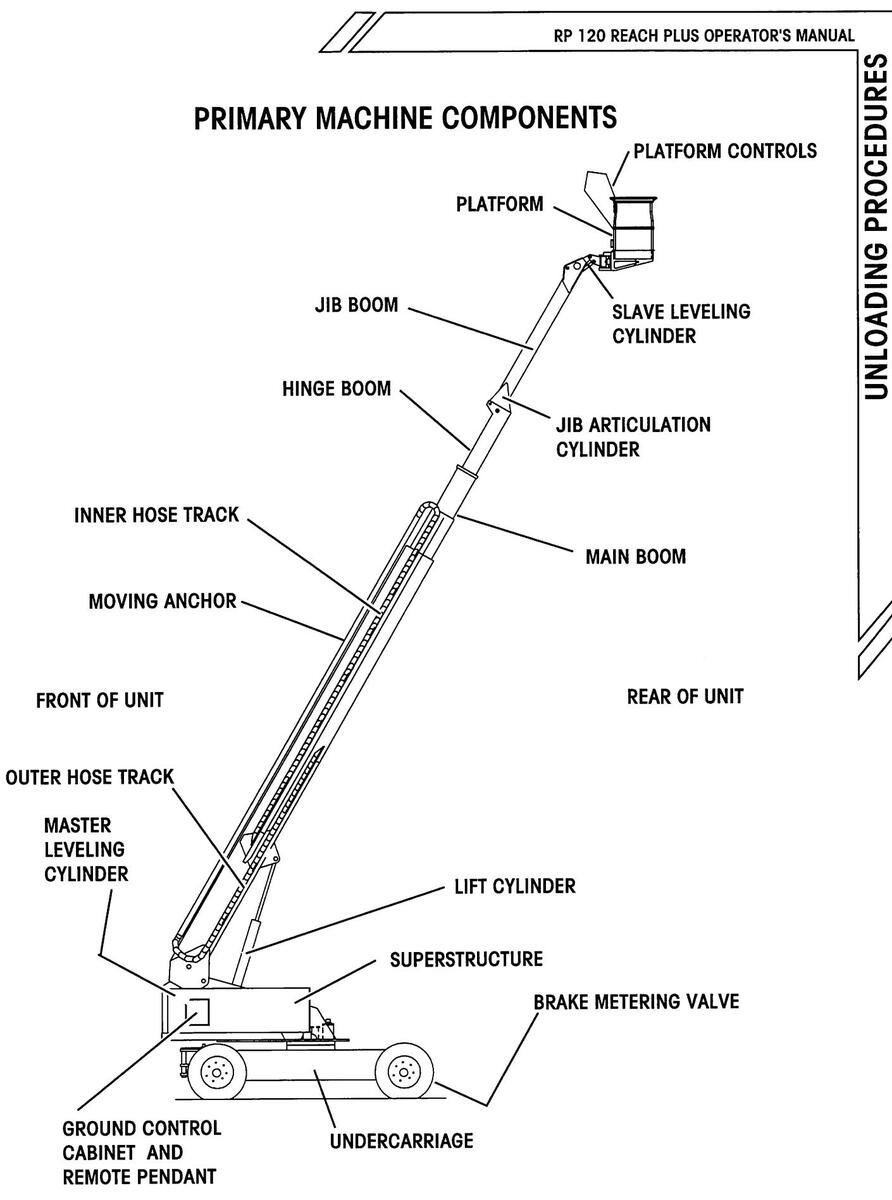
Primary Machine Components |
. 2-3
. 2-7 |
|---|---|
| Ground Controls | . 2-8 |
| 2-12 | |
| Piallorin Conirois | 2-10 |
| Graphic Display | 2-24 |
| Sidii-up Piocedules | າ າຣ |
| Snill Checks | 2-20 |
| Muchine Siun-up | 2-27 |
| Axie Exicitia Procedule | 2-20 |
| Biouria Operation and Checks | 2-01 |
| Operation | 2-40 |
| Cold Weather Operation | 2-19 |
| Driving and Steering | 2-43 |
| Braking | 2-50 |
| Boom Superstructure and Diatform | 2-50 |
| 2-57 | |
| Dual Fuel Engine Operation | 2.52 |
| Diesel Engine Operation | 2-53 |
| Shut-down Procedures | 2-54 |
| Transporting The Unit | 201 |
| Towing Procedures | 2-55 |
| Truck or Trailer Transport | |
| Boom in STOW- N -GO ™ Mode | 2-56 |
| Boom in Conventional Mode | 2-61 |
| Emergency System and Procedures | |
| Emergency Electrical Pump | 2-63 |
| Unpowered Emergency Movement | 2-64 |
| Emergency Lowering | 2-65 |
TABLE OF CONTENTS

TABLE OF CONTENTS (CONTINUED)
MAINTENANCE
|
General Maintenance Tips
Shift Operational Checklist Weekly Operational Checklist Monthly Operational Checklist |
3-3
3-4 3-7 3-9 .3-11 |
|---|---|
| Troubleshooting | |
| What to check if unit will not start: | 3-13 |
| What to check if functions will not operate: | 3-13 |
| Lubrication Chart | 3-14 |
APPENDIX
| oplicable Standards and Regulations | A-3 |
|---|---|
| NSI/SIA A92.5 - 1992 (Partial) | A-5 |
| 5. Responsibilities of Dealers | A-5 |
| 6. Responsibilities of Owners | A-7 |
| 7. Responsibilities of Users | A-10 |
| 8. Responsibilities of Operators | A-16 |
| 9. Responsibilities of Lessors | A-20 |
| 10. Responsibilities of Lessees | A-21 |
INDEX
Simon Aerials "High Five" Limited Warranty Transfer of Ownership Notice (Business Reply Cards) Catalog Comment Card (Business Reply Cards)
TABLE OF CONTENTS
NTRODUCTION
INTRODUCTION
This Operator's Manual has been designed to provide you with the instructions needed to properly and safely operate your Simon RP 120 Reach Plus Self-Propelled Aerial Work Platform featuring Electro-proportional controls.

THIS OPERATOR'S MANUAL MUST BE READ AND UNDERSTOOD PRIOR TO OPERATING YOUR SIMON SELF-PROPELLED AERIAL WORK PLATFORM.
OPERATORS MUST BE AWARE OF AND COMPLY WITH ALL MANUFAC-TURER'S INSTRUCTIONS AND APPLICABLE OSHA/ANSI SAFETY GUIDE-LINES.
FAILURE TO COMPLY WITH MANUFACTURER'S INSTRUCTIONS AND OSHA/ANSI SAFETY GUIDELINES WILL RESULT IN SERIOUS INJURY OR DEATH.
Your Simon RP 120 has been designed and built to provide many years of safe, dependable service. To obtain the full benefit of your RP, always follow the proper operating and maintenance procedures as outlined in this manual. Only trained, authorized personnel should be allowed to operate or service this machine. Service personnel should read and study this manual in order to gain a thorough understanding of the functions of the unit prior to making any repairs.

MODIFICATIONS OF THIS MACHINE FROM THE ORIGINAL DESIGN AND SPECIFICATION WITHOUT WRITTEN PERMISSION FROM SIMON AERIALS INC. ARE STRICTLY FORBIDDEN. A MODIFICATION MAY COMPROMISE THE SAFETY OF THE MACHINE, SUBJECTING USERS TO SERIOUS INJURY OR DEATH. ANY SUCH MODIFICATION WILL VOID ANY REMAINING WARRANTY.
Simon reserves the right to change, improve, modify or expand features of its equipment at any time. Specifications, models or equipment are subject to change without notice, and without incurring any obligations to change, improve, modify or expand features of previously delivered equipment.
All Simon manuals are periodically updated to reflect changes that occur in the equipment. Please contact the factory with any questions you may have regarding your machine, or the availability of more recent manuals.
MACHINE SPECIFICATIONS
| Working Height Platform Height Horizontal Reach Boom Angle O°) |
|
|---|---|
| Platform Capacity (Unrestricted) | 500 Lbs. / 225 Kg |
| Standard |
30 In. x 60 In. x 42 In.
/
.76 M x 1.52 M x 1.07 M |
| Optional | 36 In. x 96 In. x 42 In./ |
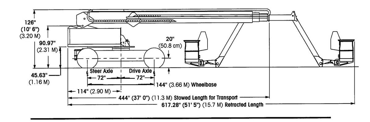
| Stowed Length (STOW- N -GO ™ Position) | 36 Ft 0 In. / 10.97 M |
| Stowed Height |
. 9 Ft 0 In./ 3.04 M
. 8 Ft 0 In./ 2.44 M |
| Machine Width: with axles extended |
11 Ft 8 In./ 3.56 M
12 Ft 0 In./ 3.66 M |
| . 11 in./ 27.9 cm | |
| Maximum Travel Speed: | 47,700 LDS./ 21,030 Kg |
| Boom Stowed (Note 1) |
2.8 MPH
/ 4.5 KPH
0.5 MPH / 0.8 KPH |
| Outside Turning Radius | 24 Ft 0 In. / 7.32 M |
|
. 180°
360° continuous, either direction |
|
| Tire Size | 15 x 22.5 (16 Ply) |
| Tire Pressure (not applicable to foam filled fires) | |
| Fuel Capacity: | |
| 30 Lbs. / 14 Kg | |
| Swing Bearing Bolt Torque |
280 Ff Lbs. / 380 Nm/ 38.7 Kg-m
220 Ff Lbs. / 298 Nm / 30.4 Kg-m 170 Ff Lbs. / 231 Nm / 23.5 Kg-m Two 12 Volt DC Batteries |
|
Engine Availability:
Standard Ford CSG-649, 110 HP (82 Kw), Liquid C Optional Ford CSG-649, 110 HP (82 Kw), Liquid C Deutz F4L912, 71 HP (53 Kw), Air Coole Perkins 4.236, 81 HP (60 Kw), Liquid co |
Cooled, Gasoline
Cooled, Dual Fuel d, Diesel Doled, Diesel |
Note 1: Weight and performance shown represent typical units, and should be used as a general guideline only. Many variables between machines can lead to significant differences in these factors. Accurate figures, when necessary for a particular application, can best be determined by testing of the specific unit.
MACHINE SPECIFICATIONS
Page iv
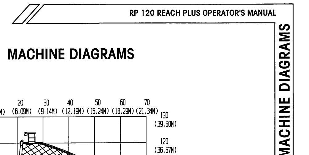
MACHINE DIAGRAMS
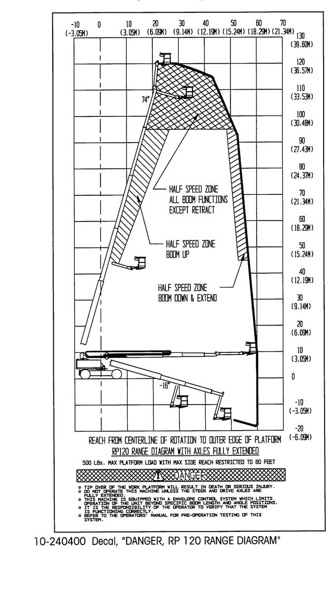
RANGE DIAGRAM


APRIL 1994
RP 120 REACH PLUS OPERATOR'S MANUAL

SECTION 1: SAFETY

Page 1- 1
Table of Contents, Section 1
SAFETY
| Cafaty Symbols | 13 |
|---|---|
| Safety Rules and Precautions | 1-4 |
| Safetý-Related Decals | |
| Safety and Control Decal Locations | 1-12 |
| Safety and Control Decal Identification | 1-13 |

SAFETY SYMBOLS
SAFETY SYMBOLS
This manual contains important information on the safe use of your SIMON Self-Propelled Aerial Work Platform. Your failure to read, understand and follow all safety rules, warnings and instructions will unnecessarily expose you and others to dangerous situations. For your safety and the safety of those around you, you must operate your aerial work platform as instructed in this manual.
You, the operator, are the single most important factor for safety when using any piece of equipment. Learn to operate your work platform in a safe manner.
To help you recognize important safety information, we have identified warnings and instructions that directly impact on safety with following signals:
A DANGER
"DANGER" INDICATES AN IMMINENTLY HAZARDOUS SITUATION WHICH, IF NOT AVOIDED, WILL RESULT IN DEATH OR SERIOUS INJURY. THIS SIGNAL WORD IS LIMITED TO THE MOST EXTREME SITUATIONS.
"WARNING" INDICATES A POTENTIALLY HAZARDOUS SITUATION WHICH, IF NOT AVOIDED, COULD RESULT IN DEATH OR SERIOUS INJURY.
A CAUTION
"Caution" indicates a potentially hazardous situation which, if not avoided, may result in minor or moderate injury. It is also used to alert against unsafe practices, and for property-damage-only situations.
One final note: The best method to protect yourself and others from injury or death is to use common sense. If you are unsure of any operation, don't start until you are satisfied that it is safe to proceed.
SAFETY RULES AND PRECAUTIONS
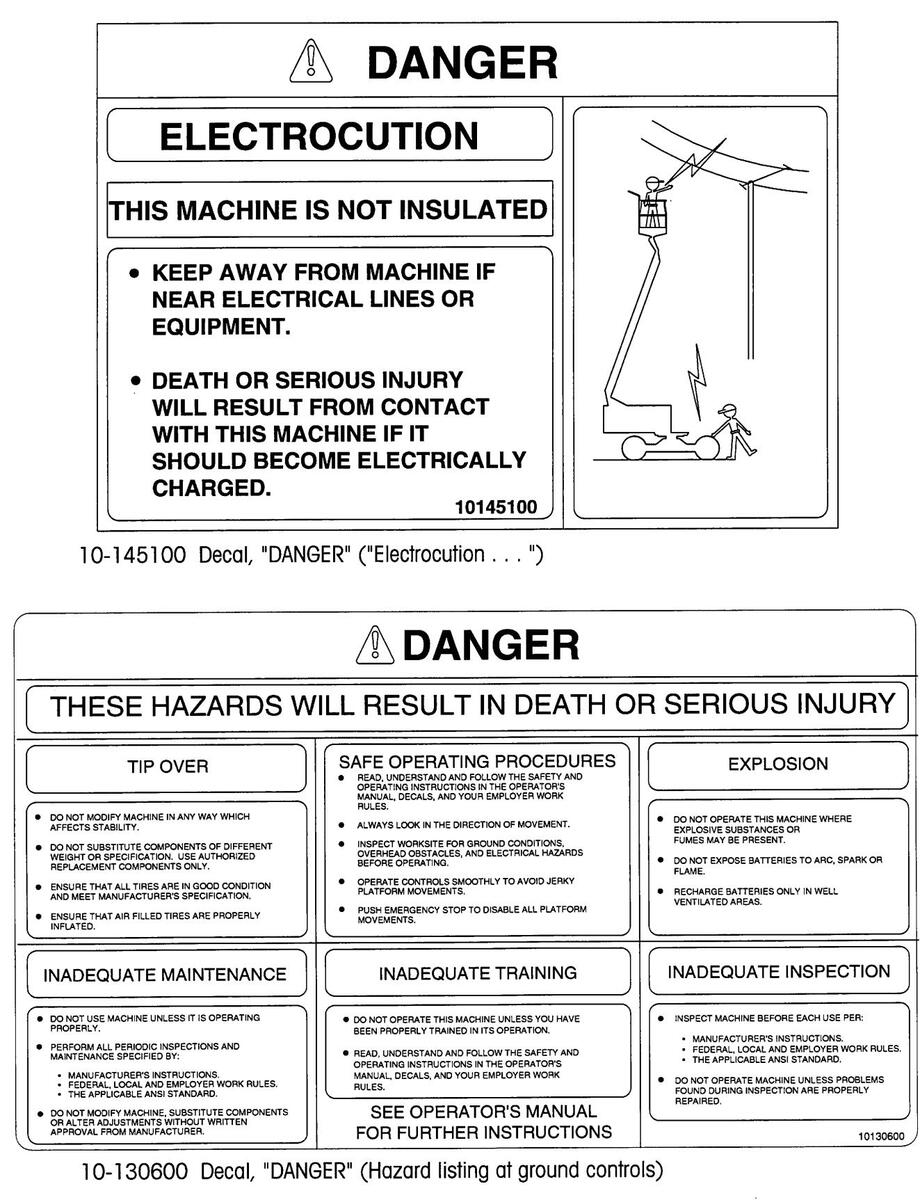
• ELECTROCUTION HAZARD!! THIS MACHINE IS NOT INSULATED!! Maintain safe clearance from electrical lines and apparatus. You must allow for machine sway (side to side movement) when elevated, and electrical line movement. This machine does not provide protection from contact with or proximity to an electrically charged conductor.
You must AVOID CONTACT between any part of the machine, or its load, and any electrical line or apparatus carrying up to 300 volts.
You must maintain a CLEARANCE OF AT LEAST 10 FEET (3.05 M) between any part of the machine, or its load, and any electrical line or apparatus carrying over 300 volts up to 50,000 volts. One foot (30.5 cm) additional clearance is required for every additional 30,000 volts.
DEATH OR SERIOUS INJURY will result from contact with, or inadequate clearance from, any electrically charged conductor.
- Read and understand all safety and control information found on the machine and in this manual before operating the unit.
- Only trained, competent personnel should operate the aerial work platform.
- Be aware of all Government and Local rules which may apply to this machine and its safe operation.
- Approved safety belts must be worn at all times when operating the unit from the platform. In addition, approved headgear and other protective equipment must be worn as required. (In the U.S.A., OSHA approved equipment is required. For other countries, the appropriate equivalent government body should be consulted.)
- NEVER fasten safety belt to an adjacent structure while on the work platform.
- Make sure that entry gate to platform is secured before operating unit from the platform.
- DO NOT block the foot pedal or any function control in the operating position.
- DO NOT exceed the platform capacity of the unit in any configuration. Review the section titled "MACHINE SPECIFICATIONS", earlier in this manual, regarding this model's capacities and dimensions.
SAFETY RULES
SAFETY RULES
SAFETY RULES AND PRECAUTIONS (CONTINUED)

- SECURE all tools and other loose items to prevent injury to persons working on or below the work platform.
- DO NOT weld on the machine unless electrical system and controller are disconnected.
- DO NOT use scaffolding, ladders or similar items to extend your reach while on the work platform.
- DO NOT attempt to climb down the boom assembly, if the unit fails while the operator's platform is raised or extended.
- Since the machine may be operated from its ground controls, precautions should be taken to prevent unauthorized personnel from operating the work platform with the ground controls while the platform is in use.
- The "UNPOWERED EMERGENCY MOVEMENT" procedure (described later in this manual) requires releasing the torque hubs, which results in there being no means to stop the unit's travel. Simon recommends using this procedure only in cases of emergency, and only for a short distance. Be on guard against unit runaway on sloping surfaces. Movement speed shall not exceed 1 M.P.H. (1.6 K.P.H.).
- DO NOT attempt to open any hydraulic line or component without first relieving all system pressures and shutting off fluid flow from the tank.
- DO NOT allow anyone to tamper with, service or operate the machine from the ground control station while personnel are on the platform, except in an emergency.
- DO NOT alter, modify or disable any safety devices or interlocks.
- DO NOT refuel the unit near sparks or open flames. Gasoline and propane vapors, and Diesel fuel fumes are highly explosive.
- DO NOT use the aerial work platform outdoors in electrical storms or in high wind situations.
- DO NOT raise the aerial work platform unless the unit is on a firm, level surface.
- ENSURE THAT the STOW- N -GO™ lock pins are in place and anchored.
SAFETY RULES AND PRECAUTIONS (CONTINUED)
- Use caution to prevent ropes, cords, hoses, etc. from becoming entangled in the unit's boom sections when being raised, lowered or repositioned.
- Ensure that the area surrounding the mobile platform is clear of personnel and equipment before: driving the unit; or raising, lowering or extending the boom; or swinging the superstructure; or, rotating or tilting the platform.
- Maintain a safe distance from overhead and ground obstacles, debris, drop-offs, holes, depressions, electrical wires and other hazards to travel.
- Limit travel speed according to conditions of the ground surface, congestion, slope, location of personnel or any other factors that could cause hazard of collision or injury to personnel.
- DO NOT sit, stand or climb on platform rails.
- DO NOT operate this machine while under the influence of any drugs or alcohol.
- DO NOT operate this machine if you are bothered by heights, seizures, or dizzy spells.
- DO NOT indulge in stunt driving or horseplay while operating this machine.
- Complete the "Operational Checklists" found in this manual (see Table of Contents) at designated intervals.
- Ensure that the machine is in "LOW" drive speed while unloading from a truck or trailer.
- Always attach the unit to a winch when loading or unloading from a truck or trailer. Simon does not recommend unassisted loading or unloading of any aerial work platform.
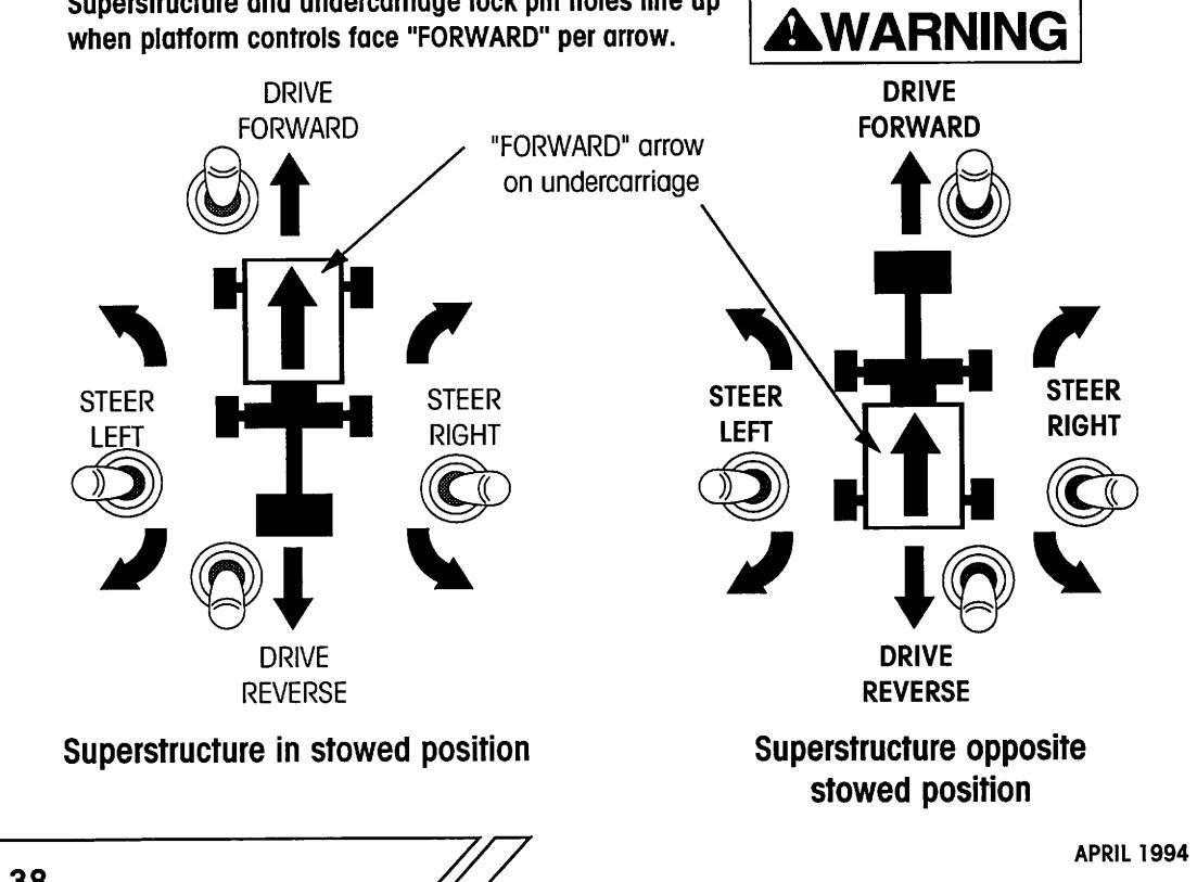
- With the superstructure swung away from the stowed position, use caution when selecting travel or steering direction. Travel and steer direction will be opposite switch or lever movement. Refer to the large "FORWARD" arrows on the undercarriage of the unit or the location of the superstructure lockpin hole for travel orientation.
SAFETY RULES
SAFETY RULES
SAFETY RULES AND PRECAUTIONS (CONTINUED)
- Check fuel system for leaks or damaged fuel lines before operating unit. If any damage is found, contact your supervisor immediately. Machine shall be removed from service until diagnosis and any necessary repairs have been completed.
- Actuation of the red "EMERGENCY STOP" button will apply brakes immediately, causing unexpected platform movement as the machine comes to a sudden stop. Brace yourself.
- Whenever disengaging the drive torque hubs or before disconnection from towing vehicle, ensure that the unit cannot roll.
- Immediately report any erratic noises, vibrations or malfunctions of the unit to supervisor. Machine shall be removed from service until diagnosis and any necessary repairs have been completed.
- Operating this equipment without all safety and control decals in place can be hazardous.
A CAUTION
- For transporting the machine, the platform must not be tied to the trailer bed in any way.
- Be sure to turn all hydraulic valves back "ON" before starting the machine, or extensive pump damage will occur.
- DO NOT exceed the maximum platform horizontal pull of 100 pounds (45.4 Kg).
- DO NOT use the boom or platform as a crane to lift oversized or hanging loads.
- DO NOT raise, extend, retract, tilt, rotate, or lower the platform into stationary objects, as this will cause damage to mechanical and hydraulic components.
- DO NOT use the platform or boom functions to push or tow the unit or another vehicle.
- Avoid sudden braking or steering, go slowly and leave more maneuvering room during cold weather operation until the machine is warm.
SAFETY-RELATED DECALS
SAFETY RELATED DECALS
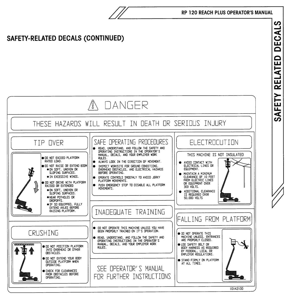
10-142100 Decal, "DANGER" (Hazard listing at platform controls)
SAFETY RELATED DECALS
Page 1-10

SAFETY RELATED DECALS
SAFETY-RELATED DECALS (CONTINUED)
WARNING! TO ASSURE FULL AXLE EXTENSION.
TO ASSURE FULL AXLE EXTENSION, ALL FOUR 2" WHITE STRIPES MUST BE FULLY EXPOSED !
10-013100 Decal, "WARNING" ("To Assure Full Axle Extension...")
AT MAX SIDE REACH
WITHIN 4 FT. OF MAX REACH
AXLES EXTENDED
10-240700 Decal, Ground Indicator Lamps
PLATFORM CAPACITY 500 LBs. (225 kg)
10-145300 Decal, Platform Capacity [18-1/4" (464 mm) wide]
PLATFORM CAPACITY 500 LBs. (225 kg)
10-148300 Decal, Platform Capacity [4-1/2" (114 mm) wide]
SAFETY AND CONTROL DECAL LOCATIONS
OPERATING THIS EQUIPMENT WITHOUT ALL SAFETY AND CONTROL DECALS IN PLACE CAN BE HAZARDOUS.

SAFETY AND CONTROL DECAL DESCRIPTIONS
|
ltem
No. |
Part Number | Description | Qty. |
|---|---|---|---|
| 1 | 10-144300 | Placard, Ground Electrical Controls | 1 |
| 2 | 10-240700 | Decal. Ground Indicator Lamps | 1 |
| 3 | 10-224900 | Placard, Remote Control Pendant | 1 |
| 4 | 10-130600 | Decal "DANGER" (Hazard listing at Ground Controls) | 1 |
| 5 | 10-012600 | Decal, "OPEN HYDRAULIC TANK VALVES " | 1 |
| 6 | 10-007200 | Decal, "DISENGAGE LOCK PIN " | 2 |
| 7 | 10-148300 | Decal, "PLATFORM CAPACITY 500 LBS (225 Kg)", | |
| [4-1/2" (114 mm) wide] | 4 | ||
| 8 | 10-145100 | Decal, "DANGER" ("Électrocution ") | 2 |
| 9 | 10-117900 | Placard, "GASOLINE ONLY" | |
| (for versions with gasoline engine) | 1 | ||
| 10-151100 | Placard, "DIESEL FUEL ONLY" | ||
| (for versions with optional Diesel engine) | 1 | ||
| 10 | 10-151300 | Placard, "HYDRAULIC FLUID ONLY " | 1 |
| 11 | 10-012900 | Decal, "FORWARD" with Arrow | 2 |
| 12 | 10-169100 | Placard, Platform Controls | 1 |
| 13 | 10-224500 | Decal, "DISPLAY CONTRAST " | 1 |
| 14 | 10-224600 a | Decal, Boom Function Speed Control | 1 |
| 15 | 10-224600 b | Decal, " ALL AXLES ARE EXTENDED" | 1 |
| 16 | 10-147400 | Decal, Platform Level and Rotate Controls | 1 |
| 17 | 10-142100 | Decal "DANGER" (Hazard listing at Platform Controls) | 1 |
| 18 | 10-013100 | Decal, "WARNING" | |
| ("To Assure Full Axle Extension ") | 2 | ||
| 19 | 2132070 | Decal, Axle Extend Instructions | 1 |
| 20 | 2132080 | Decal, "STEER OR AXLE " | 1 |
| 21 | 10-240400 | Decal, "DANGER, RP 120 RANGE DIAGRAM" | 2 |
| 22 | Call Service | Plate, Serial | 1 |
| 23 | 10-139800 | Decal, "OPERATOR'S MANUAL" | 1 |
| 24 | 10-145300 | Decal, "PLATFORM CAPACITY 500 LBS (225 Kg)", | _ |
| [18-1/4" (464 mm) wide] | 1 |
PLACARD LOCATIONS
RP 120 REACH PLUS OPERATOR'S MANUAL
OPERATION
SECTION 2: OPERATION

Table of Contents, Section 2
OPERATION
| Unloading Procedures |
2-3
2-7 |
|---|---|
| Ground Controls | 2-8 |
| Remote Control Pendant | 2-12 |
| Platform Controls | 2-16 |
| Graphic Display | 2-24 |
| Start-up Procedures | |
| Shift Checks | 2-26 |
| Machine Start-up | 2-27 |
| Axle Extend Procedure | 2-28 |
| Ground Operation and Checks | 2-31 |
| Platform Operation and Checks | 2-40 |
| Operation | |
| Cold Weather Operation | 2-49 |
| Driving and Steering | 2-00 |
| Braking | 2-00 |
| Boom, Superstructure and Platform | 2-01 |
| Gasoline Engine Operation | 2-02 |
| Dual Fuel Engine Operation | 2-52 |
| Shut down Procedures | 2-50 |
| Transporting The Unit | - 07 |
| 2-55 | |
| Truck or Trailer Transport | - 00 |
| Boom in STOW- N -GO™ Mode | 2-56 |
| Boom in Conventional Mode | 2-61 |
| Emergency System and Procedures | |
| Emergency Electrical Pump | 2-63 |
| Unpowered Emergency Movement | 2-64 |
| Emergency Lowering | 2-65 |
OPERATION
JNLOADING PROCEDURES
UNLOADING PROCEDURES
TO AVOID SERIOUS PERSONAL INJURY OR DEATH, ENSURE THAT THE MACHINE IS IN "LOW" DRIVE SPEED WHILE UNLOADING FROM A TRUCK OR TRAILER.
- 1. Inspect the outside of the unit for damage (including the underside). Inspect all hoses, boom sections and cables for chafing or shipping damage. Confirm that all wheel lug nuts and swing bearing bolts are tight (refer to specifications).
- 2. Remove the pin that locks the superstructure to the undercarriage near the swing bearing. Stow the lock pin in the location provided nearby.
- 3. Unlock and open both side compartments. Inspect all fuel, electrical and hydraulic connections for damage and security.
- 4. Connect battery cables to batteries if required. Check electrolyte level.
- 5. Open the fuel tank valve and check fuel level.
- 6. Check engine oil level, and add as required per engine manufacturer's recommendations.
- 7. Check fluid level at the sight gauge on the hydraulic tank, and add fluid as required (see Lubrication Chart). Check that shutoff valves on the hydraulic tank are open.
- 8. Close side compartment covers.
- 9. Attach the unit to a winch for the unloading procedure.
ALWAYS USE A WINCH TO ASSIST LOADING OR UNLOADING THE UNIT FROM A TRUCK OR TRAILER. CONNECT WINCH CABLE TO THE TIE DOWN LUGS ON THE UNDERCARRIAGE. UNASSISTED LOADING OR UNLOAD-ING OF ANY MOBILE PLATFORM IS NOT RECOMMENDED.
READ AND UNDERSTAND ALL SAFETY, CONTROL AND OPERATING INFORMATION FOUND ON THE MACHINE AND IN THIS MANUAL BEFORE OPERATING THE UNIT.
APRIL 1994
UNLOADING PROCEDURES
UNLOADING PROCEDURES (CONTINUED)
10. Start engine, using the ground controls.
NOTE: Refer to Start-up Procedures and Operator Controls Descriptions in this section.
After a brief warm-up period, select the "HI" engine speed. On the remote control pendant, press and hold the "PUMP" toggle switch to the "MAIN" position, but do not operate any drive or boom function. This is called "deadheading", and will lead to maximum system pressure registering on the gauge at the ground control valve assembly. Refer to the "Machine Specifications" section of this manual for the "Maximum Hydraulic Pressure" for this unit.
Select the "LOW" engine speed and allow the engine to slow to idle speed.
- 11. Remove tie downs from the platform and base of the jib boom.
- 12. Remove the two straps that wrap over the top of the undercarriage. Remove four tie down chains. Remove wheel chocks, if used.

UNLOADING PROCEDURES (CONTINUED)
- 13. Using the remote control pendant, raise the boom so that the platform will clear any obstacles as the machine is driven down the loading ramp.
- 14. Stand in front of the left front wheel (away from the direction of travel) and, using the "DRIVE" toggle in "REVERSE", carefully drive the unit off the truck or trailer with the assistance of a winch. The brakes are automatically released for driving, and will automatically apply when the unit stops.
- 15. Remove the grip end of the pull chain from its stored position on the left side of the main boom, and let it hang free. The boom stowage lock pin has a 5 Ft (1.5 M) long pull chain attached for ease of use. Remove boom lock pins from stowed position, and let hang.
- 16. Raise main boom to horizontal and lower jib boom until it is 60° below the main boom.

Swing Jib Around to Operational Mode.
- 17. Pull the boom stowage lock pin chain to unlock the jib boom. Swing jib and platform around so that the hinge boom aligns with the main boom (see "Operational Mode" illustration, next page).
- 18. Lower the main boom so the boom support stand is slightly off the ground. Pull the pin holding the boom support stand strut to the boom support column, and swing boom support column up. Pin the strut to the underside of base boom.

Raise Boom Support Stand.
UNLOADING PROCEDURES (CONTINUED)
19. Align hinge and main boom holes by moving the jib boom, and insert boom lock pins to secure hinge boom to main boom.
If hinge and main boom holes do not line up, slightly lower main boom onto ground to apply pressure on jib boom.
20. Secure hinge boom to main boom with both boom lock pins and hairpin clips.
21. Turn engine off.

UNLOADING PROCEDURES
Left Hand Side.
OPERATOR CONTROLS
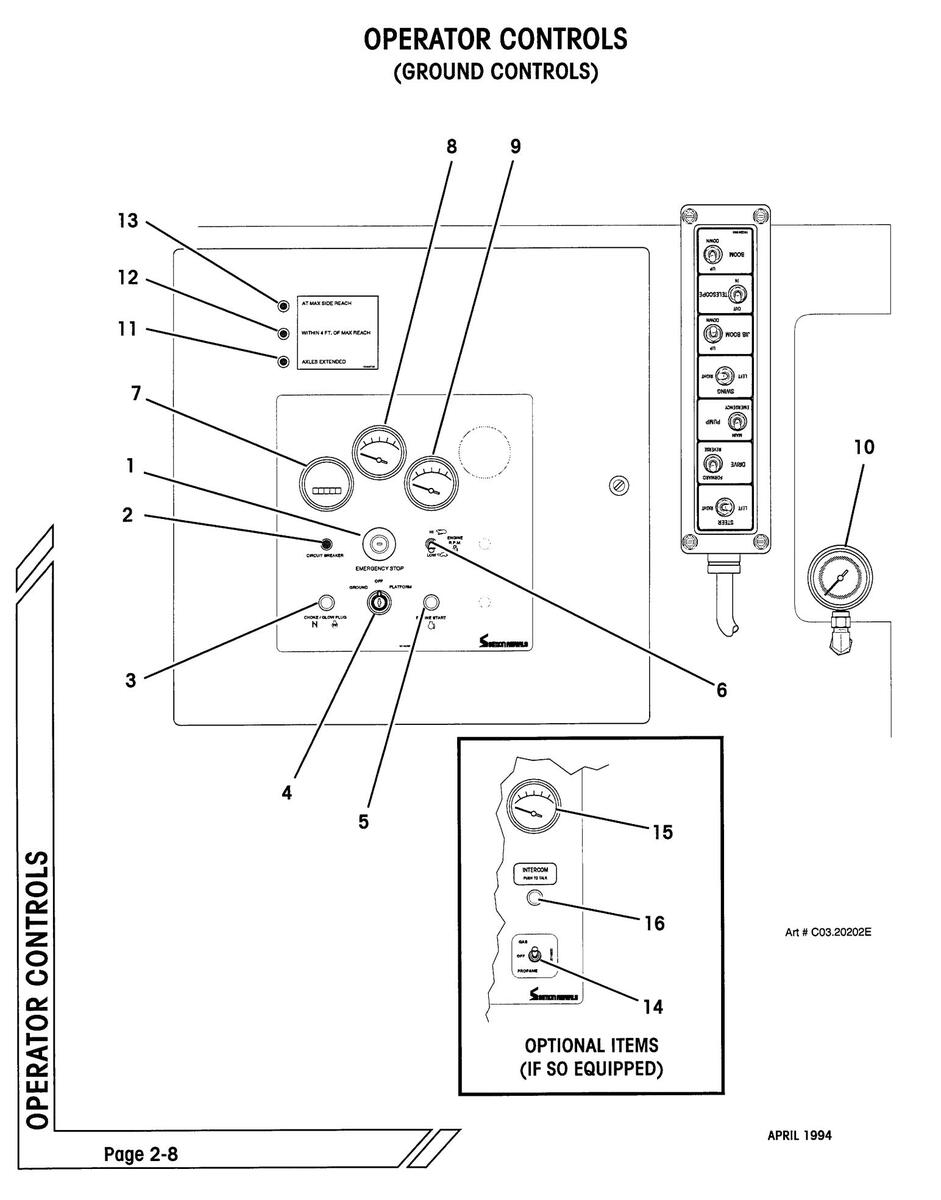
OPERATOR CONTROLS DESCRIPTION (GROUND CONTROL)
| ltem | Control | Location | Description |
|---|---|---|---|
| 1. |
Emergency Stop
Button |
On Ground
Electrical Panel |
Used to stop all functions in an emergency. Push for emergency stop. Pull or rotate clockwise to reset, depending on style used. |
| 2. | Circuit Breaker |
On Ground
Electrical Panel |
Pops out when the 12 Volt electrical circuit is over-
loaded. Push in to reset. |
| 3. |
Choke/
Glow Plug Button |
On Ground
Electrical Panel |
Choke button for gas or dual fuel engines. Press and hold while starting a cold engine. |
| Glow plug button for some Diesels. Press and hold (if so equipped) to preheat combustion chamber before starting a cold engine. | |||
| 4. |
Main Power Key
Switch |
On Ground
Electrical Panel |
Three position main power "On/ Off" switch. Straight up position is "OFF". |
|
Turn key left (counterclockwise) one position to turn
power "ON" for ground control operation. Turn key right (clockwise) one position to turn power "ON" for plat- form control operation. |
|||
| With key switch "OFF", the key may be removed to prevent unauthorized operation. | |||
| 5. |
Engine Start
Button |
On Ground
Electrical Panel |
Press push button to engage engine starter. Release
button immediately upon engine start. If the engine does not start within 10 seconds, the main power key switch must be turned off and then on again to start. |
| NOTE: Main power key switch must be in "GROUND" position. | |||
| 6. |
Engine RPM
(Throttle) Switch |
On Ground
Electrical Panel |
Flip toggle down for "LO" (idle) engine speed. Flip toggle up for "HI" engine speed. |
| IMPORTANT: Engine should not be in "LO" speed while operating any hydraulic functions. | |||
| 7. | Hour Meter |
On Ground
Electrical Panel |
Indicates total elapsed time that the engine has been operated in hours and tenths. |

OPERATOR CONTROLS
OPERATOR CONTROLS DESCRIPTION (GROUND CONTROLS, CONTINUED)
| ltem | Control | Location | Description |
|---|---|---|---|
| 8. | Volt Meter |
On Ground
Electrical Panel |
Indicates electrical system voltage. |
| 9. |
Engine Oil Pres-
sure Gauge |
On Ground
Electrical Panel |
Indicates engine oil pressure. |
| 10. |
Hydraulic Fluid
Pressure Gauge |
Beneath Ground
Valves |
Indicates hydraulic fluid pressure. |
| 11. |
L.E.D. Indicator
(Green) |
On Ground
Electrical Panel |
When lit, indicates that front and rear axles are fully extended, and full range of boom operation is possible. |
| 12. |
L.E.D. Indicator
(Yellow) |
On Ground
Electrical Panel |
When lit, indicates that boom is within 4 Feet (1.22 M) of maximum outreach. Envelope Control System (ECS) will not allow boom functions (Main boom extend or lower, jib boom raise) to extend beyond the perimeter of the performance envelope. |
| 13. |
L.E.D. Indicator
(Red) |
On Ground
Electrical Panel |
When lit, indicates that boom has reached the perim-
eter of the performance envelope. |
| 14. |
Gas/ Off/ Propane
Switch (Optional) |
On Ground
Electrical Panel |
Flip toggle up to use gasoline, down to use propane. In "OFF" position, the engine is not supplied with fuel. |
| 15. |
Engine Coolant
Temperature Gauge (Optional) |
On Ground
Electrical Panel |
Indicates Engine coolant temperature. |
| 16. |
Intercom "Push-
To-Talk" Button (Optional) |
On Ground
Electrical Panel |
Press and hold to talk to operator in platform. Micro-
phone is located in speaker above electrical panel. |
| 17. |
Axle Extend Knob
(Not shown) |
On side of
undercarriage, behind left rear wheel |
Pull knob out to select Axle Extend function. Refer to Axle Extend Procedure in this section. |
| 18. |
Steer Wander
Control Valve (Not shown) |
Near Ground
Electrical Panel |
Available with optional tow package only. Pull valve knob out to allow the steering to be free wheeling Push valve knob in to engage steering. |
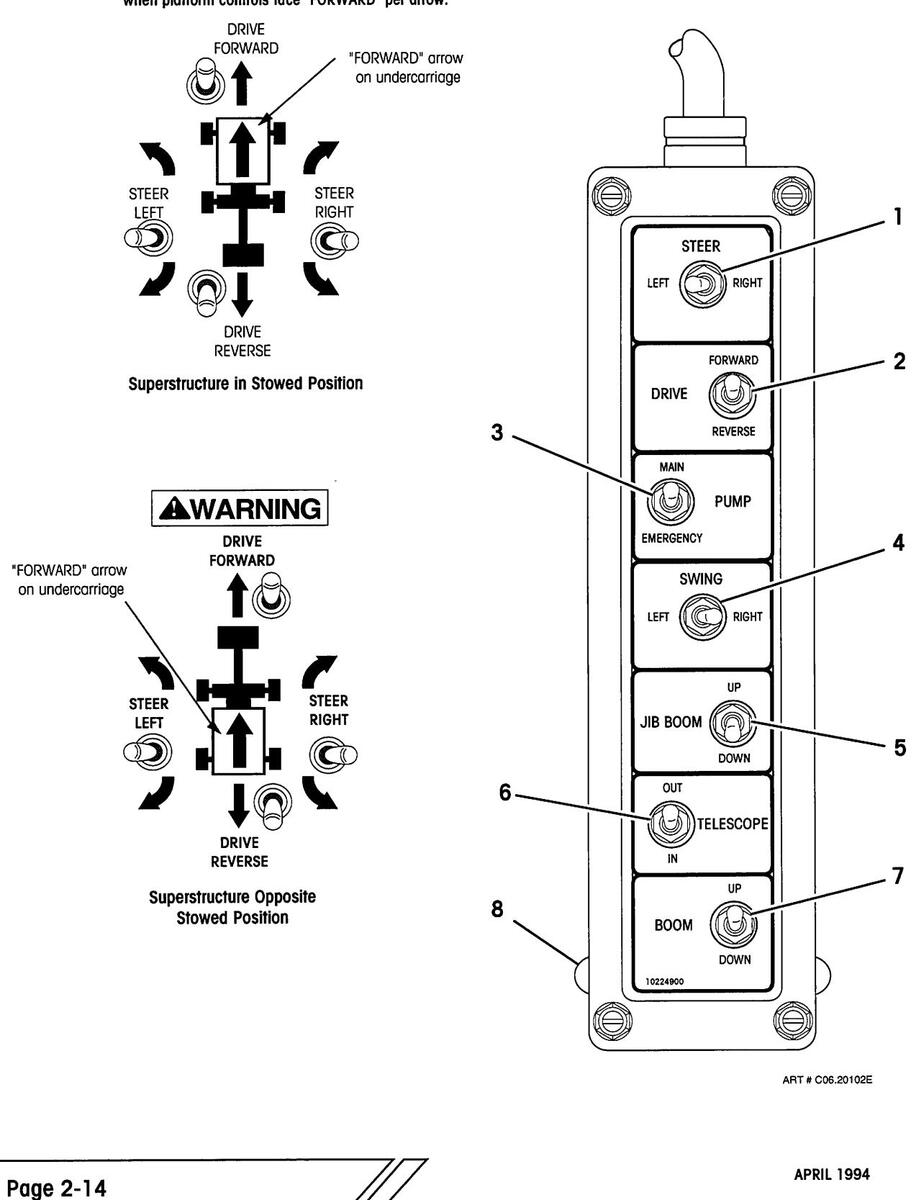
OPERATOR CONTROLS (REMOTE CONTROL PENDANT)
Control operation direction shown here in relation to "FORWARD" arrow on undercarriage. Superstructure and undercarriage lock pin holes line up when platform controls face "FORWARD" per arrow.

OPERATOR CONTROLS
DPERATOR CONTROLS

| ltem | Control | Location | Description |
|---|---|---|---|
| 1. |
Steer Toggle
Switch |
On Remote
Control Pendant |
Push to left and hold to turn steer wheels to left, right to turn to right. To straighten wheels, push and hold switch in opposite direction. |
WITH THE PLATFORM OVER THE STEERING WHEELS, USE CAUTION WHEN SELECTING THE STEERING DIRECTION. STEER DIRECTION WILL BE OPPOSITE SWITCH MOVEMENT. SEE DIAGRAM, FACING PAGE.
During axle extend procedure, the steer switch is used to extend and retract the axles.
2. Drive (Propel) On Remote Control Pendant On Remote Control Pendant On Remote Control Pendant On Remote Control Pendant On Remote Control Pendant On Remote Control Pendant On Remote Control Pendant On Remote Control Pendant On Remote Control Pendant On Remote Control Pendant On Remote Control Pendant On Remote Control Pendant On Remote Control Pendant On Remote Control Pendant On Remote Control Pendant On Remote Control Pendant On Remote Control Pendant On Remote Control Pendant On Remote Control Pendant On Remote Control Pendant On Remote Control Pendant On Remote Control Pendant On Remote Control Pendant On Remote Control Pendant On Remote Control Pendant On Remote Control Pendant On Remote Control Pendant On Remote Control Pendant On Remote Control Pendant On Remote Control Pendant On Remote Control Pendant On Remote Control Pendant On Remote Control Pendant On Remote Control Pendant On Remote Control Pendant On Remote Control Pendant On Remote Control Pendant On Remote Control Pendant On Remote Control Pendant On Remote Control Pendant On Remote Control Pendant On Remote Control Pendant On Remote Control Pendant On Remote Control Pendant On Remote Control Pendant On Remote Control Pendant On Remote Control Pendant On Remote Control Pendant On Remote Control Pendant On Remote Control Pendant On Remote Control Pendant On Remote Control Pendant On Remote Control Pendant On Remote Control Pendant On Remote Control Pendant On Remote Control Pendant On Remote Control Pendant On Remote Control Pendant On Remote Control Pendant On Remote Control Pendant On Remote Control Pendant On Remote Control Pendant On Remote Control Pendant On Remote Control Pendant On Remote Control Pendant On Remote Control Pendant On Remote Control Pendant On Remote Control Pendant On Remote Control Pendant On Remote Control Pendant On Remote Control Pendant On Remote Control Pendant On Remote Control Pendant On Remote Control Pendant On Remote Control Pendant On Remote Control Pendant On Remote Control Pendant On Remote Control Pendant

WHEN THE PLATFORM IS SWUNG OVER THE STEER-ING WHEELS, USE CAUTION WHEN SELECTING THE TRAVEL DIRECTION. TRAVEL DIRECTION WILL BE OPPOSITE SWITCH MOVEMENT. SEE DIAGRAM, FACING PAGE.
3. Pump Selector On Remote Push up and hold to activate main hydraulic pump, Toggle Switch Control Pendant enabling operation of any of the hydraulic functions (drive, steer, or boom movement) from the ground.
On Remote Push down and hold to activate battery powered emergency hydraulic pump, allowing operation of hydraulic functions (drive, steer or boom movement) from the ground should the engine powered hydraulic pump be disabled.
OPERATOR CONTROLS
OPERATOR CONTROLS (REMOTE CONTROL PENDANT)
Control operation direction shown here in relation to "FORWARD" arrow on undercarriage. Superstructure and undercarriage lock pin holes line up when platform controls face "FORWARD" per arrow.
OPERATOR CONTROLS

| tem | Control | Description | |
|---|---|---|---|
| 4. |
Swing Toggle
Switch |
On Remote
Control Pendant |
Push and hold left to swing the superstructure left (clockwise) and to the right to swing the superstructure right (counterclockwise). |
| 5. |
Jib Boom Toggle
Switch |
On Remote
Control Pendant |
Push up and hold to raise (hoist) jib boom, and down to lower jib boom. |
| 6. |
Boom Telescope
Toggle Switch |
On Remote
Control Pendant |
Push up and hold to extend main boom, and down to retract main boom. |
| 7. |
Main Boom
Toggle Switch |
On Remote
Control Pendant |
Push up and hold to raise (hoist) main boom, and down to lower main boom. |
| 8. |
Pendant Hanger
Knobs |
Back of Remote
Control Pendant |
Used to hang Remote Control Pendant on the panel to the right of the Ground Control Box when not in use. |

Page 2-16
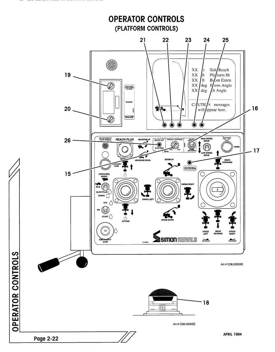
OPERATOR CONTROLS

(PLATFORM CONTROLS)
| item | Control | Location | Description |
|---|---|---|---|
| 1. |
Emergency Stop
Button |
On Platform
Console |
Used to stop all functions in an emergency. Push for emergency stop. Pull or rotate clockwise to reset, depending on style used. |
| 2. |
Off/ On/ Start
Switch |
On Platform
Console |
Three position toggle switch. Up is "OFF". Move to center position to turn ignition "ON", down to engage starter. If the engine does not start within 10 seconds, switch must be turned off and then on again to start. |
| IMPORTANT: Engine will not start with foot pedal depressed. | |||
|
On Platform
Console |
For gasoline engines, press toggle to down position and hold when starting a cold engine. | |
| For some Diesel engines (equipped with glow plugs), press and hold to preheat combustion chamber before starting a cold engine. | |||
| Flip toggle to center position for low (idle) engine speed, up for high (operating) engine speed | |||
| IMPORTANT: Machine should not be in low (idle) speed while operating any hydraulic functions. | |||
| 4. |
Auxiliary Pump
Push Button |
On Platform
Console |
Press and hold to activate battery powered emergency hydraulic pump, allowing operation of drive, steer, boom or platform movement should the engine powered hydraulic pump be disabled. |
| 5. |
Engine Warning
Indicator |
On Platform
Console |
Red light that illuminates to indicate low engine oil pressure or high engine coolant temperature. Engine will shut down automatically if condition does not correct itself in approximately 10 seconds. |

Page 2-18
OPERATOR CONTROLS
OPERATOR CONTROLS DESCRIPTION (PLATFORM CONTROLS, CONTINUED)
| ltem | Control | Location | Description |
|---|---|---|---|
| 6. |
Boom Telescope
Lever |
On Platform
Console |
Lever controls the boom telescope function. Pull back to extend boom. Push forward to retract boom. Boom speed will be proportional to handle movement. |
| 7. |
Main Boom Lift
and Swing Control Lever |
On Platform
Console |
Push lever forward to raise main boom. Pull lever back to lower main boom. Boom speed will be proportional to handle movement. |
|
Push lever to right to swing superstructure to right
(counterclockwise). Push lever to left to swing left (clockwise). Superstructure can rotate 360° continu- ously in either direction. Swing speed will be propor- tional to handle movement. |
|||
| 8. |
Platform Rotate
Lever |
On Platform
Console |
Operate lever in direction of desired platform rotation.
Pull lever counterclockwise to rotate the platform coun- terclockwise. Push lever clockwise to rotate platform clockwise. |
| 9. |
Platform Leveling
Lever |
On Platform
Console |
Push lever forward to tilt platform forward. Pull lever back to tilt platform back. |
| 10. |
"Reach Plus"
Jib Boom Lever |
On Platform
Console |
Push lever forward to raise jib boom. Pull lever back to lower jib boom. Boom speed will be proportional to handle movement. |
| 11. |
Drive Control
Lever |
On Platform
Console |
Controls forward and reverse machine travel at a speed proportional to handle movement. |

WHEN PLATFORM IS SWUNG OVER THE STEERING WHEELS, USE CAUTION WHEN SELECTING THE TRAVEL DIRECTION.
TRAVEL DIRECTION WILL BE OPPOSITE DRIVE CONTROL LEVER MOVEMENT.
SEE DIAGRAM, FACING PAGE.

Page 2-20
FROLS

| ltem | Control | Location | Description | 00 | |||
|---|---|---|---|---|---|---|---|
| 12. | Steer Switch |
On end of Drive
Control Lever |
Move switch left and hold to turn steer wheels to left, and right to turn steer wheels to right. To straighten wheels, push and hold in opposite direction. | RATOR | |||
| OPE | |||||||
|
WHEN PLATFORM IS SWUNG OVER THE
STEERING WHEELS, USE CAUTION WHEN SELECTING THE STEERING DIRECTION. |
|||||||
|
STEERING DIRECTION WILL BE OPPOSITE
STEER SWITCH MOVEMENT. |
|||||||
| SEE DIAGRAM, FACING PAGE. | |||||||
| During axle extend procedure, the steer switch is used to extend and retract the axles. | |||||||
| 13. |
Drive Speed
Switch |
On Platform
Console |
Press switch up for "HIGH" machine travel speed, down
for "LOW" speed. "High" or "Iow" speed travel are available only while main boom is below horizontal and extended less than 9 feet (2.7 Meters). With main boom raised or extended, machine travels only at slowest "creep" speed. |
||||
14. Horn Button On Platform Press button to sound warning horn. Console
OPERATOR CONTROLS

| ltem | Control | Location | Description |
|---|---|---|---|
| 15. |
Display Screen
Contrast Knob |
On Platform
Console |
Allows adjustment of the brightness and contrast of the image on the display screen. |
| 16. |
Boom Speed
Selector (Opt.) |
On Platform
Console |
Allows selection of "HIGH" or "LOW" boom raise, lower, extend or retract speed. |
| 17. |
Axle Extend
L.E.D. (Green) |
On Platform
Console |
When lit, indicates that front and rear axles are fully extended, and full range of boom operation is possible. |
| 18. | Foot Pedal Switch |
On Platform
Floor |
Must be depressed to activate main hydraulic pump,
allowing operation of any hydraulic function (drive, steer, boom or platform movement) from the platform. Depress pedal before selecting function. |
| 19. |
"Talk" Volume
Control Switch |
On Intercom
(Optional) |
Allows adjustment of the volume for "SEND" intercom function. |
| 20. |
"Listen" Volume
Control Switch |
On Intercom
(Optional) |
Allows adjustment of the volume for "RECEIVE" inter-
com function. |
| 21. |
"Power" L.E.D.
Indicator |
Below Display
Screen |
When lit, indicates that computerized Envelope Control System (ECS) is on. |
| 22. |
"OK" L.E.D.
Indicator |
Below Display
Screen |
When lit, indicates that Envelope Control System (ECS) has performed self tests and is functioning properly. |
| 23. |
"Fail" L.E.D.
Indicator |
Below Display
Screen |
When lit, indicates a failure in the Envelope Control System (ECS). |
| 24. |
"Warning" L.E.D.
Indicator |
Below Display
Screen |
When lit, indicates that boom is within 4 Ft (1.22 M) of maximum outreach. |
| 25. |
"Stop" L.E.D.
Indicator |
Below Display
Screen |
When lit, indicates that boom has reached maximum extension. Further outreach is blocked. |
| 26. |
L.E.D. Indicator
(Green) |
On Platform
Console |
When lit, indicates that Envelope Control System (ECS) backup computer is functioning properly. |
| 27. |
Light Switches
(Optional) |
On Lights
(Not Shown) |
Flip switch to turn head lights on and off. Lights are
powered by gel cell battery located on the right side of platform console. Lights blink when battery is close to discharge (approximately 45 minutes). |
OPERATOR CONTROLS
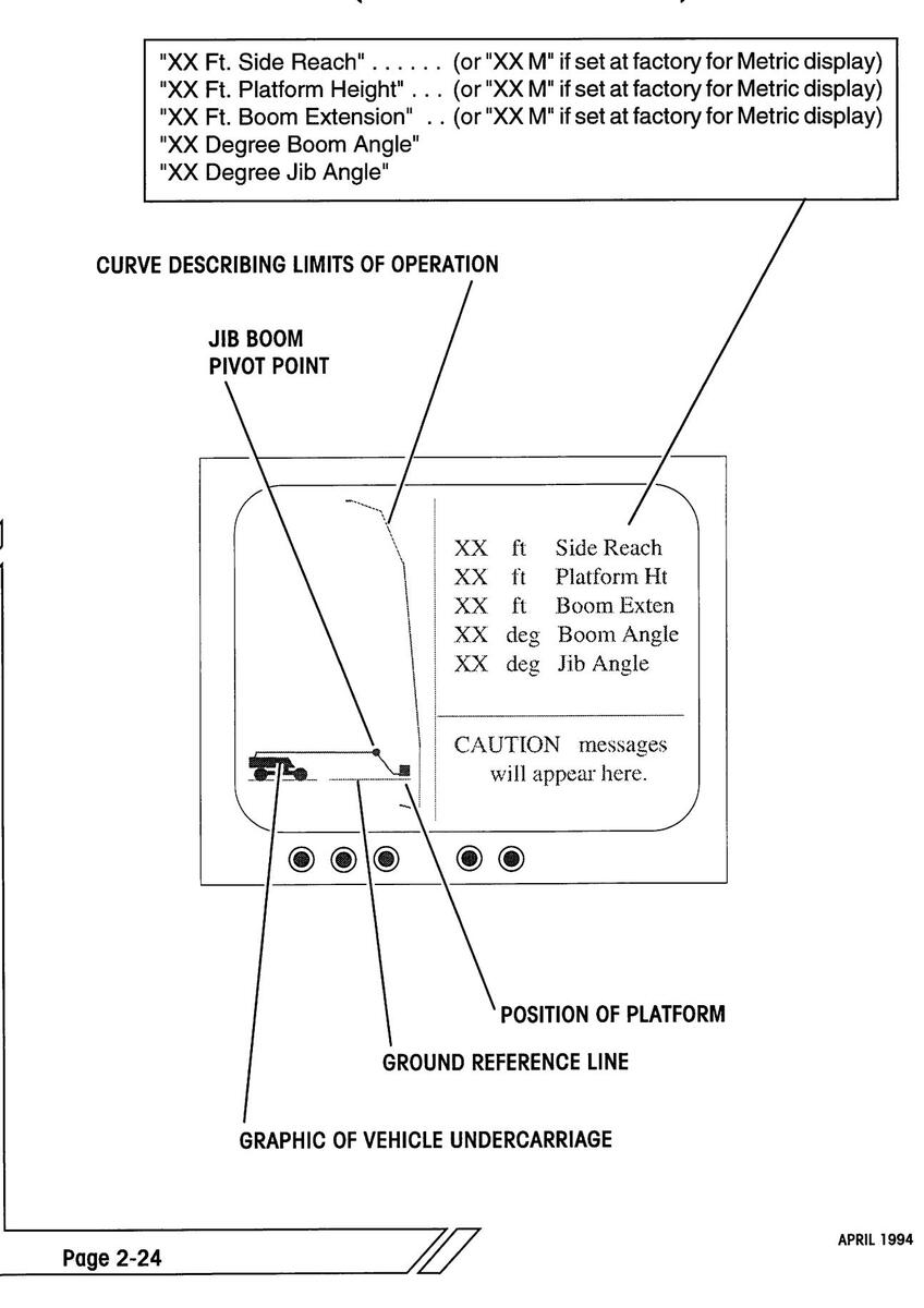
GRAPHIC DISPLAY DESCRIPTION (ENVELOPE CONTROL SYSTEM)
DPERATOR CONTROLS
GRAPHIC DISPLAY DESCRIPTION (ENVELOPE CONTROL SYSTEM)
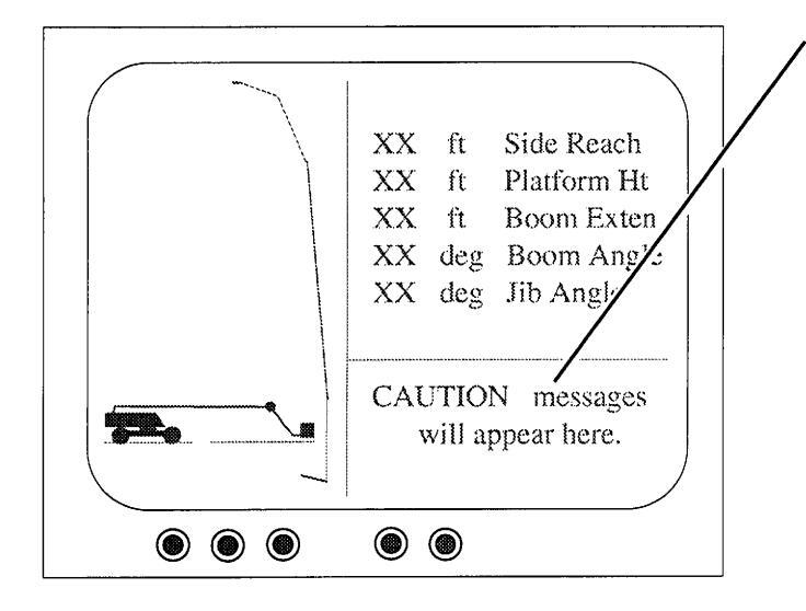
"Jib Function Only" indicates that the main boom tip has reached the boom side reach limit. The platform can still be extended out further, but only by using the jib boom control.
"Low Speed Boom Down" indicates that, for safety reasons, the ECS (Envelope Control System) has reduced the boom lowering speed.
"Caution: Approaching side reach limit" indicates that the platform is within 4 Ft (1.22 M) of maximum outreach.
"Caution: Maximum side reach" indicates that platform has reached maximum extension. Further outreach is blocked.
"Caution: Chassis Tilted" indicates that chassis (undercarriage) of machine has exceeded the 5 degree maximum angle for safe operation. MACHINE CAN TIP OVER!
- Immediately stop all functions.
- Evaluate the situation, then
- Calmly and carefully remedy the problem causing the excessive chassis angle.
Driving in the opposite direction to straighten the chassis angle or retracting the main boom will normally eliminate the danger. HOWEVER, reversing the function that prompted the warning MAY NOT be the safest action. PROCEED WITH EXTREME CAUTION.
NOTE: For safety reasons, the boom "EXTEND" and boom "DOWN" functions are disabled as long as the "Chassis Tilted" caution is displayed.
SHIFT CHECKS
Before the Simon RP 120 Work Platform is put into use each shift, the following checks should be completed to make sure that the machine is safe and in good condition.
Refer to check lists at back of this manual for periodic maintenance requirements and additional procedures for severe duty applications:
- _____ Visually inspect all machine components, i.e. missing parts, torn or loose hoses, hydraulic fluid leaks, torn or disconnected wires, flat or damaged tires, etc. Both compartment doors can be opened to inspect components inside.
- Check engine oil and fuel levels.
- Check engine coolant level (on liquid cooled units).
- ____ Check battery electrolyte level and connections.
- Check hydraulic fluid level with booms fully retracted and lowered.
- ____ Check that all shutoff valves on the hydraulic tank are open. When open, valve handles will be parallel with the length of the valve.
The shutoff values on the hydraulic tank must be left open at all times, except during repairs or transport. If one or more of these values are closed when the unit is running, extensive pump damage will occur.
- ____ Check wheel lug nuts for tightness. Check tire pressure (see Specification page).
-
____ Check hoses and cables for worn areas.
- ____ Check hose carrier to make sure that it is not bent or sagging.
- _____ Inspect safety belt connections and check for worn areas on the belts.
- ____ Check platform rails and safety gate latch for damage.
- ____ Check pivot pins for security.
- ____ Check that all warning and instructional labels are legible and secure.
Page 2-26
START-UP PROCEDURES
APRIL 1994
MACHINE START-UP
ALL OPERATORS MUST THOROUGHLY READ AND UNDERSTAND THE "SAFETY RULES AND PRECAUTIONS" SECTION OF THIS MANUAL PRIOR TO OPERATING THE MACHINE.
A COMPLETE VISUAL INSPECTION OF THE MACHINE MUST BE PER-FORMED PRIOR TO OPERATIONAL CHECKS.
- Disengage lock pin before swinging the superstructure.
- Ensure that emergency stop buttons on ground control panel and platform control console are disenaaged. Pull out or twist to reset, depending on style.
- Ensure that engine RPM toggle switch is set to "LOW".
- Turn the main power key switch to the "GROUND" position to energize the electrical system.
- Push down on each of the three fastened corners of the tilt alarm located behind the electrical box. The alarm should sound as each corner is pressed beyond 5 degrees.
- While starting a cold engine, for gasoline or dual fuel engines, press choke button, or
for some optional Diesel engines, press glow plug button, and hold it there for 30 to 45 seconds prior to engaging starter motor.
- Press and hold engine start button to start engine. After a brief warm-up period, select the "HI" engine speed setting with the engine R.P.M. toggle switch.
- On the remote control pendant, press and hold the "PUMP" toggle to the "MAIN" position, but do not operate any drive or boom function. This is called "deadheading", and will lead to maximum compensator setting of the pump system pressure registering on the gauge at the ground control valve bank assembly. Refer to the "Machine Specifications" section of this manual for the "Maximum Hydraulic Pressure" for this unit.
- Check that the hydraulic pressure is as stated in the "Machine Specifications" of this manual.
AXLE EXTEND PROCEDURE
The RP 120 Aerial Work Platform is equipped with extendable front and rear axles.
Interlocks at each axle will prevent the boom from extending beyond a short distance or raising above horizontal unless the axles have been extended.
THE RP 120 MODEL IS EQUIPPED WITH INTERLOCKS WHICH LIMIT OPERATION OF THE UNIT WITH RETRACTED AXLES BEYOND SPECIFIC BOOM LENGTH AND ANGLE RANGES.
IT IS THE RESPONSIBILITY OF THE OPERATOR TO VERIFY THAT ALL OF THESE INTERLOCKS ARE FUNCTIONING CORRECTLY.
FAILURE TO FOLLOW THESE INSTRUCTIONS MAY RESULT IN DEATH OR SERIOUS INJURY.
To test for proper interlock operation:
• Press and hold the "PUMP" toggle on the remote pendant to the "MAIN" position.
IMPORTANT: The "PUMP" toggle must be pressed to operate any of the machine functions.
- Press and hold the main "BOOM" toggle switch on the remote control pendant to the "UP" position to raise the main boom. Boom should stop when it reaches the horizontal position. If it does not, the interlocks are not functioning properly, and must be repaired.
- Release the "BOOM" toggle.
- Press and hold the "TELESCOPE" toggle switch on the remote control pendant to the "OUT" position to extend the boom. Boom should stop after extending a short distance. If it does not, the interlocks are not functioning properly, and must be repaired.
- Retract the boom fully. Release the "TELESCOPE" toggle.
Note: do not lower the boom at this point.
To extend the axles, make sure unit is on a firm, level surface:
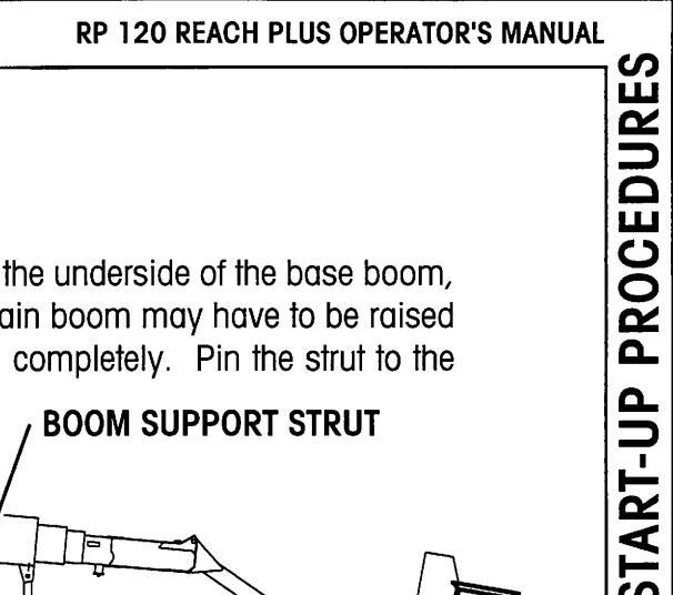
AXLE EXTEND PROCEDURE (CONTINUED)
Pull the pin holding the boom support stand strut to the underside of the base boom, and swing the boom support column down. The main boom may have to be raised slightly to allow the support column to swing down completely. Pin the strut to the column.

Raise Boom Support Stand.

SUPERSTRUCTURE WILL BE ROTATED 180 DEGREES. BE SURE BOOM TRAVEL AREA IS CLEAR OF OBSTRUCTIONS.
IMPORTANT: Axle extend procedure using ground controls is described below. Boom should not be in "STOW-N-GO" mode. Extend procedure using platform controls is not recommended.
- Locate the steer/ axle extend selector valve handle, located on the side of the undercarriage behind the left steer wheel. Select "AXLE EXTEND" by pulling handle out.
- Switch the engine "R.P.M." switch on the ground electrical panel to "HIGH". Press and hold the "PUMP" toggle on the remote pendant to the "MAIN" position.
IMPORTANT: The "PUMP" toggle must be pressed to operate any of the machine functions.
- Operate the swing function by pressing the "SWING" toggle right to swing right, or left to swing left. Swing the boom 180 degrees over to the steer axle end of the unit. Release the "SWING" toggle.
- Lower the boom by pressing the "BOOM" toggle to the "DOWN" position. Lower the boom enough to raise the steer tires off of the ground. Release the boom toggle.
- Release the "PUMP" toggle. Remove the hitch pins from the left and right steering tie rods.
AXLE EXTEND PROCEDURE (CONTINUED)
• Press and hold the "PUMP" toggle. Press the "STEER" toggle to the "LEFT" position and hold to extend the steer axles.
IMPORTANT: Make sure that both left and right steer axles extend completely. Axles are fully extended when 2" (50 mm) wide white stripe is fully exposed.
- When steer axles are fully extended, release the steer toggle. Release the "PUMP" toggle.
- Replace the hitch pins into the left and right steering tie rods. Tires may have to be moved slightly to allow pins to drop into holes in tie rods.
- Press and hold the "PUMP" toggle to the "MAIN" position. Press the "BOOM" toggle "UP" to raise the boom, returning the steer tires to the ground and raising the support stand enough to clear any obstacles in the rotate path. Release the "BOOM" toggle.
- Operate the swing function by pressing the "SWING" toggle "RIGHT" to swing right, or "LEFT" to swing left. Swing the boom 180 degrees over to the drive axle end of the unit. Release the "SWING" toggle.
- Lower the boom by pressing the "BOOM" toggle to the "DOWN" position. Lower the boom enough to raise the drive tires off of the ground. Release the "BOOM" toggle.
- Push the "STEER" toggle to the "LEFT" position and hold to extend the drive axles.
IMPORTANT: Make sure that both left and right drive axles extend completely. Axles are fully extended when 2" (50 mm) wide white stripe is fully exposed.
- When drive axles are fully extended, release the "STEER" toggle.
- Press the "BOOM" toggle "UP" to raise the boom, returning the drive tires to the ground and releasing pressure on the support stand. Release the "BOOM" toggle. Release the "PUMP" toggle.
- Pull the pin holding the boom support stand strut to the boom support column, and swing the boom support column up. Pin the strut to the underside of the base boom.
- Check that interlocks at all four wheels are activated properly. If all switches are not activated, boom will not raise or extend beyond a minimal amount.
- Return the extend/ steer valve knob to the steer position.

GROUND OPERATION AND CHECKS (CONTINUED)
If boom is in STOW- N -GO™ storage mode (continued):
- e. Align hinge and main boom holes and insert boom lock pins to secure hinge boom to main boom. If hinge and main boom holes do not line up, slightly lower main boom onto ground surface to apply pressure on jib boom.
- e. Secure hinge boom to main boom with both boom lock pins and hairpin clips (attached).
With boom in operational mode:
BE SURE BOOM TRAVEL AREA IS CLEAR OF OBSTRUCTIONS.
DO NOT OPERATE THE MACHINE IF THE FOLLOWING CHECKS REVEAL A DEFECT.
Simon Model RP 120 Aerial Lift Platforms are equipped with various safeguards that prevent the boom from attaining a long horizontal reach. The effect of an overloaded platform or an overextended horizontal reach will cause the unit to tip. Maximum horizontal outreach is 60 feet (18.3 M).
RP 120 MODELS ARE EQUIPPED WITH INTERLOCKS WHICH LIMIT OPERATION OF THE UNIT BEYOND SPECIFIC BOOM LENGTH AND ANGLE RANGES.
IT IS THE RESPONSIBILITY OF THE OPERATOR TO VERIFY THAT ALL OF THESE INTERLOCKS ARE FUNCTIONING CORRECTLY.
FAILURE TO FOLLOW THESE INSTRUCTIONS MAY RESULT IN DEATH OR SERIOUS INJURY.
• See diagram on next page for specific boom range. This diagram duplicates those found near the ground and platform controls on the RP 120.
Diagrams mounted near the ground and platform controls of each unit indicate the correct boom angle and length cutoff points for that machine, and shall supersede the information found in this manual.

GROUND OPERATION AND CHECKS (CONTINUED)
REPORT TO YOUR SUPERVISOR IF ANY OF THESE DEFECTS ARE FOUND:
- UNUSUAL NOISES, VIBRATION, UNEVEN OR JERKY OPERATION.
- WORN, LOOSE, DAMAGED, OR MISSING PIVOT PINS.
- HYDRAULIC LEAKS.
- UNLEVEL PLATFORM.
- Perform shift checks (see earlier in this section).
- Perform machine start-up procedures (see earlier in this section).
- Extend axles and open boom into STOW- N -GO™ Operational mode, as required (see earlier in this section).
This is a summary of the ground function operations that must be checked daily prior to operation of the unit. Detailed procedures will be found on the following pages.
- Raise main boom to horizontal.
- Raise jib boom until it stops.
- Lower jib boom to 90° below main boom.
- Extend main boom until it stops.
- Raise main boom to a 30° angle.
- Extend main boom until it stops.
- Attempt lowering of main boom.
- Raise main boom until it stops.
- Extend main boom until it stops.
- Visually inspect main boom.
- Lower main boom until it stops.
- Return the booms to stowed position.
- Swing superstructure left and right.
- Drive the unit back and forth (only reduced speed is available from ground).
- Steer the unit left and right.
- Press emergency stop button while unit is moving.
- Perform the "Platform Operation and Checks" later in this section.
GROUND OPERATION AND CHECKS (CONTINUED)
• Press and hold the "PUMP" togale on the remote pendant to the "MAIN" position.
IMPORTANT: If the "PUMP" toggle is released, all machine movement will stop.
- Press and hold the main "BOOM" toggle switch on the remote control pendant to the "UP" position to raise the main boom to the horizontal position or slightly above. Release the "BOOM" togale.
-
Press and hold the "Reach Plus" "JIB BOOM" toggle switch on the remote control pendant to the "UP" position to raise the jib boom to the end of its movement. Release the toggle.
- ____ Listen for any unusual noises.
- ____ Check for any vibration while the boom travels up.
- Check for uneven or jerky operation.
- Check for hydraulic leaks.
- Check pivot pin security. Make sure that all retaining bolts and rings are in place on the pin locking point, and have not sheared off.
- Press and hold the "Reach Plus" "JIB BOOM" toggle switch on the remote control pendant to the "DOWN" position to lower the jib boom to the end of its movement (90° below the main boom position). Release the toggle.
-
Press and hold the boom "TELESCOPE" toggle switch on the remote control pendant to the "OUT" position. Extend the boom to the end of its movement. Note that when the boom reaches approximately 56 Ft (17.1 M), the yellow L.E.D. on the ground control panel lights up.
- _____ Listen for any unusual noises.
- Check for any vibration while the boom extends.
- ____ Check for uneven or jerky operation.
- Check for hydraulic leaks.
- When the boom reaches 60 feet or 18.3 meters horizontal distance, the red L.E.D. on the ground control panel lights up. A black line on the side of the tip boom will be exposed. If the black line is more than 6" (152 mm) out from the outer mid boom, the system needs recalibration. Report the situation to your supervisor. Machine shall be removed from service until recalibration has been completed.
- Release the "TELESCOPE" toggle.
GROUND OPERATION AND CHECKS (CONTINUED)
-
Press and hold the main "BOOM" toggle switch on the remote control pendant to the "UP" position to raise the main boom to a 30° anale. Release the "BOOM" togale.
- Listen for any unusual noises.
- Check for any vibration while the boom travels up.
- Check for uneven or jerky operation.
- Check for hydraulic leaks.
-
Press and hold the boom "TELESCOPE" toggle switch on the remote control pendant to the "OUT" position. Extend the boom to the end of its movement (approximately 55 feet or 16.8 meters horizontal distance). Note that first the yellow, then the red L.E.D. on the ground control panel lights up.
- Listen for any unusual noises.
- Check for any vibration while the boom travels out.
- Check for uneven or jerky operation.
- Check for hydraulic leaks.
The boom will extend out only until the specified distance, then will not extend any further.
- Release the boom "TELESCOPE" toggle switch.
- Press and hold the main "BOOM" toggle switch on the remote control pendant to the "DOWN" position. Boom should not lower. If the boom does lower, the system needs recalibration.
- Release the "BOOM" toggle switch.
-
Press and hold the main "BOOM" toggle switch on the remote control pendant to the "UP" position to raise the main boom to the end of its movement. Release the "BOOM" toggle.
- ____ Listen for any unusual noises.
- ____ Check for any vibration while the boom travels up.
- Check for uneven or jerky operation.
- ____ Check for hydraulic leaks.
START-UP PROCEDURES
GROUND OPERATION AND CHECKS (CONTINUED)
-
Press and hold the boom "TELESCOPE" toggle switch on the remote control pendant to the "OUT" position. Extend the boom to the end of its movement.
- Listen for any unusual noises.
- Check for any vibration while the boom travels out.
- Check for uneven or jerky operation.
- Check for hydraulic leaks.
- Check pivot pin security. Make sure that all securing bolts are in place on the pin locking point, and have not sheared off.
- Inspect all sides of the boom sections visually for damage along their entire length.
-
Press and hold the main "BOOM" toggle switch on the remote control pendant to the "DOWN" position to lower the main boom to the end of its movement. Note that first the vellow, then the red L.E.D. on the ground control panel lights up.
- Listen for any unusual noises.
- ____ Check for any vibration while the boom travels down.
- Check for uneven or jerky operation.
- Check for hydraulic leaks.
The boom will lower only a short distance, then will not lower any further.
- Release the "BOOM" toggle.
-
Return the boom to its stowed position. Push and hold the "TELESCOPE" and main "BOOM" toggle switches on the remote control pendant to the "IN" and "DOWN" positions.
- _____ Listen for any unusual noises.
- Check for any vibration while the boom travels in and down.
- Check for uneven or jerky operation.
- Check for hydraulic leaks.
- Visually confirm that the platform has remained level during boom travel.
- Release the toggle switches.
GROUND OPERATION AND CHECKS (CONTINUED)
-
Press and hold the "SWING" toggle switch on the remote control pendant left to swing left (clockwise) and right to swing right (counterclockwise). Swing the superstructure a short distance in each direction, then return to the stowed position.
- Listen for any unusual noises.
- Check for any vibration while the superstructure swings.
- Check for uneven or jerky operation.
- Check for hydraulic leaks.
- Report and repair any problem.
- Release the "SWING" toggle switch.

TAKE EXTREME CARE WHEN SELECTING ANY OF THE TRAVEL FUNCTIONS FROM THE GROUND.
WITH THE PLATFORM SWUNG OVER THE STEERING WHEELS, TRAVEL AND STEERING DIRECTION WILL BE OPPOSITE TO DIRECTIONS INDI-CATED ON PLACARD.
Control operation direction shown here in relation to "FORWARD" arrow on undercarriage. Superstructure and undercarriage lock pin holes line up
START-UP PROCEDURES
Page 2-38
GROUND OPERATION AND CHECKS (CONTINUED)
-
Press the "DRIVE" toggle "FORWARD". The machine will move forward at creep speed. Movement alarm sounds whenever the vehicle is in motion.
- Listen for any unusual noises.
- ____ Check for any vibration while the unit travels.
- Check for uneven or jerky operation.
- ____ Check for hydraulic leaks.
- Report and repair any problem.
- Push the "STEER" switch left and right, and check for proper steering control. Note position of the platform to the steering wheels.
- Return the wheels to the straight ahead position by pressing the "STEER" switch in the opposite direction. When wheels are straight, release the "STEER" switch.
- Press the emergency stop button. All functions (including the engine) should stop immediately. Pull the button out or twist to reset, depending on style installed. Restart engine.
- Press and hold the "PUMP" toggle on the remote pendant to the "MAIN" position. Press the "DRIVE" toggle to "REVERSE". The machine will move backward at creep speed.
- Release the "DRIVE" toggle. The unit will come to a complete stop.
- Return the machine to the stowed position. Press the appropriate toggle switches in turn, while still pressing the deadman button.
- When machine has returned to the stowed position, release the toggles. Release the "PUMP" toggle.
NOTE: All machine operations should stop upon release of the "PUMP" toggle.
- Flip the engine throttle to "LOW" to allow the engine to slow to idle speed.
- Shut the engine off.
PLATFORM OPERATION AND CHECKS
- Complete the Ground Operational Checks before performing the Platform Checks.
- Select "PLATFORM CONTROLS" with the ground/ platform key switch.

WITH BOOM OUT OF "OPERATIONAL MODE" POSITION, DO NOT PLACE ANY LOAD IN THE PLATFORM.
NOTE: To operate from platform, jib boom must not be in STOW- N -GO™ storage mode (see illustration). If boom is in STOW- N -GO™ storage mode, refer to instructions in "Ground Operation and Checks" section, earlier in this manual.

- Open platform control console cover.
- Ensure that the emergency button is released. Pull or twist emergency stop button to reset, depending on style used.
- Move off/ on/ start toggle to center position to turn ignition "ON", down to engage starter, then release it to the "ON" position.
- Flip the engine throttle switch to "OPERATING SPEED".
PLATFORM OPERATION AND CHECKS (CONTINUED)

REPORT TO YOUR SUPERVISOR IF ANY OF THESE DEFECTS ARE FOUND:
- UNUSUAL NOISES, VIBRATION, UNEVEN OR JERKY OPERATION.
- WORN, LOOSE, DAMAGED, OR MISSING PIVOT PINS.
- HYDRAULIC LEAKS.
- UNLEVEL PLATFORM.
- Perform shift checks (see earlier in this section).
- Perform machine start-up procedures (see earlier in this section).
- Extend axles and open boom into STOW- N -GO™ Operational mode, as required (see earlier in this section).
- Perform the "Ground Operation and Checks" earlier in this section.
This is a summary of the platform function operations that must be checked daily prior to operation of the unit. Detailed procedures will be found on the following pages.
- Check to ensure the horn works.
- Raise main boom to horizontal.
- Raise jib boom until it stops.
- Lower jib boom until it stops.
- Extend main boom until it stops.
- Raise main boom to a 30° angle.
- Extend main boom until it stops.
- Attempt lowering of main boom.
- Return the booms to stowed position.
- Swing superstructure left and right.
- Rotate platform left and right.
- Tilt platform forward and back.
- Drive the unit back and forth in "LOW" speed mode.
- Steer the unit left and right.
- Press emergency stop button while unit is moving.
- Raise main boom above horizontal and repeat drive tests (should drive only at "creep" speed, which is much slower than "low" speed in previous test).
- Lower main boom below horizontal and repeat drive tests in "HIGH" speed mode.
PLATFORM OPERATION AND CHECKS (CONTINUED)
BE SURE BOOM TRAVEL AREA IS CLEAR OF OBSTRUCTIONS.
DO NOT OPERATE THE MACHINE IF THESE CHECKS REVEAL ANY DEFECT OR ABNORMALITY.
• Display screen should be functioning (turns on automatically when machine is "on").
NOTE: In cold weather, it may take several minutes for the computer screen display to warm up enough to be seen clearly.
• "Power" and "OK" L.E.D. indicator should be on. If "FAIL" indicator is lit, system servicing is required.
DO NOT OPERATE MACHINE FURTHER UNTIL PROBLEM HAS BEEN CORRECTED.
- Note that green "backup system" L.E.D. indicator should be on.
- Note that green "axles extended" L.E.D. indicator should be on.
- Press the horn button briefly to check that the horn works.
- Press the foot pedal mounted on the floor of the platform.
IMPORTANT: The foot pedal must be activated to operate any of the machine functions.
• Slowly move the middle lever forward to the "BOOM UP" position. The main boom will start to rise. Note that visual display on screen shows main boom rising. Function speed is proportional to the distance the lever is moved. Raise the boom to the horizontal position or slightly above. Slowly return the control lever to the center position.
START-UP PROCEDURES
PLATFORM OPERATION AND CHECKS (CONTINUED)
• Slowly move the Reach Plus lever forward to the "JIB BOOM UP" position. The jib boom will start to rise. Note that visual display on screen shows jib boom rising. Function speed is proportional to the distance the lever is moved.
Raise the jib boom slightly, then lower to the fully down position (approximately 90° below the main boom).
Slowly return the control lever to the center position.
• Slowly move the left lever back to the "EXTEND" position. Extend boom out to the end of its movement. Note that visual display on screen shows boom extending. Extend speed is proportional to the distance the lever is moved.
Note that when the boom reaches approximately 56 Ft (17.1 M) extension (indicated on upper right of display screen),
- the yellow "Warning" L.E.D. under the screen lights up,
- the message "Caution: Approaching side reach limit" appears at the lower right of the screen, and
- shortly afterward, boom extend speed drops by one-half.
- ____ Listen for any unusual noises.
- Check for any vibration while the boom telescopes out.
- Check for uneven or jerky operation.
- Check for hydraulic leaks.
- _____ Report and repair any problem.
- When the boom reaches approximately 60 feet or 18.3 meters horizontal distance (indicated on display screen),
- the red "Stop" L.E.D. under the screen lights up,
- the message "Caution: Maximum side reach" appears at the lower right of the screen, and
- boom extend motion comes to a stop.
PLATFORM OPERATION AND CHECKS (CONTINUED)
A black line on the side of the tip boom will be exposed. If the black line is more than 6" (152 mm) out from the outer mid boom, the system needs recalibration. Report the situation to your supervisor. Machine shall be removed from service until recalibration has been completed.
- Slowly return the control lever to the center position.
-
Slowly move middle lever forward to "BOOM UP" position. The main boom will start to rise. Function speed is proportional to distance lever is moved. Raise the boom up to a 30° anale (indicated on upper right of display screen).
- Listen for any unusual noises.
- Check for any vibration while the main boom travels up.
- Check for uneven or jerky operation.
- Check for hydraulic leaks.
- Report and repair any problem.
- Slowly return the control lever to the center position.
-
Slowly move the left lever back to the "EXTEND" position. Extend the boom to the end of its movement (upper right of display screen will indicate less than 60 feet or 18.2 meters side reach). Note that "Caution" messages appear on the screen, and that first the yellow "Warning" then the red "Stop" L.E.D.s under the screen light up.
- ____ Listen for any unusual noises.
- ____ Check for any vibration while the boom travels out.
- Check for uneven or jerky operation.
- ____ Check for hydraulic leaks.
- The boom will extend out only until the specified distance, then will not extend any further.
- Slowly return the control lever to the center position.
START-UP PROCEDURES
PLATFORM OPERATION AND CHECKS (CONTINUED)
- Slowly move middle lever back to the "BOOM DOWN" position. The main boom should not lower more than a minimal amount.
- Slowly return the control lever to the center position.
-
Return the booms to the travel position by slowly operating the levers in the "RETRACT" and "BOOM DOWN" directions in turn.
- Listen for any unusual noises.
- Check for any vibration while the booms lower and retract.
- Check for uneven or jerky operation.
- Check for hydraulic leaks.
- Report and repair any problem.
- Slowly return the control levers to their center positions.
-
Slowly move the middle lever right to swing right (counterclockwise) and left to swing left (clockwise). Swing speed is proportional to distance lever is moved.
- Listen for any unusual noises.
- Check for any vibration while the unit rotates.
- Check for uneven or jerky operation.
- Check for hydraulic leaks.
- _____ Report and repair any problem.
- Slowly return the control lever to the center position.
PLATFORM OPERATION AND CHECKS (CONTINUED)
-
Operate the platform rotate function by slowly moving the platform rotate control lever located on the left hand side of the control console. Move the lever in both directions.
- Listen for any unusual noises.
- Check for any vibration while the platform rotates.
- Check for uneven or jerky operation.
- Check for hydraulic leaks.
- Report and repair any problem.
- Return the platform to the center position. Return the control lever to the center position.
-
Operate the platform level function by slowly operating the platform level control lever, on the left side of the control console. Move the lever in both directions.
- Listen for any unusual noises.
- Check for any vibration while the platform tilts forward or back.
- Check for uneven or jerky operation.
- Check for hydraulic leaks.
- Report and repair any problem.
- Return the platform to a level position. Return the control lever to the center position.
Control operation direction shown here in relation to "FORWARD" arrow on undercarriage. Superstructure and undercarriage lock pin holes line up

PLATFORM OPERATION AND CHECKS (CONTINUED)
• Switch the drive speed toggle switch to "LOW".
IMPORTANT: Jib should be raised for sufficient ground clearance.

WITH THE PLATFORM SWUNG OVER THE STEERING WHEELS, USE CAUTION WHEN SELECTING THE TRAVEL DIRECTION. TRAVEL AND STEERING DIRECTION WILL BE OPPOSITE CONTROL OPERATION.
• Slowly move the drive control lever forward. The machine should smoothly accelerate in the direction of control lever movement.
Movement alarm sounds whenever the vehicle is in motion.
- Listen for any unusual noises.
- Check for any vibration while the unit travels.
- Check for uneven or jerky operation.
- Check for hydraulic leaks.
- Report and repair any problem.
- Operate the steer switch and check for proper steering control. Note position of the platform to the steering wheels.
- Return the wheels to the straight ahead position.
- Slowly move the drive control lever backward. The machine will smoothly accelerate in the direction of the control lever movement.
Movement alarm sounds whenever the vehicle is in motion.
• Press emergency stop button. All functions (including engine) should stop immediately.
BRACE YOURSELF FOR UNEXPECTED PLATFORM MOVEMENT AS THE MACHINE COMES TO A SUDDEN STOP.
ACTUATION OF THE RED "EMERGENCY STOP BUTTON" WILL APPLY BRAKES IMMEDIATELY!
PLATFORM OPERATION AND CHECKS (CONTINUED)
- Reset emergency stop button and restart engine.
- Raise the main boom to above horizontal, and repeat the drive tests. Machine should travel a maximum of 0.5 M.P.H. (0.8 K.P.H.). This condition is referred to as "creep speed", and is the maximum rate of travel with the main boom raised or extended.
NOTE: At "creep speed", a tire makes one complete revolution in approximately twenty (20) seconds. If one revolution takes less than fifteen (15) or more than twenty-five (25) seconds, the machine must be adjusted to bring the "creep speed" back to 0.5 M.P.H (0.8 K.P.H.).
- Return the machine to the straight ahead position, with main boom below horizontal and fully retracted. Position jib boom for adequate ground clearance for travel.
- Switch the drive speed toggle to "HIGH", and repeat the drive tests.
- Move all levers and switches back to their neutral positions. Release the foot pedal.
NOTE: All machine motion should stop upon release of the foot pedal.
• Flip off/ on/ start switch to the "OFF" position to shut off the engine.
Page 2-48
DPERATION
OPERATION
DUE TO THE DESIGN OF THE SIMON RP 120 IT IS POSSIBLE TO DRIVE THROUGH LOCATIONS IN WHICH IT WOULD BE UNSAFE TO RAISE THE PLATFORM.
THE OPERATOR MUST BE AWARE OF THE ENVIRONMENT. DO NOT RAISE THE PLATFORM IF THE MACHINE IS NOT ON A FIRM LEVEL SURFACE!
DO NOT RELY ONLY ON THE TILT ALARM TO WARN YOU OF AN UNSAFE CONDITION.
SAFE OPERATION BEGINS WITH A SAFE OPERATOR.
Perform Start-Up Procedures. Remember to place the ground/ platform control switch in the "PLATFORM CONTROLS" position before going to the platform for operation.
Enter platform, close and secure safety gate, and attach safety belt.
COLD WEATHER OPERATION
- In below zero weather, the hydraulic fluid should be allowed to warm before full operation of the unit.
- Check for water contamination of the fluid.
- Check for and remove ice on the platform, swing gear teeth and steering linkage prior to operation.
- Check that all valve levers operate smoothly, and return freely to the neutral position.
A CAUTION
Avoid sudden braking or steering, go slow and leave more maneuvering room during cold weather operation.
NOTE: In cold weather, it may take several minutes for the computer screen display to warm up enough to be seen clearly.
DRIVING AND STEERING
ENSURE THAT THE ROUTE OF TRAVEL IS CLEAR OF PERSONNEL AND DEBRIS.
Press the foot switch. Slowly push the drive control lever "FORWARD" to provide forward travel, or pull the lever back for reverse travel.
NOTE: The speed of the unit is proportional to the distance the lever is moved.
To steer, press the steer switch on the end of the drive control lever to the left or right as required.
Although the unit can be driven with the platform positioned at either end of the unit, the operator may find driving easier when the platform is over the non-steering axle.
The stowed position can be identified by the large "Forward" arrows on the undercarriage, or by the line up of the lock pin holes. When driving with the platform over the opposite axle, remember that all directions given to the steer and drive controls will be reversed.
When descending a ramp (incline), it is necessary to control the speed of the unit. To slow the unit, move the drive control lever slowly toward the center "neutral" position.
BRAKING
For parking, the brakes are automatically applied when the drive control lever is in the center "neutral" position.
RELEASE OF THE DRIVE CONTROL LEVER OR ACTUATION OF THE RED "EMERGENCY STOP" BUTTON WILL APPLY BRAKES IMMEDIATELY!
BRACE YOURSELF FOR UNEXPECTED PLATFORM MOVEMENT AS THE MACHINE COMES TO A SUDDEN STOP.
OPERATION
OPERATION
BOOM, SUPERSTRUCTURE AND PLATFORM

ALL SIMON MODELS WITH EXTENDIBLE AXLES ARE EQUIPPED WITH INTERLOCKS WHICH LIMIT OPERATION OF THE UNIT BEYOND SPECIFIC BOOM LENGTH AND ANGLE RANGES.
IT IS THE RESPONSIBILITY OF THE OPERATOR TO VERIFY THAT ALL OF THESE INTERLOCKS ARE FUNCTIONING CORRECTLY.
REFER TO "AXLE EXTEND PROCEDURE" AND "GROUND OPERATION AND CHECKS" SECTIONS OF THIS MANUAL FOR INSTRUCTIONS REGARDING PRE-OPERATION TESTING OF THESE INTERLOCKS.
FAILURE TO FOLLOW THESE INSTRUCTIONS MAY RESULT IN DEATH OR SERIOUS INJURY.
Press the foot pedal, then select the required function. Available functions are:
- Main boom UP or DOWN
- Main boom EXTEND or RETRACT
- Jib boom UP or DOWN
- Superstructure swing LEFT or RIGHT
- Platform level FORWARD or BACKWARD
- Platform rotate LEFT or RIGHT
Each function can be selected by moving the appropriate lever in the proper direction.
- When closer than 2 Ft (.6 M) to side reach limit, or when platform height is greater than 45 Ft (13.7 M), boom extend function slows to half speed.
- When platform height is greater than 95 Ft (28.9 M), all boom functions (except retract) operate at half speed.
NOTE: Function speeds are proportional to the distance levers are moved.
Multiple control operation is possible by selecting more than one function at a time.
GASOLINE ENGINE OPERATION
• Press the "START" button and press the "CHOKE" button (at ground station) or operate the start and choke toggles (at platform). As soon as the engine starts, release both switches.
DUAL FUEL ENGINE OPERATION
GASOLINE OPERATION
• Operate the machine as normal.
GASOLINE TO PROPANE SWITCHING
This switching can only be done using the ground controls. The machine should only be switched to propane while the engine is running.
- Engine RPM switch should be in "HI" position.
- Open valve on propane tank.
- Turn dual fuel selector switch on the ground control panel to the "OFF" position. Allow the engine to run until it consumes the fuel in the carburetor bowl.
- As soon as the engine starts to miss, turn the selector switch on the ground control panel to the "PROPANE" position. Turn the fuel select control handle a quarter turn counterclockwise to unlock it, and push it in. Then, turn the handle clockwise to lock in position. The engine should run normally as soon as the switch engages and handle is pushed in.
OPERATION
DPERATION
PROPANE TO GASOLINE SWITCHING
This switching can only be done using the ground controls. The machine should only be switched to agsoline while the engine is running.
- Engine RPM switch should be in "HI" position.
- Turn dual fuel selector switch on the ground control panel to the "OFF" position. Allow the engine to run until it consumes the propane in the intake manifold. ENGINE WILL STALL.
- Turn the selector switch on the ground control panel to "GAS". Turn the fuel select control handle a quarter turn counterclockwise, and pull it out. Then turn it clockwise to lock in position, and restart engine. The engine will run normally.
NOTE: When operating on propane, the engine will run for several seconds after the ignition is shut off. This allows the propane to clear the intake manifold.
• Close valve on propane tank.
DIESEL ENGINE OPERATION
FOR DIESEL ENGINES EQUIPPED WITH GLOW PLUGS:
• Press the glow plug button (at platform or ground control cabinet), and hold for 30 to 45 seconds (when the engine is cold) prior to engaging the starter motor.
SHUT-DOWN PROCEDURES
- When finished with the unit, place the main boom in the stowed position.
- Park the unit on a level surface. Secure to prevent vandalism and to discourage children from climbing or playing on it.
- Switch the throttle togale to "LOW", and allow the engine to slow to idle speed.
- Turn off the main power key switch. Remove key to prevent unauthorized operation.

DPERATION
TRANSPORTING THE UNIT
TOWING PROCEDURES
WITHOUT OPTIONAL TOWING PACKAGE:
• If optional towing package is not installed, refer to "UNPOWERED EMERGENCY MOVEMENT" in this section.
WITH OPTIONAL TOWING PACKAGE:
• Securely attach the RP 120 to a tow vehicle with the tow bar provided.
WHENEVER DISENGAGING THE DRIVE TORQUE HUBS OR BEFORE DIS-CONNECTION FROM TOWING VEHICLE, ENSURE THAT THE WHEELS ARE CHOCKED, AND THE UNIT CANNOT ROLL.
-
Disengage torque hubs:
- Type 1: remove the plate in the center of the torque hub, turn the plate so that the boss faces in, then reinstall the plate.
- Type 2: remove the large hex cap in the center of the torque hub, push in and turn screw slot in the center of the torque hub to line up with the "TOW" mark on the hub, then reinstall the cap.
- Pull steer wander control valve, located near the ground controls, to allow steering wheels to track behind tow vehicle.
The tow vehicle must have sufficient braking capability in order to safely stop itself as well as the RP 120. Tow speed shall not exceed 3 MPH (4.8 KPH).
TRUCK OR TRAILER TRANSPORT, BOOM IN STOW- N -GO™ MODE
With boom in operational mode and axles retracted:
1. Enter the platform, and start the engine using the platform controls. Select the "OPERATING" engine speed.

Stow- N -Go™ Operational Mode.
-
2. To place the boom in the Stow-
N
-Go™ position:
- a. With platform controls, fully retract main boom. Position jib boom about 10° below parallel to main boom. Lower the main boom until the jib boom is just above the ground (not touching the surface).
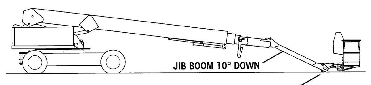
LOWER MAIN BOOM UNTIL JIB IS JUST ABOVE GROUND
Preparation for Stow- N -Go™ Mode Tie Down of Unit.
- b. Rotate the platform 90°, so it is on the right side of the boom.
- c. Exit the platform. Clean the hinge pin of foreign material to allow ease of jib swing. Lubricate with dry moly if necessary.
- d. The boom stowage lock pin has a 5 Ft (1.5 M) long pull chain attached for ease of use. Remove the grip end of the pull chain from its stored position on the left side of the main boom, and let it hang free.
Page 2-56
FRANSPORTING THE UNIT
FRANSPORTING THE UNI
TRUCK OR TRAILER TRANSPORT, BOOM IN STOW- N -GO™ MODE (CONTINUED)
2. To place the boom in the Stow- N -Go™ position (continued):

Removal of hinge boom lock pins will disable platform electrical controls.
With boom lock pins out of "Operational Mode" position (see illustration previous page), do not place any load in the unsupported platform.
e. Remove the hitch pins, and the two lock pins from the hinge boom Stow- N -Go™ connection.
If lock pins do not readily come out, lower main boom (from ground controls) so that slight pressure is applied to the jib boom tip by contact with the truck or trailer bed. Tap the lock pins out with a hammer.
f. Pull the pin holding the boom support stand strut to the underside of the base boom, and swing the boom support column down. The main boom may have to be raised slightly to allow the support column to swing down completely. Pin the strut to the column.

Preparation for Stow- N -Go™ Mode Tie Down of Unit.
TRUCK OR TRAILER TRANSPORT, BOOM IN STOW- N -GO™ MODE (CONTINUED)
2. To place the boom in the Stow- N -Go™ position (continued):

Main boom must be horizontal when rotating jib boom into STOW- N -GO™ position.
- g. From ground control, raise main boom to horizontal and lower jib boom until it is 60° below the main boom.
- h. Swing platform and jib boom assembly to side position. Pull the boom stowage lock pin chain, then position the jib boom assembly until the pin holes line up, then release the chain to allow the spring-loaded pin to lock the jib boom in place. Store lock pins removed in step "e" in hinge boom holes.
- i. Lock the superstructure to the undercarriage by installing the lock pin provided.
- j. Raise the boom to allow greater ground clearance so that the platform will clear any obstacles as the machine goes up the loading ramp.
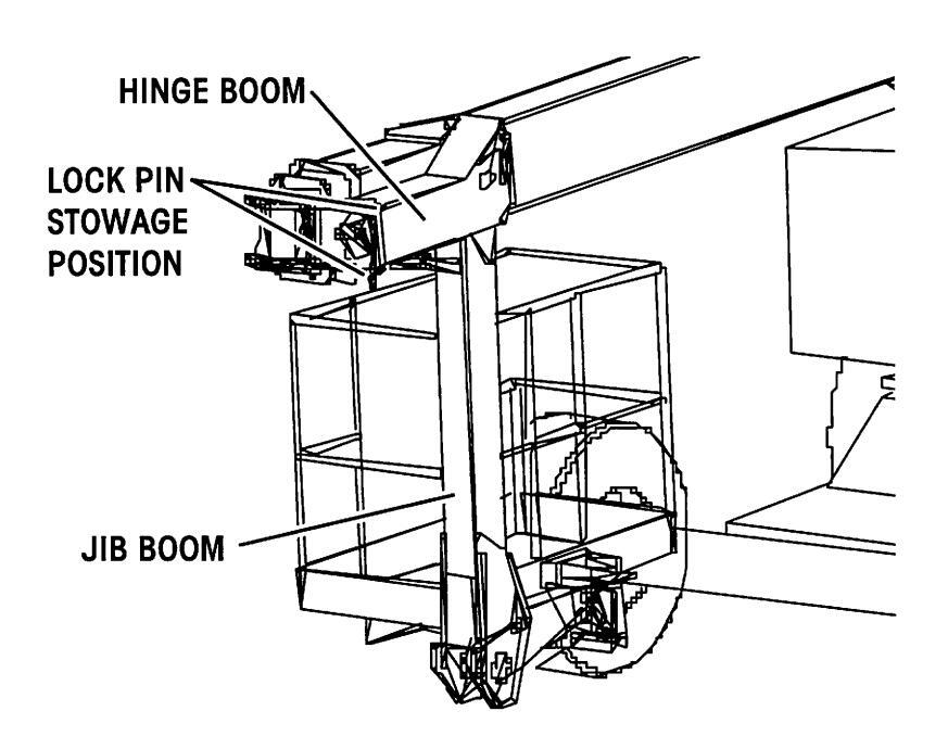
Stow- N -Go™ Storage Mode.
TRANSPORTING THE UNIT
TRANSPORTING THE UNIT
TRUCK OR TRAILER TRANSPORT, BOOM IN STOW- N -GO™ MODE (CONTINUED)
2. To place the boom in the Stow- N -Go™ position (continued):

ALWAYS ATTACH THE UNIT TO A WINCH WHEN LOADING OR UNLOADING FROM A TRUCK OR TRAILER. CONNECT WINCH CABLE TO THE TIE DOWN LUGS ON THE UNDERCARRIAGE.
UNASSISTED LOADING OR UNLOADING OF ANY MOBILE PLATFORM IS NOT RECOMMENDED.
- k. Take the remote control pendant, and stand behind the left rear wheel, near the stowed platform. Using a winch, carefully drive the unit onto the truck or trailer.
- 1. Lower the main boom until boom support stand rests firmly on the truck or trailer bed.
A CAUTION
The jib boom should not be raised once the unit is in the STOW- N -GO™ position.
- m. Lower the jib boom to rest on the truck or trailer bed.
- n. With jib resting, enter the platform and press the foot pedal. Use the platform level control to tilt the platform parallel to the surface of the truck or trailer bed.
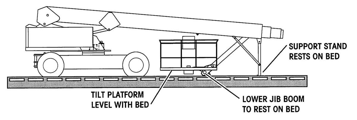
Stow- N -Go™ Mode Tie Down of Unit (Recommended Method).
TRUCK OR TRAILER TRANSPORT, BOOM IN STOW- N -GO™ MODE (CONTINUED)

To avoid damaging the unit, the platform MUST NOT be tied to the trailer bed in any way unless firmly supported on blocks.
Strap (do not chain) the platform to the truck or trailer bed. Avoid overtightening straps.
- o. Place two 14-1/2" (36.8 cm) high support blocks under platform.
- p. Strap the platform to the truck or trailer bed over the platform mid-rail where indicated by decals.
- 3. The negative battery cables should be disconnected for long distance transport. It is recommended that the fuel and hydraulic tank valves be closed as well.
- 4. Tie down locations are located on all four corners of the undercarriage, and at the base of the jib boom. Use one (1) 1/2 inch, "Grade 7" chain from each of the tie down lugs, and run the chains as shown in the diagram below.
Ratchet type load binders are recommended. If using lever type load binders, wire or strap them shut, or wrap chains around them to prevent opening.
5. With machine anchored securely and with lock pin in place, further secure the unit with two (2) 4 inch straps: one wrapped over the front of the undercarriage, and the other over the rear. See illustration below.
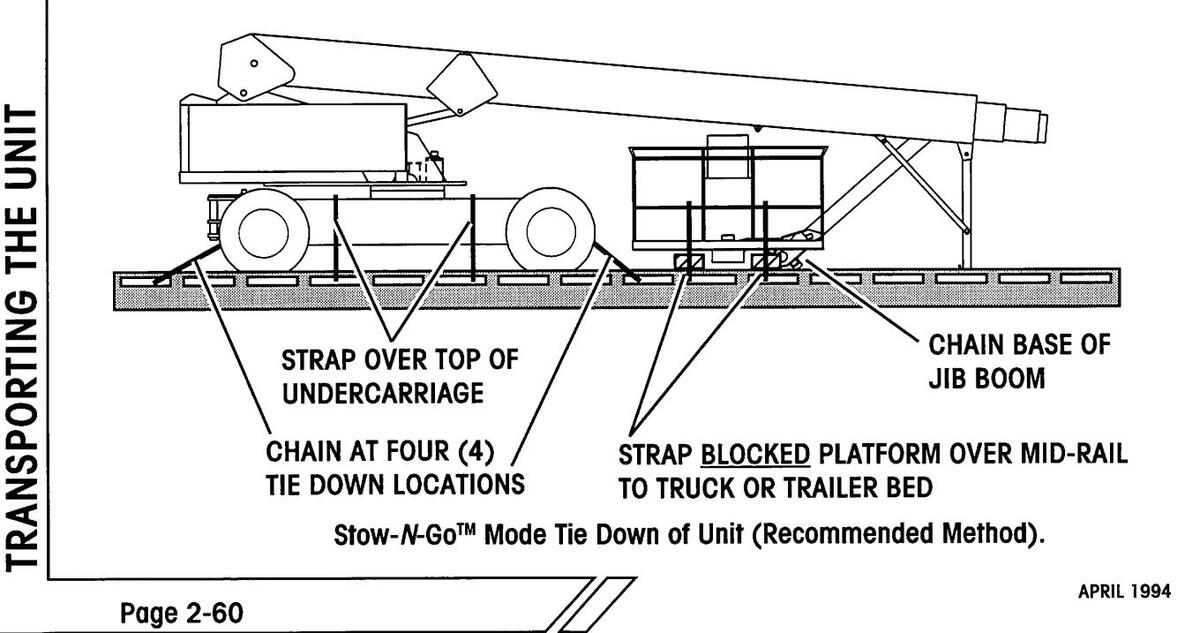
IRANSPORTING THE UNIT
TRUCK OR TRAILER TRANSPORT, BOOM IN CONVENTIONAL MODE
NOTE: Due to the length of the RP 120, transporting without first placing the jib boom in Stow- N -GoTM Mode is normally not practical.
With boom in operational mode and axles retracted:
- 1. Enter the platform, and start the engine using the platform controls. Select the "OPERATING" engine speed.
- 2. Raise the boom to allow greater ground clearance so that the platform will clear any obstacles as the machine goes up the loading ramp.

ALWAYS ATTACH THE UNIT TO A WINCH WHEN LOADING OR UNLOADING FROM A TRUCK OR TRAILER. CONNECT WINCH CABLE TO THE TIE DOWN LUGS ON THE UNDERCARRIAGE.
UNASSISTED LOADING OR UNLOADING OF ANY MOBILE PLATFORM IS NOT RECOMMENDED.
- 3. Using a winch, carefully drive the unit onto the truck or trailer. Selecting drive will release brakes.
- 4. Lock the superstructure to the undercarriage by installing the lock pin provided.
- 5. If placing the boom in the Stow- N -Go™ position is not desired, ensure that the main boom is fully retracted.
Pull the pin holding the boom support stand strut to the underside of the base boom, and swing the boom support column down. The main boom may have to be raised slightly to allow the support column to swing down completely. Pin the strut to the column.
Lower the main boom until boom support stand rests firmly on the truck or trailer bed. Lower the jib boom so the tip rests on the truck or trailer bed. Then, use the platform level lever to rest the platform base on the bed of the truck or trailer.
TRUCK OR TRAILER TRANSPORT, BOOM IN CONVENTIONAL MODE (CONTINUED)
To avoid damaging the unit, the platform MUST NOT be tied to the trailer bed in any way and should only REST on the bed.
- 6. The negative battery cables should be disconnected for long distance transport. It is recommended that the fuel and hydraulic tank values be closed as well.
- 7. Tie down locations are located on all four corners of the undercarriage and at the base of the jib boom. Use four (4) 1/2 inch, "Grade 7" chains from each of the tie down lugs, and run the chains as shown in the diagram on the facing page.
Ratchet type load binders are recommended. If using lever type load binders, wire or strap them shut, or wrap chains around them to prevent opening.
8. With machine anchored securely and with lock pin in place, further secure the unit with two (2) 4 inch straps: one wrapped over the front of the undercarriage, and the other over the rear. See illustration below.
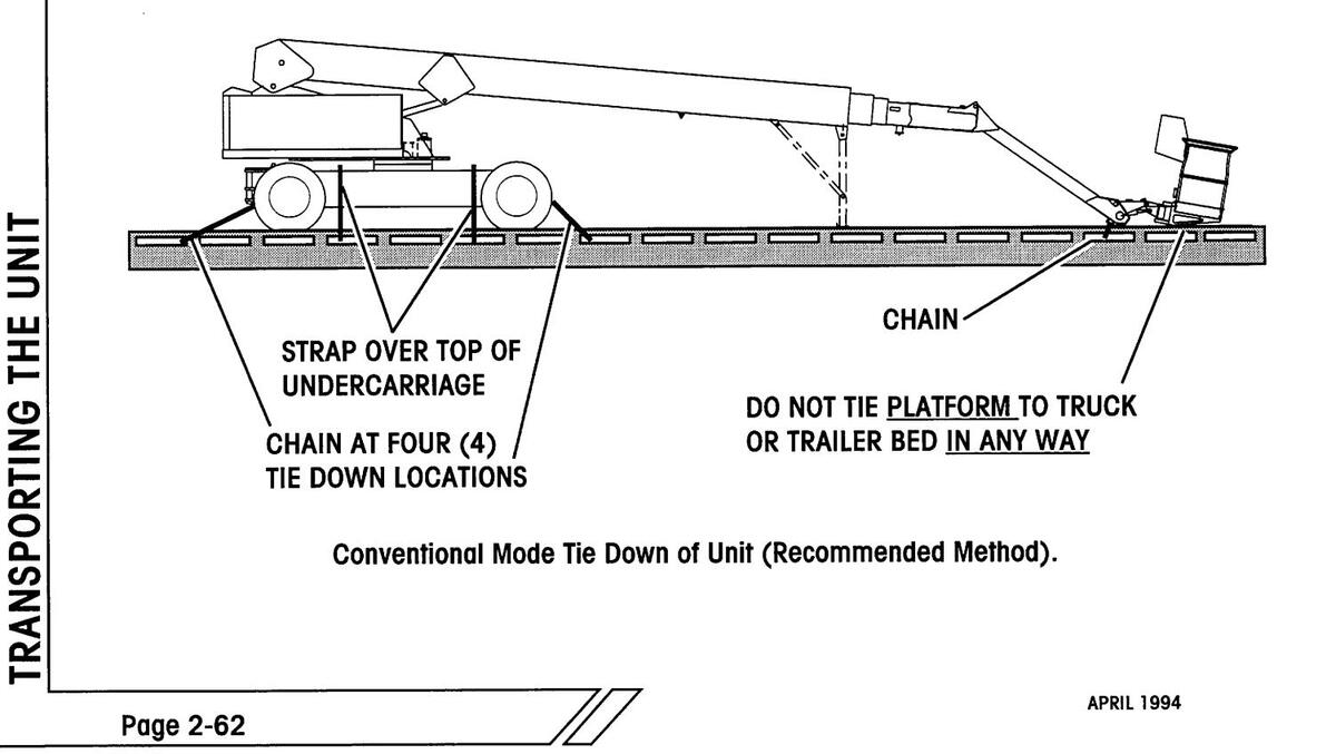
EMERGENCY SYSTEM AND PROCEDURES

IF THE UNIT FAILS WHILE THE OPERATOR'S PLATFORM IS RAISED OR EXTENDED, DO NOT ATTEMPT TO CLIMB DOWN THE BOOM ASSEMBLY. SERIOUS INJURY MAY RESULT.
EMERGENCY ELECTRICAL PUMPS
The RP 120 Mobile Platform has two emergency pumps connected in tandem which can be operated from the platform or ground control station to briefly operate the machine when the unit has lost engine power.
• Press and hold the emergency pump button on the remote control pendant, or
Press and hold the auxiliary pump button on the platform control console.
• Select the proper function as desired to fit the situation.
If attempting to both lower and retract the boom from near maximum reach, battery power can be conserved by using the "RETRACT" function to bring the boom in to less than 60 Ft (18.3 M) extension BEFORE selecting the boom "LOWER" function.
To prevent the batteries from completely discharging and the emergency pumps from overheating, release the emergency pump button to allow a 30 second rest period after every 30 seconds of operation. Once the unit has been safely positioned, correct the cause of the failure before returning the unit to service.
UNPOWERED EMERGENCY MOVEMENT
Every attempt should be made to restore primary power to the unit before using this procedure.
THIS PROCEDURE REQUIRES RELEASING THE VEHICLE TORQUE HUBS, WHICH RESULTS IN THERE BEING NO MEANS TO STOP THE UNIT'S TRAVEL. SIMON RECOMMENDS USING THIS PROCEDURE ONLY IN CASES OF EMERGENCY, AND ONLY FOR A SHORT DISTANCE.
BE ON GUARD AGAINST UNIT RUNAWAY ON SLOPING SURFACES. MOVEMENT SPEED SHALL NOT EXCEED 1 M.P.H. (1.6 K.P.H.).
- 1. Secure the unit with chains or ropes to the tie down lugs located at the front and rear of the undercarriage. The chains or ropes must be of sufficient capacity to pull the unit.
- 2. Block wheels.
- 3. Close brake circuit needle valve located at the center rear of the undercarriage.
- 4. Disengage torque hubs:
WHENEVER DISENGAGING THE DRIVE TORQUE HUBS OR BEFORE DIS-CONNECTION FROM TOWING VEHICLE, ENSURE THAT THE UNIT CANNOT ROLL.
- Type 1: remove the plate in the center of the torque hub, turn the plate so that the boss faces in, then reinstall the plate.
- Type 2: remove the large hex cap in the center of the torque hub, push in and turn screw slot in the center of the torque hub to line up with the "TOW" mark on the hub, then reinstall the cap.
- 5. Disconnect steer cylinder.
After unblocking the wheels, the unit will be ready to be moved.
After primary power has been restored to the vehicle, engage the torque hubs, reset the brake circuit needle valve, and connect steer cylinder. The machine is now ready for normal operation.
EMERGENCY LOWERING
It is not possible for us to foresee every emergency situation that could arise during operation of this machine. Information on the following pages describes three typical emergency situations, and lists appropriate actions that can be taken.
When faced with an emergency, above all please remember:
- Stay calm.
- Think through the situation before operating the machine.
- Get help if necessary.
SITUATION: Platform elevated, operator not incapacitated, but unit will not respond to platform controls.
POSSIBLE CONDITION:
- One or more functions not operating correctly.
- Unit movement from unselected control lever.
- Unit function will not stop unless power is switched off.
CORRECTIVE ACTION
- 1. Remove foot from foot pedal.
- 2. Press the red emergency stop button.
- 3. Evaluate the nature of the failure. Return to the ground, using the emergency pumps (see "Emergency Electrical Pumps", earlier in this section).
- 4. If unable to return to the ground using the platform controls and the emergency pump, contact an experienced operator to lower the machine using the emergency pump and lowering procedure (see "Emergency Electrical Pumps", earlier in this section).
DANGER
DO NOT TRY TO CLIMB DOWN THE BOOM.
HAVE AN EXPERIENCED OPERATOR USE THE EMERGENCY PUMPS TO SAFELY LOWER THE PLATFORM.
5. Report the incident to your supervisor immediately.
Page 2-66
EMERGENCY SYSTEM AND PROCEDURES
SITUATION: Unit elevated, with operator incapacitated at platform controls.
DO NOT TOUCH UNIT !!!
DETERMINE THE CAUSE OF THE PROBLEM BEFORE YOU TOUCH THE MACHINE.
CORRECTIVE ACTION
- 1. Have someone summon first aid or rescue squad.
- 2. Attempt to talk to operator before taking any rescue measures.
-
3. Before attempting emergency lowering procedure, check to see if the operator is:
- in a pinned position, or
- would be endangered if platform is moved.
- 4. After establishing that the machine is not in contact with live power lines, lower the platform or move the unit as necessary, using emergency procedures (see "Emergency Electrical Pumps" or "Unpowered Emergency Movement", earlier in this section).
- 5. Render first aid to the operator.
- 6. Report the incident to your supervisor immediately.
IMPORTANT: Any incident involving personal injury must be immediately reported to the local Simon Aerials Distributorship as well as to Simon Aerials Inc.
SITUATION: Platform in contact with live power lines and operator incapacitated.
DO NOT TOUCH UNIT !!!!
ELECTROCUTION HAZARD !!!!
CORRECTIVE ACTION
- 1. Have someone summon first aid or rescue squad.
- 2. Contact authorized personnel to disconnect power supply touching unit.
-
3. If operator is unconscious, check to see if he is:
- in a pinned position, or
- would be endangered if platform is moved,
before attempting emergency lowering.
- 4. AFTER POWER IS CUT, lower the platform or move the unit as necessary, using emergency procedures (see "Emergency Electrical Pumps" or "Unpowered Emergency Movement", earlier in this section).
- 5. Report the incident to your supervisor immediately.
IMPORTANT: Any incident involving personal injury must be immediately reported to the local Simon Aerials Distributorship as well as to Simon Aerials Inc.
RP 120 REACH PLUS OPERATOR'S MANUAL
MAINTENANCE
SECTION 3: MAINTENANCE

Table of Contents, Section 3
Maintenance
| General Maintenance Tips | 3-3 |
|---|---|
| Shift Operational Checklist | 3-4 |
| Weekly Operational Checklist | 3-7 |
| Monthly Operational Checklist | 3-9 |
| Semi-annual Operational Checklist | 3-11 |
| Troubleshooting | |
| What to check if unit will not start: | 3-13 |
| What to check if functions will not operate: | 3-13 |
| Lubrication Chart | 3-14 |
MAINTENANCE
GENERAL MAINTENANCE TIPS
- Never leave hydraulic components or hoses open. They must be protected from contamination (including rain) at all times.
- Never open a hydraulic system or engine when there are contaminants in the air.
- Use only recommended lubricants. Improper lubricants or incompatible lubricants may be as harmful as no lubrication.
- ALWAYS clean the surrounding area before opening hydraulic or engine systems.
- Watch for makeshift "fixes" which can jeopardize safety as well as lead to more costly repairs.
- Any work platform found not to be in safe operating condition should be removed from service until repaired. All repairs should be made by authorized personnel in conformance with the manufacturer's operating, maintenance, and repair manuals.
SHIFT OPERATIONAL CHECKLIST
All checks must be completed before operation of the unit.
These checklists can be copied as needed to aid in performing these inspections.
| DATE: | INSPECTED BY: |
|---|---|
| SERIAL NUMBER: |
GENERAL INFORMATION
- 1. Keep inspection records up-to-date.
- 2. Record and report all discrepancies to your supervisor.
- 3. A dirty machine cannot be properly inspected. Keep your Simon RP 120 clean!!
THIS CHECKLIST MUST BE USED AT DAILY INTERVALS OR AFTER EVERY 6 TO 8 HOURS OF USE, WHICHEVER IS SOONER. FAILURE TO DO SO COULD ENDANGER THE LIFE OF THE OPERATOR. ALWAYS REMEMBER, A LITTLE PREVENTIVE MAINTENANCE CAN SAVE MUCH MORE THAN IT COSTS.
INITIAL
DESCRIPTION
- 1. Check unit for any prior-shift or transportation damage, i.e. missing parts, torn or loose hoses, hydraulic fluid leaks, torn or disconnected wires, flat or damaged tires etc. The compartment doors on both sides can be opened to inspect components inside.
- 2. Check for unit damage, broken welds, improper or makeshift repairs.
- 3. Check hydraulic system for leaks, examine hoses for signs of excessive wear, chafing or twisting. Adjust the hoses and/ or replace them if necessary (refer to RP 120 Service Manual).
- 4. Check engine oil and fuel levels.
- 5. Check engine coolant level (liquid cooled engine only).
Continued on following page .
Page 3-4
CHECKLIST
SHIFT OPERATIONAL CHECKLIST (CONTINUED)
| INITIAL | DESCRIPTION | |||
|---|---|---|---|---|
|
6. Check battery electrolyte level. Check battery terminals for tight connec-
tions and cleanliness. |
||||
| 7. Check hydraulic fluid level. The level should be at the line marked on the sight gauge with the unit in stowed position. Inspect condition of hydraulic fluid in the reservoir. Fluid should be a clear amber color. | ||||
|
||||
| 9. Check tires for cracks or other damage, and proper inflation pressure (see specifications). | ||||
| O. Check if wheel lug nuts are tight. | ||||
|
||||
| 2. Check hose carrier to verify that it is not bent or sagging. | ||||
| 3. Inspect safety belt connections, and check for worn areas on the belts. | ||||
|
||||
| 5. Check pivot pins and STOW- N -GO ™ hinge and lock pins for security. | ||||
| 6. Check that no attempt had been made to override the drive interlock system by a previous operator. | ||||
| 7. Check that all warning and instructional labels are legible and secure. | ||||
| 8. Start engine. Check that hydraulic pressure is as stated in the machine specifications. | ||||
| 9. Check that the tilt alarm is working properly. | ||||
| 20. When all pre-inspection checks have been completed, test the ground controls for proper operation. | ||||
Continued on following page .
CHECKLIST
SHIFT OPERATIONAL CHECKLIST (CONTINUED)
| INITIAL | DESCRIPTION | ||
|---|---|---|---|
| 21. | Check emergency pumps for operation and that pressure is as stated in the specifications. | ||
| 22. | Check platform controls and graphic display for proper operation. | ||
| 23. | With the platform raised, check for the smooth operation of creep speed drive. | ||
| 24. |
Follow engine daily service requirements. Refer to the Engine Mainte-
nance Manual supplied with your RP 120. |
||
ADDITIONAL MAINTENANCE REQUIREMENTS FOR HARSH ENVIRONMENTS
NOTE: Do not lubricate wear pads or boom cables in dusty or sandblast environments. There are boots and guards available to extend unit life in these applications. Consult Simon Aerials Service Department.
| INITIAL | DESCRIPTION | |
|---|---|---|
|
cuts or other damage
place if necessary. |
|
|
t (8) hours of | |
|
• Follow engine severe usage service requirements.
Maintenance Manual supplied with your RP 120. |
Refer to the Engine | |
| Page 3-6 | APRIL 1994 |
| 00 100 | ODEDATODIC | BRANITAL |
| UPERATUR 3 |
CHECKLIST
WEEKLY OPERATIONAL CHECKLIST
DATE: INSPECTED BY:
MODEL NUMBER: SERIAL NUMBER:
These checklists can be copied as needed to aid in performing these inspections
GENERAL INFORMATION
- 1. Keep inspection records up-to-date.
- 2 Record and report all discrepancies to your supervisor.
- 3 A dirty machine cannot be properly inspected Keep your Simon RP 120 clean!!

THIS CHECKLIST MUST BE USED AT WEEKLY INTERVALS OR EVERY 25 HOURS WHICHEVER OCCURS FIRST. FAILURE TO DO SO COULD ENDANGER THE LIFE OF THE OPERATOR. ALWAYS REMEMBER. A LITTI F PREVENTIVE MAINTENANCE CAN SAVE MUCH MORE THAN IT COSTS.
| INITIAL DESCRIPTION | ||
|---|---|---|
| 1. | Perform all checks listed on Shift Operational Checklist. | |
| 2. | Check wheel lug nut torque (see specifications). | |
| 3. | Check electrical connections at the hinge boom for tightness and corrosion. Check hydraulic connections for leaks, corrosion and wear. | |
| 4. | Lubricate swing bearing and drive pinion gear. | |
| 5. | Apply lubricant to standard open swing bearing and drive pinion gear (see Lubrication Chart). | |
|
Check lubricant in optional oil bath swing bearing case, if so equipped, for proper level, and check for dirt or metal contamination (see Lubrica-
tion Chart). |
||
| 6. | Lubricate the hinge boom hinge and lock pins. | |
Continued on following page .
WEEKLY OPERATIONAL CHECKLIST (CONTINUED)
ADDITIONAL MAINTENANCE REQUIREMENTS FOR HARSH ENVIRONMENTS
NOTE: Do not lubricate wear pads or boom cables in dusty or sandblast environments. There are boots and guards available to extend unit life in these applications. Consult Simon Aerials Service Department.
| INITIAL | DESCRIPTION |
|---|---|
| Lubricate all grease fittings (see Lubrication Chart). | |
| Check oil level in swing drive (see Lubrication Chart). | |
| • Check oil level in power hubs (see Lubrication Chart). | |
|
CHECKLIST
CHECKLIST
MONTHLY OPERATIONAL CHECKLIST
DATE: INSPECTED BY:
MODEL NUMBER: SERIAL NUMBER:
These checklists can be copied as needed to aid in performing these inspections.
GENERAL INFORMATION
- 1 Keen inspection records up-to-date
- 2. Record and report all discrepancies to your supervisor.
- 3 A dirty machine cannot be properly inspected. Keep your Simon RP 120 clean!

THIS CHECKLIST MUST BE USED AT MONTHLY INTERVALS OR EVERY 100 HOURS, WHICHEVER OCCURS FIRST. FAILURE TO DO SO COULD ENDANGER THE LIFE OF THE OPERATOR. AI WAYS REMEMBER, A LITTLE PREVENTIVE MAINTENANCE CAN SAVE MUCH MORE THAN IT COSTS.
| INITIAL | DESCRIPTION |
|---|---|
| 1. Perform all checks listed on Shift and Weekly Operational Checklists. | |
| 2. Lubricate all grease fittings (see Lubrication Chart). | |
| 3. Lubricate all hydraulic valve spool linkages. | |
|
|
|
|
|
|
| 7. Check torque of swing bearing bolts (see "Machine Specifications"). |
Continued on following page .
MONTHLY OPERATIONAL CHECKLIST (CONTINUED)
| INITIAL | DESC | RIPTION | ||
|---|---|---|---|---|
|
||||
| 9. | Check oil level in swing drive gear box (see Lubric | ation Chart). | ||
| 10. | Check oil level in power hubs (see Lubrication Che | art). | ||
| 11. | Check that tires are not leaning in or out. | |||
| 12. | Check that wheel spindles turn freely, with no end | play. | ||
| 13. | Check drive wheel power hub mounting bolt torque Specifications"). | e (see "Machine | ||
| 15. |
Check that neither the main boom nor jib boom dr
hydraulic pressure (engine off) and the controls in position. |
ift with a full load, no
the "BOOM DOWN" |
||
| 16. | Inspect boom cables. | |||
| 17. Check to make sure boom sections are not dented or bent. | ||||
| 18. | Check that all adjustable flow valves are locked. Check settings if any are not locked. | |||
| 19. | Check fuel shutoff rack for proper operation. Loos lubricate with WD-40 or equivalent. | en lever arm and | ||
| 20. |
Follow engine monthly service requirements. Refe
Maintenance Manual supplied with your RP 120. |
r to the Engine | ||
| AINTENAN | ITS | |||
| EVERY 90 DAYS | ||||
| INITIAL | DESC | RIPTION | ||
| ٠ | Replace high pressure filter element. | |||
| ٠ |
Follow engine severe usage service requirements.
Maintenance Manual supplied with your RP 120. |
Refer to the Engine | ||
| age 3-10 | APRIL 1994 | |||
Page 3-10
CHECKLIST
| DD ' | 120 | DEACH | DIIIC | ODEDATODIC | MANITAL |
| NE | 20 | NLAUI | FLUG | OF LKAIVK J | INIANUAL |
CHECKLIST
SEMI-ANNUAL OPERATIONAL CHECKLIST
DATE: INSPECTED BY:
MODEL NUMBER: SERIAL NUMBER:
These checklists can be copied as needed to aid in performing these inspections.
GENERAL INFORMATION
- 1. Keep inspection records up-to-date.
- 2. Record and report all discrepancies to your supervisor.
- 3. A dirty machine cannot be properly inspected. Keep your Simon RP 120 clean!!
AWARNING
THIS CHECKLIST MUST BE USED AT SIX MONTH INTERVALS OR EVERY 500 HOURS, WHICHEVER IS SOONER. FAILURE TO DO SO COULD ENDANGER THE LIFE OF THE OPERATOR. ALWAYS REMEMBER, A LITTLE PREVENTIVE MAINTENANCE CAN SAVE MUCH MORE THAN IT COSTS.
| INITIAL | DESC | SCRIPTION | |
|---|---|---|---|
| 1. | Perform all checks listed on Shift, Weekly and Monthly operational checklists. | ||
| 2. | Have hydraulic fluid sample analyzed at a test laboratory. Comply with test results and recommendations to ensure long, trouble free operation. | ||
| NOTE: If hydraulic fluid has been regularly maintained, it should only require changing once every year, depending on maintenance, temperature, application, duty cycle, and atmospheric conditions. | |||
| 3. | Inspect the entire machine for signs of structural damage and broken welds, and worn or damaged components. Replace as necessary. | ||
| 4. | Clean and lubricate all electrical switches with an electrical contact cleaner and ensure that the switches operate freely in all positions. | ||
| 5. | Check the electrical mounting and hardware connections for security. | ||
Continued on following page .
SEMI-ANNUAL OPERATIONAL CHECKLIST (CONTINUED)
| INITIAL | DESCRIPTION | |||
|---|---|---|---|---|
| 6. | Replace high pressure filter elements. | |||
| 7. | Clean and lubricate the standard open swing bearing gear teeth with dry moly lube spray (not required for oil bath swing bearing). | |||
| 8. | Repack front wheel bearings. | |||
| 9. | Check that engine RPM is as stated in the specifications. | |||
| 10. | Follow engine semi-annual service requirements. Refer to the Engine Maintenance Manual supplied with your RP 120. | |||
| EVER | RY YEAR | |||
| 11. | Drain and replace fluid from hydraulic reservoir. Drain and replace fluid from drive wheel power hubs. If badly contaminated, it may be necessary to disassemble and inspect components. | |||
| EVERY TWO YEARS | ||||
| 12. | Drain and replace fluid from swing drive. If badly contaminated, it may be necessary to disassemble and inspect components. | |||
| MAINTENAN | CE REQUIREMENTS FOR HARSH ENVIRONMENTS | |||
| EVER | RY SIX MONTHS | |||
| ٠ | Drain and replace fluid from swing drive and drive wheel power hubs. | |||
| • | Follow engine severe duty service requirements. Refer to the Engine Maintenance Manual supplied with your RP 120. | |||
|
|
||||
| Page 3-12 | APRIL 1994 | |||
CHECKLIST


 Loading...