

Page 1

Page 2
il
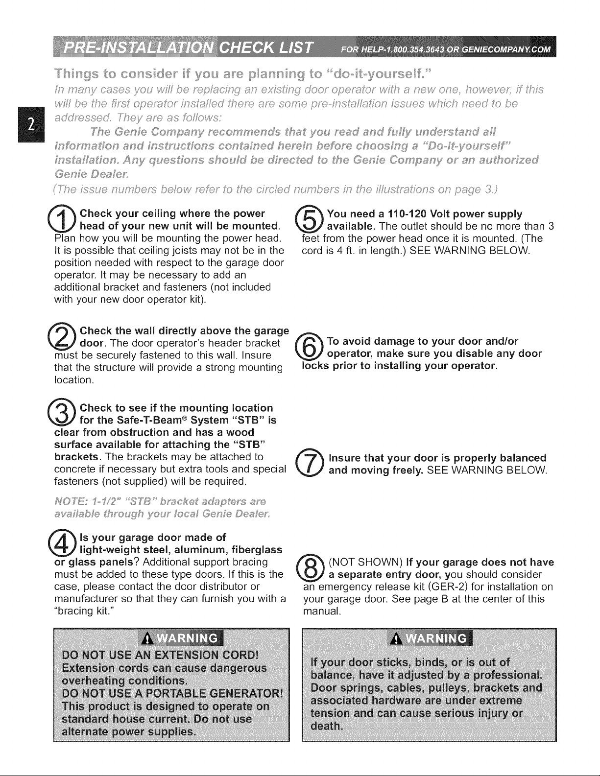
Check your ceiling where the power
head of your new unit will be mounted.
Plan how you will be mounting the power head.
It is possible that ceiling joists may not be in the
position needed with respect to the garage door
operator. It may be necessary to add an
additional bracket and fasteners (not included
with your new door operator kit).
Check the wall directly above the garage
door. The door operator's header bracket
must be securely fastened to this wall. Insure
that the structure will provide a strong mounting
location.
Check to see if the mounting location
for the Safe-T-Beam ® System "STB" is
clear from obstruction and has a wood
surface available for attaching the "STB"
brackets. The brackets may be attached to
concrete if necessary but extra tools and special
fasteners (not supplied) will be required.
You need a 110-120 Volt power supply
available. The outlet should be no more than 3
feet from the power head once it is mounted. (The
cord is 4 ft. in length.) SEE WARNING BELOW.
To avoid damage to your door and/or
operator, make sure you disable any door
locks prior to installing your operator.
Insure that your door is properly balanced
and moving freely. SEE WARNING BELOW.
as<_flsb/@ tthrx>u£h you_" Iota[ Gen/® D®a @,:
Is your garage door made of
light-weight steel, aluminum, fiberglass
or glass panels? Additional support bracing
must be added to these type doors. If this is the
case, please contact the door distributor or
manufacturer so that they can furnish you with a
"bracing kit."
(NOT SHOWN) If your garage does not have
a separate entry door, you should consider
an emergency release kit (GER-2) for installation on
your garage door. See page B at the center of this
manual.
Page 3

48" POWER
TO
120V GROUNDED
OUTLET
TYPICAL
SUPPORT
BRACKET
EXTENSION
®
@
ADDED
HEADER BRACKET
MOUNTING BOARD
BRACES
OR
TORSION SPRING'
®
SECTmONAL DOOR I-PmECE DOOR
Page 4
SECTION......................................... PAGE
PRE-INSTALLATIONCHECKS.......................... 2-3
OPERATORFEATURES................................. 4
SAFETYFEATURES.................................... 4
TOOLSRECOMMENDED................................ 5
PARTSIDENTIFICATION.............................. 5-7
SAFETYINFORMATION................................. 7
OPERATOR.............................................
1 ASSEMBLY.................................... 8-10
2 INSTALLATION................................ 11-14
ELECTRICALINSTALLATION......................... 15-18
3 SAFE-T-BEAM®SYSTEMINSTALLATION.......... 15-16
4 WALLCONTROLINSTALLATION.................... 17
5 CONNECTOPERATORTOPOWER................. 18 NOTE: Your garage door operator may not come with all above
ADJUSTMENTS.................................... 19-21 items included as standard equipment.
6 LIMITSWITCHES&FORCEADJUSTMENT........... 19.
CONTACTREVERSE............................. 20
7 PROGRAMMINGREMOTECONTROLS........... 20-21
8 BATTERY/VISORCLIPINSTALLATION............... 21
9 LIGHTBULBANDLENSINSTALLATION.............. 21
SAFETYINSTRUCT!ONS............................... 22
MAINTENANCE&TROUBLESHOOTING............... 22-24
SAFE-T-BEAM®................................. 22
OPERATOR/RADIO.............................. 23
WIRINGDIAGRAM............................... 24
ACCESSORIES...................................... A-B
WARRANTY.......................................... C
INTELLICODE ®Roiling Code Security System.
An electronic rolling code system that enhances the security of
the door operator by continuously changing the access code
each time the remote control is used. The door operator
responds to each new code only once. An access code copied
from a working system and tried again will not control the door
operator.
INTELLICODE ®1, 2 or 3-Button Remote Control (included
with some models).
Operates 1, 2 or 3 garage doors from car.
Lighted Wall Button*.
Operates door operator from inside garage.
Lighted Wall Console* (included with some models).
Security vacation lock switch disables all controls. LED
Indicator shows whether system is locked or unlocked. Makes
console easy to find in dark. Controls door operator from inside
garage. Independent light control allows convenient manual
control of the automatic lighting system.
Safe-T-Beam ®(STB) Non-Contact Reversing System**.
Puts an invisible beam across the door opening. The door stops
and reverses to the full open position if anything passes
through the beam. Red and green LED indicators provide a self
diagnostic code if an operational problem exits.
Safe-T-Reverse ®Contact Reversing System.
Automatically stops and reverses a closing door within 2
seconds of contact with an object.
Safe-T-Stop ®Timed Reversed System.
Automatically opens a closing door if it fails to close completely
within 30 seconds.
Force Guard ®Control.
Features adjustable open and close force settings. For
maximum safety, these must be set to the minimum force
required to fully open and close the door.
Relay Monitoring System.
Automatically stops and reverses a closing door if the closing
relay malfunctions.
Watch Dog ®Monitoring System.
Automatically stops and reverses a closing door if the
Safe-T-Beam System** has an operational problem.
Automatic Lighting System.
One bulb lighting supplies up to 100 Watts of light for safer
evening exits and entries. Turns on when door _sactivated and
automatically turns off 5 minutes later.
Manual Emergency Release.
Manually releases door from door operator. Use during a power
failure or other emergency to allow manual opening and closing
of door.
Page 5

Drill
Ratchet
Pencil
Carpenter's level
Adjustablewrench
Stepladder
#6 x 1-1t4" Pan (32)
Head Phillips
Screw Wall console
r_
5/32"DrillBit
©
7/16"and 9/16"
Sockets
@
Safety Brochure
#10-16 x 1-1t4"
Machine Screw
%
Tape measure
Phillipsscrewdriver
oRI
Single-button Multi-button
remote control remote control
Q
@
Wire
Wire strippers
,&WARNING
@
EntrapmentWarning
Label
ii
#6 x 1-1/4" Pan
Head Phillips
Screw Wallbutton
[9]
Bolt - 1/4"-20 x 5/8"
0
[10]
Nut - 1/4'L20
SourceSTB SensorSTB
(Red LED) (Green LED)
[22]
Lag screw - 1/4" x 2"
[25]Cotter0in
@
[28]
Nut - 3/8"-16
[39]
Screw -#8-32 x 1"
STBBracket
lnsu_taple
[41]Wirec'i0
[42]
Self-drilling Screw
1/4'L20x 3/4"
[24]C,evispin
[27]
Bolt - 3/8"-16 x 7/8"
[46]
Bolt - 5/16"-18 x 3/4"
[47]
Nut - 5/16"-18
Page 6

@
/
\
\
Page 7
ItemPartName
Powerheadassembly(box) 1 1
Railassembly(1-piece#box) 1
Rail(1-piece)(box) 1
Railassembly(3-piece)(items5,6,7)(box) 1
Firstrailsection(box) 1
Middlerailsection(box) 1
Endrailsection(box) 1
Railclamp(bluebag) 4
1/4"-20x5/8"hexheadbolt(blueba@) 4 12
10 1/4"-20hexflangenut(bluebag) 4 12
11 Carriageassembly(box) 1 1
12 Railstrap(bluebag) 1 1
13 LimitswitchOPEN(whitewire)(greenbag) 1 1
14 LimitswitchCLOSE(brownwire)(greenbag) 1 1
15 Releasecord(greenbag) 1 1
16 Releaseknob(greenbag) 1 1
17 Emergencyreleasetag(greenbag) 1 1
18 Headerbracket(orangebag) 1 1
!0 Doorbracket(orangebag) 1 1
!2 1/4"x2"lagscrew(orangebag) 8 8
!3 Straightdoorarm(box) 1 1
!4 Clevispin(yellowbag) 2 2
!5 Cotterpin(yellowbag) 2 2
!6 Curveddoorarm(box) 1 1
!7 3/8"-16x 7/8"hexheadbolt(yellowbag) 2 2
!8 3/8"-16hexflangenut(yellowbag) 2 2
!9 Wire(box) 1 1
30 Insulatedstaple(redbag) varies/modelvaries/model
31 Wallbutton(redbag) varies/modelvaries/model
32 Wallconsole(box) varies/modelvaries/model
33 No.6x 1-1/4"panheadphillipsscrew(redbag) varies/modelvaries/model
34 EntrapmentWARNINGlabel(manual) 1 1
35 Safe-T-Beam(STB)sensor(greenLEa)(box) 1 1
36 Safe-T-Beam(STB)source(redLEa)(box) 1 1
37 Safe-T-Beam(STB)bracket(yellowbag) 2 2
38 Remoteoperator(box) varies/modelvaries/model
39 #8-32x 1"machinescrew(greenbag) 2 2
_0 Safety&maintenanceguide(manual) 1 1
H Wireclip(greenbag) varies/modelvaries/model
$2 1/4"-20x3/4"self-drillingscrew(orangebag) 3 3
N #10-16x1-1/4"phillipshexheadscrew(yellowbag) 4 4
_6 5/16"-18x 3/4"hexheadbolt(orangebag) 3 3
$7 5/16"-18hexflangenut(orangebag) 4 4
$8 MountingStraps(box) 2
NumberRequired
1pc,rail 3pc,rail
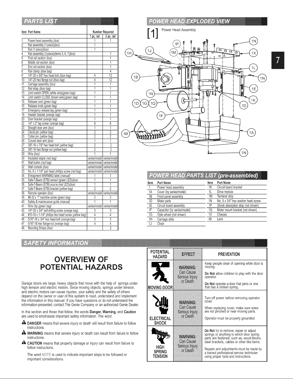
1] Power Head Assembly
Item PartName
I Powerheadassembly
1A Cover(byseries/model)
IB Frontpanelassembly
1D Motorparts
1E Circuitboardassembly
1F Capacitor(byseries/model)
1G Optowheel(notshown)
IH Carriageslide
lJ Chain
I
Item PartName
IK Circuitboardbracket
1L Drivemodule
1M Terminalstrip
1N No.8x3/4"hexwasherheadscrew
IP Shockabsorptionstopn(notshow_
1Q Motormountbracket(notshown)
1X Chassis
49 Lens
OVERVIEW OF
POTENTIAL HAZARDS
Garagedoors are large, heavyobjectsthat movewith the helpof springs under
high tension andelectric motors.Since movingobjects, springs under tension,
andelectric motors can causeinjuries,your safety andthe safety of others
dependon the owneror userof this system to read, understandand implement
theinformation in this manual. If you have questionsor do not understandthe
informationpresented,contactThe GenieCompany or anauthorizedGenieDealer.
In this section and those that follow,the words Danger, Warning, and Caution
are usedto emphasizeimportant safety information.The word:
DANGER meansthat severe injuryor death will resultfrom failure tofollow
instructions.
_. WARNING meansthat severe injury or death can result from failure to follow
instructions.
£i. CAUTION means that property damageor injury can resultfrom failure to
follow instructions.
Theword/_2Oi'Eis used to indicate importantstepsto befollowed or
importantconsiderations.
POTENTIAL
HAZARD
ELECTRICAL
SHOCK
HiGH
SPRING
TENSION
PREVENTION
Keeppeopleclearof openingwhiledooris
mowng.
Do Not allowchildrento playwith thedoor
operator.
Do Not operatea doorthatjamsorone
thathasa brokenspring.
Turnoff powerbeforeremovingoperator
cover.
Whenreplacingcovermakesurewires
arenotpinchedor nearmovingparts.
Operatormustbeproperlygrounded.
De Net tryto remove,repairoradjust
iiiiiiiiii!iiiii!ii i iii!iiii!!i!iii!!iii!
springsoranythingtowhichdoorspring
partsarefastened,suchas,wood blocks,
steelbrackets,cablesorotherlike items.
Repairsandadjustmentsmustbemadeby
atrainedprofessionalservicetechnician
usingpropertoolsandinstructions.
Page 8
1
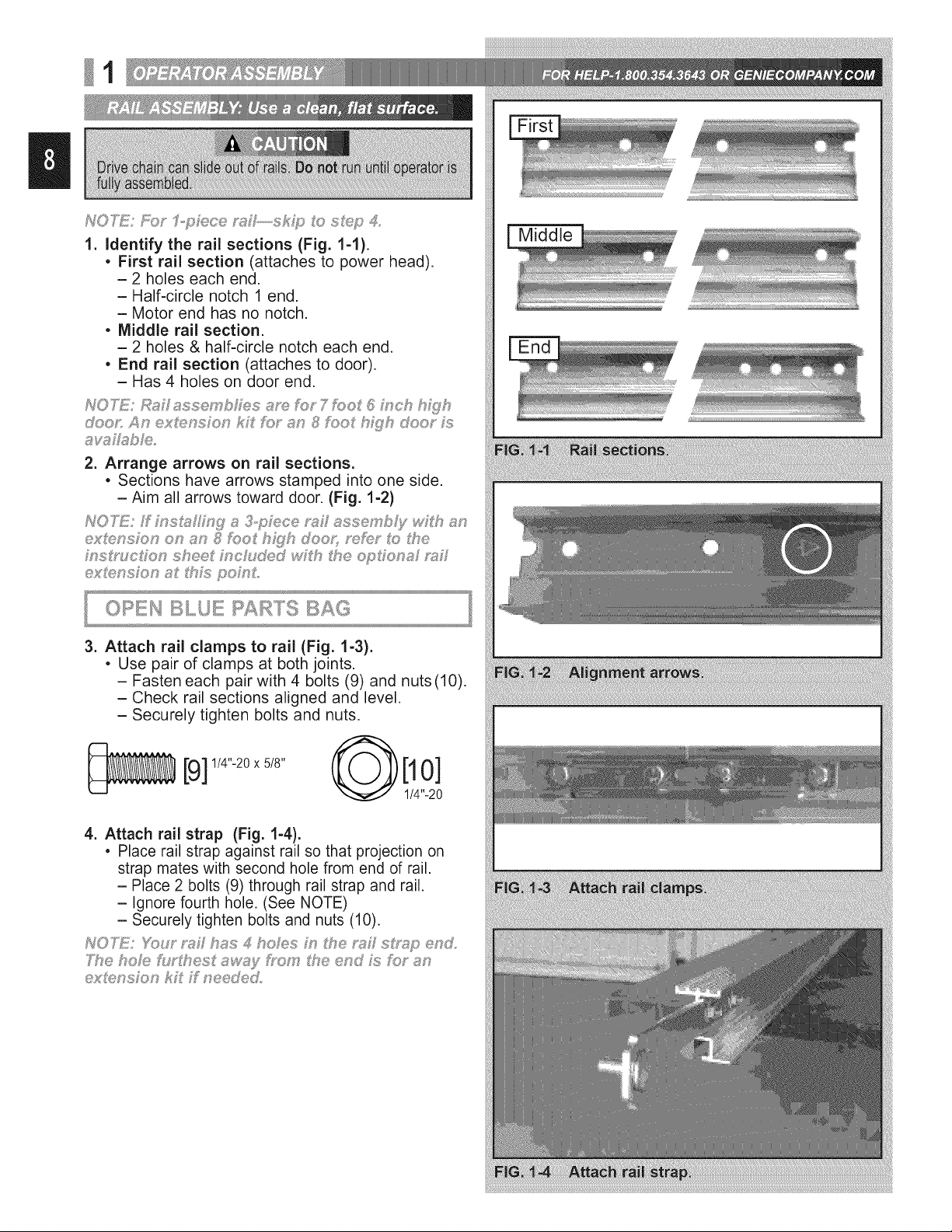
1. Identify the rai! sections (Fig. 1-1).
• First rail section (attaches to power head).
- 2 holes each end.
- Half-circle notch 1 end.
- Motor end has no notch.
• Middle rail section.
- 2 holes & half-circle notch each end.
• End rail section (attaches to door).
- Has 4 holes on door end.
2. Arrange arrows on rail sections.
• Sections have arrows stamped into one side.
- Aim all arrows toward door. (Fig. 1-2)
ex_ensFon on an _ foot h_yh doox_ _f_;_ t_f:_the
3. Attach rail clamps to rail (Fig. 1-3).
• Use pair of clamps at both joints.
- Fasten each pair with 4 bolts (9) and nuts(10).
- Check rail sections aligned and level.
- Securely tighten bolts and nuts.
Middle
[9] 114''-20x518" @[10]
4. Attach rail strap (Fig. 1-4).
• Place rail strap against rail so that projection on
strap mates with second hole from end of rail.
- Place 2 bolts (9) through rail strap and rail.
- Ignore fourth hole. (See NOTE)
- Securely tighten bolts and nuts (10).
cxUf:,nsFon kF Ffneede&
1/4"-20
Page 9

5. Slip carriage into carriage slot of rail.
• Flip the rail assembly up side down.
• Place emergency release lever in "release"
position (See below).
- Check arrow on the side of carriage points
toward door end of rail.
- Slide carriage into rail at power head end
(Fig. 1-5).
- Flip rail assembly right-side up.
6. Attach rail to power head.
* Place rail in front of power head with rail strap at
opposite end.
* Support door end of rail (rail strap) at about same
height as power head.
- Check if magnet is in place (Fig. 1-6 inset). Insert
carriage slide into rail (Fig. 1-6). (Carriage slide is
long straight piece attached to chain.)
- Pull rail toward you as you feed chain into it.
(Fig. 1-6). When the end of the rail is within
about 2 chain links of the power head, you can
then push it the rest of the way. (It is a snug fit.)
- Securely fasten with 2 bolts (9) and nuts (10)
(Fig. 1-7).
9] 1/4"-20x 5/8"
7. Attach emergency release cord, knob and tag.
* Tie overhand knot in 1 end of cord. Tighten knot.
(FIG. 1-8 inset A).
- Slip opposite (no knot) end through knob.
- Slip through hole in emergency release lever
(Fig. 1-8).
- Tie overhand knot in this end also. Tighten knot,
8. Attach emergency release tag.
* Attach to hole in emergency release using metal
twist tie on tag. (Fig. 1-8 inset B).
[10]
1/4"-20
B
overhand knot ]
Lever in release position.
Page 10

g. Attach limit switches.
2 switches included, "CLOSE" limit switch (brown
wire) and "OPEN" limit switch (white wire)
(Fig. 1-10).
• Turn set screws (39) into threaded holes, just
enough so screw stays in place. (Fig. 1-10).
[39]#8_32xi,,
Point arrow on top "CLOSE" limit switch toward
door end of rail.
- Place "CLOSE" limit switch (Brown wire) on rail
about 12" from rail strap (Fig. 1-11).
- Gently tighten set screw enough to keep switch
from moving.
Point arrow on top "OPEN" limit switch toward
door end of rail.
- Place "OPEN" limit switch (white wire) on rail
where chain attaches to carriage slide. (Near
the power head.)
- Gently tighten set screw enough to keep switch
from moving.
10.Attach limit switch wires.
• Uncoil limit switch wires.
- Place into channels located along top of rail.
- Run wires back to power head through hole in top
of power head (Fig. 1-12).
- Use wire clips to hold wires in place (Fig. 1-13).
[41]
• Attach limit switch wires to terminals on power
head (Fig. 1-14).
-White wire ("OPEN") to terminals #4 and #5.
- Brown wire ("CLOSE") to terminals #5 and #6.
• Bundle extra wire and lay it on top of power head
(Fig. 1-14 inset).
Page 11

2
iMPORTANT
Toreducetheriskofsevereinjuryordeath:
1. READAND FOLLOWALL SAFETY, INSTALLATIONAND
OPERATIONINSTRUCTIONS.If you have questions or
do not understand an instruction, call The Genie
Company or an authorized Genie Dealer.
2. Do Not install operator on an improperly balanced door.
An improperly balanced door could cause severe injury.
Repairs and adjustments to cables, spring assembly,and
other hardware must be made by a professionally trained
service technician using proper tools and instructions.
3. Remove all ropes and disable all locks connected to the
door before installing operator.
4. Install door operator 7 feet or more above floor. Mount
emergency release knob 6 feet above floor.
5. Do Not connect the operator to the source of power
until instructed to do so.
6. Locate the control button:
. Within sight of door.
. At minimum height of 5 feet above the highest floor
level, so small children cannot reach it.
. Away from all moving parts of the door.
7. Install the Entrapment WARNING Label next to the wall
button or wall console. Installthe emergency release
tag on, or next to, the emergency release.
8. The operator must reversewhen the door contacts a
1-1/2inch high object on the floor at the center of the
doorway.This is the size of a 2" x 4" board laid flat.
=
Finding header bracket mounting location.
• Close garage door.
-Use a pencil.
a. Mark center of garage door (one-half overall
width) with 6" vertical line at top edge of door.
b. Continue this line on wall above door for
about !2" (Fig. 2-1).
• Raise garage door until top edge of door
reaches its maximum height (Fig. 2-2).
• Place door at highest point.
- Measure height from top edge of door to floor.
• Close door again.
• Mark height measurement on wall above door.
- Make your mark across vertical line
made earlier.
, Marking final height.
TI"_E2 P _s_'__'_'_vlc__::_',OtC_'_:_J',,s #*'_:_DOOR
Sect ons d®o_s,,_,_ave _oe_s on each sde w_c_ _de
One,,,F;*ece do®_s,_sw ve on a%e sp_ s9 oaded
nnges as the doo_ opens a_d coses
• For secdona! - add 2-1/2" to height mark
just made on wall. This is location for
header bracket.
2-?_/;;__aboye s@_;,?£ or shah and mau£ 8hTsheath
,, For one-piece - add 6"- 12" to your height mark
just made on the wall. This is location for
header bracket.
Page 12

NO7_iF;f he_-_oq;)b;"scke ocs_Fo_*_needs o be
_;_bovehesde;' fb;' !is_'_!_!_i'ech::_oopenh, W you
£;,oud seco_,e@ _sched i'@s_one;'s no h_c/ @d}
_;_c;'ossw_d/suo%; o_ eFhe, sM_, of;/o mu£ £_
s f?Ycien (Fig. 2-4)
2. Mounting the header bracket.
seye_x,_ w_ys, mehod _I M pmM_,"_d f_poss b _
bec_se of _d@d s_,ng_h ore;' o_he me hodxs
(Fig, 2-5)
• Hold header bracket against wall (Fig. 2-5).
- Place left edge on vertical line.
- Bottom edge on final height line.
• Mark screw hole locations on wall.
• Drill 5/32" pilot holes at each screw hole mark.
- Fasten header bracket with 3 lag screws (22)
(Fig. 2-5).
1/4" x2"
[22]
3. Finding door bracket mounting location.
• Door bracket is mounted as high on door as
possible along vertical centerline.
b_'_cke mus be moun_s_d NO LOWFZ£ N _op
set of _s_e_s (Fig. 2-7)
_ @ e@e oF @us
4. Mounting the door bracket.
• Proper bracing should be verified at this point,
- Align door bracket centered on your
vertical centerline.
-Attach using 3 self-drilling screws (42) for
sheet metal or other light weight material.
- Use lag screws (22) for solid wooden doors.
[42] 1/4"-20x3/4"
[22]
1/4"x 2"
NO'h_: F;OY' sohaJ wood do@'s c_' ,,_s£ebosLs
X/YYHOUT"SLOTXE© H£A©S pso{ ;_,s*cudis@ m#_y
atso be used fbr a _:_sch#'_!_doo_" b_s!_ceL
Page 13

1. GettingStarted.
• Positionrail/powerheadassembly(Fig.2-7).
- Railstrapleaningonwallnexttoheaderbracket.
-Place materialonfloorunderpowerheadto
protectfromscratching.(Abox,stool,orsimilar
devicemaybeneededtocleara torsion
spring,asshown.)
2, Mountingthe assembly.
• Attachrailstraptoheaderbracketusingnut(47)
(Fig.2-7inset).FINGERTIGHTONLY.
[47]
5/16"-18
J
HEADER BRACKET
DOOR
• Support power head on step-ladder.
NO}_1Y Beh:_ye £_a,_ s SxJ_ch£en {to ceh£ng, msu_'e
tha£ asse _,Ls,_}/h m phspe_ a_V{i_n_'en£(Fig. 2-9).
• Attach mounting straps to ceiling using lag
bolts (22) (Fig. 2-10).
• Set height of power head according to following:
- Track guided doors.
a. Rail must clear door at highest point of travel
b. Be level or, power head slightly below level.
- Trackless doors.
a. Rail must clear door at highest point of travel
by 1" to 1-1/2".
• Securely tighten power head mounting bolts (46)
and nuts (47).
• Lower door.
• Fully tighten rail strap nut.
• DO NOT PLUG UNIT IN YET!
3. Adjusting length of emergency release cord.
• Check emergency release knob height.
-Low enough you can reach it.
-High enough to clear your vehicle, but
NO HIGHER THAN 6 FEET ABOVE FLOOR.
• Tie a new overhand knot where desired.
-Cut off any extra cord.
90 °
VIEW FROM ABOVE
(not to scale)
ANGLE IRON ON FINISHED CEILING
[o ooooooo oj
Attach angle iron to beams
_ _ DRYWALL
UNFINISHED OR OPEN BEAM
Extra framing
not needed
Mounting
[22]
I/4" x2"
[46]
5/16"-18x 3/4
[46 &
[46 &
_, Extra framing
NEEDED
Page 14

OPEH YELLOW RTS BAG
1. Attach the arms.
• Fasten curved door arm to door bracket using
clevis pin (24) and cotter pin (25) (Fig. 2-10).
• Straight arm to carriage using clevis pin (24) and
cotter pin (25) (Fig. 2-10).
[24] [25]
2. Connecting the arms.
• Slide carriage back and forth to adjust arm length.
-Overlap arms as much as possible.
- Make overall length as short as possible.
• Fasten arms together using 2 bolts (27) and
nuts (28) (Fig. 2-10). (Place the bolts as far
apart as possible,)
[27]
3/8"-16 x 7/8"
1. Attach the arms.
• Straight arm to door bracket using clevis pin (24)
and cotter pin (25) (Fig. 2-12).
• Curved arm to carriage using clevis pin (24)
and cotter pin (25) (Fig. 2-12).
[24] [25]
2. Connecting the arms.
• Slide carriage back and forth to adjust arm length.
-Overlap arms as little as possible.
-Make overall length as long as possible.
• Fasten arms together using 2 bolts (27) and
nuts (28) (Fig. 2-12).
[27]
3/8"-16x 7/8"
[28]
3/8"-16
Page 15

3
h_O_TE"%h....
1. Mounting brackets.
• Mark both sides of garage door frame or wall 5"
above floor. (Fig. 3-1).
• Hold bracket against door frame or wall.
- Check if brackets extend out from wall far
enough, so tongue of bracket is beyond door,
tracks or any door hardware.
-if not:
a. "STB" bracket extensions are available
at local dealer.
b. Blocks of wood, etc. may be substituted for
extensions.
• Center bracket on your mark (Fig. 3-2).
• Fasten each with 2 screws (44) (Fig. 3-2).
[44] #10-16 x 1-1/4"
2. Mounting "STB" source and sensor.
• If garage has only one garage door.
- Determine which side of garage receives most
direct sunlight (Fig. 3-4).
-Red LED should always be on sunny side
whenever possible (Fig. 3-4).
• For multiple doors.
-Preventing crossed signals is critical.
-Place source and sensor modules on adjacent
doors facing in opposite directions (Fig. 3-4).
• Slide source/sensor onto tongue of bracket until
it clicks into place (Fig. 3-3).
3. Wiring.
• Route wire (29) using either method shown
(Fig. 3-5).
• Wires along rail are held in place with wire clips.
Source
Dashed Line = striped wire
Solid Line = white wire
1
Source
r- .i
Sensor
[41]
-Wires can be slipped under the wire clips
already in place.
_'lPower
U Head
A
......i_:!:iii:iiii_i;iii_:!:iii:iiii_i;iii_:!:iiiii_i;iii_:!:iii:iiii_i;ii:iii:iiii_i;iii_:!:iii:iiii_i;iii_:!:iiiii_i;iii_:!:iii:iiii_i;ii:iii:iiii_i;iii_:!:iii:iiii_i;iii_:!:iiiii_i;iii_:!:iii:iiii_i;ii:iii:iiii_i;iii_:!:iii:iiii_i;iii_:!:iiiii_i;iii_:!:iii:iiii_i;ii:iii:iiii_i;iii_:!:iii:iiii_i;iii_:!:iiiii_i;iii_:!:iii:iiii_i;ii:iii:iiii_i;iii_:!:iii:iiii_i;iii_:!:iiiii_i;iii_:!:iii:iiii_i;ii:iii:iiii_i;iii_:!:iii:iiii_i;iii_:!:iiiii_i;iii_:!:iii:iiii_i;ii:iii:iiii_i;iii_:!:iii:iiii_i;iii_:!:iiiii_i;iii_:!:iii:iiii_i;ii:iii:iiii_i;iii_:!:iii:iiii_i;iii_:!:iiiii_i;iii_:!:iii:iiii_i;ii:iii:iiii_i;iii_:!:iii:iiii_i;iii_:!:iiiii_i;iii_:!:iii:iiii_i;ii:iii:iiii_i;iii_:!:iii:iiii_i;iii_:!:iiiii_i;iii_:!:iii:iiii_i;ii:iii:iiii_i;iii_:!:iii:iiii_i;iii_:!:iiiii_i;iii_:!:iii:iiii_i;ii:iii:iiii_i;iii_:!:iii:iiii_i;iii_:!:iiiii_i;iii_:!:iii:iiii_i;ii:iii:iiii_i;iii_:!:iii:iiii_i;iii_:!:iiiii_i;iii_:!:iii:iiii_i;ii:iii:iiii_i;iii_:!:iii:iiii_i;iii_:!:iiiii_i;ii!_
B
Power
Head
Page 16

3. Wiring (cont').
• Securely fasten wires to wall as you go.
-Use insulated staples (included).
[30]
-Staples should be snug only.
• Make wire attachments at "STB's."
-Splitting and stripping wire ends to be
connected as shown (Fig. 3-6).
-Loosen terminal screws.
-Insert wire under flat plate and tighten screw.
It does not matter which wire, white or
striped, goes on which terminal (Fig. 3-7).
• Make wire attachments at power head.
-"STB's" are connected to terminals #2 and #3
on power head (Fig. 3-8).
4. Check the following.
• Insure that no part of door or its hardware is
in path between lenses of source and sensor.
• Insure that tops of lenses are between 5"-6"
above the floor (Fig. 3-9). The brackets are
flexible, and can be adjusted slightly if needed.
pedo_ry ed [_Joyu:_ng connecd®n _ e_:_c#fcs
powe_ °(_,;eep_._ge"I_;},O0 hIOT PLUG t_d';_7S
Page 17

4
1. Finding the mounting location.
• Pick a convenient location for mounting
wall control.
-Location you choose should be in direct sight
of door.
-It should be at least 5' above floor to prevent
small children from operating door.
-It must be away from any moving parts. (You
should not be able to reach the door while
standing at wall control.)
2. Wiring.
• Run wire from power head to wall control.
• Securely fasten to ceiling using insulated
staples provided.
• Split and strip ends of wire (Fig. 4-5).
• On power head:
-Attach the striped wire to terminal #1 and
white wire to terminal #2 (Fig. 5-1).
• On back of wall control:
-Attach striped wire to terminal "B", and
white wire to terminal "W." (Fig. 5-2).
3. Mounting.
• Fasten wall control to wall with 2 screws (33)
(Fig. 5-3).
[33]#6xi-1/4"
• Remove protective backing from "entrapment"
warning label (Fig. 5-4).
-Stick label on wall near wall control.
Page 18

5
1. Plug the operator into a properly grounded
electrical outlet.
2. Check Safe-T-Beam® alignment (Fig. 6-3).
1. instructions for electrician.
• Remove power from circuit.
• Remove motor cover (Fig. 6-1).
-Removing hex head screw located in center
on bottom of cover.
-Slide cover down and off.
• Remove and throw away existing power cord.
• Remove 7/8" knockout plug (Fig. 6-2).
-install a suitable entrance bushing.
• Connect permanent wiring to power head.
- White to white/black to black / ground to green,
-Use only UL recognized wire nuts.
• Wires inside power head must be at least 6"
in length.
• Replace motor cover and re-energize
the circuit.
2. Check Safe-T-Beam® alignment (Fig. 6-3).
NOT_!: _7e OenFe Co£ p_:_ny;s_no f"espo_,_s/;Ise
To correct the problem -- the brackets are
flexible and can be adjusted slightly to bring
the system into alignment.
When the STB's are in alignment the red
LED will stop blinking and stay on.
m@penden_ eh;_,c_,fc_n,
Page 19

6
NO'}q_:;:©u_<;gopen_}_®_"cl,,,chW hhyfouc'®
_j ,fsm en< _he _' o_oY p<o_x,:<_c_o_may shu of7
p®we_°_o he ope_s_ ®s # _hh}soccu_,_, wv}_F_hou
20 _'ffmAes _o _/;ow _he motoJ," pm_ec_o_ _o mseL
1. Adjusting limit switches,
• Locate force control knobs on power head
(Fig, 7-1).
-Gently turn both control knobs
counter-clockwise until they stop.
• Verify emergency release lever in disengaged
position.
• Verify "OPEN" limit switch at point where chain
attaches to carriage slide (Fig. 7-2).
• Manually close door.
• Move the "CLOSE" limit switch:
-Loosen set screw.
-Slide limit switch along rail to align front edge
of switch with back edge of carriage (Fig. 7-3).
-Gently tighten set screw.
• Press wall control button.
-Carriage slide will move toward power head
and stop at the "OPEN" limit switch.
• Manually open door.
• Move the "OPEN" limit switch:
-Loosen set screw.
-Slide limit switch along rail to align front edge
of switch with back edge of carriage (Fig. 7-4).
-Gently tighten set screw.
-Manually close door.
• Place emergency release lever in engaged
position.
• Press wall control button.
-Carriage slide will move toward door, engage
with carriage and stop at "CLOSE" limit switch.
2. Adjusting "OPEN" force.
• Press wall control button.
- Door should open and stop at "OPEN" limit.
• Door does not fully open.
-Press wall control button.
- Door should close and stop at "CLOSE" limit.
-Turn "OPEN" force control knob slightly in
clockwise direction.
-Press wall control button.
a. Continue step 2 until door opens completely.
3. Adjusting "CLOSE" force.
• Door is not fully closing.
-Cycle door, turning "CLOSE" force knob
clockwise slightly each time until door reaches
fully closed.
Page 20

The force adjustments and limit switch
settings MUST BE COMPLETED before testing
contact reverse.
1. Testing.
• Open garage door using wall control.
- Place a 2" x 4" board (laid flat) under center
of garage door opening (Fig. 7-5).
-Close door using wall control.
• When door hits board, it must stop and
reverse (within 2 seconds) to open position.
2. Adjustment.
• Door does not properly reverse.
-Check to see if door is at "close" limit.
-It should not have reached limit switch
before hitting board.
• Door is at close limit switch.
- Move limit switch closer to door.
• Test again. Repeat as necessary.
• Door is not reaching "close" limit, but
still does not reverse.
-Decrease "CLOSE FORCE" setting
slightly (turn it counter-clockwise).
• Test again. Repeat as necessary.
7
1. Programming.
o Locate learn code button and indicator LED
on front of power head (under force
adjustment screws) (Fig. 8-1).
• Press and release learn code button.
-Indicator LED will blink at a rate of twice
per second.
• Within 30 seconds, push remote control
button once.
-Indicator LED will stop blinking and stay on.
• Press remote control button again.
-LED will go out. Remote is now programmed.
2. Operating.
Press remote button once.
- Door will move.
• Press button again.
- Door will stop.
• Press button again.
-Door will move in opposite direction.
_lh_::_d®o__w stop ;:_.tom_t c_ y ;:stth_ ft. y
®pe_®_fl. ycosedpost®_
This device complies with FCC Part 15 and RSS
210 of Industry Canada. This equipment has been
tested and found to comply with the limits for a
Class B digital device, pursuant to Part 15 of the
FCC Rules. These limits are designed to provide
reasonable protection against harmful interference
in a residential installation. This equipment
generates, uses and can radiate radio frequency
energy and, if not installed and used in
accordance with the instructions, may cause
harmful interference to radio communications.
However, there is no guarantee that interference
will not occur in a particular installation. If this
equipment does cause harmful interference to
radio or television reception, which may be
determined by turning the equipment off and on,
the user is encouraged to try to correct the
interference by one or more of the following
measures:
Re-orient or relocate the receiver antenna.
Increase the separation between the operator
and receiver.
Connect the operator into an outlet on a circuit
different from that to which the receiver is
connected.
Consult your local dealer.
Page 21

1. Programming.
• Foreachbutton.
-Programeachbuttonseparately.
- Followsinglebuttonremoteprocedure
(previouspage)foreachbutton.
2. Operating.
• Sameassinglebuttonremote.
1. Clearmemory.
• Pressandholdlearncodebutton(onpower
head) for 10 seconds or until Indicator LED
goes out.
• Program remaining or new remote controls as
done previously. Your door operator will no
longer recognize any signal received from the
missing remote control, or any other which has
not been reprogrammed.
1. Battery replacement.
• Use coin, ball-point pen or similar device.
-Gently push straight in on battery cover lock
tab as shown (Fig. 9-1).
• Flip open battery cover.
-Remove old battery.
• Make sure new battery is facing proper direction
(Match battery polarity with symbols inside
battery cover) (fig. 9-2).
-Recommended replacement battery is
Eveready A-23, 12 volt.
• Slip new battery into place.
-Snap battery cover shut.
• Operate remote to make sure it is working
properly. (No re-programming is needed.)
2. Visor clip.
• Slide visor clip into back of remote control.
-It will snap into place (Fig, 9-3).
9
1. Light bulb.
• Recommendations.
-Do not use a short neck bulb.
-Light bulb should be no more than 100 Watts.
- Use a heavy duty service bulb for longer life.
• Screw bulb into socket.
2. Lens.
• Slide hinges into slots on motor cover (Fig. 10-1).
• Swing lens up.
- Fit tabs into slots provided on power head.
Page 22

!!
iMPORTANT SAFETY iNSTRUCTiONS
Toreducetheriskofsevereinjuryordeath:
.
READ AND FOLLOW ALL INSTRUCTIONS.
2.
Never let children operate or play with the door controls. Keep the remote control away from children.
3.
Always keep the moving door in sight and away from people and objects until the door is completely
closed. NO ONE SHOULD CROSS THE PATH OF THE MOVING DOOR.
.
NEVER GO UNDER A STOPPED, PARTIALLY OPEN DOOR.
5.
Test operator monthly. The door MUST reverse on contact with a 11/2" high object (or a 2" x 4" board
laid flat) at the center of the doorway on the floor. After adjusting either the force or the limit of travel,
retest the door Opener. Failure to adjust the Opener properly may cause severe injury or death.
.
When possible, use the emergency release only when the door is closed. Use caution when using this
release with the door open. Weak or broken springs are capable of increasing the rate of door closure
and increasing the risk of severe injury or death.
.
KEEP DOORS PROPERLY BALANCED. See Owner's Manual. An improperly balanced door increases
the risk of severe injury or death. Have a qualified service person make repairs to cables, spring
assemblies, and other hardware.
SAVE THESE I STRUCTIO S.
.
10
.
Door springs and hardware.
• Do not operate garage door automatically or
manually if springs are broken.
- CONTACT A PROFESSIONAL FOR SERVICE,
2. Door balance.
• Close the door.
• Pull emergency release knob down to release
door from carriage assembly.
• Raise door manually approximately 3 feet.
- Door should stay in that position or close
very slowly.
- If door moves quickly, HAVE DOOR SERVICED
BY A PROFESSIONAL,
• Close the door.
• Pull emergency release knob toward power
head to place release lever in engaged position.
- Operate door using remote.
- Door will re-attach itself to carriage assembly.
3. Contact reverse.
• Place a 2"x 4" board laid flat on floor.
- In center of garage door opening.
• Close door by using wall button or
remote control.
- Door fails to reverse on contact with board see
Section 7 "CONTACT REVERSE."
- Operator still fails CONTACT A
SERVICE PROFESSIONAL.
.
Safe-T-Beam® System.
• Use Self-Diagnostic STB system Troubleshooting
information to maintain safe operation (Below).
Use This Guide To Correct Problems With Door Operator.
SOURCE SENSOR INDICATED REQUIRED
RED LED GREEN LED CONDITION ACTION
O ON el ON NORMAL OPERATION NONE REQUIRED
O OFF v('_ OFF 1.POWERHEADNOT 1.CHECKBREAKERS,
O OFF _ ON 1.WIRINGTO 1.CHECKWlRING
el I_ O _ ON I.BEAM NOT ALIGNED I.CHECKALIGNMENT
2 BLINKS,PAUSE OBSTRUCTION
(REPEAT) 3.SENSOR DEFECTIVE 3.CALL GUST. SERV.
_ O O OFF 1.WIRETOSENSOR 1.CHECKWIRING
2 BLINKS, PAUSE 2. SENSORDEFECTIVE 2. CALL GUST. SERV.
(REPEAT)
_O O ON I.SENSORRECEIVING I1ATTEMPTTO
3 BLINKS,PAUSE OF INTERFERENCE
(REPEAT) 2.CALL GUST.SERV.
OOOOO _ ON 1.SOURCENOT 1.CALLCUST.SERV.
4 BLINKS, PAUSE 2.SOURCE DEFECTIVE 2.CALL GUST. SERV.
(REPEAT)
NOTE: IF OPERATING PROBLEM EXISTS, THE DOOR CAN BE CLOSED IF YOU:
" DISCONNECT THE STB SYSTEM FROM THE OPERATOR
" HOLD WALL CONTROL BUTTON DOWN UNTIL DOOR IS CLOSED
(REMOTE CONTROL & WIRELESS KEYPAD WILL NOT WORK WITHOUT STB)
For Answers: CALL CUSTOMER SERVICE at 1.800.35.GENIE
IfThese Solutions Do Not Work,
Call Customer Service at 1.800.35.GENIE
POWERED FUSES,PLUGS
2. WIRING FROM 2.CHECK WIRING FOR
POWER HEAD BAD OBVIOUS SHORTS
SOURCEMISSING
OR BAD
2. POWER HAS BEEN AND REAPPLY
INTERRUPTED
2.BEAM OBSTRUCTED 2.CHECK FOR
MISSINGOR BAD
INTERFERENCE DETERMINE SOURCE
SENDING PULSES
2.REMOVE POWER
Page 23

Usewallcontrolsuppliedwithoperator.Any otherwallcontrolcancause
theoperatortooperateunexpectedlyand lightnottowork.
Operator does
not run from
wall control.
• Checklockswitchonwallconsole.
• Checkpowersource.
- Pluga lampinto outletusedforpower
headIf lampworks,powersourceis OK.
- If not,checkfuseor circuitbreaker.
• PowerisOK.
- Checkconnectionsat powerhead
terminals.
- Checkconnectionsat wallcontrol.
• Checkwirestoensuretheyare notcut.
Staplescancut insulationand shortwires.If
wireis cut, replaceit.
Door starts up,
but stops before
it's completely
open.
Operator runs,
but door does
not move.
• Besuredoor,operator,andspringsarein
goodrepair,properlylubricatedandbalanced
(Seemaintenancesection).
• Check"OPEN"limitswitchsetting
(Seesectionm).
• Check"OPENFORCE"adjustment
(Seesectionm).
• Makesurecarriageisengagedto
carriageslide.
- Placecarriageleverinlockposition.
• Checkforceadjustment(SeesectionB).
Dooroperatorwill NOTrun morethan
30 secondseachway if doordoes
notmove.
Door operator
starts for
no reason.
Doorstarts down,
thenstops before
it'sclosed.
Doorstarts
down, then stops
and goes
back up.
Door will only
run closed.
Door will only
run open
• Wasa remotecontrollostor stolen?
Eraseallremotecontrolcodesfrom
receivermemoryandreprogram
(Seesectionm).
• Buttonstuckonwallcontrol.
• CheckCLOSElimitswitchsetting
(Seesectionm).
• Wiresshorted.
• CheckCONTACTREVERSE
(SeesectionI1_).
• Check"STB"systemfor beamobstruction
or misalignmentof lenses(SeesectionEl).
• Check"STB"diagnosticcode.
• Check"CLOSEFORCE"adjustment
(SeesectionI11).
• CheckOPENlimitswitchfor shortand
properwiring.
• Check"OPENFORCE"adjustment
(SeesectionIml).
• Checkdoorconditionanddoorspring.
• Check"STB"system(Seeself-diagnostic
"STB"TroubleshootingChart).
• CheckCLOSElimitswitchfor shortand
properwiring.
• Check"CLOSEFORCE"adjustment
(SeesectionD).
Remote control
has less than
25 feet
operatingrange.
Operator works
from wall
control, but
not from
remote control.
Noisy operation.
Safe-T-Beam®
system
malfunction
• Relocateremotecontrolinsidecar.
• Pointremotecontrolatgaragedoor.
• Replacebattery(SeesectionI_1).
• Repositiondooroperatorantenna.
• DONOTattempttoretuneremotecontrols.
• Programremotecontrolcodeinto
receivermemory.(SeesectionIQ).
• Replaceremotecontrolbatterywithgood
one.(Seesectionm).
• Besureallfastenersaretight.
• Besuredoorand operatoris ingoodrepair,
properlylubricatedandbalanced(See
monthlymaintenancesection).
Ifan operationalproblemexists,andoperator
willnot runclosed.Theoperatorcanbeforced
tocloseasfollows(SeesectionEl).
• Disconnectthe "STB"systemfrom
theoperator.
• Holdthewallcontrolbuttondownuntildooris
completelyclosed.
Useself-diagnostic"STB"systemTroubleshooting
informationtomaintainsafeoperation.
Lights will not go • Disconnectandreconnectwiresonwallcontrol
out (Seesectionm).
• Checkwiring.
• Incompatiblewall control.
If you have any questions, please do not hesitate to
contact customer service at:
1.800.354.3643
Page 24
!1
/
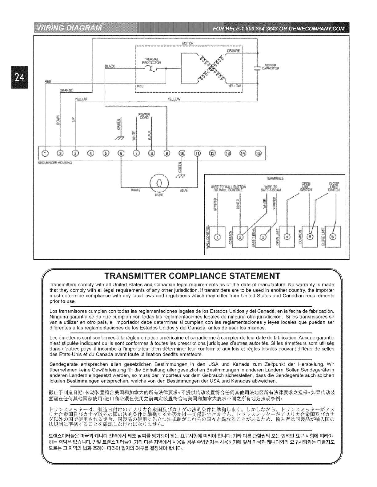
TRANSMITTER COMPLIANCE STATEMENT
Transmitters comply with all United States and Canadian legal requirements as of the date of manufacture. No warranty is made
that they comply with all legal requirements of any other jurisdiction. If transmitters are to be used in another country, the importer
must determine compliance with any local laws and regulations which may differ from United States and Canadian requirements
prior to use.
Los transmisores cumplen con todas las reglamentaciones legales de los Estados Unidos y del Canada, en la fecha de fabricaci6n.
Ninguna garantJa se da que cumplan con todas las reglamentaciones legales de ninguna otra jurisdicci6n. SJlos transmJsores se
van a utiNzar en otto pais, el importador debe determinar si cumplen con las reglamentaciones y leyes locales que puedan ser
diferentes a las reglamentaciones de los Estados Unidos y del Canad& antes de usar los mismos.
Les emetteurs sont conformes a la reglementation am@icaine et canadienne a compter de leur date de fabrication. Aucune garantie
n'est stipulee indiquant qu'ils sont conformes a toutes les prescriptions juridiques d'autres autorites. Si les emetteurs sont utiNses
dans d'autres pays, il incombe a I'importateur d'en determiner leur conformite aux lois et regles locales pouvant diff@er de celles
des Etats-Unis et du Canada avant toute utilisation desdits emetteurs.
Sendeger_ite entsprechen allen gesetzlichen Bestimmungen in den USA und Kanada zum Zeitpunkt der Herstellung. Wir
Obernehmen keine Gew_hrleistung for die Einhaltung aller gesetzlichen Bestimmungen in anderen L_indern. Sollen Sendeger_ite in
anderen L_ndern eingesetzt werden, so muss der Importeur vor dem Gebrauch sichersteNen, dass die Sendeger_te auch solchen
Iokalen Bestimmungen entsprechen, welche von den Bestimmungen der USA und Kanadas abweichen.
A_nlE-I--_ ° nl_,Z[ttlL[q _011_,t;Ct1_MS_[_9_ISltOI_[L--o-?-.q&[Ott[[[_[Ot_LIE[. 21El-ct--_-__ _-_°1 _-_ _od p_¥,tf_o_l[q_[ot
........... 7-_-_ _x_ ,tfod_10tl_;tt nl_,_[_'tIL[EI--?-[£I,°,_t[gA_ E[_XI,_
Page 25
Prices on reverse
Precio en dorso
Prix sur oppose
GEI IE:
Garage Door Operator Accessories
Accesorios para abridores de garajes
Accessoires pour ouvre-porte de garage
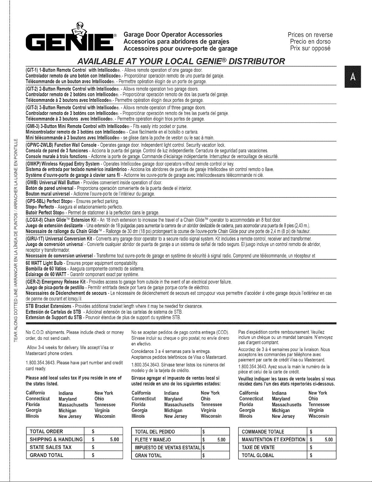
AVAILABLE AT YOUR LOCAL GENIE ¢ DISTRIBUTOR
(GIT-1)1-ButtonRemoteControlwithIntellicode®.-Allowsremoteoperationofonegaragedoor.
ControladorremotodeuricbotchconIntellicode®.-Proporcionaroperacionremotodeunopuertadelgaraje.
TelecommandedeunboutonavecIntellicode®.- Permettreoperationelogindeunportedegarage.
(GIT-2)2-ButtonRemoteControlwith Intellicode®.- Allowsremoteoperationtwogaragedoors.
Controladorremotode2boronsconIntellicode®.-ProporciGnaroperacionremotodedoslaspuertadelgaraje.
Telecommandea2 boutonsavecIntellicode®.-Permettreoperationelogindeuxportesdegarage.
(611"-3)3-ButtonRemoteControlwithIntellicode®.- Allowsremoteoperationofthreegaragedoors.
Controladorremotode3boronsconIntellicode®.- ProporciGnaroperacionremotodetreslaspuertadetgaraje.
Telecommandea3 boutonsavecIntellicode®.- Permettreoperationetogintriosportesdegarage.
(GMI.3)3-ButtonMiniRemoteControlwithIntellicode®-Fitseasilyintopocketorpurse.
Minicontroladorremotode3boronsconIntellicode®-Cavefacilmenteenelbolsilloo cartera.
Minitelecommandea3 boutonsavecIntellicode®- seglissedartslapochedevestonoulesacamain.
___ (GPWC-2WLB)FunctionWallConsole-Operatesgaragedoor.Independentlightcontrol.Securityvacationlock.
z Consoladeparedde3rune!ones-Accionalapuertadelgaraje.Controideluzindependiente.Cerraduradeseguridadparavacaciones.
Consolemuraleatroisfonctions-Actionneiaportedegarage.Commanded'eclairageindependante.Interrupteurdeverrouillagedesecurit&
uJZ (GWKP)WirelessKeypadEntrySystem-OperatesIntellicode®garagedooroperatorswithoutremotecontrolorkey.
_: Sistemadeentradaportecladohumor!coinalambrico-AccionalosabridoresdepuertasdegarajeIntellicode®sincontrolremotooIlave.
_ Systemed'ouvre-portedegaragea claviersansfil- Actionnelesouvre-portedegarageavecIntellicode®sanstelGcommandenict&
J
<, (GWB)UniversalWallButton-Providesconvenientinsideoperationofdoor.
_: Botchdepareduniversal-ProporcionaoperaciGnconvenientedelapuertadesdeeiinterior.
LU
z Boutonmuraluniversel-ActionneI'ouvre-portede!'inter!ourdugarage.
rj
_< (GPS-SBL)PerfectStop®-Ensuresperfectparking.
_: Stop®Perfecto-Aseguraelestacionamientoperfecto.
8utoirPerfectStop®-Permetdestationneraiaperfectiondansiegarage.
o (LCGXo8)ChainGlideTM ExtensionKit- An18inchextensiontoincreasethetravelofaChainGlideTM operatortoaccommodatean8footdoor.
Z
JuegodeextensiGndeslizante- Unaextensionde18pulgadasparaaumentarlacarreradeunabridordeslizabledecadena,paraacomodarunapuertade8pies(2,43m.).
uJ NecessairederallongeduChainGlide;M-Rallongede30dm(18pc)prolongeantlacoursedeIbuvre-porteChainGlidepouruneportede2,4m(8pi)dehauteur.
dD
w< (GIRU-1T)UniversalConversionKit- Convertsanygaragedooroperatorto a secureradiosignalsystem.Kitincludesaremotecontrol,receiverandtransformer.
z Juegodeconversionuniversal-Conviertecualquierabridordepuertadegarajea unsistemadeserialderadioseguro.Eljuegoincluyeuncontrolremotodeabridor,
< receptorytransformador.
z Necessairedeconversionuniversel-Transformetoutouvre-portedegarageensystemedesecurit6asignalradio.ComprendunetelGcommande,unrecepteuret
LU
_: 60WATTLightBulb-Ensuresproperequipmentcompatability.
o< Bombillade60Vatios-Aseguracomponentecorrectodesistema.
z Eclairagede60WATT-Garantircomponantexactparsysteme.
<
_: (GER-2)EmergencyReleaseKit- Providesaccessto garagefromoutsideintheeventofanelectricalpowerfailure.
Juegodepica-portedepestillo-Permitirentrtadadesdeporfueradegarajeporquecortedeelectrico.
z NecessairesdeDeclenchementdesecours- Lenecessairededeclenchementdesecoursestco%upourvouspermettred'accederavotregaragedepuisI'exterieurencas
J
depannedecourantetIorsqu'il.
___ STBBracketExtensions-Providesadditionalbracketlengthwhereit maybeneededforclearance.
o ExttesibndeCartelasdeSTB -AdicionalextensiondelascartelasdesistemadeSTB.
co ExtensiondeSupportduSTB- PourvoiretenduedeplusdesupportdusystemeSTB.
Z
o
<
No C.O.D.shipments.Please includecheck or money
order, donot send cash.
Allow3-4 weeksfor delivery.We acceptVisaor
Mastercardphone orders.
1.800.354.3643.Please havepart numberand credit
card ready.
Please add local sales tax ifyou reside in one of
the states listed.
California indiana New York California indiana New York California indiana New York
Connecticut Maryland Ohio Connecticut Maryland Ohio Connecticut Maryland Ohio
Florida Massachusetts Tennessee Florida Massachusetts Tennessee Florida Massachusetts Tennessee
Georgia Michigan Virginia Georgia Michigan Virginia Georgia Michigan Virginia
Illinois New Jersey Wisconsin Illinois New Jersey Wisconsin Illinois NewJersey Wisconsin
Nose aceptanpedidosde pagocontraentrega (COD).
Sirvaseincluirsu cheque ogiro postal;no enviedinero
enefectivo.
Concedanos3a 4 semanasparala entrega.
Aceptamospod!dostelefGnicosde Visa oMastercard.
1.800.354.3643.Sirvasetenorlistoslos nOmerosdel
modeloy dela tarjetade credito.
8irvase agregar el impuestodeventaslocalsi
usted reside enuric de los siguientes estados:
Pasd_expeditioncontreremboursement.Veuillez
inclureun chequeou unmandatbancaire.N'envoyez
pasd_argentcomptant.
Accordezde 3 a 4 semainespourla livraison.Nous
acceptonslescommandospartelephoneavec
paiementparcarte de creditVisaou Mastercard.
1.800.354.3843.Ayezsous tamainle numerodela
pieceet celuide la carte decredit.
Veuillez indiquerlostaxes devente localessi vous
residezdartsI'un des_tats repertoriesci-dessous,
II
TOTAL ORDER $
SHIPPING & HANDLING $ &O0
STATE SALES TAX $
GRAND TOTAL $
TOTALDEL PEDIDO $
FLETEY MANEJO $ 5.00
IMPUESTODE VENTAS ESTATAL $
GRAN TOTAL $
COMMANDETOTALE $
MANUTENTIONET EXPEDITION $ 5.00
TAXE DEVENTE $
TOTALGLOBAL $
Page 26

II
MODEL
MODELO
MODELE
DeluxeRemoteControlwithtntellicode®
GIT-I
iControladorremotodelujoconIntellicode®
iTel6commandedeluxeavecIntellicode®
i2-ButtonRemoteControlwithIntellicode®
iControladorremotode2funcionesconIntellicode®
GIT-2
iTel6commandea2fonctionsavecIntellicode®
i3-ButtonRemoteControlwithIntellicode®
GIT-3
iControladorremotode3funcionesconIntellicode®
iTel6commandea3fonctionsavecIntellicode®
i3-ButtonMiniRemoteControlwithtntellicode®
Minicontroladorremotede3funciones
GMI-3
iconIntellicode®
Minitel6commandea3fonctionsavectntellicode®
LightedWallConsole
GPWC-2WLB
iCons@deparedencender
Consolemuraleavececlairage
iWirelessKeypadEntrySystem
GWKP
iSistemadeentradapottecladonumericoinalambrico
Systemed'ouvre-portedegarageaclaviersansfil
UniversalWallButton(unlit)
GWB
Bot6ndepareduniversal(unlit)
aoutonmuraluniversel(unlit)
PerfectStop®
GPS-5BL
iStopPerfecto®
ButoirPerfectStop®
ChainGlideT_'_ExtensionKit
LCGX-8
Juegodeextensi6ndecadenadeslizable
N@essairedeprolongementdu
coulisseau
UniversalConversionKit
GIRU-IT
jJuegodeconversi6nuniversal
Necessairedeconversionuniversel
i60WATTLightBulb
LIGHTBULB
Bombillade60Vatios
Eclairagede60WATT
DESCRIPTION
DESCRIPCION
DESCRIPTION
Garage Door Operator Accessories Order Form
Formulario de pedido de accesorios para abridores de puertas de garaje
Formulaire de commande des accessoires pour ouvre-porte de garage
PRODUCTCODE PRICE(US$)* QTY, TOTAL
CODIGO PRECIO*CANTIDADTOTAL
CODEDUPRODUITPRIX($US)* QTE TOTAL
33069R $34.95
33069S $44.95
33069T $49.95
34909R $39.95
34292R $34.95
35282R $49.95
34960R $ 4.95
34964R $ 4.95
00001085 $34.95
33154R $49.95
26210A.S $2,95
Prices subject to change without notice I
El precio est& sujeto a cambios sin aviso I
Les prix, peuvent subir des modifications I
sans preavls j
I
I
LU
-q,
Z
5
CL
Z
LU
LU
Z
©
<,
o_
LU
I
(J
<
<
GO
O
F-
Z
CL
LIJ
C_
<
LU
Z
z
w
02
<
o
z
<
if2
_<
w
Z
123
ku
o
C3
©
7
s
<
a2
<
kU
EmergencyReleaseKit
jJuegodepica-portedepestillo
GER-2 34963R $29.95
Necessairesded'clenchementdesecours
STBBracketExtensions
Extensi6ndeCartelasdeSTB 34439R.S $4.95
ExtensionduSupportdeSTB
SHiPORDERTO:
NAME/ NOMBRE/NOM
ENVIARMERCANCIA
CON:
ADDRESS/ DIRECCI6N/ ADRESSE
CITY/ ClUDAD/VILLE
EXPCDIERMARCHANDISE
POUR:
STATE/ ESTADO/ eTAT ZIP/ CoDIGOPOSTAL/ CODEPOSTAL
MAIL ORDER
FORM TO:
The Genie Company
22790 Lake Park Blvd.
Alliance, Ohio 44601
Page 27

TheGenie CompanyProfessionalAccess Systems
LiMiTED WARRANTY
What is covered:Any defect in materialand productworkmanshipfrom personal,
normal householduse inaccordancewith the Owner's Manual.
For how long:
H2000C-1Series- 3 years on Motor,and 1year on all other parts.
350L- 1 Series- 3 yearson Motor,and 1year on allother parts.
350L- 1XSeries - 5years on Motor,and 2 year on all otherparts.
350L- 2 Series - 5 yearson Motor,and 2 yearson all other parts.
350L-2WKCSeries- Lifetime*onMotor, 2 years on all other parts.
350L-2CSeries- 5 yearson Motor,2 yearson allother parts.
350L-2WKSeries- 5 yearson Motor,2 years on all other parts.
500MLSeries - 5 years on Motor, and 3 yearson all other parts.
700MLSeries - Lifetime*on Motor,3 years on all otherparts.
*Lifetimewarranty- warrantedforas longas you own your home.
Who gets the warranty: This warrantyis limited tothe consumer whooriginally
purchasedthe product.
Geographic scope: This warrantyappliesonly to Genieproducts purchased in
the UnitedStates and Canada.
Whatwe will do: Ifyour Genieproductis defective, we will repair it or, at our
option,replaceit at no chargeto you. Ifwe repairyour Genie product,we may use
new or reconditionedreplacementparts. Ifwe chooseto replaceyour Genie
product,we may replace it with a newor reconditionedoneof thesameor
similardesign.
Limitations:
IMPLIEDWARRANTIES, INCLUDINGTHOSEOF FITNESSFORA PARTICULAR
PURPOSEANDMERCHANTABILITY(ANUNWRITTENWARRANTYTHATTHE
PRODUCTIS FIT FORORDINARYUSE),ARE LIMITEDTOONEYEAR FROM
THE DATEOF PURCHASE.GENIEWILL NOTPAY FOR: LOSS OF TIME;
INCONVENIENCE;LOSS OFUSE OFYOUR GENIEPRODUCTORPROPERTY
DAMAGECAUSED BYYOUR GENIEPRODUCTORITS FAILURETO WORK;
ANY SPECIAL,INCIDENTALORCONSEQUENTIALDAMAGES;ORANY
DAMAGESRESULTINGFROMMISUSEOR MODIFICATIONOFYOUR GENIE
PRODUCT.
Some statesand provincesdo not allow limitationson howlongan implied
warrantylasts orthe exclusionofincidentalor consequentialdamages,so the
aboveexclusionsmay notapply to you.
How to get warranty service: Toobtainwarrantyservicefor your Genie
product,you must provideproofof the dateand placeof purchaseof the product.
1.Do-it-Yourself-Service.Call the Genie ConsumerConnectiontollfree at
1.800.354.3643tospeak in personto a trained Genierepresentativefor
requiredpartsfor do-it-yourselfrepairs.Trainedservice representativesare
availableMonday-Friday,8:00 a.m.- 11:00p.m.,EasternTime,andon Saturday,
11:00p.m.to 8:00 p.m., EasternTime (subjectto holidays)Youmay alsoget the
informationyou need at www.geniecompany.com.
2.Service FromAuthorized Dealers.
Youalso mayobtainwarrantyservicefrom Genieauthorizeddealerslisted inthe
encloseddirectory.Pleasenotethat this listingissubject to changewithout
notice;we recommendthat you verifythe dealer'sstatusby calling the Genie
ConsumerConnectionat 1.800.654.3643or by visiting www.geniecompany.com
beforereachingany agreementon service.Ifwarrantyservice is providedby an
authorizeddealer, Geniewill provideall requiredparts underwarranty at no
chargeto you, but the dealers are independentbusinesspeopleand mayrender
a benchor servicecallchargefor their services. Geniewill not reimburseyou or
otherwiseberesponsiblefor thosecharges.
We suggestthat you retain your original packingmaterialin the eventyou need
toship yourGenie product.Be sureto includeyour name,address, telephone
number,proofof date andplace d purchaseand a descriptionofthe operating
problem.After repairingor, at our option,replacing,your Genie product,wewill
shipit to yourhome at no cost to youfor partsand labor, butyouwill have to pay
a minimumof$8.00 for shipping andhandlingcharges.
Yourchoiceof either one of the above-describedserviceoptions isyour
exclusiveremedy underthis warranty.
What this warranty does not cover: This warrantydoesnot cover batteries
(whichare consideredreplaceableparts),installation,commercialuse,defects
resultingfrom accidents,damagewhile in transit toour servicelocationor damage
resultingfrom alterations,misuseor abuse, lackd propermaintenance,
unauthorizedrepair or modificationof the product,affixingofany attachment not
providedwith the product, programmingof the RemoteControlDevices,
Safe-T-Beam®adjustmentlcleaning,staplesthrough wiring, pinched or broken
wires, Carriagedisengaged,Force Controladjustments, door out ofbalance,
broken springsor cables, poweroutages, useof extensioncords, missingor
damaged parts ondiscounted, clearanced,final sale or taped cartons, phantom
operations(labor is not coveredif Opener is functioning properlywhiletechnician
is in garage),fire,flood, or actsof God, orother failure tofollow the Owner's
Manual.
This warrantyis the only one we will give on your Genie product, and itsets
forth all our responsibilities regarding your Genie product. There are no other
express warranties.
State and province rights: Thiswarrantygivesyou specificlegalrights,andyou
may alsohave otherrightswhichvary from state tostate and provinceto province.
FORANSWERS:CALL 1.800.354.3643
FILL THIS IN AT TIME OF INSTALLATION FOR YOUR OWN RECORDS, SO THAT IT WILL
Date Purchased /
Operator Model
Remote Control Model
Dealer Name
Dealer Address
City
State
Zip
Visit Our Website at: www.geniecompany.com
Manufactured under one or more of the following U.S. patents:
3,898,582 4,041,259 4,048,630 4,064,487 4,103,238 5,222,403
Other Patents applied for.
CORRESPONDENCE WITH FACTORY MUST INCLUDE DATE / MFG. NO.
(LOCATED UNDER LENS OF POWER HEAD)
BE AVAILABLE IF YOU EVER NEED TO CALL US.
Serial Number / /
SAVETHESE INSTRUCTIONS
 Loading...