

Page 1

Operator’s Manual
Serial number range
GTH-4518 ER
GTH-4020 ER
GTH-6025 ER
From s/n: 18004
To s/n: 20111
From s/n: 19127
To s/n: 20117
From s/n: 13309
To s/n: 19308
With Maintenance
Information
First Edition
Third Printing
Part No. 57.0009.0404
Page 2

Operator’s Manual First Edition - Third Printing
Important
Read, understand and obey these safety rules
and operating instructions before operating the
machine. Only trained and qualified personnel
shall be authorized to operate the machine.
This manual shall be kept with the machine at
all times.
For any further information, please call
Terexlift.
Contact us:
ZONA INDUSTRIALE I-06019 UMBERTIDE
(PG) - ITALY
Telephone +39 075 941811 - Telefax +39 075
9415382
Technical Assistance Service
Telephone: +39 075 9418129
+39 075 9418171
e-mail: im.service@terexlift.it
Contents
Introduction ..........................................Page 3
Machine Identification ..........................Page 5
Symbols Used On The Machine ..........Page 7
Labels And Plates Applied On The
Machine ...............................................Page 9
Safety Precautions ..............................Page 15
Description Of The Main Components ...Page 23
Controls And Instruments ....................Page 25
Inspections ..........................................Page 55
Operating Instructions .........................Page 61
Transporting The Machine...................Page 75
Maintenance ........................................Page 79
Faults And Troubleshooting.................Page 113
Optional Attachments ..........................Page 129
Specifications ......................................Page 141
Load Charts .........................................Page 143
Diagrams and Schemes .....................Page 161
Warranty ..............................................Page 183
First Edition: Third Printing, February 2009
Copyright © 2006 TEREXLIFT srl - All rights
reserved.
Produced by:
TEREXLIFT Technical Literature Dept.
Umbertide (PG) Italy
2 GTH-4518ER - GTH-4020ER - GTH-6025ER Part No. 57.0009.0404
Page 3

Symbols
Operator’s ManualFirst Edition - Third Printing
Introduction
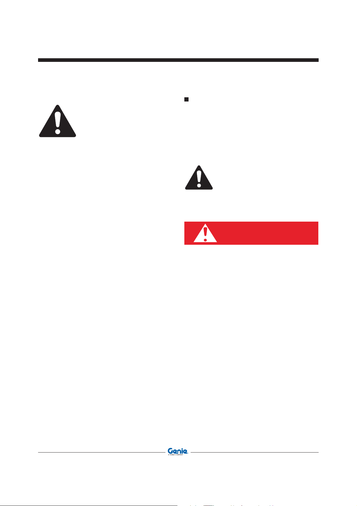
Safety alert symbol: used to
alert you to potential personal
injury hazards. Obey all safety
messages that follow this
symbol to avoid possible
injury or death
DANGER
WARNING
CAUTION
NOTICE
PROTECT THE
ENVIRONMENT
Red: indicates a hazardous
situation which, if not avoided,
will result in death or serious
injury.
Orange: indicates a hazardous
situation which, if not avoided,
could result in death or serious
injury.
Yellow : indicates a hazardous
situation which, if not avoided,
could result in minor or
moderate injury.
Blue: indicates a property
damage message.
Green: used to draw the
attention to important
information on environment
protection.
Part No. 57.0009.0404 GTH-4518ER - GTH-4020ER - GTH-6025ER 3
Page 4

Operator’s Manual First Edition - Third Printing
Intentionally blank page
4 GTH-4518ER - GTH-4020ER - GTH-6025ER Part No. 57.0009.0404
Page 5

Check that the operator handbook refers to the
delivered machine.
MODEL AND TYPE
Handler with telescopic boom. Models:
GTH-4518ER - GTH-4020ER - GTH-6025ER
MANUFACTURER
TEREXLIFT srl
Zona Industriale - I-06019 UMBERTIDE (PG) ITALY
Enrolled in the register of companies at the Court of
Perugia under no. 4823
C.C.I.A.A. 102886
Fiscal Code/V.A.T. no. 00249210543
APPLICABLE STANDARDS
For the operator’s safety, the following standards were
obeyed during the risk assessment of the handler
fitted with telescopic boom norme:
Directive Title
98/37/CE Machinery Directive
89/336/CEE Electromagnetic compatibility
2000/14/CE Environment Acoustic Emissions
Standard Title
ISO 2330:1995 Fork-lift trucks - Fork arms - Technical
characteristics and testing.ISO 3287:
1999 Powered industrial trucks -
Symbols for operator controls.
Operator’s ManualFirst Edition - Third Printing
Machine Identification
MACHINE IDENTIFICATION PLATES
The following data plates are applied on the
machine:
Machine data plate
The identification plate contains the main identification
data of the machine like model, serial number and
year of manufacture.
On machines destined for the Italian market, the data
plate is installed in the driving cab, on the right, and
is well-visible when the door is opened.
On the machines destined for foreign markets, the
data plate is applied on the front right side of the
chassis.
Road traffic data plate
The road traffic data plate is installed on the front
right side of the chassis (only on machines destined
for the Italian market).
This plate shows the road traffic related data and the
weights of the specific machine model.
ROPS-FOPS cab type-approval plate
The ROPS - FOPS type-approval plate is located
inside the driving cab above the rear glass.
Fork data plate
Placed on the left side of the fork frame.
This plate shows the identification data of fork such
as model, serial number, year of manufacture, weight,
nominal payload, centre of the load and model of the
machine on which the forks are installed.
ISO 3449:1992 Earth-moving machinery - Falling-
object protective structures -
Laboratory tests and performance
requirements.
EN 13510: 2002 Earth-moving machinery - Roll-over
protective structures - Laboratory tests
and performance requirements.
EN 13059:2002 Safety of Industrial trucks- Test
methods for measuring vibration
Part No. 57.0009.0404 GTH-4518ER - GTH-4020ER - GTH-6025ER 5
Page 6

Operator’s Manual First Edition - Third Printing
Machine Identification
IDENTIFICATION PLATES OF THE MAIN
CE MARKING
This machine fulfils the safety requirements of
the Machinery Directive.The conformity has been
certified and the placing of the CE marking on the
machine demonstrates compliance with the regulatory
requirements.
The CE marking is placed directly on the identification
plate of the machine.
CHASSIS SERIAL NUMBER
The chassis serial number is punched on the front
left part of the chassis side member.
PARTS
The plates of the main components, not directly
manufactured by TEREXLIFT srl (for instance,
engines, pumps, etc.), are located where originally
applied by the manufacturers.
HOW TO READ
YOUR SERIAL
NUMBER
Chassis serial number
(The chassis serial number is punched on the front right
part of the chassis side member)
GTH 4518 P 07 17882
MODEL
ENGINE
TYPE
YEAR OF
MANIFACTURER
Machine data plate
(On machines destined for the Italian market, the machine data plate is
installed in the driving cab, on the right, and is well-visible when the door
is opened. On the machines destined for foreign markets, the data plate
is applied on the front right side of the chassis)
SERIAL
NUMBER
6 GTH-4518ER - GTH-4020ER - GTH-6025ER Part No. 57.0009.0404
Page 7

Not Active
Symbols Used On The Machine
P
Parking Brake High Beam Turn Signals
Low Beam
Operator’s ManualFirst Edition - Third Printing
Turret Rotation
Lock
Turret Aligned
Extend Outrigger Raise Outrigger
Fuel Level
Brake Pressure
General Warning
Differential Lock 2° speed engaged 1° speed engaged Machine Sway Retract Outrigger
Glow Plugs
Preheatinh Service
Hydraulic Oil Filter
Shift-on-Fly
Lower Outrigger
Air Filter
Comando luci
retronebbia
Right Machine
Sway Left Machine Sway
Engine Coolant
Temperature
Not Active
Emergency Pump
Battery Charge
Water in Fuel
Hazard Warning
Lights
Turret Rotation
Unlock
Engine Oil
Pressure
Hydraulic Oil Level
Heating Cab Fan
Job-site mode
Man-Platform
Road Transfer Steering Mode
Part No. 57.0009.0404 GTH-4518ER - GTH-4020ER - GTH-6025ER 7
Page 8

Operator’s Manual First Edition - Third Printing
Symbols Used On The Machine
HAZARD PICTORIAL DESCRIPTIONS
Electrocution
Hazard
No riders.
Read the operator's
manual.
Crush Hazard
Maintain required
clearance.
Burn Hazard
Support boom
when performing
maintenance.
Keep away from
moving parts.
Falling Object
Hazard
Allow system to
cool.
Crush Hazard
Crush Hazard
No people under
load.
Explosion/Burn
Hazard
Burn Hazard
Keep clear of
moving parts.
Fall Hazard
No smoking. No
open flame.
Allow surfaces to
cool.
Allow compartment
access
Crush Hazard
8 GTH-4518ER - GTH-4020ER - GTH-6025ER Part No. 57.0009.0404
Keep clear of
moving outriggers.
Tip-over Hazard
Crush Hazard
Keep away from
obstacles
Page 9

Operator’s ManualFirst Edition - Third Printing
Labels And Plates Applied On The Machine
26
22
10
A
18
29
8
4
34
13
5
14
3
B
5
18
12
25
2
1
11
9
15
6
32
14
16
26
33
25
3
27
19
13
9
5
14
C
25
20
28
25
30
24
15
31
13
14
4
21
7
19
5
9
14
3
33
3
14
13
9
Part No. 57.0009.0404 GTH-4518ER - GTH-4020ER - GTH-6025ER 9
Page 10

Operator’s Manual First Edition - Third Printing
Labels And Plates Applied On The Machine
Use the pictures on these pages to verify that all decals are legible and in place.
Use the pictures on these pages to verify that all decals are legible and in place.
The following chart shows quantities and description too.
The following chart shows quantities and description too.
Ref. Decal Code Description Qt.
SAFETY PIN
WORKING POSITION
1 09.4618.0791 Safety pin operation 1
STORAGE POSITION
09.4618.0791
2 09.4618.0784
09.4618.0547
3
P= 5.5 bar
80 psi
09.4618.0754
The capacity of the truck and attachment
combination shall be complied with.
Tyre inflat. P=5,5bar / 80psi
GTH-4518 ER / GTH4020 ER
Tyre inflat. P=8bar/116psi GTH-6025 ER
4 09.4618.0918 Falling Object Hazard 3
09.4618.0918
5 09.4618.0919 Crush Hazard 4
09.4618.0919
09.4616.0041
Sound power level: 103 db for GTH4518ER and GTH-4020ER
6
103
09.4616.0041
09.4618.0260
Sound power level:105 db for GTH6025ER
1
4
1
7 09.4618.0920 Compartment Access 1
Kg 4000
8
Kg 4500
Kg 6000
09.4618.0920
09.4616.0040
09.4618.0373
09.4618.0757
Max Capacity
Kg 4000 (GTH-4020 ER)
Kg 4500 (GTH-4518 ER)
Kg 6000 (GTH-6025 ER)
1
10 GTH-4518ER - GTH-4020ER - GTH-6025ER Part No. 57.0009.0404
Page 11
Operator’s ManualFirst Edition - Third Printing
a
o
e
e
D
a
z
u
Labels And Plates Applied On The Machine
Ref. Decal Code Description Qt.
09.4618.1048
9
P max al suolo
P max on the ground
NOTICE
6.3 kg/cm
09.4618.0989
2
09.4618.1049
10 09.4618.0776
09.4618.0776
GUIDA RAPIDA PER L’USO
4518-4020-
6025
3
2
4
4
USO DELLA LEVA DI COMANDO
Premere sempre il pulsante di comando intenzionale , prim
eseguire un comando.
LEVA DESTRA
•
Abbassamento/solevamento del braccio: azionare la leva in direzi
-
•
Brandeggio indietro/avanti dell’attrezzo terminale: azionar
leva in direzione -
• Richiamo/sfilo del braccio telescopico: azionare il pulsante
direzione - senza movimentare la leva
• Blocco/sblocco attrezzi: premere il pulsante ed azionare la l
in direzione -
LEVA SINISTRA
•
Rotazione torretta: azionare la leva in direzione -
CONFERMA DELL’ATTREZZO IN USO PER L’ABILITAZIONE
LIMITATORE DI CARICO
Alla messa in moto della macchina il limitatore di carico esegue
check progressivo.
Dopo circa 20 secondi appare la data ed il modello della macchin
poco dopo, la prima pagina con selezionato l’ultimo attrezzo utiliz
o il nuovo attrezzo dotato di riconoscimento elettrico.
Qualora sia stato installato un attrezzo “meccanico” si dovrà eseg
la ricerca manuale. Premere INDEX fino a quando, nella casella
display, non comparirà la lettera corrispondente all’attrezzo in uso.
Premere ENTER per confermare l’attrezzo.
La macchina è pronta per l’uso.
09.4618.0769
09.4618.0770 Quick guide and Control lever decal
11
AVVIAMENTO DELLA MACCHINA
• Posizionare il selettore marce ed il cambio meccanico in folle.
• Inserire il freno di stazionamento e controllare che la spia sia
accesa.
• Avviare il motore ruotando
il commutatore di avviamento
in posizione ed attendere
che la spia sul cruscotto
si spenga. Con la spia spenta
ruotare il commutatore in
posizione rilasciandolo
non appena il motore verrà
avviato.
• Qualora, dopo circa 20 secondi, l’avviamento del motore non avesse
luogo, rilasciare la chiave ed attendere circa due minuti prima di
tentare un nuovo avviamento.
ATTENZIONE
È vietato utilizzare la macchina e gli accessori senza prima aver
letto e compreso le norme di utilizzo e di sicurezza contenute nel
manuale di istruzioni. Il mancato rispetto delle norme di utilizzo
e di sicurezza può causare grave pericolo all’operatore e a terzi.
Le istruzioni sono consegnate con la macchina e copie
aggiuntive possono esere richieste al rivenditore o direttamente
a Terexlift.
L’operatore è responsabile del rispetto delle norme sopra
riportate.
Non sollevare carichi se la macchina appoggia su terreno
instabile o inclinato. Non sollevare mai carichi superiori a quelli
indicati in tabella. Non sono ammesse manovre di sollevamento
con macchina in movimento.
Prima di abbandonare il posto di manovra:
- abbassare eventuali carichi sospesi
- portare in posizione di riposo gli organi di comando del braccio
- posizionare la leva marcia avanti-indietro in folle, inserire il
freno a mano e arrestare il motore.
Norme per l’utilizzo di macchine dotate di stabilizzatori.
È vietato utilizzare gli stabilizzatori se il carico è già sollevato: gli
stabilizzatori servono solamente ad aumentare la stabilità della
macchina; l’uso scorretto degli stabilizzatori può causare il
ribaltamento della macchina.
Un’apposita spia sul cruscotto indica che gli stabilizzatori sono
abbassati: accertarsi che la spia sia accesa.
Prima di sollevare il carico, livellare la macchina controllando
l’apposito indicatore di livello.
12 09.4618.0921
Label - Stabilizer Max Pres. GTH-6025ER
Label - Stabilizer Max Pres.
GTH-4518ER GTH-4020ER
Label - Upper Door Internal Unlock
System
Label - Use limits close to electric power
lines
4
4
1
1
1
09.4618.0921
13 09.4618.0933 Crush Hazard 4
09.4618.0933
14 09.4618.0922 Crush Hazard 7
09.4618.0922
15
16
Ref. Descrizione
F1G F4G
17 09.4618.xxxx Label - Engine Fuses & Relays Board 1
Part No. 57.0009.0404 GTH-4518ER - GTH-4020ER - GTH-6025ER 11
F2G F3G
K01
K01 Glow Plugs Preheating
K02 Starter Enabling Switch
K04
K02
K04 Engine Stop
Ref. Descrizione
F1G Starter Enabling Switch
F5G
F2G Instruments Panel
F3G Cabin Fuses Board
F4G Glow Plugs
F5G Fuel Pump
09.4618.0807
09.4618.0243
09.4618.0241
Cosmetic - GENIE Logo in WHITE
2
1
Page 12
Operator’s Manual First Edition - Third Printing
Labels And Plates Applied On The Machine
Ref. Decal Code Description Qt.
GTH-4518 ER
09.4618.0824
09.4618.0825
Cosmetic - Genie GTH-4518 ER
2
2
18
19
GTH-4020 ER
GTH-6025 ER
09.4618.0826
09.4618.0827
09.4618.0828
09.4618.0829
Cosmetic - Genie GTH-4020 ER
Cosmetic - Genie GTH-6025 ER
20 09.4618.0923 Burn Hazard 2
09.4618.0923
21 09.4618.0924 Burn/Explosion Hazard 1
09.4618.0924
22 09.4618.0925 Crush Hazard 1
09.4618.0925
23 09.4618.0926 No Riders 1
09.4618.0926
2
2
2
2
24 09.4618.0927 Burn Hazard 1
09.4618.0927
25 09.4618.0916 Lift Point 6
09.4618.0916
26 09.4618.0917 Diesel Fuel Cap 1
09.4618.0917
27 09.4618.0928 Hydraulic Oil 2
09.4618.0928
12 GTH-4518ER - GTH-4020ER - GTH-6025ER Part No. 57.0009.0404
Page 13
Operator’s ManualFirst Edition - Third Printing
Labels And Plates Applied On The Machine
Ref. Decal Code Description Qt.
INSTRUCTIONS
Operate the levers only in an emergency and with the Diesel
engine stopped:
1. press the red emergency stop button in the cab
2. hold the button of the emergency pimp, on one side of the
machine, pressed down
3. operate the levers according to the following sequence:
a) Boom in (Lever 1 towards A)
b) Boom down (Lever 2 towards A)
The lever movements correspond to the following commands
A Boom Extension
Lever 1
B Boom Retraction
A Boom Lifting
Lever 2
B Boom Lowering
A Forks Upwards
Lever 3
B Forks Downwards
A Attachment Locking
Lever 4
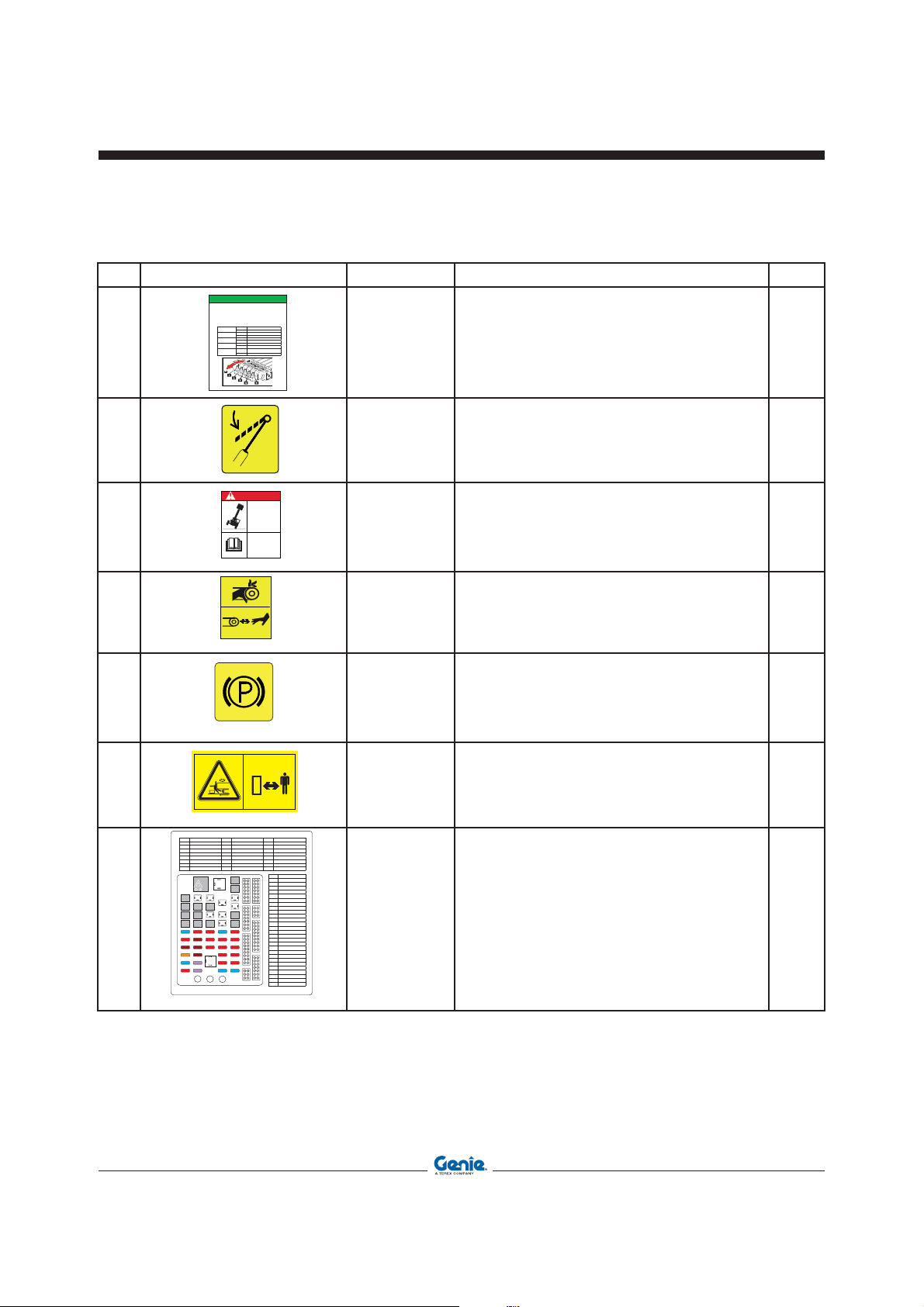
28 09.4618.1132 Label - Manual Controls Instructions 1
29 09.4618.1001 Label - Maintenance Collar 1
30 09.4618.1122 Manual Controls Danger 1
B Attachment Unlocking
A
Lever 5
B Turntable rotated clockwise
DANGER
Turntable rotated counterclockwise
09.4618.1001
Tip-over Hazard
Incorrect
emergency
lowering sequence
will result in
machine tip-over
Read, understand
and obey the
instructions below or
in the
Operator’s Manual
before lowering
09.4618.1132
09.4618.1122
31 09.4618.0986 Crush Hazard 1
09.4618.0986
32 09.4618.1028 Label - Parking Brake 1
09.4618.1028
33 09.4618.1120 Crush Hazard 2
09.4618.1120
Ref. Circuit Ref. Circuit Ref. Circuit
K1 High Beam K9 Transmission Disconnected K17 Optional
K2 Low Beam K10 Transmission Disconnected K18 Outriggers
K3 Horn K11 Start-Up Enabling Command K19 Overload Warning System
K4 Speed Switch Power Supply K12 Optional K20 High Boom
K5 Optional K13 Optional K21 Tilt/Ext. Exchange Movements
K6 Optional K14 Outriggers K22 Optional
K7 Forward Speed K15 Optional K23 Intermittence
K8 Reverse Speed K16 Optional K24 Timer
K23
K24
K16 K15K5K17
K8
K7
K1
K11
K20K12
K10
K9
K13
K2
K4
34 09.4618.xxxx Label -Cabin Fuses & Relays Board 1
F6
F5
F4
F3
F2
F1
K3
F15
F12
F14
F11
F13
F10
F9
RELE’
F8
F7
J3 J2 J1
F21
F20
F19
F18
2
F17
F16
.feR Circuit
F1 Front Wiper
K19
F2 Heating
F3 Stop Light Micro-Switch
K18
F4 Rear Wiper
F5 Hydraulic Activation
F6 Low Beam
F7 Right Position Lights
K6
F8 Instrument Lighting
F9
K21
K14
F27
F26
F25
F24
F23
F22
Indicator Lights Power Supply
F10 Lights Switch
F11 Flashing Beacon
F12 Stop Lights
F13 2° Hydr. Circuit Switch
F14 Speed Switch
F15 High Beam
F16 Emergency
F17 Lights And Flashing
F18 Outriggers Micro-Switch
F19 Work Mode Selector
F20 +12v On The Boom
F21 Horn
F22 Optional
F23 Cab Lights
F24 Emergency Stop
F25 Lmi Control
F26 Optional
F27 Work Lights
09.4618.1053
Part No. 57.0009.0404 GTH-4518ER - GTH-4020ER - GTH-6025ER 13
Page 14

Operator’s Manual First Edition - Third Printing
Labels and plates applied on the machine
Ref. Decal Code Description
ROPS-FOPS cab type-approval plate. This plate
A 09.4616.0100
TERE FT srl - ON N STR E - 06019 M ERT E PG - T
Tel. 075 941.811 Fa 075 941.5 .82 Tele 66106 T M
MOE O - MO E - MO E E - T P - MO E O
NNO OSTR ONE - E R OF M N F TRE - NNEE E F R TON
HR - ÑO E F R ÓN
B 09.4616.0112
MTR O - SER N. - N. E SER E - F .- ENT NR. - NO. E SER E
PESO M SS E NT. - M FRONT E E GHT - PO S M ESS E NT
. HS ST O. N. ST O - PESO M E E NTER OR
PESO M SS E POST. - M RER E E GHT - PO S M ESS E RR ERE
. HS ST H . N. ST O - PESO M E E POSTER OR
PESO TOT E - TOT E GHT - PO S TOT - . GESMTGE HT N. ST O
PESO TOT
MTR O MOTORE TERM O - ENGNE SER N. - N. MOTER THERM E
F R NR. ESE MOTOR - NO. E SER E MOTOR TERM O
OMOOG ONE
F R TO N T - M E N T
200
kgkg
kg
kg
shows the type-approval data of the driving cab
according to ROPS - FOPS regulations.
Machine data plate. The identification plate contains
the main identification data of the machine.
ASSIEME FORCHE-FORKS ASSY
GROUPE FOURCHES-GABELGROUPPE
JUNTO HORQUILLAS
MODELLO - TYPE - DƒSIGNATION
MODELL - MODELO
N¡ SERIE - SERIAL N¡-N¡ DE SERIE
- SERIEN N¡- N¡ DE BASTIDOR
ANNO DI COSTRUZIONE YEAR OF CONSTRUCTION ANNƒE DE CONSTRUCTION -
C 09.4616.0109
BAUJHAR - A„O DE CONSTRUCCIîN
MASSA - MASS - MASSE MASSE - MASA
CENTRO DI GRAVITË - CENTER OF
GRAVITY - CENTRE DE GRAVITƒ SCHWERPUNKT - CENTRO DE GRAVEDAD
PORTATA NOMINALE - PAY LOAD PORTEE NOMINALL - NENN
TRAGF€HIGKEIT - CARGA NOMINAL
CENTRO DI CARICO - LOAD CENTER CENTRE DE CHARGE - LASTPUNKT CENTRO DE CARGA
MODELLO MACCHINA - MACHINE MODEL DESOGNATION MACHINE - MASCHINEN MODELL
MODELO MçQUINA
Fork data plate. This plate shows the main data of
the fork installed on the machine.
14 GTH-4518ER - GTH-4020ER - GTH-6025ER Part No. 57.0009.0404
Page 15

Operator’s ManualFirst Edition - Third Printing
Safety precautions
DAMAGED MACHINE HAZARDS
• Do not use a damaged or defective machine.
• Do a thorough pre-operation inspection of the
machine and test all functions before each work
shift. Tag and remove from service a damaged
or defective machine.
• Make sure that all maintenance jobs have been
carried out as specified in this manual and the
appropriate service manual.
• Make sure that all decals are in place and
legible.
• Make sure that the operator’s is intact, legible
and placed in the special container located in the
machine.
PERSONAL INJURY HAZARDS
• Do not operate the machine in case of hydraulic
oil or air leak. Air or hydraulic oil leaks can
penetrate or burn the skin.
• Always operate the machine in a well ventilated
area to avoid carbon monoxide poisoning.
• Do not lower the boom if the area underneath is
not clear of personnel or obstructions.
SAFETY DEVICES
Several safety devices have been fitted to the
machine. They must never be tampered with or
removed.
Regularly check the efficiency of such devices.
In case of faults, stop working immediately and
proceed in replacing the defective device.
For the checking procedures, read chap.
"Maintenance"
MOMENT LIMITING SYSTEM
The moment limiting system has been developed to
help the operator to maintain the machine longitudinal
stability. Audible and visual messages are provided
when the limits of longitudinal stability are being
approached.
However this device cannot replace the experience
of the operator. It is up to the user to adopt the
necessary safety measures to work within the rated
limits of the machine.
Part No. 57.0009.0404 GTH-4518ER - GTH-4020ER - GTH-6025ER 15
Page 16
Operator’s Manual First Edition - Third Printing
Safety precautions
GENERAL REMARKS
Not observing the instructions
and safety rules in this manual
may result in death or serious
injury.
Do not operate the machine unless:
• You learn and practice the principles of safe
machine operation contained in this operator’s
manual.
1. Avoid hazardous situations. Read and
understand the safety instructions before
going on to the next chapter.
2. Always perform a pre-operation
inspection.
3. Always test the machine functions prior
to use.
4. Inspect the work place.
5. Only use the machine for the intended
application.
• Read, understand and obey the manufacturer’s
instructions and the safety rules, the safety and
operator’s manuals, and the decals applied on
the machine.
• Read, understand and obey the employer’s
safety rules and worksite regulations.
• Read, understand and obey the applicable
national regulations.
• Only trained personnel informed on the safety
rules can operate the machine.
Most accidents occurring while working, repairing or
maintaining machines, are caused by not complying
with the basic safety precautions.
Therefore, it is necessary to pay steady attention to
the potential hazards and the effects that may come
of operations carried out on the machine.
If you recognise hazardous situations, you can
prevent accidents!
DANGER
The instructions given in this handbook are the
ones established by TEREXLIFT. They do not
exclude other safe and most convenient ways
for the machine installation, operation and
maintenance that take into account the available
spaces and means.
If you decide to follow instructions other than those
given in this manual, you shall absolutely:
• be sure that the operations you are going to carry
out are not explicitly forbidden;
• be sure that the methods are safe, say, in
compliance with the rules and provisions given
in this section;
• be sure that the methods cannot damage the
machine directly or indirectly or make it unsafe;
• contact TEREXLIFT Assistance Service for
any suggestion and the necessary written
permission.
16 GTH-4518ER - GTH-4020ER - GTH-6025ER Part No. 57.0009.0404
Page 17

REQUISITES OF THE PERSONNEL IN CHARGE
Operator’s ManualFirst Edition - Third Printing
Safety precautions
Requisites of the MACHINE OPERATORS
The operators who use the machine regularly or
occasionally (i.e. for transport reasons) shall have
the following prerequisites:
health:
before and during any operation, operators shall
never take alcoholic beverages, medicines or other
substances that may alter their psycho-physical
conditions and, consequently, their working
abilities.
physical:
good eyesight, acute hearing, good co-ordination
and ability to carry out all required operations in
a safe way, according to the instructions of this
manual.
mental:
ability to understand and apply the enforced rules,
regulations and safety precautions. They shall be
careful and sensible for their own as well as for the
others’ safety and shall desire to carry out the work
correctly and in a responsible way.
emotional:
they shall keep calm and always be able to evaluate
their own physical and mental conditions.
training:
they shall read and be familiar with this handbook,
its enclosed graphs and diagrams, the identification
and hazard warning plates. They shall be skilled and
trained about the machine use.
Requisites of the SERVICEMEN
The personnel charged with the machine maintenance
shall be qualified, specialised in the maintenance
of telehandlers, and shall have the following
prerequisites:
physical:
good eyesight, acute hearing, good co-ordination
and ability to carry out all required maintenance
operations in a safe way, according to this manual.
mental:
ability to understand and apply the enforced rules,
regulations and safety precautions. They shall be
careful and sensible for their own as well as for the
others’ safety and shall desire to carry out the work
correctly and in a responsible way.
training:
they shall read and be familiar with this handbook,
its enclosed graphs and diagrams, the identification
and warning plates. They shall be skilled and trained
about the machine functioning.
NOTICE
From a technical point of view, the ordinary
maintenance of the machine is not a complex
intervention and can be carried out by the
machine operator, too, provided he has a basic
knowledge of mechanics.
The operator shall have a licence (or a driving
licence) when provided for by the laws enforced
in the country where the machine works. Please,
ask the competent bodies. In Italy the operator
must be at least 18 year old.
Part No. 57.0009.0404 GTH-4518ER - GTH-4020ER - GTH-6025ER 17
Page 18

Operator’s Manual First Edition - Third Printing
Safety precautions
OTHER DANGERS
WORKING CLOTHES
During work, but especially when maintaining or
repairing the machine, operators must wear suitable
protective clothing:
• Overalls or any other comfortable garments.
Operators should not wear clothes with large
sleeves or objects that can get stuck in moving
parts of the machine.
• Protective helmet.
• Protective gloves.
• Working shoes.
Use only type-approved working clothing in good
condition.
Hazards on the JOBSITE
Always take into account the features of the job site
where you are going to work:
• Always examine the working area and compare
it with the machine dimensions in the different
configurations.
DANGER
The machine is not electrically insulated and
does not provide protection from contact with
or proximity to electrical power lines.
Always keep at a minimum safe distance from
the telescopic boom and the lifted load. Electrical
hazards!
DEATH OR INJURY CAN RESULT FROM
CONTACTING ELECTRIC POWER LINES.
ALWAYS CONTACT THE ELECTRIC POWER LINES
OWNER. THE ELECTRIC POWER SHALL BE
DISCONNECTED OR THE POWER LINES MOVED
OR INSULATED BEFORE MACHINE OPERATIONS
BEGIN
POWER LINE VOLTAGE REQUIRED CLEARANCE
0 to 50kV 10ft 3.00m
50 to 200 kV 15 ft 4.60 m
200 to 350 kV 20 ft 6.10 m
350 to 500 kV 25 ft 7.62 m
500 to 750 kV 35 ft 10.67 m
750 to 1000 kV 45 ft 13.72 m
Personal PROTECTIVE EQUIPMENT
Under special working conditions, the following
personal protective equipment should be used:
• Breathing set (or dust mask).
• Ear-protectors or equivalent equipment.
• Goggles or facial masks.
• Keep away from the machine in case of contact
with energized power lines. Personnel on the
ground must never touch or operate the machine
until energized power lines are shut off.
DANGER
Use only type-approved protective equipment in
good condition.
18 GTH-4518ER - GTH-4020ER - GTH-6025ER Part No. 57.0009.0404
Do not at any time use the machine during a
storm.
Page 19

• The machine shall be parked on a ground
adequate to the maximum admissible payload. If
the subsoil collapses, the machine could tip over.
To avoid any risk of overturning, the following
precautions should be taken:
1. Ask your employer (site manager or manager
assistant) if there may be buried pipes, pits,
old tanks, cellar floor, dung yards, etc. under
the ground onto which the outriggers shall be
lowered.
2. A rough estimate of the ground consistency can be
done using the tables and picture in this page.
3. The resistance of the subsoil is in relation
to the ground type and geomorphological
characteristics.
Table 1 indicates the superficial pressure which
can be admitted under the outriggers of the
machine.
Type of ground,
geomorphological
features
loose, non-compact soil generally speaking,
loamy, peaty,pasty soil
rippable, soft ground
non-cohesive, well compact soil, sand, gravel
rippable
soil
Rocks, concrete, heavy
traffic paved roads
solid 1.0 0.1
semi-solid 2.0 0.2
hard 4.0 0.4
Admissible
superficial pressure
2
kg/cm
not solid;
special precautions
needed
2.0 0.2
above
10.0
N/mm
above
1.0
Table 1
2
Operator’s ManualFirst Edition - Third Printing
Safety precautions
WARNING
Make sure the machine (wheels and stabilisers)
rests on a firm ground to prevent hazardous unstable
conditions.
If the ground is not firm enough, position some
supporting planks under the stabilisers or the wheels.
These plates must grant a specific pressure of 1.2 to
1.5 kg/cm2 (800x800mm plates are sufficient).
• Look for the best route to the job site.
• When the machine is running, nobody can enter
its working range.
• While working, keep the working area in order.
Never leave objects scattered: they could hinder
the machine movements and represent a danger
for personnel.
• In presence of trenches, lower the outriggers at
a safe distance from the trench edge.
Bearing Capacity
Supporting
Surface
Overhang foot
The distance (a) from the foot of the overhang
shall be adequate to height (h) of the same
overhang.
If the ground fulfils the required conditions:
a : h = 1 : 1
(values with a grey background in table 1)
In the case of doubts:
a : h = 2 : 1
Part No. 57.0009.0404 GTH-4518ER - GTH-4020ER - GTH-6025ER 19
Page 20

Operator’s Manual First Edition - Third Printing
Safety precautions
OPERATION or MAINTENANCE hazards
Before any operation, following precautions should
be taken:
• First of all, make sure that the maintenance
interventions have been carried out with care
according to the established schedule.
WARNING
Set the machine to working configuration and sway
it. Use the special inclinometer to the right of the
driving place to check that the machine is level
before operating it.
• Ensure you have enough fuel to avoid a sudden
stop of the engine, especially during a crucial
manoeuvre.
• Clean instruments, data plates, lights and the
cab windscreen thoroughly.
• Check the correct functioning of all the safety
devices installed on the machine and in the job
site.
• In case of troubles or difficulties, inform the
foreman at once. Never start working under
unsafe conditions.
• Do not carry out any repair work in a makeshift
way to start working!
During work, and especially maintenance, always
pay the greatest attention:
• Do not walk or stop under raised loads or
machine parts supported by hydraulic cylinders
or ropes only.
• Keep the machine handholds and access steps
always clean from oil, grease or dirt to prevent
falls or slips.
• When entering/leaving the cab or other raised
parts, always face the machine; never turn the
back.
• When carrying out operations at hazardous
heights (over 1.5 meters from the ground), always
use approved fall restraint or fall arrest devices.
• Do not enter/leave the machine while it is
running.
• Do not leave the driving place when the machine
is running.
• Neither stop nor carry out interventions under
or between the machine wheels when engine
is running. When maintenance in this area is
required, stop the engine.
• Do not carry out maintenance or repair works
without a sufficient lighting.
• When using the machine lights, the beam should
be oriented in order not to blind the personnel at
work.
• Before applying voltage to electric cables or
components, check their connection and proper
functioning.
• Do not carry out interventions on electric
components with voltage over 48V.
• Do not connect wet plugs or sockets.
• Plates and hazard warning stickers shall never
be removed, hidden or become unreadable.
• Except for maintenance purposes, do not remove
safety devices, shields, protection cases, etc.
Should their removal be necessary, stop the
engine, remove them with the greatest care and
always remember to refit them before starting the
engine and using the machine again.
• Before any maintenance or repair work, stop the
engine and disconnect the batteries.
20 GTH-4518ER - GTH-4020ER - GTH-6025ER Part No. 57.0009.0404
Page 21

Operator’s ManualFirst Edition - Third Printing
WARNING
Safety precautions
• Do not lubricate, clean or adjust moving parts.
• Do not carry out operations manually when
specific tools are provided for this purpose.
• Avoid the use of tools in bad condition or use in
an improper way i.e. pliers instead of adjustable
wrenches, etc.
• Applying loads in different points of the attachment
holding plate is forbidden.
Any intervention on the hydraulic circuit must be
carried out by authorised personnel.
The hydraulic circuit of this machine is fitted
with pressure accumulators. You and others
could be seriously injured if accumulators are
not completely depressurised.
For this purpose, shut the engine down and step
on the brake pedal 8/10 times.
• Before carrying out operations on hydraulic
lines under pressure or disconnecting hydraulic
components, ensure the relevant line has been
previously depressurised and does not contain
any hot fluid.
• Do not empty catalytic mufflers or other vessels
containing burning materials without taking the
necessary precautions.
• After any maintenance or repair work, make
sure that no tool, cloth or other object has been
left within machine compartments, fitted with
moving parts, or where suction and cooling air
circulates.
• When working, do not give instructions or signs
to several people at the same time. Instructions
and signs must be given by one person only.
• Always pay due attention to the instructions given
by the foreman.
• Never distract the operator during working phases
or crucial manoeuvres.
• Do not call an operator suddenly, if
unnecessary.
• Do not frighten an operator or throw objects by
any means.
• After work, never leave the machine under
potentially dangerous conditions.
MACHINE OPERATION hazards
Absolutely avoid the following work situations:
• Do not handle loads beyond the maximum
capacity of the machine.
• Do not raise or extend the boom if the machine
is not on a firm, level surface.
• Do not operate the machine in strong wind. Do
not increase the surface area of the machine or
forked load exposed to the wind. Increasing the
area exposed to the wind will decrease machine
stability.
• Use extreme caution and slow speeds when the
machine is driven across uneven or unstable
grounds, slippery surfaces or near trenches or
drop-offs.
• Limit travel speed according to ground conditions,
slopes, presence of personnel or other factors
which may cause collision.
• Do not place or attach overhanging loads to any
part of the machine.
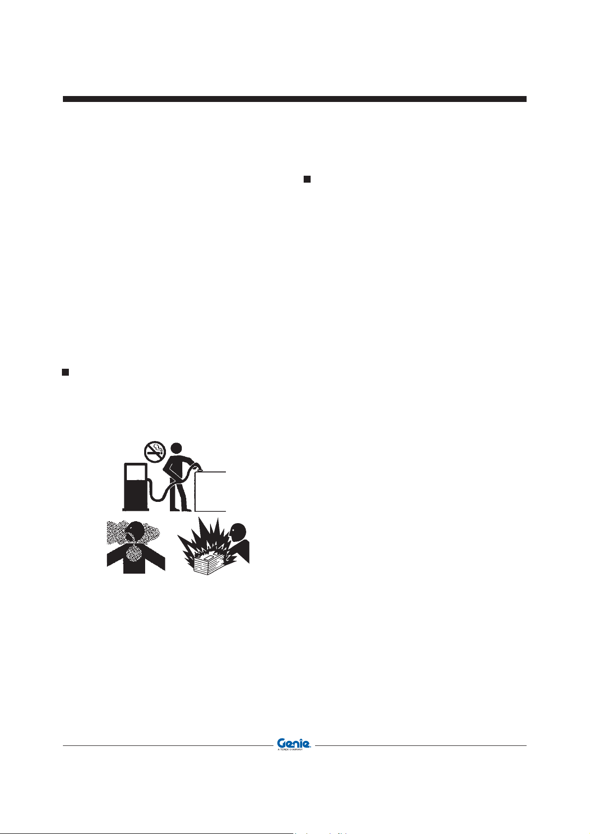
EXPLOSION OR FIRE hazards
• Do not start the engine if you smell or detect
LPG, gasoline, diesel fule or other explosive
substances.
• Do not refuel the machine with the engine
running.
• Refuel the machine and charge the battery only
in a well ventilated area away from sparks, naked
flames and lighted cigarettes.
Part No. 57.0009.0404 GTH-4518ER - GTH-4020ER - GTH-6025ER 21
Page 22
Operator’s Manual First Edition - Third Printing
Safety precautions
• Do not operate the machine in dangerous
environments or in places with flammable or
explosive gases or materials.
• Do not inject ether in engines equipped with glow
plugs.
• Do not leave fuel cans or bottles in unsuitable
places.
• Neither smoke nor use open flames in areas
subject to fire dangers and in presence of fuel,
oil or batteries.
• Carefully handle all flammable or dangerous
substances.
• Do not tamper with fire-extinguishers or pressure
accumulators.
DAMAGED COMPONENT hazards
• Do not use battery chargers or batteries with a
voltage above 12V to start the engine.
• Do not use the machine as a ground for
welding.
PERSONAL INJURY hazards
• Do not operate the machine in case of hydraulic oil
or air leak. Air or hydraulic oil leaks can penetrate
or burn the skin.
• Always operate the machine in a well ventilated
area to avoid carbon monoxide poisoning.
• Do not lower the boom if the area underneath is
not clear of personnel or obstructions.
22 GTH-4518ER - GTH-4020ER - GTH-6025ER Part No. 57.0009.0404
Page 23

'
&
Operator’s ManualFirst Edition - Third Printing
Description Of The Main Components
$
%
1 - Cylinder for telescopic boom
2 - Oil tank compartment
3 - Fuel tank compartment
4 - Driving cab according to ROPS-FOPS
provisions
5 - Rear left outrigger
6 - Rear axle
7 - Protection for forked loads and fork locking
during transfer
8 - Collapsible forks for palletised loads
9 - Attachment holding frame
#
"
!
10 - 4th boom section
11 - 3rd boom section
12 - 2nd boom section
13 - 1st boom section
14 - Left-hand side tool compartment
15 - Access step
16 - Front axle
17 - Front left stabilizer
18 - Front right stabilizer
19 - Engine compartment
Part No. 57.0009.0404 GTH-4518ER - GTH-4020ER - GTH-6025ER 23
Page 24

Operator’s Manual First Edition - Third Printing
Intentionally blank page
24 GTH-4518ER - GTH-4020ER - GTH-6025ER Part No. 57.0009.0404
Page 25

Operator’s ManualFirst Edition - Third Printing
Controls And Instruments
1 32 4
5 7 8109
6
11
12
13
14
C
VOLT
105
15
60
11
MODE
12
15
16
17
18
31
A BB BC D
1 2
132
3
4
4
19
21
20
22
K
INTINT
K
K
K
K
F6
F5
F4
F3
F2
F1
K
K
K
K
K
K
K
K
K
K
K
K
K
K
K
K
F27
F21
F15
F12
F26
F20
F14
F11
F25
F19
F13
F10
F24
F18
F9
INT
F23
F17
F8
F22
F16
F7
29
23
24
25
26
30
34
32
33
27
28
1 Fresh air flap
2 Forward/reverse gear selector
3 Control panel
4 Locking lever - steering column angle
adjustment
5 Switch: turn signals - lights - windscreen washer
- windscreen wiper
6 Light indicators and warning lights
7 Steering mode selector
8 Fuel gauge
9 Hydraulic oil temperature
10 Multipurpose display
11 Load limiter display
12 Battery voltage indicator graduated scale
13 Engine coolant temperature indicator
14 Road lights switch
15 Fog lamp switch
16 Cab air conditioning fan switch
17 Differential locking switch
18 Hazard warning light switch
19 Emergency pump pushbutton
20 Ignition switch
21 Cab-Road-Platform switch
22 Emergency stop switch
23 Load limiter disable selector
24 Inclinometer
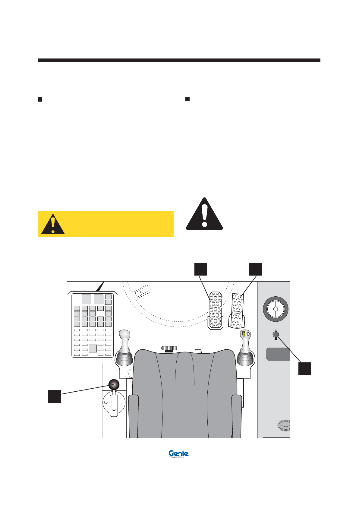
25 Throttle pedal
26 Service brake pedal
27 Multipurpose joystick (right)
28 Cab heater control cock
29 Fuse and relay box
30 Manual potentiometric accelerator
31 Warning light - Shift-on-fly system enabled
32 Multipurpose joystick (left)
33 Parking brake
34 Optional switches dashboard
Part No. 57.0009.0404 GTH-4518ER - GTH-4020ER - GTH-6025ER 25
Page 26

A BB BC D
1
2
3
4
1
3
2
4
Operator’s Manual First Edition - Third Printing
Controls And Instruments
Control Panel
51 Turntable rotation locking/unlocking button
52 Machine sway button: lifts the right side
53 Machine sway button: lifts the left side
54 Mechanical gearbox button
55 Button - Telescopic stabilizer retraction
56 Button - Telescopic stabilizer extension
57 Stabilizer lifting button
58 Stabilizer lowering button
59 Button 1: front left stabilizer selection/de-
selection
60 Button 2: front right stabilizer selection/de-
selection
52
53
54
61 Button 3: rear left stabilizer selection/de-
selection
62 Button 4: rear right stabilizer selection/de-
selection
63 Warning lights and luminous indicators
64 Function button A: automatic machine
levelling
65 Function button B: not active
66 Function button C: not active
67 Function button D: stabilizer lifting/lowering
flush with wall
55
56
51
26 GTH-4518ER - GTH-4020ER - GTH-6025ER Part No. 57.0009.0404
64 65 66 67
57
58
59
60
61
62
63
Page 27

Operator’s ManualFirst Edition - Third Printing
Controls And Instruments
20 _ Ignition Switch
Three-position switch:
No circuit under voltage, key can be removed
and engine is stopped.
Circuits under voltage for engine start-up.
Board controls and instruments are on.
Wait until the warning light 6.2 signalling
the glow plugs preheating goes off before
proceeding with the engine starting.
Engine start-up; when released, key springs
back to pos. I automatically.
2 _ Forward/Reverse Gear Selector Switch
The lever lets you select the forward or reverse
speed. The lever must be pulled upwards before
engaging the selected speed.
Three-position switch with lock in neutral position:
0 Neutral position; no gear engaged
1 Shift lever to pos. 1 to select the forward
gear
2 Shift lever to pos. 2 to select the reverse
gear
1
0
2
Part No. 57.0009.0404 GTH-4518ER - GTH-4020ER - GTH-6025ER 27
Page 28

Ι
Ι
I
Ι
Ι
I
Ι
Ι
I
Ι
Ι
I
Ι
Ι
I
Ι
Ι
I
Operator’s Manual First Edition - Third Printing
Controls And Instruments
5 _ Turn Signals - Windscreen Wiper - Horn -
Lights
Horn function:
When sliding the lever along its axis, horn switches
on, independently from other pre-set functions.
Windscreen washer function:
Push the second stage of the lever along its axis to
direct a jet of water onto the cab windscreen.
Windscreen wiper function:
To operate the windscreen wiper, rotate the lever tip
to one of the four positions:
I Intermittence (not activated)
0 Wiper OFF
J Low speed
I I High speed
Lights function:
To switch the handler lights, lever can be set to three
different positions along its horizontal axis:
0 low beam ON, stable condition
1 high beam ON, stable condition
2 high beam used for intermittent signalling;
when released, the lever springs back to
position 0.
Turn signals function:
Set lever to pos. 1 to indicate a turn leftwards or to
pos. 2 to indicate a turn rightwards.
28 GTH-4518ER - GTH-4020ER - GTH-6025ER Part No. 57.0009.0404
Page 29
Operator’s ManualFirst Edition - Third Printing
Controls And Instruments
Brakes
26 _ Service Brake Pedal
By gradually pressing the pedal, translation is slowed
down and, by stepping the pedal down to end of
stroke, the machine is stopped.
33 _ Parking Brake
To engage the parking brake, pull the lever upward
while holding the locking button pressed down.
Release the button when reaching the required
braking tension. It operates on the axle shafts of the
rear axle and, when engaged, it cuts both forward
and reverse gear off.
CAUTION
Never use the parking brake to slow down the
machine, unless in an emergency. It may reduce
the brake efficiency.
Accelerator control
25 _ Throttle Pedal
Its pressure controls the engine rpm and the machine
speed. It is fitted with an adjustable stop in the lower
part.
30 _ Manual Potentiometric Accelerator
Turning the regulator 30 clockwise lets you increase
the engine speed.
Turning the regulator counter-clockwise lets you
decrease the engine speed.
The manual gas control can only be used with
man-platform, winch, mixing bucket, hook and
maintenance jib.
26 25
K
INTINT
K
K
K
K
K
K
K
K
F12
F6
F11
F5
F10
F4
F9
F3
F8
F2
F7
F1
K
K
K
K
K
K
K
K
K
K
K
K
F27
F21
F15
F26
F20
F14
F25
F19
F13
F24
F18
INT
F23
F17
F22
F16
30
33
Part No. 57.0009.0404 GTH-4518ER - GTH-4020ER - GTH-6025ER 29
Page 30
MO
1
Operator’s Manual First Edition - Third Printing
Controls And Instruments
Safety and Emergency Devices
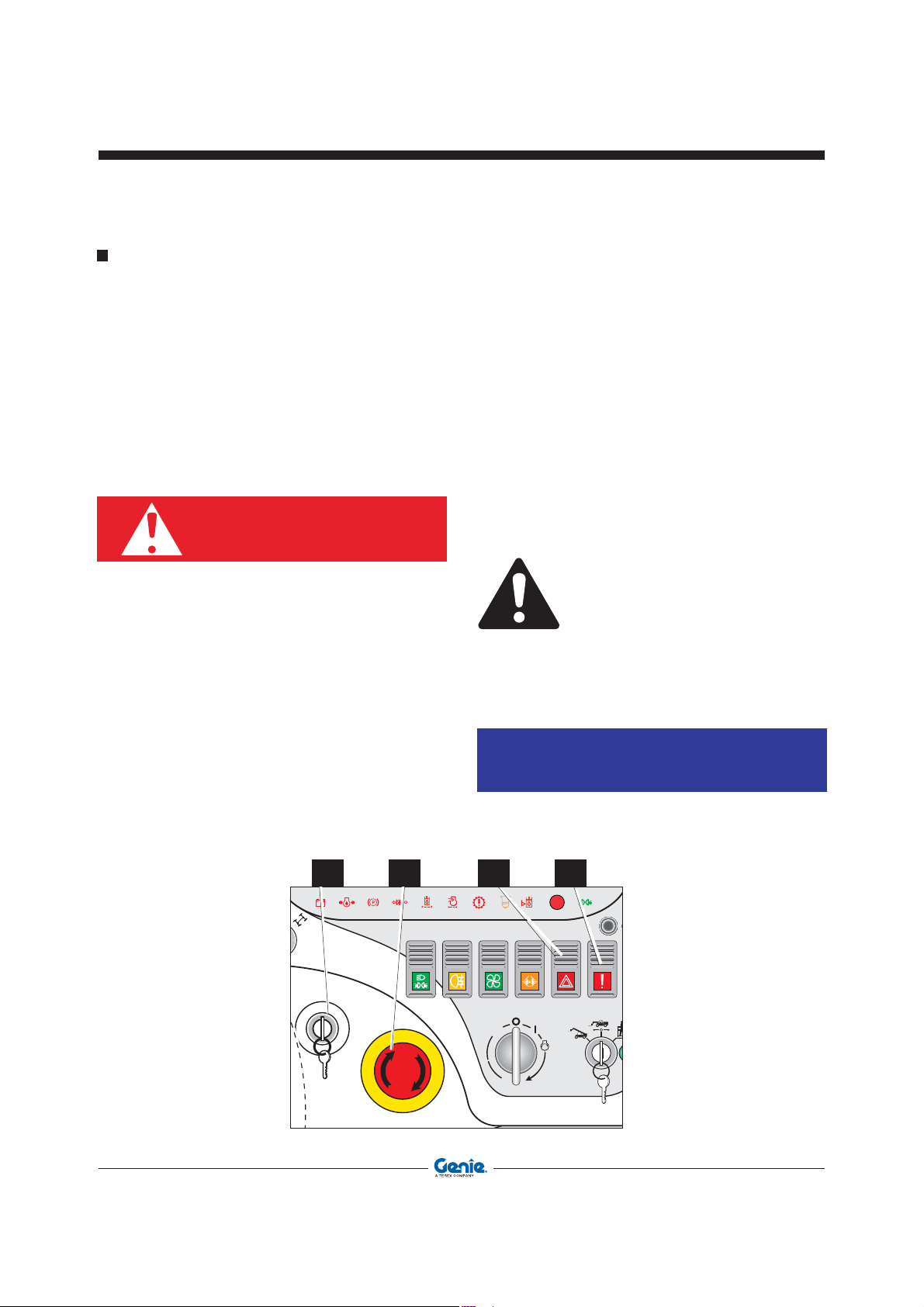
22 _ Emergency Stop Pushbutton
By pressing this button, the engine of the machine
is shut down.
Before restarting the machine, it is necessary to reset
the pushbutton by rotating it clockwise.
23 _ Load Limiter Disable Selector
The load limiter can be deactivated operating the
key-selector placed under the protection cover.
DANGER
WORKING WITH THE LOAD LIMITING SYSTEM CUT OUT CAN
RESULT IN A MACHINE OVERTURNING AND IN SERIOUS
INJURY.
18 _ Hazard Warning Lights Switch
Fitted with on-off position, it switches on the turn
signals simultaneously. When the hazard warning
light is lit, the relevant switch and the turn signals
light start flashing.
19 _ Emergency Pump Control
It is located on the left side of the dashboard and has
two positions with automatic return to centre.
When the button is held pressed down, the emergency
pump is activated. Releasing the button stops the
pump.
The activation of the emergency pump should be done
with the simultaneous operation of the cab controls
or the main valve manual controls.
Correct operation sequence:
• Turn the ignition key 20 to position I.
• Shift the control lever to the desired position.
• Press the emergency pump control button 19.
Do not start the emergency pump before shifting
the control lever. The emergency pump is driven
by an electric motor. Therefore, it is advisable to
let the motor run for about 30 seconds, then stop
for about 2 minutes to let the motor cool down.
NOTICE
Check the operation of the emergency pump every
week as it could get damaged if it is not used.
19182223
30 GTH-4518ER - GTH-4020ER - GTH-6025ER Part No. 57.0009.0404
Page 31
Speed Controls
A BB BC D
1
2
3
4
1
3
2
4
Operator’s ManualFirst Edition - Third Printing
Controls And Instruments
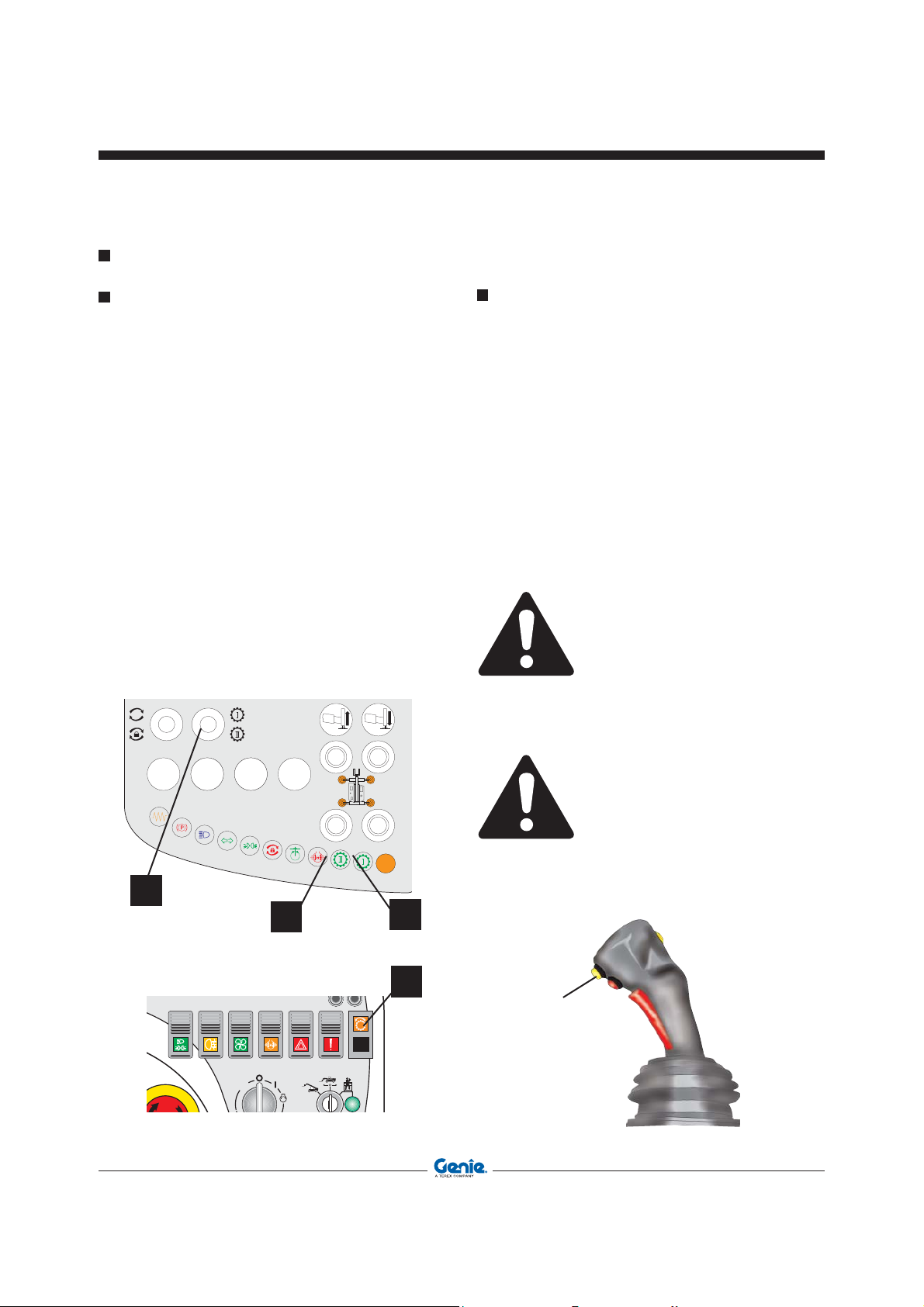
MECHANICAL Gear Change Control
Pushbutton 54 lets you select the mechanical speed
you wish.
• Pressing the button lets you shift from the first
speed to the second speed.
• Indicator lights 78 and 79 show the selected
speed:
- indicator 79 comes on with a green flashing
light to indicate that the first speed has been
selected
- indicator 78 comes on with a green flashing
light to indicate that the second speed has
been selected
Shift-On-Fly Pushbutton
The Shift-on-fly system lets you shift from one gear
to another when the machine is travelling.
The yellow activation pushbutton 1 is located at the
back of the joystick handle and shall be pressed down
only when the warning light 31 is lit.
This warning light flashes to warn of any errors or
problems. In such case, gear won’t be shifted.
When the warning light 31 is lit with a solid light,
pressing the button lets you shift from one gear to
another (from 1st speed to 2nd speed and from 2nd
speed to 1st speed).
Indicator lights 78 and 79 show the selected
speed.
The Shift-on-fly system can only be used within
the admissible speed range. Always check that
warning light 31 is lit before using the system.
54
Part No. 57.0009.0404 GTH-4518ER - GTH-4020ER - GTH-6025ER 31
A micro-switch built in the driver’s seat, inhibits
the speed engagement if you aren’t seated
correctly.
78
79
31
Page 32

Operator’s Manual First Edition - Third Printing
Controls And Instruments
Steering Mode Selection
7 _ Steering Mode Selector
The three-position switch for the selection of the
steering mode is located on the dashboard to the
right,:
1 Crab steering
0 Two-wheel steering
2 Four-wheel steering
7
Road/Jobsite/Platform Selection
21 _ Road/Jobsite/Platform Selector
Three-position switch located on the dashboard, to
the right:
• Rotating the switch to position 1 activates the cab
controls
• Rotating the switch to position 0 configures the
machine for road circulation
• When the switch is rotated to position 2, the
ignition key can be removed and the platform
controls are activated. The green indicator light
A comes on.
NOTICE
Before switching the controls from the cab to the
platform, rotate the ignition switch to position
I.
MODE
12
32 GTH-4518ER - GTH-4020ER - GTH-6025ER Part No. 57.0009.0404
21
Page 33

Auxiliary Drive Controls
1
14 _ Road Lights Switch
Three-position switch placed on the right side of the
dashboard:
0 Lights OFF
1 Position lights ON (the switch indicator lights up
partially).
2 Low beam ON (the switch indicator fully lights
up).
15 _ Fog Lamp Switch
Two-position switch placed on the right side of the
dashboard:
0 Fog lamp OFF
1 Fog lamp ON (the switch indicator lights up).
16 _ Air Conditioning Fan Switch
Three-position switch:
0 OFF
1 Low speed
2 High speed
Operator’s ManualFirst Edition - Third Printing
Controls And Instruments
17 _ Differential Lock Switch
The button is located on the right side of the
dashboard and has two stable positions:
0 Axle differential unlocked
1 Axle differential locked.
The locked condition is signalled by indicator light
77.
The differential lock device must only be used in
the event of a stall situation (very uneven ground,
mud, wheels not evenly resting on the ground). In
all other events, the Limited-Slip device (fitted to
the front axle) lets you face all normal operation
condition.
28 _ Cab Heater Control Cock
Located on the left side of the driving seat base.
• Turn the cock clockwise to switch off heated
air.
• Turn the cock counter-clockwise to switch on the
cab heater.
• Adjust the flow of heated air in the cab operating
the A/C fan switch 16.
171614 15
28
Part No. 57.0009.0404 GTH-4518ER - GTH-4020ER - GTH-6025ER 33
Page 34

Operator’s Manual First Edition - Third Printing
Controls And Instruments
34 _ Optional switches dashboard
Air Condition Switch (OPTIONAL)
Two-position switch:
0 OFF
1 ON
Work Lights Switch (OPTIONAL)
Two-position switch
0 Lights OFF
1 Lights ON
Auxiliary Hidraulic Circuit (OPTIONAL)
Two-position switch. The pressure of this button
causes the switching of the hydraulic circuit for
the movement of the attachments equipped with
auxiliary lines.
B
0 Oil to the main circuit
1 Attachments hydraulic circuit
Switching
The selector has a block to keep the switch pressed.
Before switching the selector to another position,
unlock control B at the top of the selector.
Mixing Bucket Switch (OPTIONAL)
Two-position switch. The pressure of this button
enables the movement of the internal mixer of the
bucket.
B
0 Mixer OFF
1 Mixer ON
The selector has a block to keep the switch pressed.
Before switching the selector to another position,
unlock control B at the top of the selector.
34 GTH-4518ER - GTH-4020ER - GTH-6025ER Part No. 57.0009.0404
Page 35

Instruments
Operator’s ManualFirst Edition - Third Printing
Controls And Instruments
8 _ Fuel Gauge
This indicates the fuel level in the tank. When the
indicator reaches the red zone, there are roughly
5 litres in the tank and the warning light 6.1 comes
on.
13 _ Engine Coolant Temperature Indicator
It indicates the engine coolant temperature.
If the red warning light 6.15 comes on (temperature
above 100 °C), stop the engine and find and rectify
the problem (radiator dirty, low engine coolant level,
etc.).
10
8
10 _ Multipurpose Display
When the machine is started, the graphic display
shows:
• Engine rpm
• Hour-meter / speed
• Hydraulic oil temperature
• Battery voltage
• Service (next service intervals)
Additionally, the function buttons MODE 1 and MODE
2 let you access to and scroll through the menus and
sub-menus with the following functions:
• Language selection (Italian/English)
• Service (password-protected function reserved
to authorised repair shops)
• Display of the diesel engine errors
13
C
105
60
VOLT
15
11
6.15
6.1
MODE
12
Part No. 57.0009.0404 GTH-4518ER - GTH-4020ER - GTH-6025ER 35
Page 36

°C
105
60
VOLT
15
11
SERVICE
50 h
ENGINE RPM
0
0,4
Operator’s Manual First Edition - Third Printing
Controls And Instruments
Multipurpose Display
When the machine is started, the display shown in
fig. A will appear:
• The black bars 41 on the left indicate the hydraulic
oil temperature.
FIG. A
°C
105
60
SERVICE
50 h
0
ENGINE RPM
VOLT
15
11
0,4
During normal operation, the temperature should
be comprised between 60 and 105 degrees
corresponding to the green section of the scale
shown on the left of the display.
If a higher temperature is reached (and the bars
of the red zone of the scale come on), you should
stop the machine and find and rectify the problem
before restarting the machine.
• The black bars 43 on the right show the battery
charge when the engine is stopped, and the
alternator charge voltage when the engine is
running.
If the voltage displayed is less than 11 Volt, the
alternator charge could be insufficient or the
battery could be discharged. If the voltage is
above 15 Volt, the alternator voltage is above
the normal working voltage. In both cases, you
should stop the machine and find and rectify the
problem.
• In the central part 42 of the display, starting from
the top, you find:
This indicates when next maintenance operations
should be done.
Pressing the MODE 1 button, the speed is
displayed.
This indicates the diesel engine rpm.
During normal operation, the temperature
should be comprised between 11 and 15 volt
corresponding to the green section of the scale
on the right of the display.
36 GTH-4518ER - GTH-4020ER - GTH-6025ER Part No. 57.0009.0404
This is the hour-meter indicating the running time
of the machine.Use this meter to correctly gauge
the service intervals.
Page 37

Use of menus and sub-menus
°C
105
60
VOLT
15
11
SELEZIONA LINGUA
SERVICE
VISUALIZZA ERRORI
ESCI
°C
105
60
VOLT
15
11
°C
105
60
VOLT
15
11
SELEZIONA LINGUA
SERVICE
VISUALIZZA ERRORI
ESCI
ITALIANO
INGLESE
ESCI
°C
105
60
VOLT
15
11
SELEZIONA LINGUA
SERVICE
VISUALIZZA ERRORI
ESCI
°C
105
60
VOLT
15
11
SELEZIONA LINGUA
SERVICE
VISUALIZZA ERRORI
ESCI
°C
105
60
VOLT
15
11
SERVICE
ENGINE RPM
0
0,4
50 h
Operator’s ManualFirst Edition - Third Printing
Controls And Instruments
Use the two buttons MODE 1 and MODE 2 to gain
access and scroll through menus and sub-menus.
Press the two buttons MODE 1 and MODE 2
simultaneously to access to the menu.
Press button MODE 1 to confirm any selection
made.
Press button MODE 2 to scroll through the menu
lists (when the last item of the list is reached, the
first item is displayed).
Quitting the menu
• Select EXIT using button MODE 2.
• Press button MODE 1 to quit and display the
Part No. 57.0009.0404 GTH-4518ER - GTH-4020ER - GTH-6025ER 37
home page.
Page 38

°C
105
60
VOLT
15
11
SELEZIONA LINGUA
SERVICE
VISUALIZZA ERRORI
ESCI
°C
105
60
VOLT
15
11
ITALIANO
INGLESE
ESCI
°C
105
60
VOLT
15
11
SELEZIONA LINGUA
VISUALIZZA ERRORI
ESCI
SERVICESERVICE
°C
105
60
VOLT
15
11
AZZERA SERVICE
ESCI
Operator’s Manual First Edition - Third Printing
Controls And Instruments
Language selection sub-menu
• Select SELECT LANGUAGE using button MODE
2.
• Press button MODE 1 to open the sub-menu.
• Press button MODE 2 to scroll through the list.
Password protected service sub-menu
(reserved to authorised service centres)
• Access to this sub-menu is reserved to authorised
service centres and is therefore password
protected.
• If you have entered the SERVICE menu
accidentally, press buttonMODE 2, select EXIT
and then press button MODE 1 to confirm.
• Press button MODE 2 to select the language and
quit the sub-menu (the EXIT command lets you
quit the menu without changing any settings).
• By quitting the sub-menu, you will go back to the
SERVICE window of the main menu.
38 GTH-4518ER - GTH-4020ER - GTH-6025ER Part No. 57.0009.0404
• By quitting the sub-menu, you will go back to the
DISPLAY ERRORS window of the main menu.
Page 39

Error display sub-menu
°C
105
60
VOLT
15
11
SELEZIONA LINGUA
SERVICE
VISUALIZZA ERRORI
ESCI
°C
105
60
VOLT
15
11
...
ESCI
°C
105
60
VOLT
15
11
...
ESCI
• Select DISPLAY ERRORS using button MODE
2.
Operator’s ManualFirst Edition - Third Printing
Controls And Instruments
• By quitting the sub-menu, you will go back to the
EXIT window of the main menu.
• Press button MODE 1 to open the sub-menu.
• Press button MODE 2 to scroll through the errors
list.
• To quit the sub-menu, select EXIT (using button
MODE 2) and then press button MODE 1 to
confirm.
Part No. 57.0009.0404 GTH-4518ER - GTH-4020ER - GTH-6025ER 39
Page 40

Operator’s Manual First Edition - Third Printing
Controls And Instruments
Right Panel Luminous Indicators (ref.6)
6.1 Warning light - fuel reserve
This red light comes on to alert to a low fuel
level in the tank.
6.2 Warning light - glow plugs preheating
This amber light indicates the pre-heating of the
engine glow plugs. Before starting the engine
wait for this light to go off.
If the light fails to go off, a glow plug could be
broken.
The machine can be started normally without
pre-heating up to a temperature of -12°C.
6.3 Warning light - low battery charge
This red light comes on to alert to a low charge
by the alternator.
6.4 Warning light - low engine oil pressure
This red light comes on to warn that the
pressure in the engine lubrication system is
not enough for a proper operation.
Stop the engine and find and rectify the
problem.
6.5 Warning light - parking brake engaged
This red light comes on to warn that the lever of
the parking brake is not in the neutral position
(parking brake engaged).
6.6 Warning light - low brake pressure
This red light comes on to warn that the braking
circuit pressure is not enough for a proper
operation.
6.7 Warning light - hydraulic oil filter clogged
When this lamp sets to on, immediately change
the oil filter on the return line to the tank.
6.8 Warning light - air filter restricted
When this red light comes on, clean or change
the air filter cartridges (see “Maintenance”
section).
6.9 Warning light - not active
6.10 Warning light - water in fuel
This yellow light comes on to alert to the
presence of water in fuel.
6.11 Warning light - low hydraulic oil level
This light comes on to alert to a low level
of the hydraulic oil for a correct functioning.
Replenish and eliminate the oil leak.
6.12 General Warning light
This red light comes on to warn of a problem
of the machine. Contact TEREXLIFT Service
Center.
6.13 Warning light - position lights
Green warning light that signals when the
position lights are ON.
6.14 Warning light - “Read the manual”
This amber light indicates a failure of the
machine. For the error codes, please refer
to the engine operation and maintenance
manual.
6.15 Warning light - high coolant temperature
This red light comes on to alert to a too high
temperature of the cooling medium.
Stop the engine and find and rectify the
problem.
6.1
6.3
6.2
6.4 6.5 6.6 6.7 6.8
6.9
6.10
6.11
6.14 6.15
MODE
12
6.12
6.13
40 GTH-4518ER - GTH-4020ER - GTH-6025ER Part No. 57.0009.0404
Page 41

Left Panel Luminous Indicators
Operator’s ManualFirst Edition - Third Printing
Controls And Instruments
70 Warning light - not active
71 Warning light - parking brake engaged
This red light comes on to warn that the lever of
the parking brake is not in the neutral position
(parking brake engaged).
72 Warning light - high beam
Blue warning light that signals when the high
beam is ON.
73 Warning light - turn signals
Green flashing indicator light that signals when
the turn signals are ON.
74 Warning light - position lights
Green warning light that signals when the
position lights are ON.
75 Warning light - turntable rotation blocked
This red light comes on to warn that the
turntable rotation is blocked. Remove the
locking pin before turning the turntable.
76 Warning light - turntable aligned
This green light comes on to warn that the
turntable is in line with the longitudinal axis.
In this condition, the locking pin can be driven
in.
77 Warning light - differential lock
This red light comes on to warn that the
differential lock has been activated.
78 Warning light - second speed engaged
This green flashing light comes on to warn that
the second speed has been engaged.
79 Warning light - first speed engaged
This green flashing light comes on to warn that
the first speed has been engaged.
80 Warning light - machine levelled
This amber light comes to indicate that:
- the machine is levelled (fixed light)
- levelling is in progress (flashing light)
81 Warning lights - stabilizer movements
These amber lights come on to indicate the
selected stabilizer:
1 front left stabilizer
2 front right stabilizer
3 rear left stabilizer
4 rear right stabilizer
81
70 71 72 73 74 7675
Part No. 57.0009.0404 GTH-4518ER - GTH-4020ER - GTH-6025ER 41
81
81
81
80
77 78 79
Page 42

CAUTION
DANGER
Operator’s Manual First Edition - Third Printing
Controls And Instruments
CONTROL LEVERS
The handlers are equipped with two multipurpose
joysticks 27 and 32 that let you operate all the
machine movements.
The right joystick 27 is installed to one side of the
driver’s seat; the left joystick 32 is installed on a
rotating arm which can moved up to enter or leave
the control place.
At the front of both joysticks, there is the intentional
control button 4 which must be held pressed down
until the manoeuvre has been completed. If this button
is not pressed, shifting the joystick to any direction
won’t activate any function.
The joysticks can be shifted to any of the four
directions, that is forward, backward, to the right or
to the left.
The right joystick has two additional buttons 2 and 3
at the top for the activation of further functions.
Pushbutton 1 lets you use the mechanical "Shift-on
fly" system.
32
27
Seize the control lever correctly and move it
gently.
The motion speed of the actuators depends on
the lever position: a small motion results in a
slow motion of the actuators; vice versa, a full
range motion of the lever corresponds to the
max. speed of the actuator.
The control lever shall be operated only when
correctly seated in the driving place.
Before operating the control lever, make sure
that nobody is within the working range of the
machine.
42 GTH-4518ER - GTH-4020ER - GTH-6025ER Part No. 57.0009.0404
Page 43

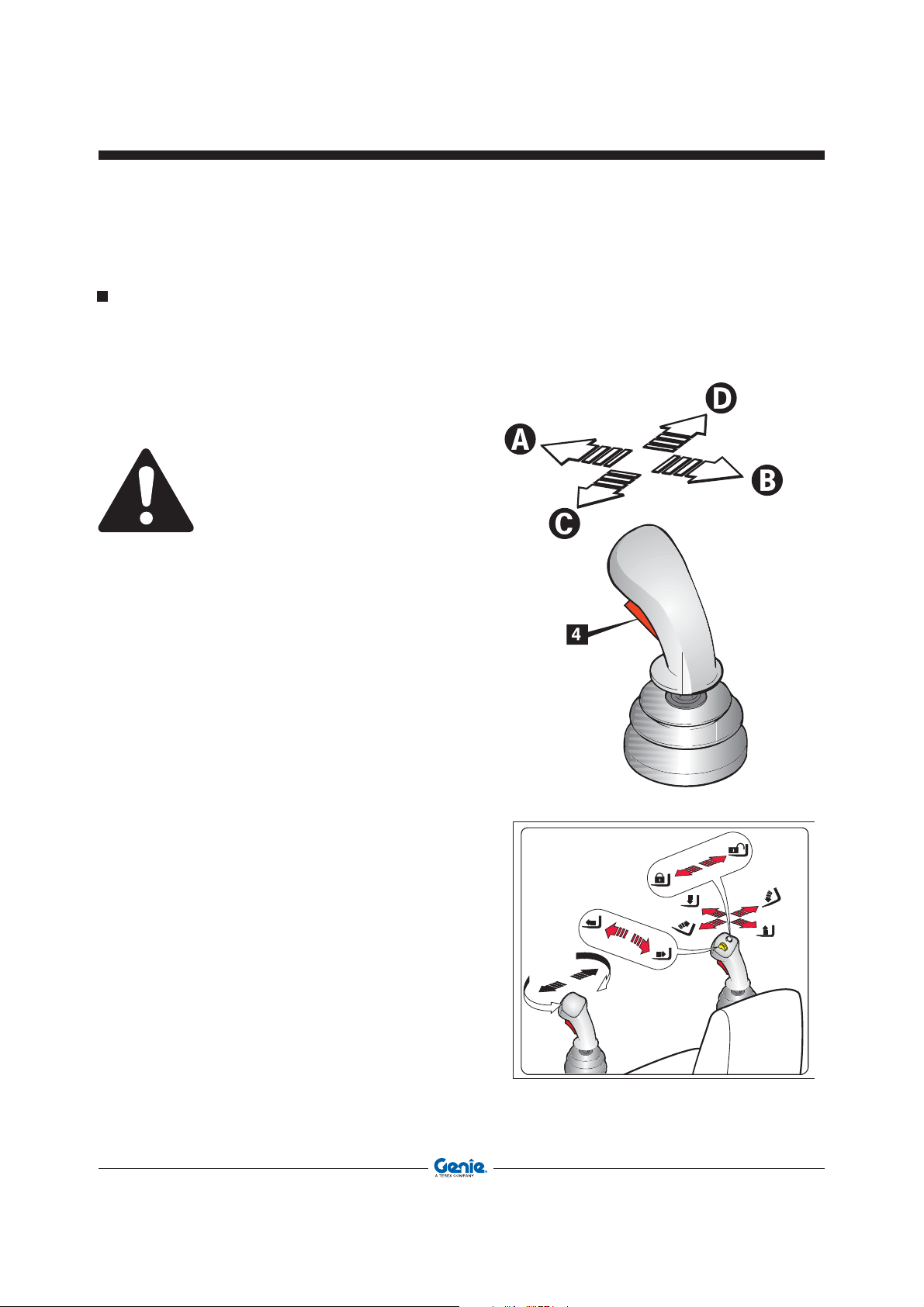
Function Selection
Right Joystick:
Once the intentional control pushbutton 4 has been
pressed, you can use the joystick to activate the
following functions:
• Boom lowering/lifting
To activate the function, shift the joystick to A
- B.
• Telescope retraction/extension
To activate the function, press button 2 to A - B
without shifting the joystick.
• Attachment frame forward/back pitching
To activate the function, shift the joystick to C
- D.
• Attachment coupling/release
To activate the function, hold button 3 pressed
down and move the joystick to C or D
Operator’s ManualFirst Edition - Third Printing
Controls And Instruments
The following controls do not need you to press the
intentional control button 4 for their operation:
• Shift-on-fly
To change mechanical gear, press the yellow
button 1 when the relevant warning light on the
dashboard is lit with a solid light.
If, during operation, button 4 is released for more
than 0.5 seconds, the movement stops.
To restart the movement, re-select the
function.
Part No. 57.0009.0404 GTH-4518ER - GTH-4020ER - GTH-6025ER 43
Page 44
Operator’s Manual First Edition - Third Printing
Controls And Instruments
Left Joystick:
Once the intentional control pushbutton 4 has been
pressed, you can use the joystick to activate the
following functions:
• Turntable rotation
to activate the function, shift the joystick to C or
D.
If, during operation, button 4 is released for more
than 0.5 seconds, the movement stops.
To restart the movement, re-select the
function.
44 GTH-4518ER - GTH-4020ER - GTH-6025ER Part No. 57.0009.0404
Page 45
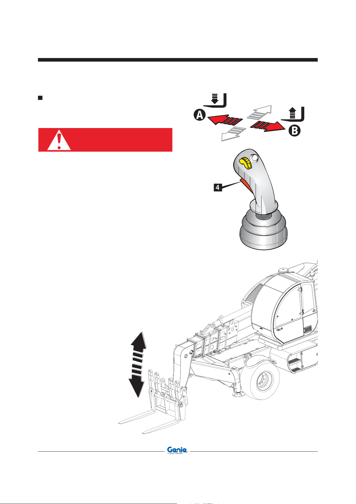
Lifting/Lowering The Boom
DANGER
RIGHT JOYSTICK
Before operating the boom, make sure that nobody
is within the working range of the machine.
To lift or lower the boom:
• Set thecontrol lever to central position and press
button 4.
• Smoothly shift the lever to position B to lift the
boom; shift the lever to position A to lower the
boom.
Operator’s ManualFirst Edition - Third Printing
Controls And Instruments
Part No. 57.0009.0404 GTH-4518ER - GTH-4020ER - GTH-6025ER 45
Page 46
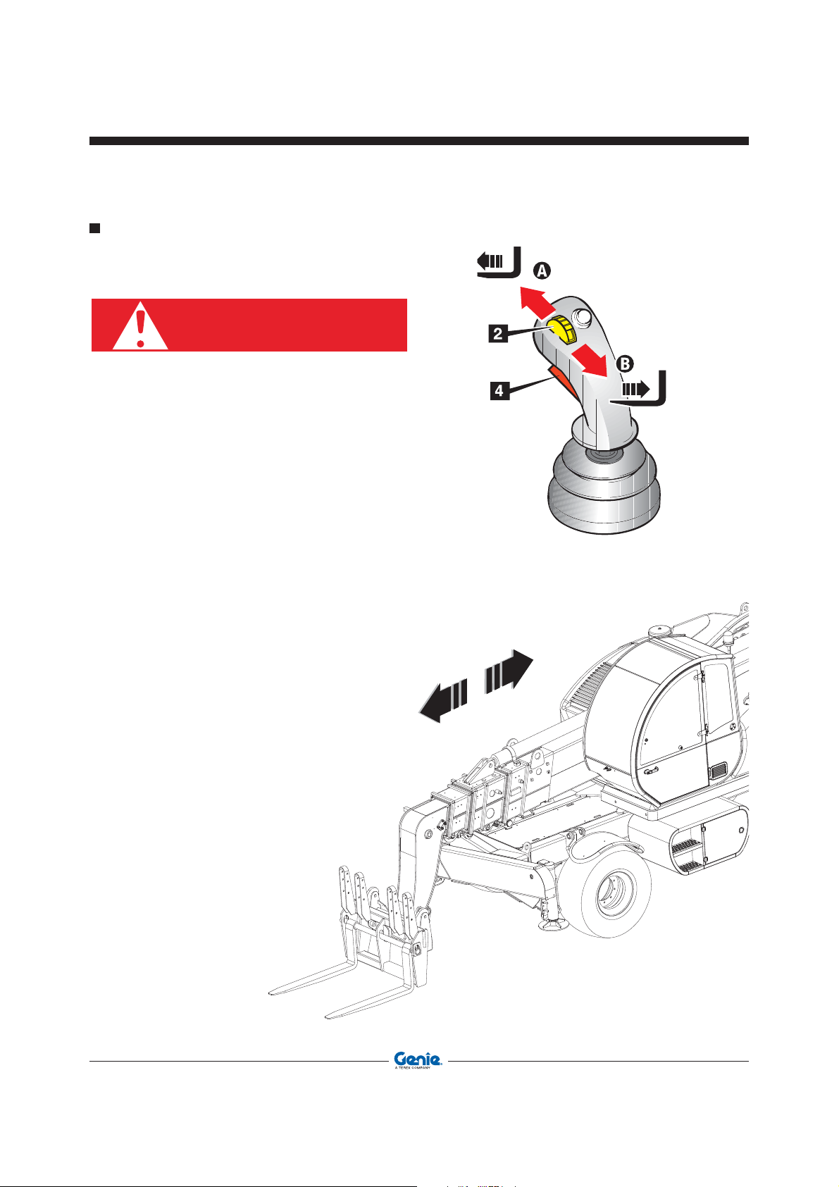
DANGER
Operator’s Manual First Edition - Third Printing
Controls And Instruments
Extending/Retracting The Boom
RIGHT JOYSTICK
Before operating the boom, make sure that nobody
is within the working range of the machine.
To extend or retract the boom telescopes:
• Set the control lever to central position and press
button 4.
• Press button 2 to A to move out the boom
telescope; press the same button to B to move
in the boom telescope.
46 GTH-4518ER - GTH-4020ER - GTH-6025ER Part No. 57.0009.0404
Page 47
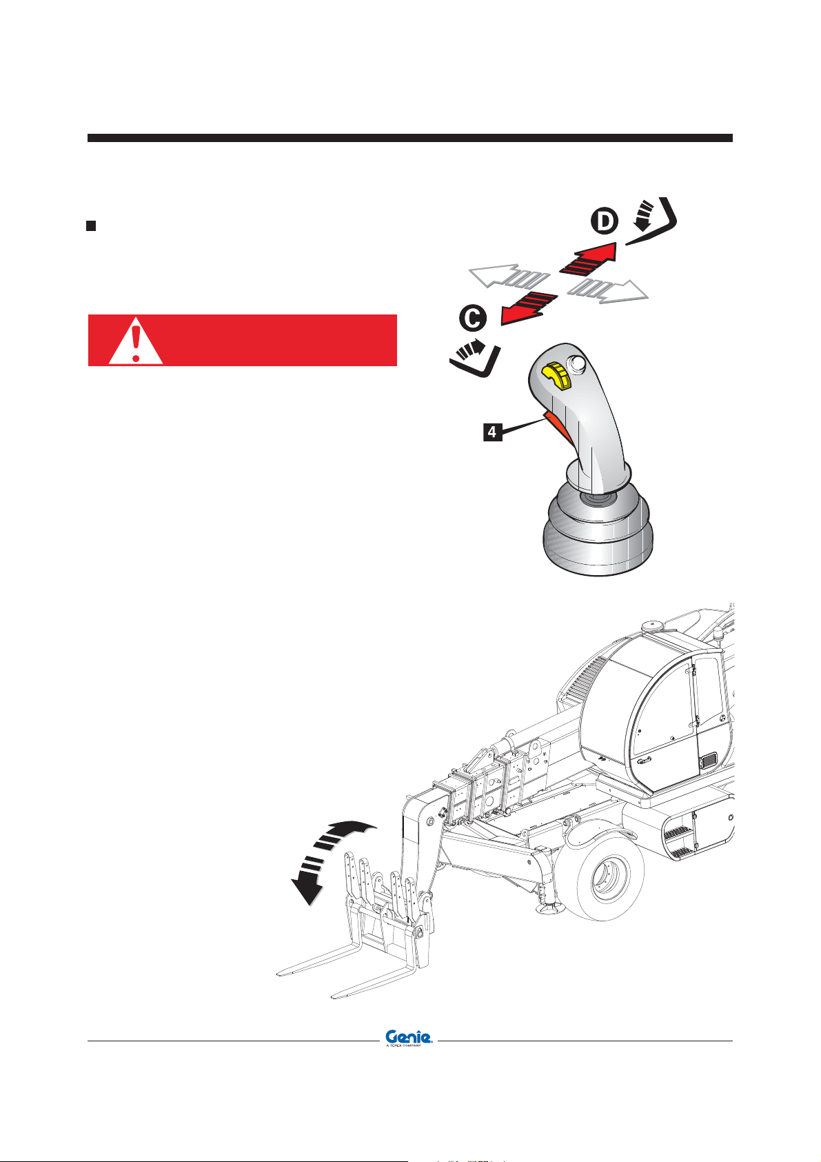
Pitching The Attachment Holding Frame
DANGER
Forward/Back
RIGHT JOYSTICK
Before operating the boom, make sure that nobody
is within the working range of the machine.
To pitch forward/back the attachment holding
frame:
• Set the control lever to central position and press
button 4.
• Smoothly shift the lever to position D to pitch the
holding plate forward; shift the lever to position
C to pitch the plate back.
Operator’s ManualFirst Edition - Third Printing
Controls And Instruments
Part No. 57.0009.0404 GTH-4518ER - GTH-4020ER - GTH-6025ER 47
Page 48
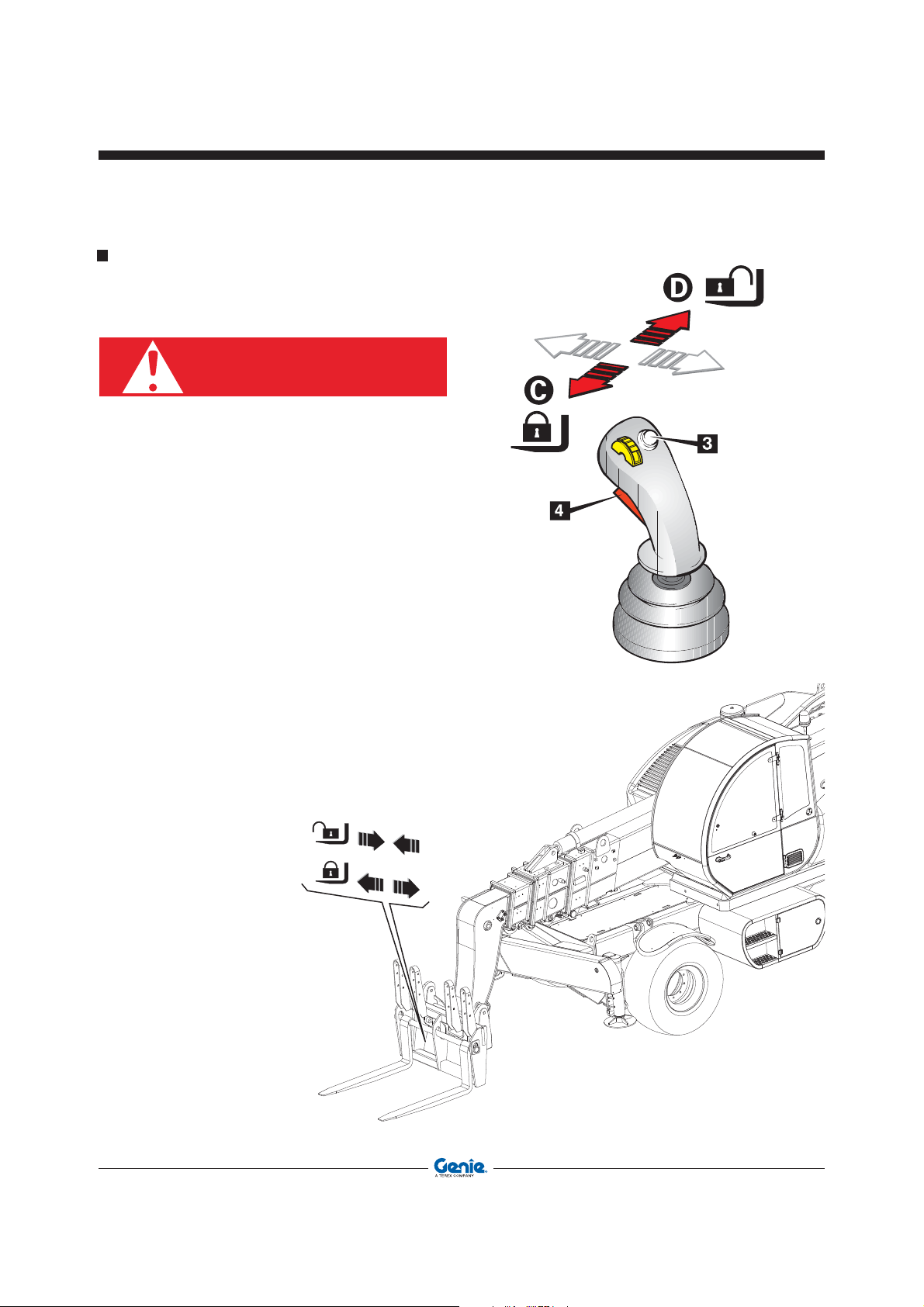
DANGER
Operator’s Manual First Edition - Third Printing
Controls And Instruments
Quick-Coupling The Attachments
RIGHT JOYSTICK
Before operating the boom, make sure that nobody
is within the working range of the machine.
To lock the attachments:
• Set the control lever to central position and press
button 4.
• Press button 3 to select the attachment locking
function and hold it pressed until the end of the
motion.
• Smoothly shift the lever to position C to lock the
attachment; shift the lever to position D to unlock
the attachment.
48 GTH-4518ER - GTH-4020ER - GTH-6025ER Part No. 57.0009.0404
Page 49

Turntable Rotation Control
NOTICE
LEFT JOYSTICK
Before operating the turntable rotation control,
check that the locking pin has been removed.
To rotate the turntable:
• Shift the control lever to central position and press
button 4.
• Smoothly shift the lever to direction D to rotate
the turntable clockwise; shift the lever to direction
C to rotate the turntable counter-clockwise.
Operator’s ManualFirst Edition - Third Printing
Controls And Instruments
Part No. 57.0009.0404 GTH-4518ER - GTH-4020ER - GTH-6025ER 49
Page 50
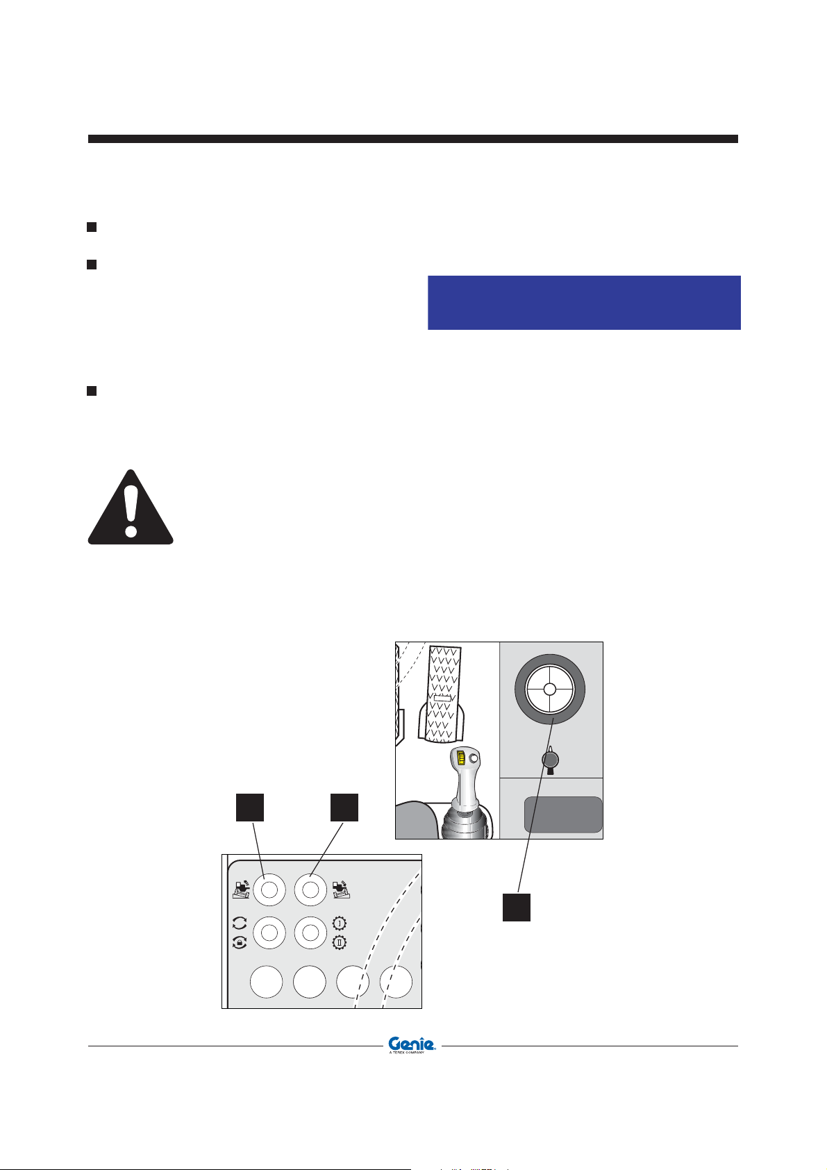
A BB BC D
NOTICE
Operator’s Manual First Edition - Third Printing
Controls And Instruments
MACHINE SWAY CONTROL
Automatic levelling
To level the machine:
• Press button 52 to raise the right side of the
machine.
• Press button 53 to raise the left side of the
machine.
Automatic levelling of the stabilized machine
• lower all the stabilizers to the ground and press
button A. During operation, the machine will level
automatically.
Operate the sway control only when the turntable
is locked in central position and the boom is at
max 10° .
Check that the machine is level on the inclinometer
24. The air bubble must be right in the middle of
the instrument.
52 53
24
50 GTH-4518ER - GTH-4020ER - GTH-6025ER Part No. 57.0009.0404
Page 51

STABILIZER CONTROL
On the left control panel, there are a series of controls
for operating the stabilizers.
Pressing or releasing buttons 1 - 2 - 3 - 4 lets you
select or de-select the corresponding stabilizer:
1 Front left stabilizer
2 Front right stabilizer
3 Rear left stabilizer
4 Rear right stabilizer
Stabilizers can be moved one at a time or all at the
same time by repeating for each of them the same
operating sequence.
Indicator lights 5 - 6 - 7 - 8 show the selected
stabilizer.
5 Front left stabilizer
6 Front right stabilizer
7 Rear left stabilizer
8 Rear right stabilizer
Operator’s ManualFirst Edition - Third Printing
Controls And Instruments
9
11
1
5
7
3
10
12
2
6
8
4
Pressing or releasing buttons 9 - 10 - 11 - 12 lets
you move the selected stabilizer:
9 Stabilizer in
10 Stabilizer out
11 Stabilizer pad up
12 Stabilizer pad down
Part No. 57.0009.0404 GTH-4518ER - GTH-4020ER - GTH-6025ER 51
Page 52

NOTICE
WARNING
NOTICE
Operator’s Manual First Edition - Third Printing
Controls And Instruments
Using the stabilizers:
• Select the stabilizer you wish to use by pressing
the relevant selection button 1 - 2 - 3 - 4, and
check that the indicator light of the selected
stabilizer comes on.
• Hold button 10 pressed down to extend the
stabilizer.
• Hold button 12 pressed down to lower stabilizer
pad to the ground.
• De-select the stabilizer by pressing the relevant
button 1 - 2 - 3 - 4, and check that the indicator
light of the de-selected stabilizer goes off.
Before lowering the stabilizer pads to the
ground, make sure no one is within their working
range.
Bringing the stabilizers to the rest position:
• Select the stabilizer you wish by pressing the
relevant selection button 1 - 2 - 3 - 4, and check
that the indicator light of the selected stabilizer
comes on.
• Hold button 11 pressed down to raise the
stabilizer pad.
• Hold button 9 pressed down to retract the
stabilizer.
• De-select the stabilizer by pressing the relevant
button 1 - 2 - 3 - 4, and check that the indicator
light of the de-selected stabilizer goes off.
Correct sequence to lower the stabilizers:
• Extend the stabilizer to end of stroke
• Lower the stabilizer pad and make sure it rests
on a firm ground.
To raise the stabilizers:
• Raise the stabilizer pad to end of stroke and
retract the stabilizer.
Operate the sway control only when the turntable
is locked in central position and the boom is at
max 10° .
52 GTH-4518ER - GTH-4020ER - GTH-6025ER Part No. 57.0009.0404
Page 53

TURNTABLE ROTATION LOCKING
CONTROL
To lock/unlock the turntable rotation:
Rotation locking
• Rotate the turntable until the light indicator 76
signalling that the machine is lined up, comes
on.
• Hold button 51 pressed down for some seconds
to lock the turntable. The corresponding indicator
light 75 in the indicator lights’ bar will come on to
warn that the turntable rotation is blocked.
Rotation unlocking
• Hold button 51 pressed down for some seconds to
unlock the turntable. The corresponding indicator
light 75 in the indicator lights’ bar will go off.
Operator’s ManualFirst Edition - Third Printing
Controls And Instruments
51
Shift-on-fly control
The yellow “Shift-on-fly” pushbutton 1, lets you
shift from one gear to another when the machine
is travelling. Use this button only when the warning
light 31 is lit with a solid light.
When the warning light is OFF, the travelling speed is
beyond the admissible speed range and, by pressing
the button, gear won’t be shifted.
If the warning light flashes, there are errors or
problems. Try to modulate the machine speed and
check if the light comes on with a solid light.
For the use of the Shift-on-fly control, you don’t need
to operate the intentional control button.
NOTICE
The machine is equipped with an automatic
system which hinders downshifting when
the advance speed is such to cause engine
runaway.
7675
31
Part No. 57.0009.0404 GTH-4518ER - GTH-4020ER - GTH-6025ER 53
Page 54

DANGER
WARNING
Operator’s Manual First Edition - Third Printing
Controls And Instruments
MANUAL CONTROLS
If the control lever is defective or a function cannot
be operated, it is possible to use the emergency
controls of the main valve.
The main valve has 5 small control levers that operate
the following functions:
Lever 1
In position B
Lever 2 In position A
In position B
Lever 3 In position A
In position B
Lever 4 In position A
In position B
Lever 5 In position A
The manual controls can be used only if the
machine is running or it is equipped with the
emergency pump.
In position
In position B
A Boom telescope out
Boom telescope in
Boom up
Boom down
Plate pitched back
Plate pitched forward
Attachment locked
Attachment unlocked
Turntable rotated counter-
clockwise
Turntable rotated clockwise
In order to operate the emergency pump with the
manual controls, follow the instructions below:
• Open the rear hatch to access to the main
valve.
• Fit the control levers (supplied) to the elements
of the main valve.
• Activate the emergency pump by holding button
Z pressed down. If the button is released, the
pump stops.
• Shift the lever of the main valve to the position
corresponding to the movement you wish to
obtain.
• When operating the emergency controls in
manual mode, the load limiting device is
disabled.
• Do not operate lever 3 (forward/back pitching)
using the manual controls.
For the use of the emergency controls, observe
the following sequence:
Lever 1 in B Boom fully retracted
Lever 2 in B Boom lowered
54 GTH-4518ER - GTH-4020ER - GTH-6025ER Part No. 57.0009.0404
Page 55

Operator’s ManualFirst Edition - Third Printing
Inspection
Pre-operation Inspection
Fundamentals
It is the responsibility of the operator to perform a
pre-operation inspection and routine maintenance.
Make sure:
You learn and practice the principles of safe
machine operation contained in this operator's
manual.
1 Avoid hazardous situations.
2 Always perform a pre-operation
inspection.
Know and understand the pre-operation
inspection before going on to the next
section.
3 Always perform function tests prior to use.
4 Inspect the workplace.
5 Only use the machine as it was intended.
The pre-operation inspection is a visual inspection
performed by the operator prior to each work shift.
The inspection is designed to discover if anything
is apparently wrong with a machine before the
operator performs the function tests.
The pre-operation inspection also serves to
determine if routine maintenance procedures are
required. Only routine maintenance items specified
in this manual may be performed by the operator.
Refer to the list on the next page and check each
of the items.
If damage or any unauthorized variation from
factory delivered condition is discovered, the
machine must be tagged and removed from
service.
Repairs to the machine may only be made by
a qualified service technician, according to the
manufacturer's specifications. After repairs are
completed, the operator must perform a
pre-operation inspection again before going on to
the function tests.
Scheduled maintenance inspections shall be
performed by qualified service technicians,
according to the manufacturer's specifications.
Part No. 57.0009.0404 GTH-4518ER - GTH-4020ER - GTH-6025ER 55
Page 56

NOTICE
Operator’s Manual First Edition - Third Printing
Inspection
PRE-OPERATION INSPECTION
• Make sure the operator’s manual is intact, legible
and placed inside the machine.
• Make sure all decals are present and legible. See
“Labels and plates applied on the machine”
chapter.
• Check for engine oil leaks and proper oil level. Top
up if necessary. See “Maintenance” chapter.
• Check for axle oil leaks and proper oil level. Top
up if necessary. See “Maintenance” chapter.
• Check for hydraulic oil leaks and proper oil
level. Top up if necessary. See “Maintenance”
chapter.
• Check for engine coolant leaks and proper
coolant level. Add coolant if necessary. See
“Maintenance” chapter.
• Check for battery fluid leaks and proper fluid
level. Add distilled water if necessary. See
“Maintenance” chapter.
Check the following components or zones for
damage, missing or wrongly fitted parts or nonauthorised modifications:
• electrical components, wiring and electrical
cables
• hydraulic hoses, fittings, cylinders and main
valves
• fuel and hydraulic oil tanks
• drive pump and motor and transmission
axles
• steering system
• braking system
• boom telescopes sliding pads
• clean glasses, lights and rear view mirrors
• engine and relevant components
• horn
• lights
• machine ignition control
• nuts, bolts and other fasteners
Check the entire machine for:
• cracks on welds or structural components
• dents or damage to the machine
* Make sure that all structural and other critical
components are present and the relevant
fasteners and pins are fitted and properly
tightened.
* After inspection, check that all the compartment
covers are in place and latched.
WARNING
If even one single item is damaged or defective,
do not start work. Stop the machine and repair
the fault.
Checking the tyres
* Check the correct inflation of the tyres; see
par. “Tyres and Wheels” in the Maintenance
section.
* Make sure that the tyre plies are not cut or
worn.
WARNING
A tyre burst may result in serious injury; never
use the machine if tyres are worn, wrongly
inflated or damaged.
If the machine shall be used in a marine or
equivalent environment, protect it against salt
deposits with an adequate treatment against
saltiness to prevent rust formation.
56 GTH-4518ER - GTH-4020ER - GTH-6025ER Part No. 57.0009.0404
Page 57

Operator’s ManualFirst Edition - Third Printing
Inspections
FUNCTION TESTS FUNDAMENTALS
The function tests are designed to discover
any malfunctions before the machine is put into
service. The operator must follow the step-bystep instructions to test all machine functions. A
malfunctioning machine must never be used. If
malfunctions are discovered, the machine must
be tagged and removed from service. Repairs
to the machine may only be made by a qualified
service technician, according to the manufacturer's
specifications. After repairs are completed, the
operator must perform a pre-operation inspection
and function tests again before putting the
machine into service.
Make sure:
You learn and practice the principles of safe
machine operation contained in this operator’s
manual.
1 Avoid hazardous situations.
2 Always perform a pre-operation
inspection.
Know and understand the pre-operation
inspection before going on to the next
section.
3 Always perform function tests prior to use.
4 Inspect the workplace.
5 Only use the machine as it was intended.
TESTS
1 Select a test area that is firm, level and free
of obstruction. Be sure there is no load on the
forks or attachment.
2 Enter the operator's compartment and sit on the
seat.
3 Fasten the seat belt.
4 Adjust the interior rear view mirror and the
exterior mirrors (right hand and rear ones).
5 Be sure the parking brake is on and the
transmission control is in neutral.
6 Start the engine. See par. “Starting the
Engine” in the Operating Instructions section.
Test the Control Levers (always pressing
button 4)
7 Using the right control lever, momentarily raise
and lower the boom, tilt the forks up and tilt the
forks down.
Result: All functions should operate smoothly.
8 Using the right lever and the yellow button,
momentarily extend and retract the boom.
Result: The function should operate smoothly.
9 Using the right lever and the white button,
momentarily lock and unlock the attachment.
Result: The function should operate smoothly.
10 Using the left lever, momentarily rotate the
turntable.
Result: The function should operate smoothly.
Test the Steering
11 Push the right side of the steer selector switch
to select four-wheel steer.
12 Check the steering operation by turning the
steering wheel approximately ¼ turn in each
direction.
Result: The front wheels should turn in the
same direction as the steering wheel. The rear
wheels should turn in the opposite direction.
13 Straighten the wheels.
14 Push the steer selector switch to the middle
position to select two-wheel steer.
15 Check the steering operation by turning the
steering wheel approximately ¼ turn in each
direction.
Result: The front wheels should turn in the
same direction as the steering wheel. The rear
wheels should not turn.
Part No. 57.0009.0404 GTH-4518ER - GTH-4020ER - GTH-6025ER 57
Page 58

Operator’s Manual First Edition - Third Printing
Inspections
16 Straighten the wheels.
17 Push the left side of the steer selector switch to
select crab steer.
18 Check the steering operation by turning the
steering wheel approximately ¼ turn in each
direction.
Result: The front wheels and rear wheels should
turn in the same direction as the steering wheel.
Test the Outiriggers
27 Using the buttons 55, 56, 57 and 58, fully lower
and raise the stabilizers.
Result: The stabilizers should operate moothly.
28 Raise the boom over 10°.
Result: The stabilizers should not work.
Test the Transmission and Brakes
19 Be sure the boom is fully lowered and
retracted.
20 Step on the service brake pedal.
21 Move the transmission control lever to forward.
Slowly let up on the service brake pedal. As
soon as the machine starts to move, push the
service brake pedal.
Result: The machine should move forward,
then come to an abrupt stop.
22 Move the transmission control lever to reverse.
Slowly let up on the service brake pedal. As
soon as the machine starts to move, push the
service brake pedal.
Result: The machine should move in reverse,
then come to an abrupt stop. The back-up
alarm should sound when the transmission
control lever is in reverse.
23 Move the transmission control lever to neutral.
24 Pull the parking brake lever upward.
Test the Sway Control
29 Using the buttons 52 and 53, sway the
machine
Result: The machine should sway moothly.
30 Raise the boom over 10°.
Result: The machine shouldn’t sway.
Test the Road Lights
31 Verify that all lights are functional.
Result: The parking brake indicator light should
come on, indicating the parking brake is on.
25 Move the transmission control lever forward,
then in reverse.
Result: The machine should not move.
26 Push the parking brake lever downward. The
parking brake is off when the indicator light is
off.
58 GTH-4518ER - GTH-4020ER - GTH-6025ER Part No. 57.0009.0404
Page 59

WORKPLACE INSPECTION
The workplace inspection helps the operator
determine if the workplace is suitable for safe
machine operation. It should be performed by
the operator prior to moving the machine to the
workplace.
It is the operator's responsibility to read and
remember the workplace hazards, then watch
for and avoid them while moving, setting up and
operating the machine
Be aware of and avoid the following hazardous
situations:
• drop-offs or holes
Operator’s ManualFirst Edition - Third Printing
Inspections
• bumps, floor obstructions or debris
• sloped surfaces
• unstable or slippery surfaces
• overhead obstructions and high voltage
conductors
• hazardous locations
• inadequate surface support to withstand all
load forces imposed by the machine
• wind and weather conditions
• the presence of unauthorized personnel
• other possible unsafe conditions
Part No. 57.0009.0404 GTH-4518ER - GTH-4020ER - GTH-6025ER 59
Page 60
Operator’s Manual First Edition - Third Printing
Intentionally blank page
60 GTH-4518ER - GTH-4020ER - GTH-6025ER Part No. 57.0009.0404
Page 61

Operating Instructions
This chapter describes some techniques and
WARNING
WARNING
provides instructions for a safe use of the machine
fitted with standard forks. Before using different
attachments, thoroughly read the chapter “Optional
attachments”.
Before using the machine, inspect the job site
and check for possible hazardous conditions.
Make sure that there are no holes, moving banks
or debris that may cause you to lose the control
of the machine.
Operator’s ManualFirst Edition - Third Printing
For a safe use of the machine, always check the
weight of the loads going to be handled.
DANGER
Pay the greatest attention when working close
to electric lines. Check their position and ensure
that no part of the machine operates at less than
6 meters from the power lines.
Part No. 57.0009.0404 GTH-4518ER - GTH-4020ER - GTH-6025ER 61
Page 62
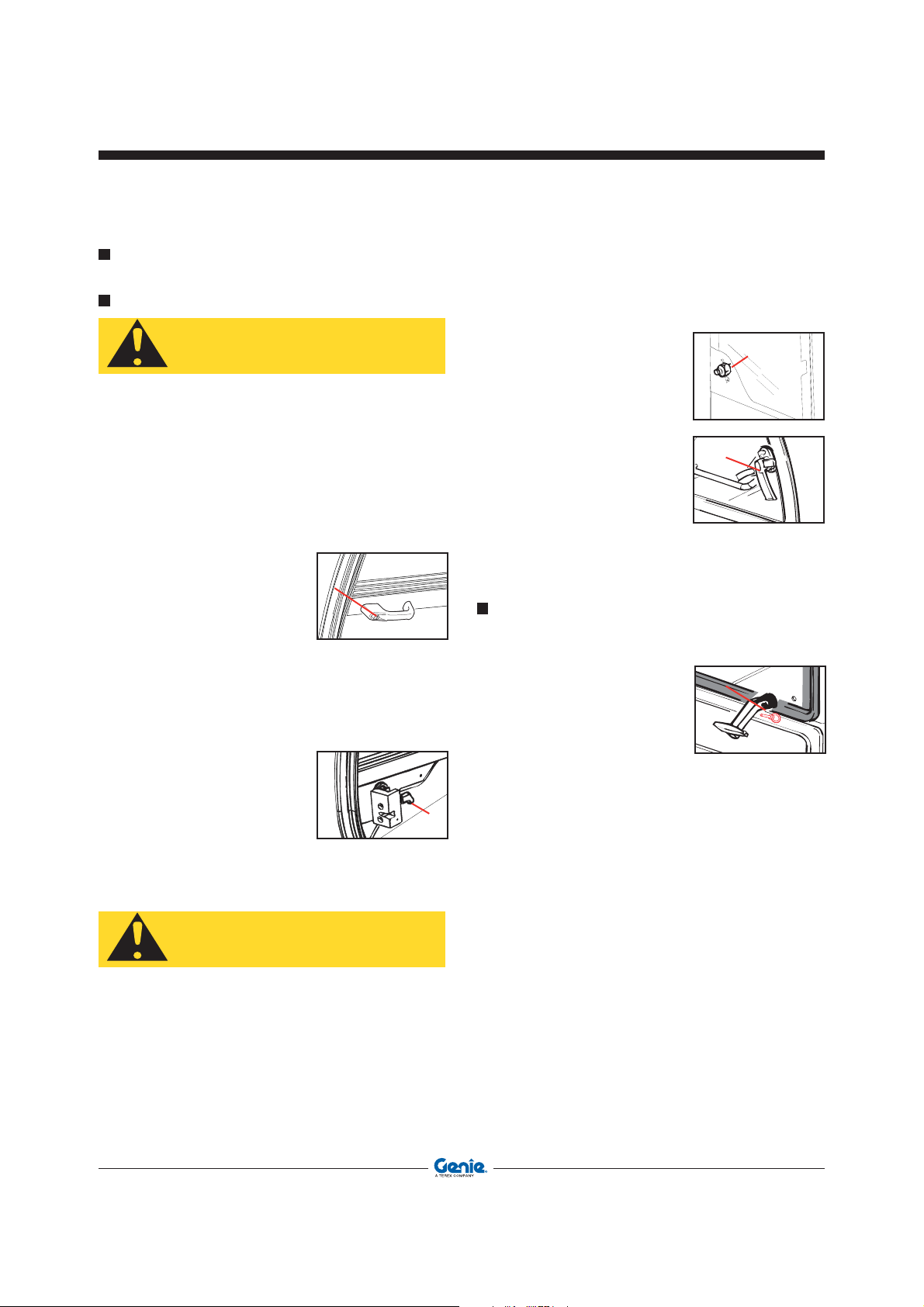
CAUTION
CAUTION
Operator’s Manual First Edition - Third Printing
Operating Instructions
ENTERING THE MACHINE
ENTERING THE CAB
Always make sure that your hands and shoe soles
are clean and dry before getting into the driving
cab. Always face the machine when entering and
leaving it and hold to the suitable handles.
The handler cab is equipped with an access door
on the left-hand side.
Door opening from outside:
• Insert the key and release
lock 1.
• Press the pushbutton 1
and open the door.
Door closing from inside:
Pull the door with force: it locks automatically.
Door opening from inside:
• Lower lever 2 and release
the lock to open the door
completely.
• Rotate handle 3 to open
the upper section of the
door and lock it against the
special catch.
To unlock the door latched in open position:
• Press button 4to unlock
the door from the catch
• Once released, re-close
the upper section of the
door by means of handle
3.
Leaving the cab in an emergency
In an emergency, use the rear
window of the cab as safety
exit-way.
This window has special
locking handles with plastic
pins 5 easy to pull out when
you need to fully open the
glass.
The upper section of the door must be secured
to the rear part of the driving cab or latched to
the lower section of the same door.
62 GTH-4518ER - GTH-4020ER - GTH-6025ER Part No. 57.0009.0404
Page 63
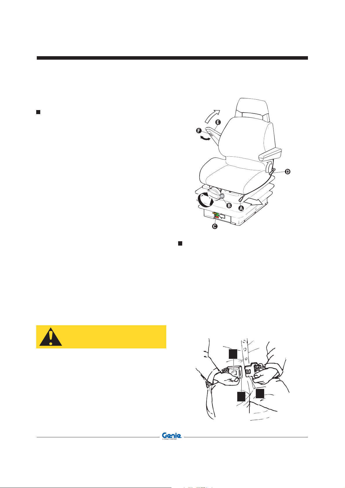
ADJUSTING THE SEAT
Position the seat so you can comfotarbly reach all
the controls. The handler seat is fitted with devices
which let you adjust the seat springing, height and
distance from the controls, the backrest angle and
the armrest height.
• Adjusting the seat distance from the
controls
To slide the seat forward or back, rotate lever A
and push the seat to the desired direction. Then
release the bar and make sure that the seat locks
in position.
• Adjusting seat height and springing
Free the lever of knob B and turn clockwise or
counter-clockwise until reaching the desired
springing. Once you’are correctly seated in the
seat check that the yellow indicator C is in the
green field.
• Adjusting the backrest angle
Operate lever D, press your back firmly against
the backrest and put the backrest at the angle
you wish, then release the lever.
• Adjusting the armrest height
Raise armrest E and turn wheel F to put the
armrest at the height you want.
Operator’s ManualFirst Edition - Third Printing
Operating Instructions
FASTENING THE SEAT BELTS
Sit correctly in the driving seat; then:
• The safety belts are equipped with reel retractor.
To fasten the belt, pull tab 1 and push it into buckle
2.
• To release the belt, push button 3 and remove
the tab from the buckle.
• Make sure that the buckle is correctly located at
the hip point and not on the stomach.
• Operate the end adjusters to reach the length you
wish and make sure the buckle is always in the
middle.
CAUTION
• The seat is for one person only.
• Don’t adjust the seat when the machine is
moving.
Part No. 57.0009.0404 GTH-4518ER - GTH-4020ER - GTH-6025ER 63
3
2
1
Page 64
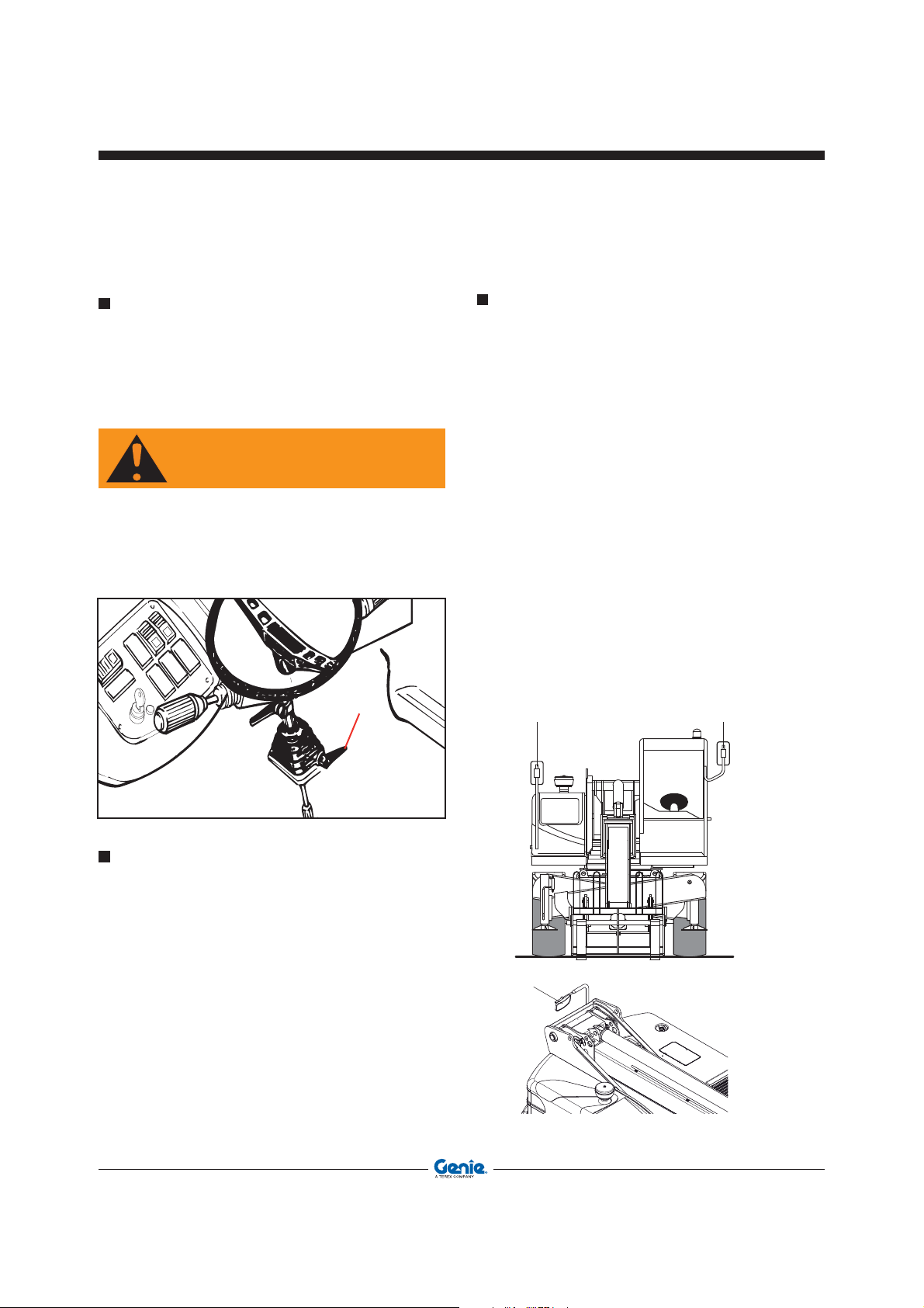
WARNING
Operator’s Manual First Edition - Third Printing
Operating Instructions
ADJUSTING THE STEERING COLUMN
Both steering column and dashboard can be set to
a different angle.
To adjust the steering wheel angle, unlock lever 1
and pull or push the steering wheel to the required
position, then re-lock lever 1.
Before driving the machine, ensure the steering
wheel is perfectly clamped.
ADJUSTING THE REAR VIEW MIRRORS
The machine is fitted with three rear view mirrors:
• Rear view mirror 1 is located on a special
supporting bracket in advanced position and
allows checking the area behind the machine,
on the right-hand side. To adjust its position,
manually rotate the joint it is fitted with.
• Rear view mirror 2 is placed on the left upper
post of the windscreen and allows checking the
area behind the machine, on the left-hand side.
To adjust its position, manually rotate the joint it
is fitted with.
• Rear view mirror 3 is placed on a special bracket
located at the back of the boom and allows
checking the area behind the machine as well
as the rear right stabilizer. To adjust its position,
manually rotate the joint it is fitted with.
SWITCHING ON THE CAB INTERIOR LAMP
The cab ceiling fitting A has a three-position switch
B which lets you:
switch on the interior light
• press the bottom of the switch to switch on the
interior light
switch off the light
• press the switch to the central position to switch
off the light
switch on the interior light when the door is
opened
• press the top of the switch to switch the interior
light on/off when the door is opened/closed.
64 GTH-4518ER - GTH-4020ER - GTH-6025ER Part No. 57.0009.0404
Page 65
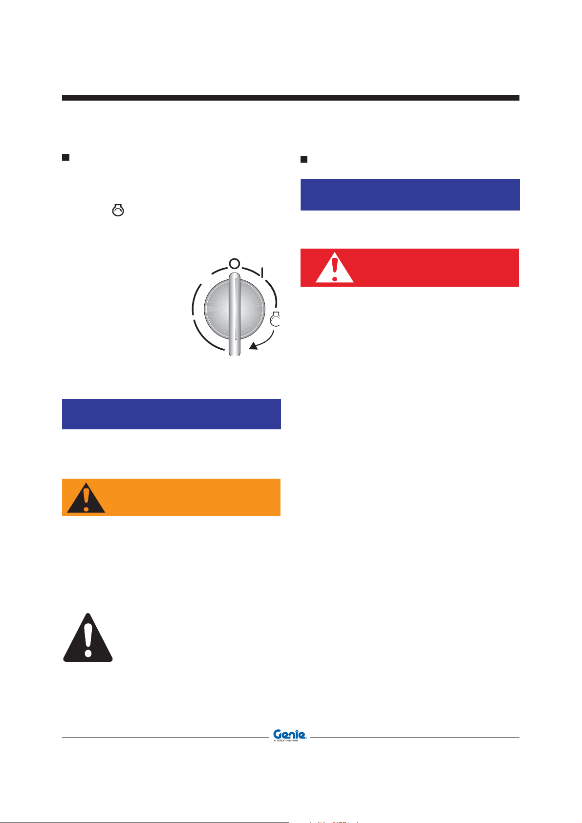
NOTICE
NOTICE
Operator’s ManualFirst Edition - Third Printing
Operating Instructions
STARTING THE ENGINE
• Set the forward/back speed lever to neutral
position.
• To start the engine, rotate the ignition switch to
position , and release when the engine starts.
If the engine does not start within 20 seconds,
release the key and wait at least 2 minutes before
attempting again.
• After the engine starting,
slow down the rpm and
wait some seconds
before engaging a
gear; this allows for a
gradual warm up of the
engine oil and a better
lubrication.
• In case of engine jumpstarting, remove the
connecting cables (see following chapter).
If the light indicators do not switch off/on when
engine is running, immediately stop the machine
and find and rectify the fault.
JUMP-STARTING THE ENGINE
Do not start the engine using a quick charge
booster to avoid any damage to the electronic
boards.
DANGER
When jump-starting the engine through the
battery of another machine, make sure that the
two vehicles cannot collide to prevent formation
of sparks. Batteries give off a flammable gas and
sparks may burn it and cause an explosion
Do not smoke when checking the electrolyte
level.
Keep any metal object like buckles, watch
straps, etc. clear of the battery positive (+)
terminal. These elements can short between
the terminal and nearby metal work and the
operator can get burned.
The booster supply must have the same rated
voltage and output of the battery installed on
the handler.
To jump-start the engine:
WARNING
Once it has been started, the engine continues to
run even if you leave the driving place. DO NOT
LEAVE THE DRIVING PLACE BEFORE HAVING
SHUT THE ENGINE DOWN, LOWERED THE BOOM
TO THE GROUND, TURNED THE SPEED SWITCH
TO THE NEUTRAL POSITION AND ENGAGED
THE PARKING BRAKE.
Engine can not be started if the speed switch is
not in the neutral position.
Part No. 57.0009.0404 GTH-4518ER - GTH-4020ER - GTH-6025ER 65
• Turn any users off by the special control levers.
• Put the gear lever to neutral and engage the
parking brake.
• Ensure the machine battery A is connected to
the frame earth, the terminals are well tightened
and the electrolyte level is regular.
• Connect the two batteries as shown in the
figure. Connect first the positive terminals of the
two batteries, then the negative terminal of the
booster supply B to the machine frame earth.
• If the booster supply is installed on a second
vehicle, make sure that the latter does not touch
the handler. To avoid damage to the electronic
instruments of the machine, the engine of
the machine where the booster supply is
installed, must be stopped.
Page 66
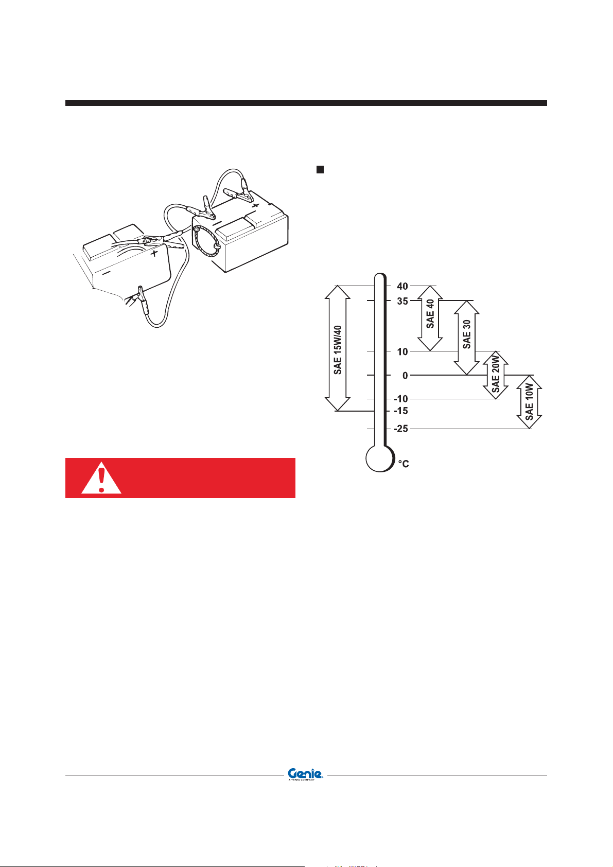
Operator’s Manual First Edition - Third Printing
Operating Instructions
LOW TEMPERATURE STARTING
In case of cold starting, use an oil with a SAE viscosity
adequate to the ambient temperature.
Please refer to the engine use and maintenance
manual.
The machine is supplied with oil SAE 15W/40.
• Turn the ignition key and start the handler.
• Disconnect the cables. Remove first the negative
terminal from the frame earth, then from the
booster supply. Disconnect the positive terminal
from the machine battery, then from the booster
supply.
DANGER
Use only a 12V battery; other devices like battery
chargers, etc. may cause an explosion of the
battery or result in damage to the electrical
system.
66 GTH-4518ER - GTH-4020ER - GTH-6025ER Part No. 57.0009.0404
To start the engine from cold, proceed as follows:
• Set the forward/back speed lever to neutral
position.
• Turn the ignition switch to the glow plugs
preheating position: the relevant warning light 46
goes on. Step down on the gas pedal and start
the engine by turning the ignition switch. Release
the switch as soon as the engine fires.
• Let the engine run at idle for a few seconds before
putting a gear; this allows for a gradual warm up
of the engine oil and a better lubrication.
Page 67

Operator’s ManualFirst Edition - Third Printing
Operating Instructions
STARTING THE MACHINE
When the engine reaches the running temperature,
ensure all parts are in transfer position and the gearbox
lever is in neutral. Then, proceed as follows:
• Select the required steering mode.
• Select the required gear (forward or reverse).
• Release the parking brake.
• Slowly step on the gas pedal to start moving
off.
WARNING
Do not operate the forward/reverse gear lever
when the machine is running. The machine would
reverse the running direction abruptly and you
could seriously be injured.
STOPPING AND PARKING THE MACHINE
When possible, stop the machine on a dry, level and
solid ground. Then:
• Bring the machine to a smooth stop by easing up
the gas pedal and stepping down on the brake
pedal.
• Set the forward/back speed lever to neutral
position.
• Engage the parking brake and ensure its indicator
light switches on.
• Release the service brake pedal.
• Rest the attachment coupled to the boom flat on
the ground.
• Rotate the ignition key to “0” and remove the
key.
• Leave the driving cab and lock the cab door.
WARNING
Always face the machine when getting off the
driving cab; make sure that your hands and
shoe soles are clean and dry, and hold to the
handholds to prevent falls or slips.
WARNING
Always engage the parking brake after stopping
the machine to prevent possible accidental
motions of the vehicle.
Part No. 57.0009.0404 GTH-4518ER - GTH-4020ER - GTH-6025ER 67
Page 68

Operating Instructions
Operator’s Manual First Edition - Third Printing
USING THE LOAD CHARTS
The charts 1 indicating the maximum permissible
load in relation to the boom extension and the type of
attachment used are installed on the cab windscreen
and/or illustrated in the quick guide. The different
charts dipending on the use or not of the outriggers
and on the position of the turntable. To operate under
safe conditions, always refer to these charts.
The extension level of the boom can be checked
with the help of the letters (A, B, C, D, E) painted
on the same boom (pos.2) and compared with the
load chart.
The tag 3 located at the top of each load chart,
indicates the type of attachment used.
The load charts applied on the cab windscreen
refer to a stationary machine standing on a solid
and level ground.
Raise the load some centimetres and check its
stability before raising it completely.
WARNING
GTH-4013 EX - SX
The load charts illustrated in this manual are given
only as a mere example. To define the payload
limits, refer to the load charts applied within the
cab of your machine.
A
09.4618.0866
B
68 GTH-4518ER - GTH-4020ER - GTH-6025ER Part No. 57.0009.0404
Page 69

11 _ LOAD LIMITER
At the back of the driving place there is a unit which
lets you manage the moment limiting system of the
machine.
The collected data, processed in relation to the
attachment used, are continuously compared with the
data stored in the program memory. The processing
of these data results in three different situations which
are displayed by the load limiter display located at
the top right corner.
1 Green LED ON
Stability condition. The raised load does not
exceed 90% of maximum allowed load of the
chart in that defined working position.
2 Yellow LED ON
Pre-alarm condition. The raised load exceeds
90% of maximum allowed load, but it is still inferior
to it. The buzzer emits an intermittent sound.
3 Red LED ON
Alarm condition. The raised load exceeds the
maximum allowed load, the buzzer emits a
continuous sound and the machine motions are
stopped, but for those allowing to return the load
within safety limits.
Operator’s ManualFirst Edition - Third Printing
Operating Instructions
The display of the limiting device is divided into four
areas:
LT area: operating modes
1 Front operation with stabilizers
2 Side operation with stabilizers
3 Front operation without stabilizers
4 Side operation without stabilizers
LED’s area: Three LED’s warn of the variation of
the working condition:
1 green LED - machine stable
2 yellow LED - machine in pre-alarm
3 red LED - machine in alarm
Display area and control keys
Display B Indicates the weight raised for the
system calibration
C Indicates the max. load that can be
raised
D Indicates the distance of the load from
the slewring axis
E Indicates the operating mode (1-2-3-
4)
F Indicates the attachment used (F-P-W-
J-R)
ENTER
Part No. 57.0009.0404 GTH-4518ER - GTH-4020ER - GTH-6025ER 69
Page 70
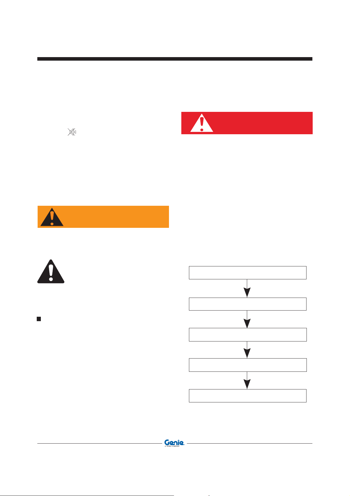
WARNING
DANGER
Operating Instructions
Operator’s Manual First Edition - Third Printing
Keys INDEX To change the operating mode I
(E in the display).
ENTER To confirm.
To set the buzzer off.
Buzzer is reset automatically to on in
an alarm or pre-alarm condition.
I area: attachments
F Pallet fork
P Platform
W Winch
J Extension jib
R Robot
The automatic recognition system of some
attachments is a mere help for the operator who
must, in any case, verify that the attachment on
the display is the one actually in use.
When using an attachment other than those stated
above, but supplied by TEREXLIFT, select the
F - pallet fork operation mode.
Before using the machine, make sure that the first
green LED is ON, and that the operating mode
shown in window E and the attachment shown
in window F are those actually used.
The moment limiter must not be used to check
the load to be handled: it has only been designed
to alert the operator to instable conditions of the
machine during lifting.
Such instable conditions may also be caused by
an abrupt operation of the control lever during
the load handling. If, during work, several LED’s
switch on simultaneously, operate the levers
more smoothly.
Examples of use of the overload warning system
Boom extension without stabilizers
Overload warning system in alarm
Operation
At the machine starting, the overload warning system
runs an automatic check.
After about 10 seconds, the date and the machine
model are displayed followed by the first page showing
the last attachment used or the new attachment with
electrical recognition.
Once the automatic diagnosis is completed, the
machine is ready for use.
If the attachment used is of “mechanical” type, proceed
with the manual search and selection. Press INDEX
until the letter corresponding to the used attachment
is displayed in the F window.
Press ENTER to confirm.
The machine is ready to use.
70 GTH-4518ER - GTH-4020ER - GTH-6025ER Part No. 57.0009.0404
Boom retraction - Alarm ceases
Stabilizers at work
Boom extension
Page 71

HANDLING LOADS
WARNING
Adjusting the forks
With FEM forks
Forks shall be spaced to suit the load going to be
handled. For this purpose:
• Lift the clamping lever of the forks.
• Slide the forks to the desired position, then re-lock
the lever.
With floating forks
In the case of floating forks:
• Loosen the nut
of the locking
screws.
• Raise the forks
and slide them
on the pivot
until correct
spacing.
• Lock the
screws retightening the
nut.
Operator’s ManualFirst Edition - Third Printing
Operating Instructions
• The centre of gravity of the load must always
be halfway between the forks.
• Ensure you exactly know the weight of the
load before handling it.
• When extending the boom, do not exceed the
payload limit.
• Refer to the payload limits given in the load
chart applied on the cab windscreen or in the
quick user’s guide.
• Space the forks as wide as possible to suit
the load being handled.
Part No. 57.0009.0404 GTH-4518ER - GTH-4020ER - GTH-6025ER 71
Page 72

DANGER
Operating Instructions
Operator’s Manual First Edition - Third Printing
WORKING PHASES
When forks are correctly spaced, the handler is
ready to use.
Work can be subdivided into three different phases:
loading, transfer and unloading.
Loading phase
• Approach the load to the handled perpendicularly
and check that the machine is level on the
inclinometer.
• Insert the forks under the load and raise the load
some centimetres.
• Pitch the forks back to retract the load.
Transfer phase
• Do not start or brake abruptly.
• Drive to the unloading point cautiously and keep
the load 20÷30 cm from the ground.
• Suit the machine speed to the ground conditions
to avoid dangerous jumps, side skids of the
vehicle and possible load falls.
• When driving on slopes or ramps, hold the load
uphill.
• When the forks are clear of the load, set them to
transfer position.
• Release the parking brake and start a new
working cycle.
WARNING
Do not move off when the load is raised 20÷30 cm
above the ground. Risk of machine overturning
or load fall.
Do not drive on slopes sideways; this wrong
manoeuvre is one of the main reasons for
accidents due to vehicle overturning.
Unloading phase
• Drive to the unloading point with straight wheels
and bring the machine to a smooth stop leaving
enough space to operate the boom.
• Put the parking brake and set the transmission
to neutral.
• Position the load some centimetres above the
desired position and set the forks level.
• Lower the load and make sure it is level.
• Carefully withdraw the forks by operating the
boom retraction control and, if necessary, raise
or lower the boom as forks come out.
72 GTH-4518ER - GTH-4020ER - GTH-6025ER Part No. 57.0009.0404
Page 73
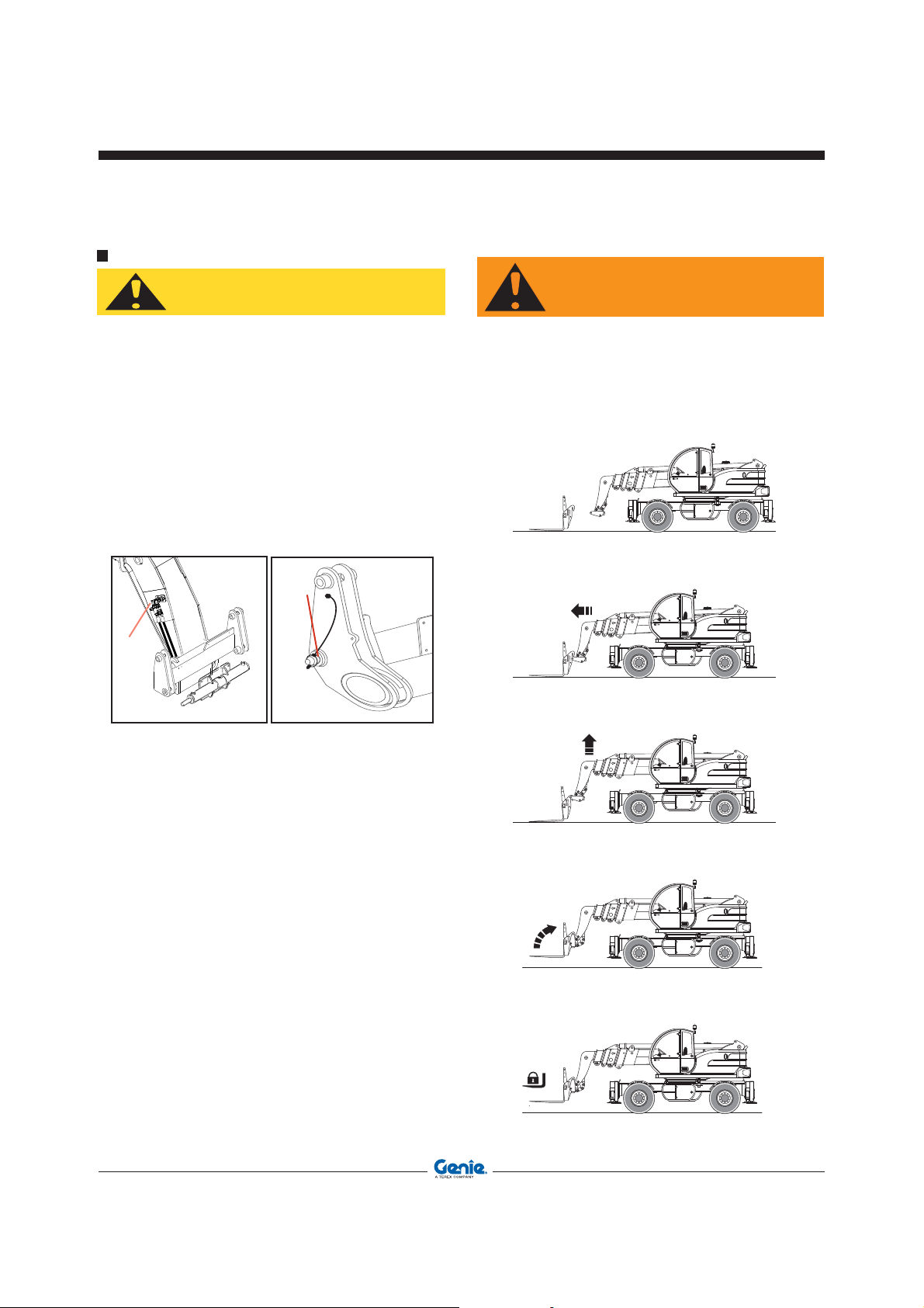
CHANGING THE ATTACHMENT
CAUTION
Operator’s ManualFirst Edition - Third Printing
Operating Instructions
WARNING
Use only attachments directly manufactured or
recommended by Terexlift and detailed in the
”Optional Attachments” section.
Version with HYDRAULIC LOCKING
To change an attachment, operate as follows:
• Drive to the place where you will release the
mounted attachment (when possible, a solid and
sheltered site).
• Disconnect the quick connectors of the attachment
(if any), and connect the hydraulic locking pipes
of the attachments to couplings 1.
• Rest the attachment flat on the ground.
• Remove the safety pin 2 placed at its end.
• Free the attachment operating the control of the
attachment locking/unlocking cylinder
• Pitch the attachment holding frame forward and
lower the boom to release the attachment upper
lock.
• Move back with the machine and drive to the new
attachment to be coupled.
• Hold the frame pitched forward and hook the
upper lock of the new attachment.
• Retract and raise the attachment some
centimetres. It will centre automatically on the
quick coupling frame.
• Operate the attachment locking joystick and
secure the attachment in place with safety pin 2
previously removed.
• Re-couple the connectors of the attachment (if
any).
After substitution, visually check the attachment
is correctly coupled to the boom, before operating
the machine. A wrongly coupled attachment may
result in damage to persons or things.
Part No. 57.0009.0404 GTH-4518ER - GTH-4020ER - GTH-6025ER 73
Page 74
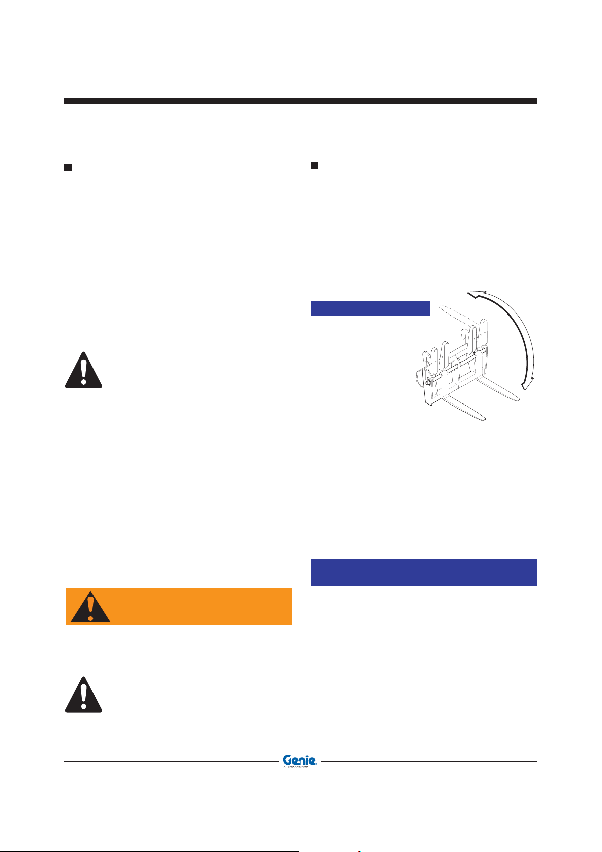
NOTICE
NOTICE
WARNING
Operating Instructions
Operator’s Manual First Edition - Third Printing
USE OF THE MAN-PLATFORM
For the use of the man-platform, proceed as
follows:
1. Couple the man-platform to the attachment
holding frame.
2. Fully extend the stabilizers.
3. Completly lower the stabilizers and sway the
machine; check the operation on the inclinometer
24 in the cab.
4. Unlock the rotation of the counter-frame/
turntable.
5. Level the platform floor.
The platform floor cannot be levelled once the
controls have been switched from the driving
cabin to the platform. Before starting using the
platform, make sure the floor is level.
6. Turn the ignition switch to I position.
7. Turn the cab/road/platform switch to the “Platform”
position (the green LED comes on).
8. Remove the key from the cab/road/platform switch
to use it for the platform controls.
9. Open the protection cover of the power socket on
the boom and plug in the platform plug.
10. Enter the man-platform and insert the key,
previously removed, in the controls switch.
ROAD OR SITE TRANSFER
When travelling on public roads, strictly obey the
local or national road traffic regulations.
Besides, take into account the following general
precautions:
• Align the rear wheels.
• Sway the machine.
• Cover the teeth of the conventional forks with the
special guard; or withdraw the floating forks.
With the floating
forks pitched back,
do not move the fork
pitching cylinder as
the machine could
suffer from damage.
• Retract boom and attachment to transfer
position.
• Set the Road/Jobsite/Platform to “ROAD”.
• Make sure that lights, horn and turn signals are
in working order.
• Engage the gear.
• The transfer speed of the vehicle will depend on
the engine rpm and the position of the control
lever.
If the platform controls remain disabled after
the key insertion, check the correct position of
the sensors controlling the attachments and
stabilizers connecting pin.
For the use and maintenance of the man-platform,
read the specific manual - code 57.0302.9200.
74 GTH-4518ER - GTH-4020ER - GTH-6025ER Part No. 57.0009.0404
Public road circulation is allowed only for
transferring an unloaded machine.
Do not use the machine to tow trailers.
Page 75
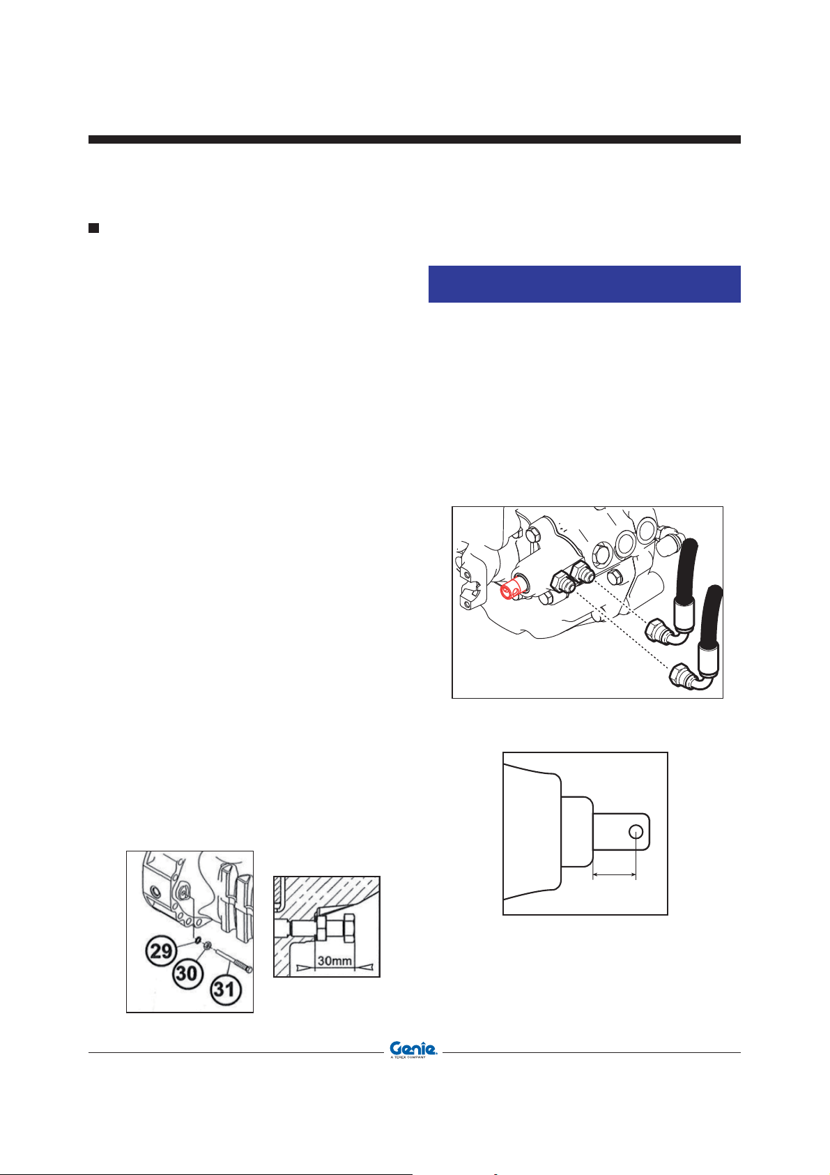
MOVING A DISABLED MACHINE
L
NOTICE
Tow the machine only when no alternative is possible,
since this operation may result in serious damage to
the transmission. When possible, repair the machine
on site.
When the machine shall absolutely be towed:
• Unlock the parking brake.
• Tow the machine for short distances and at a low
speed only (less than 5 km/h).
• Use a rigid drawbar.
• Select the two-wheel steer.
• Set the forward/back speed lever to neutral
position.
• Put the gearbox lever to neutral (see below)
• Raise the front wheels of the machine.
• When possible, start the engine and use the
hydraulic drive and the braking system.
Operator’s ManualFirst Edition - Third Printing
Transporting The Machine
Setting the gear lever in neutral
Do not tow the machine without setting the mechanical gear lever to neutral position.
To set the gear lever to neutral:
• Disconnect the cylinder hoses A and B.
• Pry the cursor of the gearbox lever C to neutral
position (L = 20 mm).
• Riconnect the cylinder hoses A and B.
Unlocking the negative brake
To unlock the negative brake of a faulty machine,
use the four screws 31 on the two sides of the front
differential casing as follows:
• Loosen the four counter-nuts fixing screws 31,
then move the nuts backwards by approx. 8
mm.
• Tighten screws 31 so as to fasten them onto the
pressure plate.
• Using a wrench, tighten the screws 31 in an
alternate sequence by 1/4 turn a time so as to
compress the Belleville washers and disengage
the braking disks. Tighten max. by one turn.
• After the manual release, adjust screws 31 to obtain a jut of 30 ± 0.5 mm in relation to the arm.
Part No. 57.0009.0404 GTH-4518ER - GTH-4020ER - GTH-6025ER 75
Page 76

Operator’s Manual First Edition - Third Printing
Transporting The Machine
LIFTING THE MACHINE
When the machine shall be lifted, use only means
having a suitable capacity. The characteristic data
are detailed in the relevant chapter of this manual
and on the identification plate.
For the machine lifting, anchor the chains to the
special lugs on the machine (marked with the decal
below).
TRANSPORTING THE MACHINE ON OTHER
VEHICLES
To transport the machine on another vehicle, follow
the steps below:
• Ensure ramps are correctly positioned.
• Retraact the boom to transfer position.
• Carefully drive the machine onto the transporting
vehicle.
• Put the parking brake and rest the attachment flat
on the vehicle platform.
• Ensure the overall dimensions do not exceed the
allowed limits.
• Shut the engine down and close the driving cab
of the machine.
• Secure the machine to the vehicle platform by
wheel-chocks.
• Anchor the machine to the transporter's platform
by fixing the chains to the special eyebolts on the
chassis.
76 GTH-4518ER - GTH-4020ER - GTH-6025ER Part No. 57.0009.0404
Page 77

PARKING AND STORAGE
CAUTION
NOTICE
Operator’s ManualFirst Edition - Third Printing
Transporting The Machine
Short inactivity
Always park the machine in a safe way after a working
day, a shift and at night.
Take all precautions to prevent damage to those
persons who will approach the machine while
stationary:
• Park the machine so that it does not hinder other
operations.
• Lower the boom fitted with attachment on the
ground.
• Disengage the transmission and put the parking
brake.
• Remove the key from the ignition switch and lock
the cab door.
Leaving a battery connected can result in shorts
and, as a consequence, in a fire.
Machine storage
In case of extended inactivity of the machine, follow
the above precautions. Additionally:
• Wash the machine thoroughly. For a better
cleaning, remove grills and protection casings.
• Carefully dry all machine parts by blowing some
compressed air.
• Lubricate the machine thoroughly.
• Do a walk-around inspection and replace any
worn or damaged part.
• Re-paint any worn or damaged part.
• Remove the battery, smear its terminals with
vaseline and store it in a dry place. Battery can be
used for other purposes. Otherwise, periodically
check its charge level.
• Refuel the tank to prevent internal oxidation.
• Store the machine in a sheltered and wellventilated place.
• Start the engine for about 10 minutes at least
once a month.
• When weather is particularly cold, empty the
radiator.
Always remember that the ordinary maintenance
must be carried out even during the machine
inactivity. Pay particular attention to the fluid
levels and to those parts subject to ageing. Before
re-starting the machine, carry out an extraordinary
maintenance and carefully check all mechanical,
hydraulic and electrical components.
Part No. 57.0009.0404 GTH-4518ER - GTH-4020ER - GTH-6025ER 77
Page 78

NOTICE
NOTICE
PROTECT THE
ENVIRONMENT
PROTECT THE
ENVIRONMENT
Operator’s Manual First Edition - Third Printing
Transporting the machine
CLEANING AND WASHING THE MACHINE
Clean the machine in accordance with the following
instructions:
• Remove any oil or grease traces with a dry
solvent or a volatile mineral alcohol
• Before assembling a new part, remove any
protection product (rust-preventer, grease, wax
etc.).
• Remove any trace of rust from metal parts with
some emery cloth before smearing the part with
a protection product (rust-preventer, paint, oil
etc.).
Do not use water at high pressure for washing
the machine and especially the main valve, the
solenoid valves and electrical parts.
External washing
Before washing the machine, check that the engine is
shut down and the doors and windows are closed.
Do not, at any times, use fuel to clean the machine.
Use water or some steam. In cold climates, dry
the locks after washing or smear them with an
antifreeze.
Before using the machine again, check its
conditions.
Internal washing
Wash the machine interior with some water and a
sponge. Do not use water at high pressure. After
washing, dry with a clean cloth.
Washing the engine
Before washing the engine, protect the air intake filter
to prevent water from entering the circuit.
MACHINE DISPOSAL
At the end of the machine life, call in a specialised
firm to dispose of it in compliance with the local
or national regulations.
Battery disposal
Used lead-acid batteries cannot be disposed
of as normal industrial solid wastes. Because
of the presence of harmful substances, they
must be collected, eliminated and/or recycled in
accordance with the laws of the UE.
Used batteries must be kept in a dry and confined
place. Make sure the battery is dry and the cell
plugs are tight. Place a sign on the battery to
warn of not using it. If before disposal the battery
is left in the open air, it will be necessary to dry,
smear the box and the elements with a coat of
grease and tighten the plugs. Do not rest the
battery on the ground; it is always advisable to
rest it on a pallet and cover it. The disposal of
batteries shall be as rapid as possible.
If the machine shall be used in a marine or
equivalent environment, protect it against salt
deposits with an adequate treatment against
saltiness to prevent rust formation.
78 GTH-4518ER - GTH-4020ER - GTH-6025ER Part No. 57.0009.0404
Page 79

NOTICE
Operator’s ManualFirst Edition - Third Printing
Maintenance
Observe and obey:
* The operator can only perform
the routine maintenance
operations envisaged in this
manual.
* Scheduled maintenance
procedures shall be completed
by qualified technical personnel
according to the manufacturer’s
specifications.
Maintenance symbol legend:
The following symbols are used in this manual
to help you understand better the instructions
provided. When one or more symbols appear at
the beginning of a maintenance procedure, they
indicate the following:
Indicates that tools are required to
perform the procedure.
INTRODUCTION
A thorough and regular maintenance keeps the
machine in a safe and efficient working condition.
For this reason, it is advisable to wash, grease and
service the machine properly, especially after having
worked under particular conditions (muddy or dusty
environments, heavy operations, etc.).
Always ensure all machine components are in good
condition. Check for oil leaks or loosening of guards,
and make sure that the safety devices are efficient.
In case of defects, find and rectify them before using
the machine again.
Not respecting the ordinary maintenance schedule
of this manual automatically voids TEREXLIFT
warranty.
For the engine maintenance, please refer to the
specific Operator handbook supplied with the
machine.
Indicates that new parts are required
to perform the procedure.
Indicates that a cold engine is required
to perform the procedure.
SERVICE INTERVAL
Running-in ____________________________
Ordinary ______________________________
Indicates the time interval for the
maintenance jobs expressed in working
hours.
Part No. 57.0009.0404 GTH-4518ER - GTH-4020ER - GTH-6025ER 79
Page 80

Operator’s Manual First Edition - Third Printing
Maintenance
LUBRICANTS - HEALTH AND
SAFETY PRECAUTIONS
Health
A prolonged skin contact with oil can cause irritation.
Use rubber gloves and protective goggles. After
handling oil, carefully wash your hands with soap
and water.
Storage
Always keep lubricants in a closed place, out of the
children’s reach. Never store lubricants on the open
air and without a label indicating their contents.
Disposal
New or exhausted oil is always polluting! Never
drain oil on the ground. Store new oil in a suitable
warehouse. Pour exhausted oil into cans and deliver
them to specialised firms for disposal.
Oil leaks
In case of accidental oil leaks, cover with sand or
type-approved granulate. Then scrape off and dispose
of it as chemical waste.
First aid
Eyes : In case of accidental contact with
the eyes, wash with fresh water. If
the irritation persists, seek medical
advice.
Intake : In case of oil intake, do not induce
vomiting, but seek medical advice.
Skin : In case of a prolonged contact, wash
with soap and water.
Fire
In case of fire, use carbon dioxide, dry chemical or
foam extinguishers. Do not use water.
80 GTH-4518ER - GTH-4020ER - GTH-6025ER Part No. 57.0009.0404
Page 81

ORDINARY MAINTENANCE
CAUTION
Operator’s ManualFirst Edition - Third Printing
Maintenance
A wrong or neglected maintenance can result in
possible risks for both operator and bystanders.
Make sure maintenance and lubrication are carried
out according to the manufacturer’s instructions to
keep the machine safe and efficient.
The maintenance interventions are based on the
machine working hours. Regularly check the hourmeter and keep it in good conditions to define the
maintenance intervals correctly. Make sure any
defect detected during the maintenance is promptly
rectified before using the machine.
All "" marked operations must be carried out
by a skilled technician.
During the first 10 working hours
1 Check the oil level within reduction and
differential gears
2 Regularly check the tightening of the wheel
bolts
3 Check the tyre inflation
4 Check the tightening of all bolts and nuts
5 Check the couplings for oil leaks
Within the first 50 working hours
1. Grease the sliding parts and the pivot pin of the
telescopic boom
Every 10 working hours or daily
1 Check the engine oil level
2 Clean the air suction filter
3 Clean the air suction pre-filter
4 Remove the dust from the filter by squeezing the
special rubber element on the same filter
5 Check the engine coolant level
6 Clean the radiator, if necessary
7 Check the hydraulic oil level within the
reservoir
8 Make sure that the boom sections are well -
greased close to the sliding pads
9 Grease the counterframe/turntable slewring
10 Grease the attachment holding plate
11 Grease all joints of boom and stabilisers, the
front and rear axle shaft joints, the transmission
shafts and any equipment of the machine
12 Ensure the lighting system is efficient
13 Ensure both braking system and parking brake
are efficient
14 Ensure the differential locking is efficient
15 Ensure the steering selection system is
efficient
16 Ensure the mechanical gear selection system is
efficient
17 Ensure the back/forward selector switch is
efficient
18 Ensure the fork balance system is efficient
19 Make sure the safety devices installed are in
efficient working order
Within the first 250 working hours
1 Grease the sliding parts and the pivot pin of the
telescopic boom
Part No. 57.0009.0404 GTH-4518ER - GTH-4020ER - GTH-6025ER 81
Page 82

Operator’s Manual First Edition - Third Printing
Maintenance
Every 50 working hours or weekly
Jobs to be done in addition to those above.
1 Check the tension of the alternator belt
2 Check the tyre inflation
3 Check the tightening of the wheel nuts
4 Check the tightening of the Cardan shaft
screws
5 Check the tightening of the screws fixing the
counterframe/turntable rotation slewring
6 Check the tightening of the telescope sliding
blocks
7 Check the sleeves connecting the air filter to the
engine cooling system
8 Check the operation of the emergency pump
Every 250 working hours or monthly
Jobs to be done in addition to those above.
1 Change the engine oil and relevant filter
2 Check the oil level in the gearbox
3 Check the oil level in the front and rear differential
gears
4 Check the oil level in the four wheel reduction
gears
5 Check the oil level in the counterframe/turntable
rotation reduction gear
6 Check the condition of the engine air filter.
Replace, if necessary
7 Check the clamping of the cable heads to the
battery terminals
8 Check the condition of the air suction hose
between engine and filter
9 Check the condition of the cylinder chrome-
plated rods
10 Check the hydraulic lines are not worn due to a
rubbing against the frame or other mechanical
components
11 Ensure electrical cables do not rub against the
frame or other mechanical components
12 Check the wear of the sliding pads of the boom
sections
13 Adjust the clearance of the sliding pads of
the boom sections
14 Adjust the parking brake
15 Check the level of the battery electrolyte
Every 3 working months
1 Check the efficiency of the block valves
Every 500 working hours or every two months
Jobs to be done in addition to those above.
1 Visually check the quantity of smoke from the
engine exhaust
2 Check the tightening of the engine fixing
screws
3 Check the tightening of the cab fixing screws
4 Check the backlash between pins and bushings
in all joints
5 Check the clearance of the slewring
6 Change the engine air filtering element
7 Change the engine Diesel-oil filter
8 Change the hydraulic oil filter of the
transmission
9 Have the hydraulic system checked by a qualified
technician
Every 1000 working hours or every six months
Jobs to be done in addition to those above.
1 Change the oil in the front and rear differential
gears
2 Change the oil in the gearbox
3 Change the oil in the counterframe/turntable
rotation reduction gear
4 Change the oil in the four wheel reduction
gears
5 Change the hydraulic oil
6 Remove any grease from the boom, then re-
grease the sliding parts of the boom sections.
7 Clean or replace, if nececessary, the air filter in the
cab
8 Grease the sliding parts and the pivot pin of the
telescopic boom
82 GTH-4518ER - GTH-4020ER - GTH-6025ER Part No. 57.0009.0404
Page 83

Every 2000 working hours or yearly
Jobs to be done in addition to those above.
1 Change the engine coolant
Every 6000 hours or 5 years and, subsequently,
every 2 years
Jobs to be done in addition to those above.
1 Check that the structure is intact paying a special
attention to the welded supporting joints and the
boom pins.
Operator’s ManualFirst Edition - Third Printing
Maintenance
OIL CHANGE SCHEDULE
Job
Oil level check
Engine
Axles
and
power
divider
Hydraulic
oil
Turntable
rotation
reduction
gear
* whichever occurs fi rst.
First change
Subsequent changes
Oil level check
First change
Subsequent changes
Oil level check
First change
Subsequent changes
Oil level check 250 monthly SHELL OMALA 150
First change - Subsequent changes 1000 6 month
Operating
hours *
10
500 500
250
--
1000
10
--
1000 6 month
Service
interval *
daily
yearly
monthly
yearly
daily
Oil type
SHELL RIMULA 15W-40
(API CH-4/CG-4/CF-4/CF;
ACEA E3; MB228.3)
TRACTORENAULT THFI 208
LF SAE 80W; API GL4 / FORD
M2C 86B; MASSEY FERGUSON M 1135
SHELL TELLUS T 46
DENISON HF-1, DIN 51524
part 2 & 3
DN 51 517-3 CLP, ISO 122951 TYPE CKC, US STEEL 224,
DAVID BROWN 51.53.101
Part No. 57.0009.0404 GTH-4518ER - GTH-4020ER - GTH-6025ER 83
Page 84

CAUTION
CAUTION
Operator’s Manual First Edition - Third Printing
Maintenance
MAINTENANCE INTERVENTIONS
WARNING
All maintenance interventions must be carried
out with engine stopped, parking brake engaged,
working attachments flat on the ground and gear
lever in neutral.
WARNING
When raising a component for maintenance
purposes, secure it in a safe way before any
maintenance intervention.
WARNING
Any intervention on the hydraulic circuit must
be carried out by skilled personnel.
The hydraulic circuit of this machine is fitted
with pressure accumulators. You and others
could be seriously injured if accumulators are
not completely depressurised.
For this purpose, shut the engine down and step
on the brake pedal 8/10 times.
High pressure lines must be replaced by qualified
personnel only.
Any foreign matters entering the closed circuit
may result in a sudden deterioration of the
transmission.
The qualified staff charged with the maintenance
of the hydraulic circuit must clean all areas around
with care before any intervention.
PROTECT THE
ENVIRONMENT
The handling and disposing of used oils can be
ruled by local or national regulations. Address
to authorised centres.
WARNING
Before any operation on hydraulic lines or
components, make sure there is no residual
pressure. For this purpose, stop the engine,
engage the parking brake and operate the
control levers of the main valve in both working
directions (alternately) to depressurise the
hydraulic circuit.
84 GTH-4518ER - GTH-4020ER - GTH-6025ER Part No. 57.0009.0404
Page 85

ACCESS TO THE ENGINE COMPARTMENT
CAUTION
For any operation within the engine compartment,
open the protection bonnet.
The bonnet is equipped with pneumatic shock
absorbers which unburdens and hold the bonnet in
raised position. To open the bonnet:
• Shut the engine down and put the parking
brake.
• Turn the key to unlock and open the bonnet.
Operator’s ManualFirst Edition - Third Printing
Maintenance
Take all precautions when
approaching the engine compartment.
Some parts of the engine may be very
hot. Always use protective gloves.
Part No. 57.0009.0404 GTH-4518ER - GTH-4020ER - GTH-6025ER 85
Page 86

NOTICE
NOTICE
Operator’s Manual First Edition - Third Printing
Maintenance
ENGINE AIR FILTER
(FOR GTH-4518 ER - GTH-4020 ER)
Clean the engine air filter and replace the elements,
when necessary.
1 Cleaning and changing the outer element:
- Raise the boom and secure it in a stable and safe
way.
- Shut the engine down and engage the parking
brake.
- Unscrew wing nut A and remove cover B.
- Remove the outer element C.
- Clean the filter bowl.
- Dry clean the cartridge (at max. 6 bar pressure)
and direct the air jet from inside to outside.
- Check the filter element for cracks by introducing
a lamp inside.
- Smear the seal with grease, then refit the
element.
- Close cover B and tighten it with wing nut A.
Make sure that the rubber element E is oriented
downwards..
3 Changing the cyclone pre-filter
Daily clean the cyclone pre-filter:
- Shut the engine down and engage the parking
brake.
- Loosen wing nut F and remove cover G.
- Remove the dust container and empty it.
- Refit the dust container and the cover and tighten
the wing nuts.
As soon as the indicator light 6.8 switches on,
replace the outer element.
2 Changing the inner element
- See step 1 for removing the outer element.
- Remove the inner element D.
- Clean the filter bowl.
- Smear the seal with grease, then fit the
new element and make sure it is correctly
positioned.
- To refit the outer element and the cover, see step
1.
Running-in _____________________________ None
Cleaning _____________________ Every 10 hours
Outer element change __________Every
The inner element should be replaced every two
times the outer element is replaced.
86 GTH-4518ER - GTH-4020ER - GTH-6025ER Part No. 57.0009.0404
Inner element change ________ Every 1000 hours
SERVICE INTERVAL
500 hours
Page 87

ENGINE AIR FILTER
NOTICE
(FOR GTH-6025 ER)
Clean the engine air filter and replace the elements,
when necessary.
1 Cleaning and changing the outer element:
- Raise the boom and secure it in a stable and safe
way.
- Shut the engine down and engage the parking
brake.
- Unlock the three clamps A of the filter cover B.
- Remove the outer element C.
- Clean the filter bowl.
- Dry clean the cartridge (at max. 6 bar pressure)
and direct the air jet from inside to outside.
- Check the filter element for cracks by introducing
a lamp inside.
- Smear the seal with grease, then refit the
element.
- Refit cover B and lock it with the special clamps.
Make sure that the rubber element D is oriented
downwards..
Operator’s ManualFirst Edition - Third Printing
Maintenance
As soon as the indicator light 6.8 switches on,
replace the outer element.
2 Changing the cyclone pre-filter
Daily clean the cyclone pre-filter:
- Shut the engine down and engage the parking
brake.
- Loosen wing nut E and remove cover F.
- Remove the dust container and empty it.
- Refit the dust container and the cover and tighten
the wing nuts.
Part No. 57.0009.0404 GTH-4518ER - GTH-4020ER - GTH-6025ER 87
Running-in _____________________________ None
Cleaning _____________________ Every 10 hours
Outer element change __________Every 500 hours
Inner element change ________ Every 1000 hours
SERVICE INTERVAL
Page 88

CAUTION
Operator’s Manual First Edition - Third Printing
Maintenance
ENGINE COOLING SYSTEM
When the coolant is hot, the cooling system
is under pressure. With warm engine, loosen
the radiator plug slowly and carefully, without
removing it, to drain the pressure. Use protection
gloves and keep your face at a safe distance.
• Weekly check the coolant level within pan A
before starting working (when coolant is cold).
• When necessary, add clean water or an antifreeze
mixture through cap B.
• Change the antifreeze mixture every two years.
To drain the antifreeze:
- Let the engine cool down.
- Unscrew the plug C at the bottom of the radia-
tor. Allow the coolant to flow out into a special
container.
- Once the coolant has been drained, refit plug
C and pour fresh mixture (50% water and 50%
antifreeze) in the radiator. This proportion will
provide protection down to -38°C.
• Daily clean the radiator grille using a brush with
hard bristles or compressed air at a max pressure
of 6 bar.
On delivery, the machine is filled with a cooling mixture
consisting of 50% water and 50% anti-freeze.
TEREX PRO COOL
Protection against boiling / freezing
Product % Freezing point Boiling point
33
40
50
70
SERVICE INTERVAL
Running-in
Ordinary
88 GTH-4518ER - GTH-4020ER - GTH-6025ER Part No. 57.0009.0404
__________________________ None
__________________ Every 50 hours
-17°C
-24°C
-36°C
-67°C
123°C
126°C
128°C
135°C
Page 89

CAUTION
PROTECT THE
ENVIRONMENT
Operator’s ManualFirst Edition - Third Printing
Maintenance
CHECKING THE OIL LEVEL IN THE TANK
Fine jets of hydraulic oil under pressure can
penetrate the skin. Do not use your fingers, but
a piece of cardboard to detect oil leaks.
Check the hydraulic oil level (visually) through the
special level A fitted into the tank.
When necessary, add new oil through filler B.
SERVICE INTERVAL
Running-in
Ordinary
Handling and disposal of exhausted oils may be
ruled by local or national regulations. Dispose of
the exhausted oils through the special authorised
centres.
_________Within the first 10 hours
__________________ Every 50 hours
CHANGING THE HYDRAULIC OIL
1 Stop the machine on a level ground and make
sure the parking brake is engaged.
2 Release the pressure from the hydraulic circuit.
3 Place a container of suitable size under the drain
plug C, placed in the lower part of the reservoir,
and collect any oil leaks.
4 Remove the drain plug C and allow oil to flow out
into the container.
5 Refit the drain plug C.
6 Add new oil by making sure that it matches the
recommended type until it is level with A.
SERVICE INTERVAL
Running-in_________________________None
Ordinary_______________Every 1000 hours
Part No. 57.0009.0404 GTH-4518ER - GTH-4020ER - GTH-6025ER 89
Page 90

NOTICE
NOTICE
PROTECT THE
ENVIRONMENT
Operator’s Manual First Edition - Third Printing
Maintenance
CHANGING THE OIL FILTER CARTRIDGE
To change the hydraulic oil filter element, proceed
as follows:
1
Stop the machine on a level ground and engage
the parking brake.
2
Place a container of suitable size under the filter to
collect any oil leaks
3
Remove the filter cover to get access to the filter
element A
4
Change the filter element, then, before fitting a new
one, thoroughly clean and grease both seat and
gasket
5
Refit and tighten the filter cover
.
.
.
.
The hydraulic oil filter cartridge shall be replaced
as soon as the warning light 6.7 comes on (see
par. Controls and instruments).
Hydraulic oil filter canisters cannot be cleaned
or washed and refitted.
They must be replaced with new ones of the type
recommended by the manufacturer.
The handling and disposing of used oils may be
ruled by local or national regulations. Address
to authorised centres.
SERVICE INTERVAL
Running-in
__________________________ None
Ordinary
90 GTH-4518ER - GTH-4020ER - GTH-6025ER Part No. 57.0009.0404
_________________ Every 500 hours
Page 91

CAB AIR FILTER
NOTICE
Every six months clean the air filter in the cab. Replace
the cartridge if the filtering cloth is damged.
1 Cleaning and changing the cartridge:
- Shut the engine down and engage the parking
brake.
- Pull filter A out of the housing accessible from
the outside of the cab.
- Clean the filter bowl.
- Clean the filter cartridge by beating it against
a piece of wood. Replace the cartridge if
damaged.
Operator’s ManualFirst Edition - Third Printing
Maintenance
Paper filters must never be cleaned using
compressed air or washed with water and/or
solvents.
Part No. 57.0009.0404 GTH-4518ER - GTH-4020ER - GTH-6025ER 91
Page 92
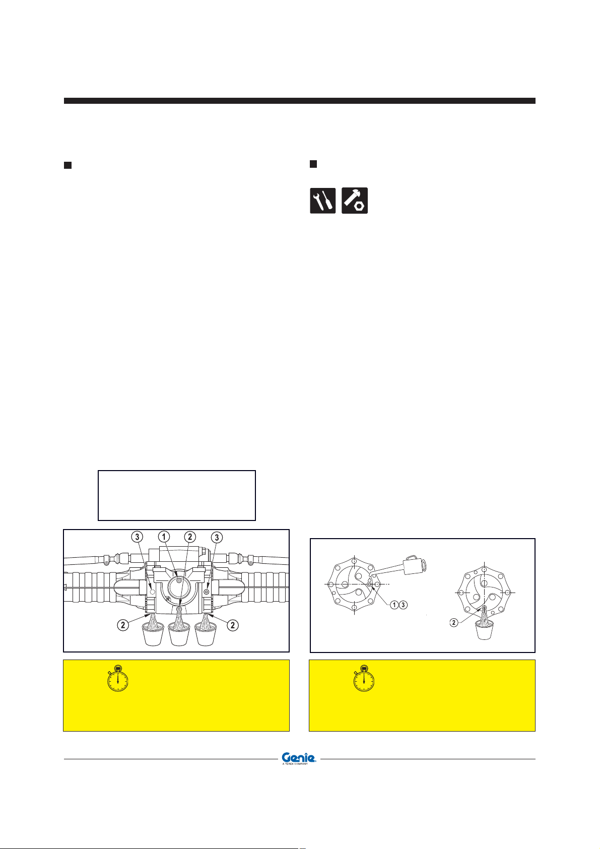
Operator’s Manual First Edition - Third Printing
Maintenance
OIL LEVEL IN THE DIFFERENTIAL GEARS
To check the oil level in the front and rear differential
gears:
• Stop the machine on a level ground and engage
the parking brake.
• Loosen level plug and check if oil is level with
the hole.
• If necessary, top-up through hole
comes out from hole
• Refit and tighten plugs and .
To change the oil:
• Place a container of suitable size under drain
plug .
• Loosen the drain plug, the level plug and the
filler and allow oil to flow out from the reduction
gear.
• Refit and tighten drain plug .
• Add new oil through the filler until it is level with
hole .
• Refit and tighten plugs and .
.
until oil
Filling plug
Drain plug
Level plug
OIL LEVEL IN THE (front/rear) WHEEL
REDUCTION GEARS
To check the oil level within the wheel reduction
gears:
• Stop the machine on a level ground and ensure
the parking brake is engaged and plug finds on
the horizontal axis.
• Clean the plug all around, then remove it and
check if oil is level with the hole.
• If necessary, add new oil through hole until it is
level.
• Refit the plug.
To change the oil:
• Stop the machine and ensure the plug is oriented
along the vertical axis.
• Place a container of suitable size under the
reduction gear plug.
• Unscrew plug and drain any oil from the reduction
gear.
• Rotate the wheel by 90° until the plug finds again
on the horizontal axis.
• Add new oil through hole .
• Refit and tighten plug.
SERVICE INTERVAL
Running-in
Ordinary
92 GTH-4518ER - GTH-4020ER - GTH-6025ER Part No. 57.0009.0404
_________Within the first 10 hours
_________________ Every 250 hours
Running-in
Ordinary
SERVICE INTERVAL
_________Within the first 10 hours
_________________ Every 250 hours
Page 93

OIL LEVEL IN THE POWER DIVIDER
GEARBOX
To check the oil level in the power diver gearbox:
• Stop the machine on a level ground and make
sure the parking brake is engaged.
• Clean level plug all around.
• Remove the plug and check if oil is level with the
hole.
• When necessary, add new oil through plug
until it is level with the hole.
• Refit and tighten the plug.
To change the oil:
• Place a container of suitable size under the drain
plug.
• Remove the plug .
• Remove the drain plug and empty the power
divider gearbox.
• Refit and tighten the drain plug .
• Pour in new oil through the filler placed at
the top of the reduction gear of the power divider.
Stop when oil is level with hole .
• Refit and tighten plug .
Operator’s ManualFirst Edition - Third Printing
Maintenance
Filling plug
Drain plug
SERVICE INTERVAL
Running-in
Ordinary
Part No. 57.0009.0404 GTH-4518ER - GTH-4020ER - GTH-6025ER 93
_________Within the first 10 hours
_________________ Every 250 hours
Page 94

Operator’s Manual First Edition - Third Printing
Maintenance
TURNTABLE ROTATION REDUCTION GEAR
Checking the oil level of the turntable rotation
reduction gear
To check the oil level of the turntable rotation
reduction gear:
• Stop the machine on a level ground and engage
the parking brake.
• Clean level plug A all around.
• Loosen level plug A and check if oil is level with
the hole.
• If necessary, unscrew the filling plug B and pour
new oil through the hole until it starts flowing out
of hole A.
• Refit and tighten plugs A and B.
SERVICE INTERVAL
Running-in _________________________ None
Ordinary ________________ Every 250 hours
Change the oil in the turntable rotation
reduction gear
If you shall change the oil in the turntable rotation
reduction gear:
• Stop the machine on a level ground and engage
the parking brake.
• Place a container of suitable size under drain plug
C.
• Remove drain plug C and let oil flow out of the
reduction gear.
• Unscrew the filling plug B.
• Clean level plug A all around.
• Loosen level plug A.
• Refit and tighten drain plug C.
• Pour new oil through the hole of plug B until it
starts flowing out of hole A.
• Refit and tighten plugs A and B.
SERVICE INTERVAL
Running-in _________________________ None
Ordinary _______________Every 1000 hours
94 GTH-4518ER - GTH-4020ER - GTH-6025ER Part No. 57.0009.0404
Page 95
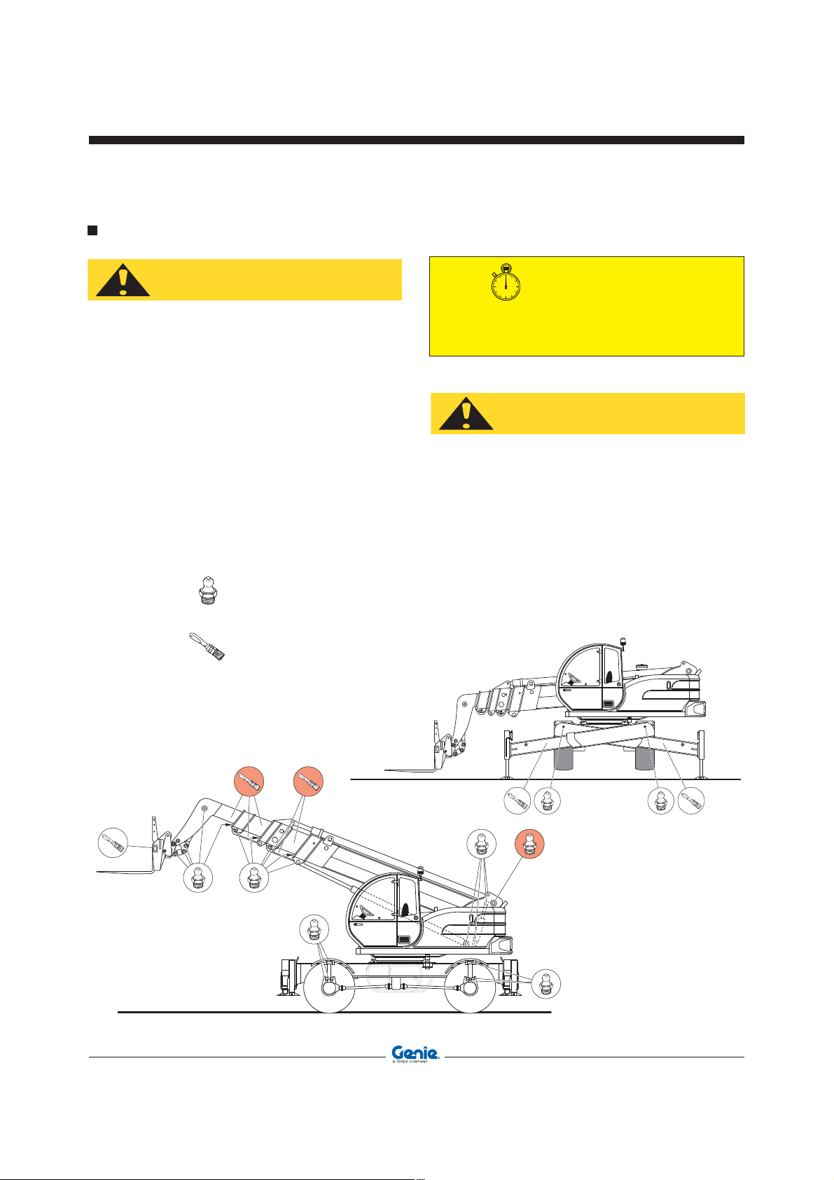
GREASING
Operator’s ManualFirst Edition - Third Printing
Maintenance
CAUTION
Before injecting grease into the greasers,
thoroughly clean them to avoid that mud, dust
or other matters can mix with the lubricant and
reduce or annihilate the lubrication effect.
Remove any old grease with a degreaser from
the telescopes before smearing them with new
grease.
Regularly grease the machine to grant it efficient
conditions and a long life.
By means of a pump, inject grease into the special
greasers.
As the fresh grease comes out, stop the operation.
The greasing points are shown in the following
figures:
- the symbol
greased by a pump
- the symbol represents the points to be
greased by a brush.
represents the points to be
SERVICE INTERVAL
Running-in
Ordinary
__________________________ None
__________________ Every 10 hours
CAUTION
Use only PTFE INTERFLON FIN GREASE LS 2
to lubricate the sliding parts of the telescopic
section. Observe the following schedule:
• After the first 50 operating hours (1 week)
• After the first 250 operating hours (1 month)
• Every 1000 operating hours (6 months)
Remove any old grease from the boom and
smear the sliding area of the blocks with a thin
coat of grease.
Part No. 57.0009.0404 GTH-4518ER - GTH-4020ER - GTH-6025ER 95
Page 96

Operator’s Manual First Edition - Third Printing
Maintenance
TYRES AND WHEELS
On new machines, and when a wheel has been
disassembled or replaced, check the nut torque of
the wheels every 2 hours until they stay correct.
Torque: 400 N/m.
Over-inflated tyres can burst.
Overheated can burst. Do not weld the wheel
rims. For any repair work, call in a qualified
technician.
RIGHT WAY
OKAY
WRONG WAY
WRONG
For the tyre inflation or substitution, please refer to
the table below:
GTH-4518 ER
GTH-6025 ER
GTH-4020 ER
Dimensions
(front and rear)
P.R. (or load
index)
445/65 22.5 18 - 19.5
169 F 16 pr
Rim 14x22.5 14x19.5
Wheel disc 10 holes DIN 70361
Pressure
bar/Psi
8/116 5.5/80
Always use tyres having the dimensions indicated
in the vehicle registration card.
SERVICE INTERVAL
Running-in
Ordinary
_________Within the first 10 hours
_________________ Every 250 hours
BRAKES
For any intervention on the braking system (adjustment
and/or substitution of the brake discs) address to the
TEREXLIFT Technical Assistance Service or the
nearest TEREXLIFT authorised workshop.
96 GTH-4518ER - GTH-4020ER - GTH-6025ER Part No. 57.0009.0404
Page 97

SHAFTING ALIGNMENT
During operation, the alignment of the front and rear
axles of the machine can be subject to variations.
This can depend on an oil blow-by from the steering
control circuit, or on a steering of both axles when
front and rear wheels are not perfectly aligned.
To fix this problem, rather than checking the alignment
visually, follow the procedure below:
1) Move to a solid and level ground
2) Set the steering selection switch 7 to “four-wheel
(pos. 2)
steer”
3) Rotate the steering up to its stop (either to the
right or to the left)
4) Set the steering selection switch to “two-wheel
steer” (pos. 0)
Operator’s ManualFirst Edition - Third Printing
Maintenance
C
105
60
7
5) Rotate the steering up to its stop (turn in the
same direction as above)
6) Reset the steering selection switch to “fourwheel steer" (pos. 2)
7) Rotate the steering (to the side opposite to point
3) so that the rear axle reaches its stop
8) Reset the steering selection switch to “two-wheel
steer" (pos. 0)
9) Rotate the steering (to the same side as in point
7) so that the front axle reaches its stop
10) Reset the steering selection switch to “four-
wheel steer" (pos. 2)
Now the wheels should be re-aligned.
1
0 2
SERVICE INTERVAL
Running-in
Ordinary
__________________________None
__________________ When necessary
Part No. 57.0009.0404 GTH-4518ER - GTH-4020ER - GTH-6025ER 97
Page 98

CAUTION
Operator’s Manual First Edition - Third Printing
Maintenance
ADJUSTING THE SLIDING PADS OF THE BOOM
SECTIONS
Any boom section is fitted with adjustable pads
located on the four sides of the profile. These pads
are secured to both fixed and mobile part of every
section.
All pads can be adjusted by the special shims supplied
by TEREXLIFT upon demand.
Adjusting the pads:
• Remove or loosen the screws fixing the pads in
relation to type of shims used (with or without
slots).
• Fit the necessary amount of shims.
• If the residual thickness of the pad is insufficient
or near the maximum wearing limit, renew the
pad.
• Tighten the screws fixing the pads at the
recommended torque (see below). Use a
dynamometric wrench.
Tightening torques of the pad screws in relation
to the screw diameter
Screws M10 Nm 30
Screws M14 Nm 50
Tightening torques higher than those recommended can cause the break of the pad or of the
locking threaded bush.
Max. wearing thickness
Pads must compulsorily be replaced if the
residual thickness of the plastic layer with
respect to the iron bush fixing the block is equal
or inferior to 1 mm.
SERVICE INTERVAL
Running-in
Ordinary
98 GTH-4518ER - GTH-4020ER - GTH-6025ER Part No. 57.0009.0404
__________________________None
__________________ When necessary
Minimum 1 mm
Page 99

Operator’s ManualFirst Edition - Third Printing
Maintenance
ADJUSTING THE SENSOR DISTANCE
In case of a failure or complete malfunctioning of the
sensors due to a loosening of their fixing ring nuts,
re-adjust their position:
1 Loosen nuts A fixing sensor B.
2 Set the mobile part C of the machine, controlled
by the sensor, as close as possible to it.
Near the sensor to the component until the LED
indicator D lights up.
3 Further near the sensor by 1÷2 mm.
Smoothly tighten the sensor fixing nut and the
relevant lock nut.
The machine is fitted with the following proximity
switches:
E N° 1 turntable unlocking cylinder sensor
F N° 1 turntable rotation locking sensor.
G N° 1 turntable alignment sensor.
1÷2 mm
SERVICE INTERVAL
Running-in _________________________ None
Ordinary _________________ When necessary
Part No. 57.0009.0404 GTH-4518ER - GTH-4020ER - GTH-6025ER 99
Page 100

Operator’s Manual First Edition - Third Printing
Maintenance
TENSIONING THE BOOM CHAINS
To tighten the boom chains, follow the instructions
below:
1. Fully extend the boom
2. Retract the boom by some 20/30 cm.
3. Tighten the chain up to a maximum tension
value of 25 Nm.
4. Check that all chains have been equally
tensioned. If not, repeat the operation described
above
5. Lock the chain tensioners by means of a counternut and locknut.
Running-in
Ordinary
_________________ Every 500 hours
SERVICE INTERVAL
__________________________ None
100 GTH-4518ER - GTH-4020ER - GTH-6025ER Part No. 57.0009.0404
 Loading...