

Page 1
™
GCL-MT
Medium Duty Operator
TROLLEY
111850.501539
08-12
TensiBelt
PROPER APPLICATION
Door Type Operator Type HP/Max Door Weight
Sectional Trolley
(Standard Lift
Low Headroom)
NOT FOR R E S I DENTIAL U S E
This Installation Manual provides the information required to install, troubleshoot and
maintain a GCL-MT
™
Commercial / Industrial Door Operator.
™
1/2HP = 620 lbs
(Available in 1/2HP only)
Page 2

THIS PAGE LEFT BLANK
GCL-MT
Medium Duty Operator
www.geniecompany.com 08-12
Page 3

Table of Contents
Section 1 How to use this manual......................................1.1
Section 2 Safety Information & Instructions...................2.1
Section 3 Critical Installation Information ..............3.1-3.2
Section 4 Installation...............................................................4.1-4.9
Drawbar Assembly................................................4.1-4.6
Attach Operator ....................................................4 7
Connection to the Door .....................................4.8
Clutch and Brake Adjustment ..........................4.9
Section 5 Power and Control Wiring .................................5.1-5.7
Line Voltage Wiring..............................................5.1
Low Voltage Control Wirin
External Wire Diagram ........................................5 3
Wall Control.............................................................5.4
Interlock Switches & Radio Control................5 5
Radio Control & Photocell Wiring ...................5.6
Sensing Edge Wiring............................................5 7
Section 6 Operator Setup Procedures ..............................6.1-6.8
Control Panel..........................................................6.1
Setting Constant Contact ..................................6 2
Setting Limit Travel...............................................6.3
Setting Limit Overrun..........................................6.4
Monitored Reversing Devices.....................
Max Run Timer .......................................................6.6
Setting the Mid-Stop ...........................................6 7
Changing Open & Close Modes ......................6.8
g ..............................5.2
......6.5
Section 7 Special Operator Features .................................7.1-7.2
Operator Cycle Count..........................................7.1
Circuit Board Firmware version .......................7.1
Operator Type ........................................................7.2
Section 8 Troubleshooting....................................................8.1-8.4
Section 9 Service & Maintenance .......................................9.1
Section 10 Appendix A .............................................................10.1-10.9
Section 11 Warranty...................................................................11.1
Display Operation.................................................8.1
Error Codes..............................................................8.1-8.2
Run Codes................................................................8.2-8.3
LED Indicators ........................................................8.4
Safe-T-Beam® Monitored Photocell
Troubleshooting Chart .......................................8.5
Basic Operator Parts........................................10.1
Basic Shaft Assembly Parts............................10.2
Basic Rail/Trolley Pa r ts.................................10.3
Basic Electric Box
Appendix B..............................................................10.5
Screw Terminal Assignments.......................10.5
Appendix C..............................................................10.6-10.8
Display Run Codes...........................................10.6
Display Er
Parts...................................10.4
ror Codes .........................................10.7-10.8
GCL-MT
Medium Duty Operator
TOC
www.geniecompany.com 08-12
Page 4
Section 1: How to use this manual
The 11 sections of this Installation Manual provide the information required to install,
troubleshoot and maintain an GCL-MT™ commercial/industrial door operator.
Section 2
Provides important defining information related to safety terminology used throughout this manual, as
well as safety related instructions which must be followed at all times while doing any
steps/tasks/instructions detailed in this manual.
Section 3
Details pre-installation concerns/issues/decisions that are recommended to be considered and/or
esolved prior to beginning any commercial door operator installation.
r
WARNING
Failure to correctly perform all steps in sections 4-6 can result in serious injury or death.
Sections 4-6
Provide step by step installation and set-up instructions for the GCL-MT™ commercial door operator. Each
section is written such that it must be followed in a step by step order to complete a successful
installation.
Sections 7-8
Detail important features and troubleshooting information for typical installation and normal operations
tha
Sections 9-11
Pr
troubleshooting and service activities, along with important warranty and returned goods policy
information.
FOR ASSISTANCE CALL 1-800-843-4084
occur.
t may
ovide related information on service and maintenance items, operator drawings for use in
GCL-MT
Medium Duty Operator
www.geniecompany.com 08-12
1.1
Page 5
Section 2: Safety Information & Instructions
Commercial/Industrial Sectional and Rolling Steel Doors are large, heavy objects that move with the help of springs under high tension
and electric motors. Since moving objects, springs under tension, and electric motors can cause injuries, your safety and the safety
of others depend on you reading the information in this manual. If you have any questions or do not understand the information
presented, call your nearest service representative. For the number of your local Genie® Dealer, call 800-OK-GENIE, and for Genie®
Factory Technical Advice, call 800-843-4084.
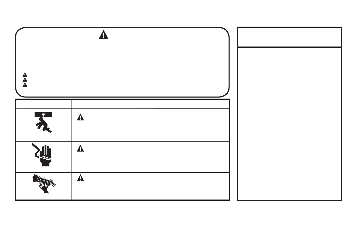
In this Manual, the words Danger, Warning, and Caution are used to stress important safety information. The word:
DANGER indicates an imminently hazardous situation which, if not avoided, will result in death or serious injury.
WARNING indicates a potentially hazardous situation which, if not avoided, could result in death or serious injury.
CAUTION indicates a potentially hazardous situation which, if not avoided, may result in injury or property damage.
The word NOTE is used to indicate important steps to be followed or important considerations.
POTENTIAL HAZARD EFFECT PREVENTION
WARNING
Could result in
Serious Injury
MOVING DOOR
ELECTRICAL SHOCK
HIGH SPRING TENSION
or Death
WARNING
Could result in
Serious Injury
or Death
WARNING
Could result in
Serious Injury
or Death
WARNING
Do Not operate unless the doorway is in sight and free of
obstructions. Keep people clear of opening while door is moving.
Do Not allow children to play with the door operator.
Do Not change operator control to momentary contact unless an
external reversing means is installed.
Do Not operate a door that jams or one that has a broken spring
Turn off electrical power before removing operator cover.
When replacing the cover, make sure wires are not pinched or near
moving parts.
Operator must be electrically grounded.
Do Not try to remove, repair or adjust springs or anything to which
door spring parts are fastened, such as, wood block, steel bracket,
cable or any other structure or like item.
Repairs and adjustments must be made by a trained service
.snoitcurtsni dna sloot reporp gnisu evitatneserper
IMPORTANT
READ PRIOR TO ANY DOOR OPERATION
1. Read manual and warnings carefully.
2. Keep the door in good working condition.
Periodically lubricate all moving parts of
door.
3. If door has a sensing edge, check
operations monthly. Make any necessary
repairs to keep it functional.
4. AT LEAST twice a year, manually operate
door.
The Door should open and close freely. If it
does not, the door must be taken out of
service and a trained service representative
must correct
the malfunction.
5. The Operator Motor is protected against
overheating by an internal thermal protector.
If the operator ceases to function because
motor protector has tripped, a trained service
technician may need to correct the condition
which caused the overheating. When motor
has cooled, thermal protector will
automatically reset and normal operation can
be resumed.
6. In case of power failure
operated manually by pulling the release
cable to disconnect the operator drive system.
7. Keep instructions in a prominent location
near the pushbutton.
the condition causing
, the door can be
GCL-MT
Medium Duty Operator
www.geniecompany.com 08-12
2.1
Page 6
Section 3: Critical Installation Information
Job Site Issues to Consider/Concerns
The following list of items should be considered prior to selecting an operator for a given job site.
1-Available power supply.
2-Type of door.
3-Potential operator mounting obstructions. Items to consider include, but are not limited to: side room, room above door shaft,
surface integrity, power supply location, and convenient chain hoist and release cable positioning.
4-Size of door for appropriate
6-Door activation needs/requirements. Examples include 3 button control stations, 1 button control stations, radio controls, pull
key switches, etc. See “Entrapment Protection” section below.
7-Interlock switches are required under certain conditions for doors with pass doors and door locks. See page 5.5.
8-Accessory equipment. Examples are reversing edges and/or photocell beams (required for
ENTRAPMENT PROTECTION
The installation of a fail safe external reversing device (such as a monitored reversing edge or photocell system, etc.) is required on all momentary contact electronically
operated commercial doors. If such a reversing device is not installed, the operator will revert to a constant contact control switch for operation (Closing only).
The Reversing Devices currently UL Approved with are:
1)
MillerEdge ME, MT and series monitored edge sensors used in combination with Timer-Close Module P/N OPABTCX.S or OPAKMEIGX.S INTERFACE MODULE.
2) Residential Safe-T-Beam® Monitored Photocells from The Genie® Company, model OSTB-BX (P/N 38176R).
2) Series II Commercial Safe-T-Beam®, Monitored Photocells P/N OPAKPE.S.
3) Series II Commercial Safe-T-Beam®, Monitored Photocells P/N OPAKPEN4GX.S.
operator torque and door travel speed selection.
and corrosiveness of the location.
dustiness 5-Operator mounting environment. Items to consider include operator location and dampness,
doors set to operate as momentary contact,), auxiliary control relays, warning lights, etc.
room below door shaft, available mounting
cords, loop detectors, photoelectric controls,
GCL-MT
WARNING:
CAUTION:
Check working condition of door before installing the operator. Door must be free from sticking and binding. If equipped, deactivate
any door locking device(s). Door repairs and adjustments, including cables and spring assemblies MUST be made by a trained service
representative using proper tools and instructions.
Medium Duty Operator
DO NOT apply line voltage until instructed to do so.
www.geniecompany.com 08-12
3.1
Page 7
Section 3: Critical Installation Information
ENTRAPMENT PROTECTION
The GCL-MT™ can be used with the following UL Listed entrapment devices in compliance with UL325 requirements active starting August 29, 2010.
UNTIL ONE OF THESE MONITORED EXTERNAL ENTRAPMENT DEVICES IS INSTALLED, THE
MillerEdge ME, MT and CPT series monitored edge sensors used in combination with
Timer-Close Module or OPAKMEIGX.S Interface Module.
Residential Safe-T-Beam® Monitored Photocells model OSTB-BX P/N 38176R.
Commercial Monitored Photoeye Kit P/N OPAKPE.S
Commercial NEMA4 Monitored Photocells P/N OPAKPEN4GX.S.
Sectional Door Chart (sq. ft.)
Door S er ies ->
UL L is tedHPMod el
GCL-MT 1/2
T=Trolley
Note: Total door weight, and not the square footage, is the critical factor in selecting the proper operator.
Square footage measurements are based on "square doors." (Example=16' x 16')
NOTE: Doors that require special windloading and wide doors, normally require increased strutting (reinforcement). Strutting doors can significantly increase door
weight beyond weight shown. Consult Customer Service for the impact of wind load andstrutting on square foot limits.
NOTE: "PU-FIP" stands for "polyurethane, foamed-in-place." If no notation is present, insulation is "polystyrene, layed-iin-place."
Ye s TS 620 170 120 230 160 270 200 300 256 256 256 240 160 256 256 210 144
Mounting
Type
216 216 ins. 220 220 ins. 2415 2415 ins. 2411 2411 ins. 125 150 200 200-20 5150 5200 451 452
Max.
16GA.
Door
Flush
Weight
Steel
(Lbs)
CommercialSteelInsulated&Non-Insulated Thermospan Thermomark
16GA.
Flush
Steel
Insulated
20GA.
Ribbed
Steel
20GA.
Ribbed
Insulated
Steel
OPERATOR
24GA.
Ribbed
Steel
WILL NOT ALLOW MOMENTARY CONTACT OPERATION IN THE CLOSE DIRECTION.
HTDIW ROOD ELBAWOLLA SECIVED DETSIL
ANY WIDTH
30 FEET
30 FEET
35 FEET
Aluminum
PU/FIP
PU/FIP
24GA.
Ribbed
Steel
Insulated
Nominal
24GA.
Ribbed
Steel
Nominal
24GA.
Ribbed Steel
Insulated
PU/FIP
Insulated
PU/FIP
Insulated
1.38"
PU/FIP
Insulated
2"
PU/FIP
Insulated
2"
20GA.
Exterior
Insulated 1/4" or 1/2"
Insulated
Raised
Raised
Panel
Panel
2"
1.38"
1/8" Glass
1.38"
Glass
1.38"
GCL-MT
Medium Duty Operator
www.geniecompany.com 08-12
3.2
Page 8
Section 4: Installation
IMPORTANT
INSTALLATION INSTRUCTIONS
To reduce the risk of severe injury or death:
WARNING
1) READ AND FOLLOW ALL INSTALLATION INSTRUCTIONS.
2) Install only on a properly operating and balanced door. A door that is operating
improperly could cause severe injury. Have qualified service personnel make
repairs to cables, spring assemblies and other hardware before installing the operator.
3) Remove all pull ropes and remove, or make inoperative, all locks (unless mechanically
and/or electronically interlocked to t
before installing the operator.
4) Install the door operator at least 8 feet above the floor if the operator has exposed
moving parts.
5) Do not connect the door operator to the power source until instructed to do so.
6) Locate the control station: (a) within sight of the door, (b) a minimum of 5 feet above
the floor so that small children c
of the door.
7) Install the Entrapment Warning Placard next to the control station
prominent location.
8) For products having a manual release, instruct the end user on the operation of the
manual release.
-
Figure 1
he power unit) that are connected to t
annot reach it, and (c) away from all moving parts
he door
and in a
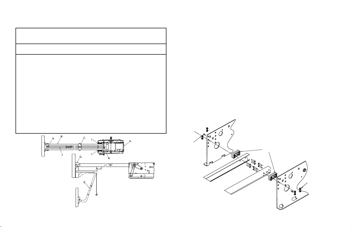
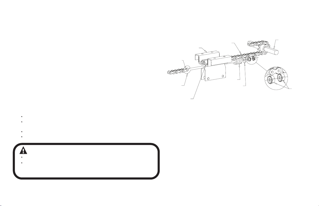
Drawbar Assembly
The Model GCL-MT™ Drawbar Operator consists of the Power Unit (A),
Drawbar Track (B), Chain Guides (C), Drawbar Arm (E), Front Spreader (G),
Front Idler Pulley (H), Drive Chain (J), Drive Sprocket (K) and Drawbar
Track Spacer (L). The Drawbar track length, chain length and quantity of
chain guides will vary by door heights. Fig.1.
1) The Drawbar Track Spacers are attached to the Power
Unit at the factory. Fig. 1.
– Attach Track to Power Unit at the Spacers using eight
(8) 1/4"-20 x 1-1/2" track bolts and 1/4"-20 keps nuts (provided).
Fig. 2. The curved part of the Track MUST be toward the
electrical panel.
NOTE: Drawbar tracks must be thirty (30) inches longer than the door’s
height. Tracks have been pre-punched at the door plant for the chain
guide assemblies.
Figure 2
1/4"-20
KEPS NUTS
Track Spacers are factory installed.
1/4"-20
KEPS NUTS
GCL-MT
Medium Duty Operator
www.geniecompany.com 08-12
4.1
Page 9
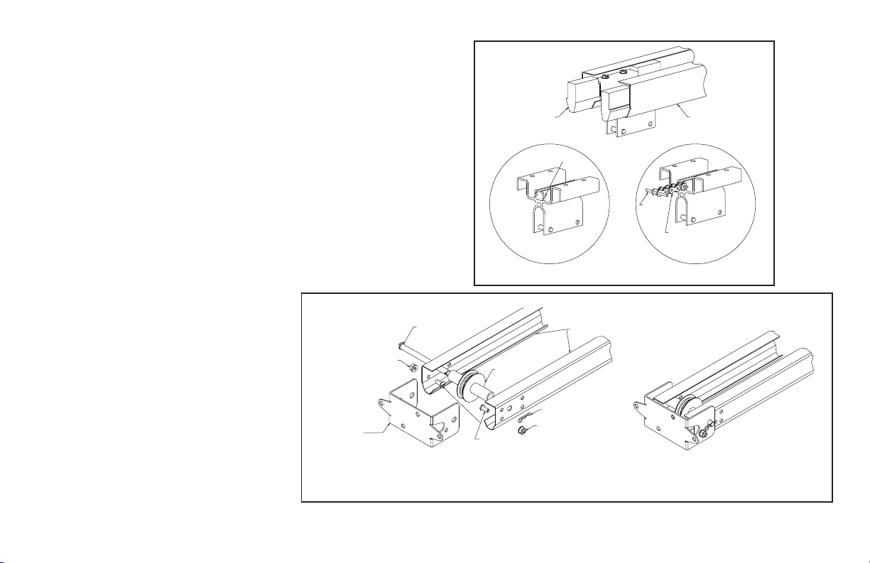
Drawbar Assembly (cont’)
3) Insert the carriage into the tracks as shown in Fig. 3.
NOTE: One end of the carriage has a notch (Detail A) which will be
used to locate the chain pin (Detail B). This end of the carriage faces
the front spreader bracket and away from the power unit.
4) Attach the front spreader bracket to the front of the operator
tracks with two (2) track bolts and two (2) locknuts (check hole
alignment before installing).
5) Position the idler pulley inside the track and insert the
3/8" x 4-1/2" clevis pin. Secure the clevis pin using the
hitch pin. Fig. 4.
NOTE:Track bolts MUST be installed
from inside the track.
CARRIAGE
DETAIL A
NOTCH
Figure 3
CHAIN
PIN
TRACK
CHAIN
DETAIL B
GCL-MT
Medium Duty Operator
FRONT
SPREADER
BRACKET
LOCK NUT
CLEVIS PIN
IDLER PULLEY
TRACK
BOLTS
EXPLODED VIEW ASSEMBLED VIEW
HITCH PIN
LOCK
NUT
TRACK
Figure 4
www.geniecompany.com 08-12
2
4.
Page 10
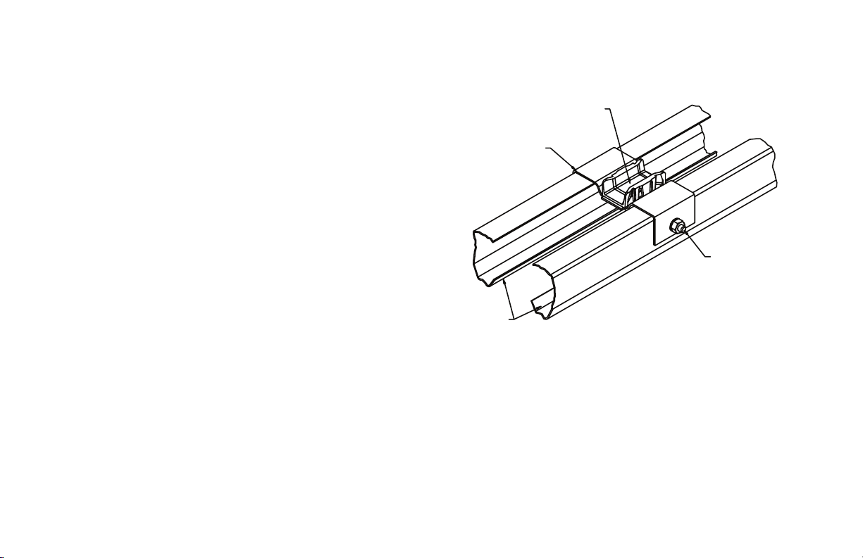
Drawbar Assembly (cont’)
6) Attach the chain guide assemblies to the drawbar tracks
using track bolts and locknuts. Fig. 5.
NOTE: Space chain guides evenly between operator and header. Doors
12 foot tall and under will use 2 chain guides. Doors over 12 feet will
require 3 chain guides.
CHAIN GUIDE
BRACKET
PLASTIC SLIDE
GUIDE
NOTE:Verify that track bolts are properly seated in track. Failure to seat
bolts can cause carriage to bind in door track.
GCL-MT
Medium Duty Operator
www.geniecompany.com 08-12
TRACK
Figure 5
SLOTS ARE PROVIDED
TO ATTACH BRACKET
USING TRACK BOLT
WITH LOCK NUT
(BOTH SIDES)
ALTERNATELY: A 9/32 HOLE
CAN BE DRILLED IN
THE TRACK. THE HOLES
WILL NEED TO BE
DEBURRED BEFORE
INSERTING TRACK BOLTS
4.3
Page 11
Drawbar Assembly (cont’)
7) Uncoil the drawbar chain and install by routing the chain over
the chain guides and around the drive sprocket on the output
shaft as shown in Fig. 6
.
8) Pass the chain through the rectangular slot in the carriage and
insert the chain pin through the end link of the chain.
9) Pass the other end of the chain between the front spreader
bracket and the idler pulley. Make certain the chain is
not twisted.
10) Move chain toward the carriage.
11) Attach the eye bolt to the chain using the #41 master chain link.
12) Attach the chain to the carriage.
13) Insert the eye bolt through the hole in the carriage.
14) Place the spring and flat washer
over the eyebolt.
15) Thread a single nut onto the eyebolt as shown in Detail A, Fig 6
16) Tighten Chain with no more than 2" of sag and add second
locknut. Detail A, Fig 6.
Check to ensure the following:
The chain is properly engaging the output sprocket.
The chain pin is properly seated in the indentations on the
front of the carriage.
The chain is properly seated on the rib of the idler pulley.
The chain is not twisted.
WARNING
DO NOT apply line voltage until instructed to do so.
Repairs and adjustments, including particularly to cables and
spring assemblies under high tension, must be made by a trained
service representative using proper tools and instructions.
.
MASTER LINK
EYEBOLT
CHAIN PIN
CARRIAGE
CHAIN
SPRING
WASHER
Figure 6
TROLLEY
SPROCKET
& SHAFT
DETAIL A
LOCK
NUT
GCL-MT
Medium Duty Operator
www.geniecompany.com 08-12
4.4
Page 12
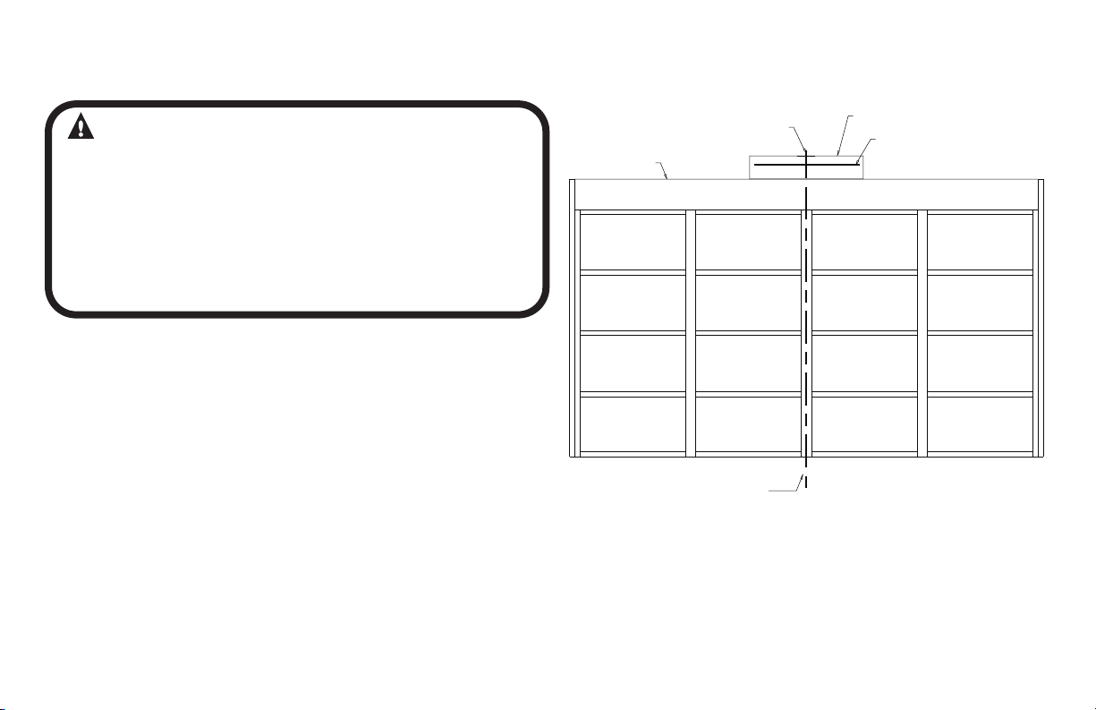
Drawbar Installation
CAUTION
Check the working condition of the door before installing the
operator.Door must be free from sticking and binding.
If the door is equipped with a latching device, secure the locking
bar in the open (unlocked) position. This style operator will act as a
latching device when the door is down and therefor the door’s
lock is no longer needed.
If the door lock is to remain functional, an interlock switch MUST
be installed which will prevent operation of the door whenever
the door lock is engaged. Refer to the Wiring Instructions, section
5.5, of this manual for proper connection of the interlock switch.
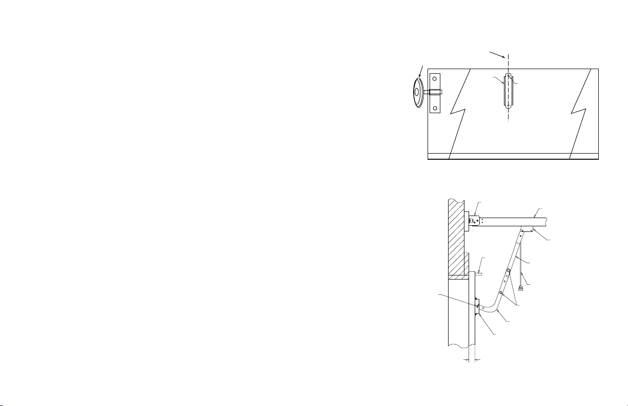
1) Measure the
vertical line as shown in Fig. 7.(If the vertical line is not in line
with a door stile, a means of attaching the door bracket to the
door must be provided. This can be accomplished by spanning
the center of the door’s top section (between the top and
bottom rail) with a suitable material such as wood or steel.
NOTE: On torsion spring doors with an uneven number of panels, the
operator may be attached to the stile nearest to the center.
2) Prepare for attaching drawbar to header. If suitable woodwork is
not already in place, securely affix a 2" x 6" block of wood as
shown in Fig. 7.
3) Center the block on the header.
4) Mark the center ve
5)
Use a level, as shown in Fig
of travel for the door.
6) Mark a horizontal line across the vertical line you made on
the header at 2-1/2" above the highest point of door travel.
width of the door to determine the center. Make a
rtical line on this block.
. 8 (pg 4.6) to find the highest point
HEADER
VERTICAL LINE
(SEE STEP 1)
CENTERLINE
OF DOOR
Figure 7
2" X 6" (SEE STEP 2)
HORIZONTAL LINE
(SEE STEP 6)
GCL-MT
Medium Duty Operator
www.geniecompany.com 08-12
4.5
Page 13
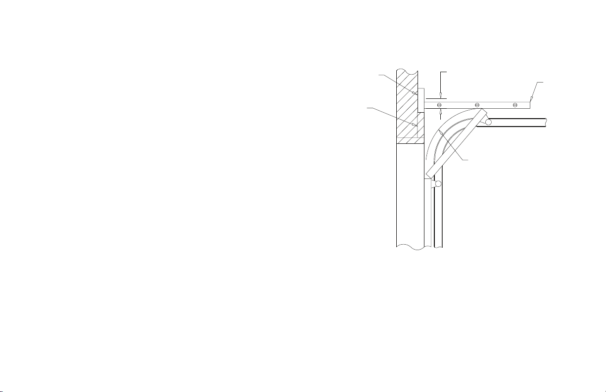
Drawbar Installation (cont’)
1) Raise the operator into a position approximately 4" above the
horizontal door tracks.
2) Temporarily suspend the operator from the ceiling
superstructure with rope or by some other safe and
suitable means.
3) Position the bottom edge of the front spreader bracket on
your horizontal mark on the header. Fig. 8.
2" X 6"
HEADER
MAKE MARK 2-1/2"
ABOVE HIGH ARC OF
DOOR FOR HORIZONTAL
LINE
HIGH ARC
OF DOOR
Figure 8
LEVEL
GCL-MT
Medium Duty Operator
www.geniecompany.com 08-12
4.6
Page 14
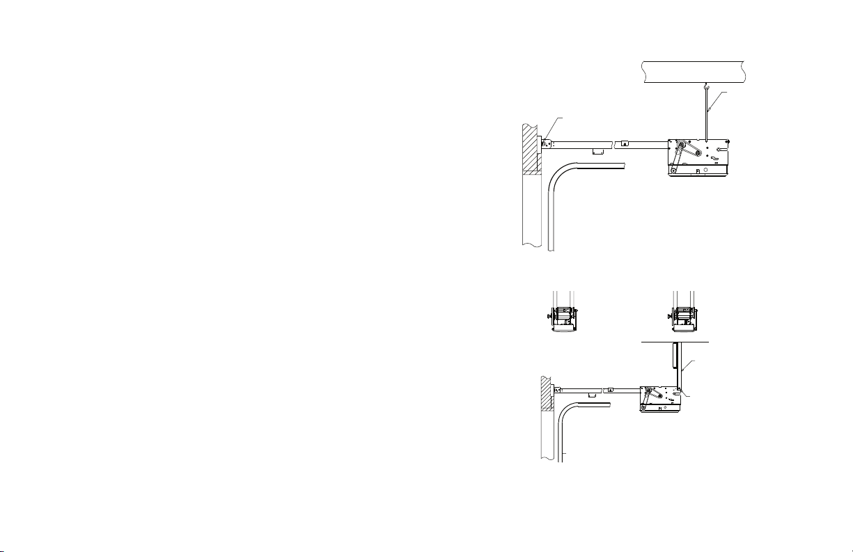
Attach Operator.
4) Center spreader bracket on the vertical line. Use two (2)
1/4" x 1-3/4" lag bolts to attach the bracket to the header. Fig. 9.
5) Raise the door and position the operator so that the
drawbar tracks are level and the operator chain is in line
with the center of the door (or the stile where the door bracket
will be attached). Fig. 9.
6) Secure the operator in this position by installing steel angles
(not furnished) between the ceiling superstructure and the
operator power unit. Fig. 10.
1/4" X 1-3/4" LAG BOLTS
STEEL
ANGLES
(NOT INCLUDED)
07-11
Figure 10
Figure 9
ROPE OR CABLE
STEEL ANGLES
(NOT INCLUDED)
DRILL HOLE IN ANGLE
AND MOUNT USING
REAR SUPPORT
CARRIAGE BOLT
GCL-MT
Medium Duty Operator
www.geniecompany.com 08-12
4.7
Page 15
Connection to the Door
1) Pull down on the drawbar arm locking sleeve and attach to
carriage.
2) Position the door bracket on the door as shown in Fig. 11,
with mounting holes on the door centerline. (Even with or
above top door roller).
3) Fasten the door bracket to the door using two
1/4" -20 X 2-1/4" carriage bolts and nuts for wood doors.
Use 1/4"- 20 self tapping sheet metal screws for metal doors.
Or as recommended by the door manufacturer.
4) Use two (2) 3/8" -16 X 7/8" bolts and nuts to attach the
door curved door arm to the straight drawbar arm.
NOTE: Use the set of holes that align the drawbar in a near vertical
position for operators without a brake
rearward angle for operators with a brake.
For units without a brake, set arms as close to 0 degrees as possible.
Fig.12.
NOTE: If the door strut interferes with the mounting of the door
bracket, position the door bracket below the strut. DO NOT,in any way,
cut or modify the strut.
GCL-MT
Medium Duty Operator
. Set arms at a 20-30 degree
www.geniecompany.com 08-12
Figure 11
CLEVIS/COTTER
PIN
Figure 12
Top Door Roller
Door Center Line
DOOR
BRACKET
FRONT SPREADER
BRACKET
STRUT
1 -5/8" (REF.)
ATTACH TO DOOR WITH
1/4" -20 X 2 -1/4"
CARRIAGE BOLTS
W/NUTS
(OR AS RECOMMENDED
BY DOOR
MANUFACTURER)
DRAWBAR ARM (STRAIGHT)
RELEASE CORD
3/8"-16 X 7/8" HEX HEAD BOLTS
WITH 3/8" - 16 FLANGE NUTS
DRAWBAR ARM (CURVED)
DOOR BRACKET
TRACK
CARRIAGE
4.8
Page 16
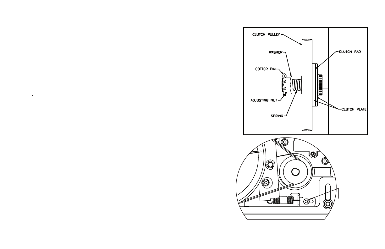
Clutch Adjustment
These operators have a friction style clutch that can be adjusted.
NOTE:The clutch is intended to provide protection for the door, the operator and
associated equipment. It is not intended for entrapment protection. They
have a motor reversing feature that is integrated with the clutch assembly. If an
obstruction is placed in the pathway of the door during operation the motor will
stop and reverse when the clutch begins to slip. Therefore, the adjustment of the clutch
should be such that the door and operator function in this manner. The clutch should be
such that the door and operator function in this steps for clutch adjustment follow:
To Adjust the Clutch
1) Decrease the tension on the clutch until the operator will not lift the door.
Turn the adjusting castle nut counter-clockwise to decrease clutch tension and
clockwise to increase clutch tension.
2) After completing step 1, begin to increase tension on the clutch until the operator
is capable of lifting the door through the complete cycle without clutch slippage.
3) Test the reversing feature of the operator by placing an obstruction under the
door during a close cycle. The door should reverse on the obstruction and return
to the open position. If the door does not close but comes down part way and
reverses without any obstructions in its path, then increase the clutch tension
until the door will close fully.
4) Finally, insert the cotter pin through the castle nut and shaft and bend the
outer leg of the cotter pin.
NOTE: Periodically check the system for proper clutch a
starts to slip after w
operation of door BEFORE adjusting clutch. The door ma
operating freely or the counterbalance spring may need adjusting.
Repairs and adjustments must be performed by a trained service
representative using proper tools and instructions.
orking properly for some time, check manual
ction. If clutch
y not be
To Adjust the Brake
1) Loosen the Adjustment Bracket Lock Nut/Bolt.
2) Slide the Adjustment Bracket as needed to reach the desired spring tension.
When properly adjusted, the pivot arm should move with very little effort.
3) Re-tighten the Adjustment Bracket Lock Nut/Bolt.
GCL-MT
Medium Duty Operator
www.geniecompany.com 08-12
Figure 13
41 erugiF
LOCK NUT & BOLT for
BRAKE ADJUSTMENT
4.9
Page 17

Section 5: Wiring
Line Voltage Wiring
Fig. 1
WARNING
DO NOT apply power to operator until instructed to do so.
The Genie® Company recommends that line voltage
wiring be performed by a qualified electrician.
Be sure that electrical power has been disconnected from
the input power wires being connected to the operator
prior to handling these wires. An appropriate lock-out /
tag-out procedure is recommended.
Line voltage wiring must meet all local building codes.
Make sure operator voltage, phase and frequency
nameplate ratings are identical to the job site line
voltage ratings.
Input power wiring must be properly sized for the
operators amperage rating located on the nameplate.
To redu
of this unit is properly grounded.
1) Remove LINE VOLTAGE INPUT PLUG and install proper
fittings and 1/2"conduit.
2) Route proper LINE VOLTAGE wires into operator.
3) Locate LINE INPUT terminals on circuit board. Using
correct connectors, attach wires to LINE INPUTS, and GROUND
terminal. Fig. 2.
Keep low voltage and line voltage wires separate.
Route all line voltage wires as shown.
Plug all unused conduit holes.
ce the risk of electric shock, make sure the chassis
Figure 1
ROUTE LOW VOLTAGE
WIRING IN SHADED
AREA AS SHOWN
Figure 2
LINE INPUT
TERMINALS
LINE IN
POWER CONNECTIONS
L1 L1
LINE
120V
(HOT)
240V
LINE 1
LINE
GROUND
HIGH VOLTA GE
INPUT PLUGS
N L2
NEUTRAL
LINE 2
GND
GCL-MT
Medium Duty Operator
www.geniecompany.com 08-12
5.1
Page 18

Low Voltage Control Wiring (general) Fig.3
1) Connect all LOW VOLTAGE control circuit wires to this side
of unit using 1/2" conduit or flexible convoluted tubing.
Keep low voltage and line voltage wires separate.
Route all low voltage control wiring as shown. This includes
all control circuit wires such as wall controls, timers and single
button input devices as well as radio control and safety circuit
wiring. See Figs 4 through 13 in this section.
Plug all unused conduit holes.
NOTE: For a detailed description of control wire terminals see
Appendix B.
RADIO
CONTROL
TERMINALS
LOW VOLTAGE
CONTROL WIRE
TERMINALS
LOW
VOLTAGE
INPUT
PLUGS
ROUTE LOW VOLTAGE
WIRING IN SHADED
AREA AS SHOWN
Figure 3
GCL-MT
Medium Duty Operator
www.geniecompany.com 08-12
5.2
Page 19

LINE IN
POWER CONNECTIONS
L1/ L1
LINE
120V
(HOT)
240V
LINE 1
N/ L2
NEUTRAL
LINE 2
GND
OPEN
CLOSE
STOP
OPEN CLOSE
MULT PLE 3-BUTTON
STATION INSTALLATIONS
REQUIRE THE STOP
BUTTON TO BE WIRED
IN SER ES. See Fig. 5, pg 5.4
External Wire Diagram
See Appendix B for detailed description of terminals.
CONTROL SIGNAL TERMINAL STRIP
STOP GND 1-BTN
REMOVE JUMPER
IF STOP BUTTON
IS USED
CLASS 2 SUPPLY 0-40 VDC
ODC
STB
1-BTN
STATION
N/O
KEY
SWITCH
STATION
N/O
CARD
READER
N/O
O/C
PULL
SWITCH
N/O
ODC
STB
N-O
SAFETY
N-O
EXT
SAFETY
INTLK
REMOVE JUMPER
WHEN INSTALLING
EXTERNAL INTERLOCK
SENSING EDGE SWITCH
(DO NOT CONNECT 2-WIRE
MONITORED SENSING EDGE
SWITCH TO THESE ,INPUTS)
EXT
INTLK
PWR
20-40 VDC @ 315mA
MAX CURRENT
EXTERNAL RADIO TERMINAL STRIP
CLASS 2 SUPPLY 0-40 VDC
PWR
NOM
+ 24VDC
+
RAD GND
RELAY
GND
RADIO
+
-
-
GCL-MT
3-BUTTON
STATION
Medium Duty Operator
®
SERIES II SAFE-T-BEAM
(CONNECT STB WIRES TO EITHER TERMINAL)
(STB)
www.geniecompany.com 08-12
(OPAKMEIGX.S)
MONITORED SENSING EDGEINTERFACE MODULE
THRU-BEAM
PHOTOCELLS
5.3
Page 20

Wall Control
1) For a single 3 - button installation, make connections as
shown in Fig. 4.
2) For a multiple 3 - button installations, make connections as
shown in Fig. 5.
For single button accessory controls, make connections as
3)
shown in Fig. 6.
NOTE: If an External STOP button is NOT being installed, a jumper
wire must b
as shown in Fig. 6.
NOTE: Long Distance Relay K
distanc
Wall Control(s) must be located so that the door is within
sight of the user and far enough from the door, or positioned,
such that the user is prevented from coming in contact with
the door while operating the controls.
Attach the Warning placard adjacent to the Wall
Control. Fig. 4A
Attach the Caution label adjacent to the Wall Con Fig. 4B.
GCL-MT
e installed between the "ST
it wiring is not required for long
e control runs and should not be used
WARNING:
.
OPEN CLOSE
Medium Duty Operator
CONTROL SIGNAL TERMINAL STRIP
STOP GND -BTN
OPEN
CLOSE
STOP
3-BUTTON
STATION
ODC
STB
NOTE:
JUMPER BETWEEN STOP
AND GND TERM NALS
MUST BE REMOVED
Figure 4
ODC
STB
OP" AND "GND" terminals
trol.
N-O
N-O
SAFETY
SAFETY
EXT
EXT
INTLK
INTLK
Figure 4A
Entrapment
Warning
Placard
www.geniecompany.com 08-12
WARNING:
OPEN CLOSE
3-BUTTON
STATION
3-BUTTON
STATION
Figure 5
CONTROL SIGNAL TERMINAL STRIP
STOP GND -BTN
OPEN
CLOSE
STOP
OPEN
CLOSE
STOP
ODC
STB
NOTE:
JUMPER BETWEEN STOP
AND GND TERMINALS
MUST BE REMOVED
OPEN CLOSE
NOTE:
JUMPER BETWEEN
STOP AND GND
TERMINALS
MUST BE INSTALLED.
Figure 6
STOP GND -BTN
If momentary contact control is to be used, a monitored
N O
N-O
ODC
STB
EXT
SAFETY
SAFETY
INTLK
CONTROL SIGNAL TERMINAL STRIP
ODC
STB
1-BTN
STATION
KEY
SWITCH
STATION
CARD
READER
OPEN/CLOSE
PULL
SWITCH
EXT
INTLK
N-O
N-O
ODC
SAFETY
STB
SAFETY
EXT
EXT
INTLK
INTLK
external reversing device such as a photocell system or sensing edge
switch must be used. See pages 5.6-5.7 for installation of entrapment
protection devices.
Figure 4B
Thi s do or i s ope rate d by a li mite d-dut y op erat or.
To p reven t th e mo tor p rote ctor from tri ppin g,
CAUTION
do not excee d 15 cyc les of op enin g
and clo sing per hour.
NOT FOR RESIDENTIAL USE
11 35
5.4
Page 21

Interlock Switches
1) Optional external interlock switches are required on some Sectional or Rolling Steel
Doors to prevent door from operating under certain conditions including the following:
If the door is equipped with a functioning door lock, an interlock switch must be
installed to prevent electric operation when the lock is engaged.
If the door is equipped with a pedestrian pass-through door, an interlock switch must
be installed at the pass-through door in order to prevent electrical operation when
the pass-through door is open.
Pass door interlock:
Should be open when
door is open.
Closed when door is
closed.
OPEN CLOSE
SWITCH
(N.O.)
CONTROL SIGNAL TERMINAL STRIP
STOP GND 1 BTN
ODC
ODC
STB
STB
N O
SAFETY
N O
SAFETY
EXT
INTLK
EXT
INTLK
NOTE: If External Interlock is used,THE JUMPER WIRE BETWEEN THE
EXT INTLK TERMINALS MUST BE REMOVED.
Side lock interlock:
Should be open when
door is locked.
Closed when door is
unlocked.
GCL-MT
Medium Duty Operator
www.geniecompany.com 08-12
Switches must be
set in the field.
Figure 7
ANGLE
STANDARD
SLIDELOCK
SWITCH
(N.C.)
TRACK
5.5
Page 22

Radio Control and Photocell Wiring
Radio Control Installation
in Fig. 8.
NOTE: PWR terminal supplies 20 – 40VDC. Radios used must be
compatible with this voltage range.
NOTE: If no voltage is present at PWR terminal, check fuse F1 on control board.
Series II Safe-T-Beam® Monitored Photocells
1) Monitored SERIES II (STB) photocells (P/N
Safe-T-Beam® Monitored Photocells from Genie® (P/N 38176R).
Wiring to these photocells can be connected to either terminal (they are
OPAKPE.S or OPAKPEN4GX.S) and
not polarity sensitive). ( Troubleshooting in Section 8).
NOTE: Monitored Sensing device must be installed or unit will be Constant Contact Close.
WARNING
Actuating operator using constant contact on
:
the CLOSE button will override external reversing devices, including photocells.
2) To Mount Photocells: (Kit includes detailed Instructions).
Determine location for mounting. They do not need to be directly adjacent to the door but
Screws provided for mounting on soft material (wood, drywall, etc.).
away from the wall sufficiently that no door hardware
breaks the plane of the photo-beam.
nwohs sa snoitcennoc ekam,noitallatsni lortnoc oidar eriw-3 a roF)1
Fig. 9.
.meht neewteb enil detcurtsbonu na si ereht os llaw eht no eb tsum
Fig 10.
They must extend out
igure 8
F
EXTERNAL RADIO TERMINAL STRIP
CLASS 2 SUPPLY 0-40 VDC
LOCATED
OUTSIDE
ELECTRIC
BOX
RELAY
NOM
+24VDC
RADIO
PWR
20-40 VDC @ 315 mA
MAX CURRENT
RAD GND
PWR
GND
DOOR
01 erugiF
Figure 9
CONNECT WIRES TO EITHER TERMINAL.
(NOT POLARITY SENSITIVE
SERIES RESIDENTIAL
SAFE-T-BEAMS (STB)
Top of lens
to floor.
)
CONTROL SIGNAL
TERMINAL STRIP
ODC
STB
ODC
STB
WARNING
Photocell systems provide entrapment protection
:
when mounted near the doorway in such a way that the lower portion of an individual’s
leg will break the photocell beam during normal walking conditions.
Commercial Non-Monitored Photocells
1) Nominal 24 Volt DC Commercial photocells with normally open contacts can be
connected as shown in Fig. 11.
NOTE:
Blue wire supplies 20 – 40VDC. Photocells used must be compatible with this voltage range.
NOTE If no voltage is present at Blue wire, check fuse F-1 on Control board.
GCL-MT
Medium Duty Operator
www.geniecompany.com 0 -12
CONTROL SIGNAL
TERMINAL STRIP
N-O
N-O
REVERSE
REVERSE
RECEIVER
+
-
THRU-BEAM
PHOTOCELLS
PWR
20 0 VDC @ 3 5 mA
MAX CURREN
EXT RADIO CONNECTOR
Blue
NOM
2 VDC
+
TRANSMITTER
-
8
Orange
RELAY
RADIO
Yellow
GND
Figure 11
5.6
Page 23

Sensing Edge Switch Installation
Figure 12 shows an example of a typical sensing edge installation. Left hand side is shown but
right hand is a mirror image of this.
1A) If wiring from sensing edge switch to operator is coiled cord or 2 wire jacketed cord:
• Install junction box 12” above the center of the door opening on same side as
sensing switch.
• Secure one end of cord to junction box using a cable clamp.
1B) If connection is to be made through a take up reel cord:
• Install on same side as sensing edge switch and above door opening and
slightly to the side.
• Install junction box adjacent to take up reel and route the stationary cord from
the reel to the box and secure with a cable clamp.
NOTE: Do not use a take-up-reel on a monitored edge. They have slip connections in them
that momentarily break contact which causes false reversals.
2) Secure other end of cord (straight, coiled or reel) to sensing edge switch
enclosure using a cable clamp.
3) Connect wires of cord to sensing edge switch using wire nuts or other suitable
wire connectors.
4) Run a straight 2 wire cord from the junction box (Step 1)
to the operator
electrical box.
• Secure using cable clamp on each end.
5) Join wires in cord from operator to wires in cord from switch using wire nuts or
other suitable wire connectors.
6A) Monitored sensing or reversing edge connects to optional Timer-Close Module
terminals shown in Fig. 13A.
6B) Monitored slanimret BTS CDO draob tiusric niam ot stcennoc egde gnisnes
using the optional OPAKMEIGX.S as shown in Fig. 13B.
7) Operate the door to make certain cord is free to travel and does not become
snared during door opening or closing.
• Check sensing edge switch for proper operation.
WARNING:
Actuating the operator using constant contact on the CLOSE
button will override external reversing devices, including sensing edges or
reversing edges.
Figure 12
COIL TO
CONTROL BOX
Figure 13A
NOTE Monitored 2-wire
sensing or reversing
edge can only be used
in combination with a
Timer-Close Module.
Figure 13B
NOTE: Monitored sensing
edge connects to main
circuit board ODC STB
terminals using optional
OPAKMEIGX.S
INTERFACE MODULE.
SENSING
JUNCTION BOX
TIMER-CLOSE MODULE TERMINAL STRIP
MON
EDGE
MAIN CIRCUIT BOARD
ODC
STB
GND
ODC
STB
EDGE
SENSING EDGE SWITCH
INTERFACE MODULE
SENSING EDGE SWITCH
GCL-MT
Medium Duty Operator
www.geniecompany.com 08-12
5.7
Page 24

IMPORTANT
SAFETY INSTRUCTIONS
WARNING
-
To reduce the risk of severe injury or death:
) READ AND FOLLOW ALL INSTRUCTIONS.
1
2
) Never let children operate or play with door controls. Keep the remote control (where
provided) away from children.
3
) Personnel should keep away from a door in motion and keep the moving door in sight until it
is completely closed or opened. NO ONE SHOULD CROSS THE PATH OF A MOVING DOOR.
4
) Test the door’s safety features at least once a month. After adjusting either the force or the
limit of travel, retest the door operator’s safety features.
5
) For products having a manual release, if possible, use the manual release only when the door
is closed. Use caution when operating the release while the door is open. Weak or broken
springs may cause the door to fall rapidly, causing severe injury or death.
6
) KEEP DOOR PROPERLY OPERATING AND BALANCED. See Door Manufacturer’s Owner’s Manual.
An improperly operating or improperly balanced door could cause severe injury or death. Have
only trained door systems technicians make repairs to cables, spring assemblies and hardware.
) SAVE THESE INSTRUCTIONS.
7
GCL-MT
Medium Duty Operator
www.geniecompany.com 08-12
5.8
Page 25

Section 6: Operator Setup Procedure
Control Panel
The operators include a full function control panel including a liquid crystal
display (LCD), calibration keys and Open, Close and Stop keys for on board
operator control.See Fig.1. The open, close and stop keys function as a 3-button
wall control. The Display will show current operator conditions and calibration
information. Due to limited character space, some displays
See Appendix C (pgs.10.11-10.13) for full display descriptions.
The operators also include a non-volatile memory. The unit will remember all
calibration settings plus error code and run code logs, if power is removed
from unit.
NOTE: During Setup, refer to Caution Label for limited use (see page 5.4).
APPLY POWER NOW
Make sure door is in the mid-travel position.
Apply
primary power.
DANGER
Do Not make contact with components inside the control panel
except for the Keypad Keys. Fig. 1.
: After power is supplied to the operator,
will be abbreviated.
Calibration &
Run Mode
Toggle Key.
LCD DISPLAY
CAL
RUN
SCROLL
SCROLL
CLEAR
Operation Keys,
operates unit
like a 3-button
wall station.
OPEN
CLOSE
STOP
SET
Control Operating Modes
Operator control boards operate in two modes:Run Mode and Calibration
Mode.The control board should normally operate in the Run Mode.The operator
is calibrated in Calibration Mode.
With the opera
PRESS CAL/RUN TO TOGGLE BETWEEN OPERATING MODES.
(*** = current operating mode).
NOTE:The CAL/RUN key will not toggle between operator modes while
the operator is running.
GCL-MT
tor standing idle
Medium Duty Operator
***”
>
www.geniecompany.com 08-12
Display
Backlighting
Toggle Key.
Scroll Keys, used in
Calibration Mode.
Figure 1
Set/Clear Key,
used to reset
and adjust
calibration
settings.
6.1
Page 26

Setting Constant Contact
The operators are shipped from the factory with both open and close
operating modes set to constant contact – stop (C – STP) If your unit is set
to Momentary Contact (MOM) Open and/or CLOSE, reset the
operating modes by taking the following steps:
1) Press CAL/RUN to enter calibration mode. Fig. 2.
Press SET/CLEAR until display reads “OPEN MODE >C-STP.” Fig.3.
2)
3) Press SCROLL (DN) until display reads “CLOSE MODE.” Fig. 4.
4) Press SET/CLEAR until display reads “CLOSE MODE >C-STP.”
Fig. 5.
WARNING:
is not used,then the operator will be a Constant Contact Close.
Verify close mode is set to “C-STP”and NOT “C-REV”.
ress CAL/RUN to return to run mode.
5) P
If a monitored external reversing device
IDLE DOWN LIMIT
Door closed operator
standing by
Figure 2
GCL-MT
Medium Duty Operator
www.geniecompany.com 08-12
OPEN MODE C-STP
Figure 3
CLOSE MODE MOM
Figure 4
CLOSE MODE C-STP
Figure 5
6.2
Page 27

Setting Limit Travel
1) Engage door to Operator.
NOTE: Verify open and close operating modes are set to constant
contact – Stop (C-STP). See page 6.2 for details.
2) Press CAL/RUN until operator is in run mode.
3) Press and hold OPEN Key on Control Panel. Run door to
desired open position, release OPEN Key.
4) Push LIMIT LOCKING BAR away from Limit Sensors and
turn Open Limit Travel Nut until travel nut arrow and open limit
sensor arrow are aligned and the display reads “IDLE>UP LIMIT.”
elease the LIMIT LOCKING BAR and make sure bar seats
5) R
completely into both Travel Nuts.Fig. 6.
Press and hold CLOSE key on Control Panel. Run door to
6)
within 2" above floor, release Close button.
op
NOTE: If the
reads “GDO shut
7) Push LIMIT LOCKING BAR away from Limit Sensors and
turn Close Limit Travel Nut until travel nut arrow and close limit
sensor arrow are aligned and the display reads “IDLE >DOWN
LIMIT.” Fig. 7.
Run door fully Open and Closed with Open & Close Keys on
8)
control panel and make final adjustments as necessary to make
sure that door opens fully and closes no more than 2" above
the floor.
erator stops while trying to set limits and the display
down>MRT,” see page 6.6 "Resetting Max Run Timers".
UP LIMIT TRAVEL NUT
LIMIT SENSOR ALIGNMENT ARROWS
Figure 6
IDLE DOWN LIMIT
Figure 7
LIMIT LOCKING BAR
GCL-MT
Medium Duty Operator
www.geniecompany.com 08-12
6.3
Page 28

Setting Limit Overrun
WARNING
external reversing devices, including photocells and sensing edges or
reversing edges.Therefore,any externally connected devices will be
disabled during that portion of the door travel controlled by the Limit
Overrun function.
The Down Limit Overrun function should be used to close the door no
more than the final 2".
A)
The Limit Overrun setting is a matter of trial and error.The goal is to adjust
the Limit Overrun until an appropriate seal is obtained between the bottom
edge of the door and the floor.
B)
The Limit Overrun setting can be varied between 0 and 9. 0 - disables the
Limit Overrun so that the door stops at the down limit switch setting.
9 - causes the greatest amount of door travel beyond the limit switch setting.
Door should close gently with
on rolling steel slats.
1) Press CAL-RUN to enter calibration mode
2) Press scroll ( ) until the display reads “LIMIT OVERRUN >(0-9).” Fig. 8.
3) Press SET/CLEAR until the display reads the desired value.
4) Press the OPEN key to open the door a few feet,then release
5) Press the CLOSE key to close the door and hold until the operator stops.
6) Check the door seal and repeat steps 3-5 until the appropriate
seal is obt
ained between the door and the floor.
CAUTION:
R eset the Limit Overrun back to 0 and reset the Down Limit position as
described on pg.6.3.Then adjust the Limit Overrun as instructed above.
7)Press CAL-RUN to return to Run mode.
: The Limit Overrun function will override
light tension on door cables,or minimal stacking
If proper seal cannot be obtained at a setting of 9,
LIMIT OVERRUN 0
Figure 8
GCL-MT
Medium Duty Operator
www.geniecompany.com 08-12
6.4
Page 29

Monitored Reversing Devices
Safe-T-Beams® (OPTIONAL)
1) If operator is in RUN mode, press CAL/RUN to enter calibration mode.
2) Press SCROLL (up or down) until display reads “ODC STB>ON” or
SCROLL
CAL
RUN
NOTE: Installation of Series II Monitored Photocells DOES NOT make the
unit legal for residential use.
“ODC STB>OFF” Figure 15.
3) Press SET/CLEAR key to toggle between ON and OFF.
4) Press SCROLL (up or down)
5) Press CAL/RUN to return to run mode.
WARNING:
SET
CLEAR
SCROLL
CAL
RUN
to shift to a new function and lock setting.
Photocell systems provide entrapment
protection when mounted near the doorway in such a way
that the lower portion of an individuals leg will break the
photocell beam during normal walking through the doorway.
Current UL Approved Monitored Reversing Devices
1) MillerEdge ME and MT series monitored edge sensors used in
combination with Timer-Close Module P/N OPABTCX.S.
2) MillerEdge ME and MT series monitored edge sensors (Direct connect through STB inputs).
using OPAKMEIX.S INTERFACE MODULE.
3) Residential Safe-T-Beam® Monitored Photocells from The Genie® Company,
model OSTB-BX (P/N 38176R).
4) Monitored Photocells (P/N OPAKPEN4GX.S.).
ODC STB ON
CAL
RUN
SCROLL
SCROLL
Figure 15
SET
CLEAR
OPEN
CLOSE
STOP
GCL-MT
Medium Duty Operator
www.geniecompany.com 08-12
6.5
Page 30

Max Run Timer
This operator will automatically set its maximum run timers (MRT)
when the unit is run two full cycles from limit to limit, without stopping,
in the run mode. The Max Run Timer is a feature that prevents the unit
from running continuously in the event of a slipping clutch, etc.
NOTE:The MRT’s are set to the time required to run from one limit to
the other
operator stops and may reverse.
The operator will not respond to any command until it is reset by
pressing one of the calibration keys or by cycling power to the unit.
, plus 5 seconds (nominal). When the MRT is exceeded, the
Resetting the Max Run Timers
The Maximum Run timers can be reset using this procedure:
1) Press CAL/RUN to enter calibration mode.
2) Press
3)
4)
5)
Scroll (DN) until display reads “MAX RUN TMR >SET.”
Press SET/CLEAR until display reads “MAX RUN TMR >CLEAR.”
FIG. 10.
Press CAL/RUN to return to run mode.
Cycle the door fully open and fully closed without stopping.
MAX RUN TMR CLR
Figure 10
NOTE:The Max R
travel limits are adjusted.
CAUTION:
The Mid-Stop feature must be turned off
to properly set the maximum run timers.
GCL-MT
un Timers must b
Medium Duty Operator
e reset each and every time the
www.geniecompany.com 08-12
6.6
Page 31

Setting the Mid-Stop
The operator includes a programmable Mid-Stop. This feature
allows the operator stop at a user selectable point when opening. It is
used when operating very tall doors that only open to their full height
occasionally. The Mid-Stop does not effect the operator when closing.
1) To operate door to full open position from mid-stop, press open
button again.
NOTE: Setting of the MID-STOP should only be performed AFTER Travel
Limit and M
To set the Mid-Stop:
1)
2) Press the CLOSE key to close the door to the down limit.
3) Press SCROLL ( ) until the display reads “MID-STOP >CLEAR.
NOTE: If the display reads MID-STOP >SET
MID-ST
4) Press the OPEN key to open the door and release the key
5) Press the SET/CLEAR until the display reads “MID-STOP >SET.”
6) Press C
To clear the Mid-Sto
1) Press CAL/RUN to enter calibration mode.
2) Press SCROLL ( ) until the display reads MID-STOP >SET.
3) Press SET/CLEAR until the display r
4) Press CAL/RUN to return to run mode.
ax Run Timer settings have been made.
Press CAL/RUN to enter calibration mode.
”
Fig.11.
at this point, first clear the
OP as described below then repeat steps 1-3 and continue.
when the door is at the desired Mid-Stop height.
AL/RUN to return to run mode.
p:
eads MID-STOP >CLR
MID-STOP CLR
Figure 11
GCL-MT
Medium Duty Operator
www.geniecompany.com 08-12
6.7
Page 32

Changing Open and Close Modes
NOTE: Once the travel limit and safety modes have been set, the OPEN and
CLOSE modes may be set for Momentary Contact if desired.
WARNING
If momentary contact control is to be used, a monitored
external reversing device such as a photocell system or sensing
edge switch must be used.
NOTE:The radio control input will not operate when the open or close
mode is set in the Constant Contact mode. Operating modes affect all
control inputs and keys.
To set the OPEN mode: Fig. 12.
1) Press CAL/RUN to enter the calibration mode.
2) Press SCROLL ( ) or ( ) until display reads “OPEN MODE >.”
This displays current setting.
3) Press SET/CLEAR until the display reads the desired operating mode:
C-STP = Constant contact is required to open door. Door will
stop if button or key is released before operat
MOM = Momentary contact will cause door to open to limit.
4) Press CAL/RUN to return to run mode.
To set the CLOSE mode: Fig. 13.
1) Press CAL/RUN to enter the calibration mode.
2) Press SCROLL ( ) or ( ) until display reads “CLOSE MODE >“.
This displays current setting.
3)
Press SET/CLEAR until the display reads the desired operating mode:
C-STP = Constant contact is required to close door.Door will
stop if button or key is released before operator reaches its limit.
C-REV = Constant contact is required to close the door. Door
will reverse automatically if close button or key is released
before door reaches down limit.
MOM = Momentary contact will cause door to close to limit.
4) Press CAL/RUN to return to run mode.
or reaches its limit.
OPEN MODE MOM
Figure 12
CLOSE MODE MOM
Figure 13
GCL-MT
Medium Duty Operator
www.geniecompany.com 08-12
6.8
Page 33

Section 7: Special Operator Features
Operator Cycle Count
The operators include a built-in cycle counter that store the count with
or without power to the operator.
To view the Cycle Count:
Press CAL/RUN to enter calibration mode.
1)
2) Press SCROLL ( ) or ( ) until display reads “CYCLES >.”
his will display current cycle count.
T
3) Press CAL/RUN to return to run mode.
Fig. 1
Circuit Board Firmware Version Fig. 2
The operators can display the version number of the firmware used in
the on-board micro-controller.
To view this version number:
1) Press CAL/RUN to enter calibration mo
2) Press SCROLL ( ) or ( ) until the display reads “FIRMWARE >.”
This will display the current firmware version number.
3) Press CAL/RUN to retur
n to run mode.
de.
CYCLES 1
Figure 1
FIRMWARE 4.00.1
GCL-MT
Medium Duty Operator
Figure 2
www.geniecompany.com 08-12
7.1
Page 34

Operator Type Fig. 3
These operators are available for use in jackshaft or trolley configurations.
The same control board is used for either configuration, however the control board must be set for the appropriate GDO configuration. A board set
for trolley mode will not work in a jackshaft operator and vice-versa.
NOTE:The GDO type is factory set. The installer should not have to set
eature. However, if the GDO type is inadvertently changed, or if a
this f
board needs to be replaced in the field, follow these instructions to set
GDO type.
1) Press CAL/RUN to enter calibration mode.
2) Press SCROLL ( ) or ( ) until display reads “GDO TYPE >.”
This will display the current GDO t
3) Press SET/CLEAR until display indicat
( J-SHAFT or TROLLEY)
4) Press CAL/RUN to return to run mode.
ype.
es correct GDO type
GDO TYPE J-SHAFT
Figure 3
GCL-MT
Medium Duty Operator
www.geniecompany.com 08-12
7.2
Page 35

Section 8: Troubleshooting
Display Operation in Run Mode
The operators display their status on the LCD display. Each time the
operator runs, stops,reverses or refuses to run, the display will indicate why
the action did, or did not, take place.
Once an error code has been generated, the operator will continue
to display the error code while the operator is not running.This error code
can be cleared by pressing the STOP button or STOP key on the keypad. The
error code will automatically clear when the operator stops at the down
limit. Error codes will continue to be stored in the operator’s Error
Code Memory after they have been cleared from the display in the
Run Mode.
Error Codes
To aid in troubleshooting problems, the operators include an error code
memory that stores the last 10 error events.These codes are stored with or
without power.The last error code detected is also displayed on the LCD until
the stop button or key is pressed or the operator stops at the down limit.
The error code memory stores the last 10 error codes in sequence. Once 10
codes are stored, the oldest code is erased to make room for the newest
code.These codes are displayed in calibration mode.The display will flash
the number of the error code and the 2-digit error code followed by a
description of the error code. Fig. 1 & 2.
ERROR CODE 1 41
Figure 1
REV ONE BUTTON
Figure 2
GCL-MT
Medium Duty Operator
www.geniecompany.com 08-12
8.1
Page 36

Error Codes (cont’)
To view the error code memory: (Fig. 1 & 2)
1) Press CAL/RUN to enter calibration mode.
2) Press SCROLL ( ) or ( ) until display reads
“ERROR CODE 1 .”
The display will begin flashing the error code number and
2-digit error code followed by its description.
Reminder: Error code number 1 is the latest code generated.
3) Press SET/CLEAR. The display will now read “ERROR CODE 2 >.”
This is the error code which was generated before error code 1.)
(
4) Repeat step 3 until all 10 error codes have been displayed or
move on to step 5 when ready.
5) Press CAL/RUN to return to run mode.
NOTE: For all error codes see Appendix C, Sections 10.7 - 10.8.
>
Run Codes
The operators also include a run code memory that stores the last 10 run
events.These codes are stored with or without power. Each time the
operator runs or stops, it generates a code that it stores in this memory
(Why the operator ran or stopped). Used together with the error code
memory, it b
The run code memory stores the last 10 error codes in sequence. Once 10
codes are stored, the oldest code is erased to make room for the newest
code.These codes are displayed in calibration mode. The display will flash
the number of the run code and the 2-digit run code followed by a
description of the run code. Fig
ecomes a powerful troubleshooting aid.
. 3 & 4.
RUN CODE 1 3C
Figure 3
HALT DOWN LIMIT
Figure 4
GCL-MT
Medium Duty Operator
www.geniecompany.com 08-12
8.2
Page 37

Run Codes (cont’)
To view the run code memory: (Fig. 3 & 4)
1) Press CAL/RUN to enter calibration mode.
2) Press SCROLL ( ) or ( ) until display reads “RUN CODE 1 >.”
The display will begin flashing the run code number and code
followed by its description.
Remember: run code number 1 is the latest code generated.
3) Press SET/CLEAR. The display will now read “RUN CODE 2 >.”
This is the run code which was generated before run code 1 )
(
4) Repeat step 3 until all 10 run codes have been displayed or
move on to step 5 when ready.
5) Press CAL/RUN to return to run mode.
NOTE: For all run c
TROUBLESHOOTING EXAMPLE USING RUN AND ERROR CODE
MEMORIES.
Fig. 5.
1. In Calibration Mode, display and write down each Run Code
and Error Code stored in memory.
2. List as shown below.
efer to Appendix C to interpret the codes.
3. R
In this example, the operator was opened using the OPEN key on
the keypad and stopped at the up limit. The
was then activated, causing the “6D” code to be generated since
the operator could not open when it is already at the up limit.
The CLOSE wall button was then activated, causing the operator
to close. While closing, the Normally-Open (N-O) Safety Input
was activated, causing the operator to stop and then reverse,
stopping at the up limit.
odes see Appendix C, Section 10.6.
OPEN wall button
ERROR
CODES
NUMBER
1
2
3
4
5
6
7
8
9
10
CODE
45
6D
00
00
00
00
00
00
00
00
00
Figure 5
REVERSED DUE TO ACTIVE
N-O SAFETY INPUT
WOULD NOT OPEN —
ALREADY AT UP LIMIT
GCL-MT STORES “00” CODES IN UNUSED RUN AND ERROR
CODE MEMORY LOCATIONS FROM THE FACTORY.
AS ERROR OR RUN CODES ARE
RECORDED, THE “00” CODES ARE REPLACED WITH VALID CODES
STOPPED AT UP LIMIT
STOPPED DUE TO ACTIVE
N-O SAFETY INPUT
CLOSED FROM
CLOSE WALL BUTTON
STOPPED AT UP LIMIT
OPENED FROM
OPEN KEY ACTIVATION
RUN
CODES
CODE
3D
35
20
3D
14
00
00
00
00
00
NUMBER
1
2
3
4
5
6
7
8
9
10
GCL-MT
Medium Duty Operator
www.geniecompany.com 08-12
8.3
Page 38

LED Indicators Fig. 6
These operators include a self-diagnostic circuit board using
troubleshooting LED indicators to signal the technician of
a problem.
TROUBLESHOOTING
LED S
STB
ENAB
+ 24
VAC
EXT
INTLK
HOIST
INTLK
DETAIL
Figure 7
TB
NB
+ 4
AC
XT
NLK
OST
NLK
FUSE F2
HOIST
INTERLOCK
EXTERNAL
INTERLOCK
+ 24 VOLTSDCSTB
ON ON ON
OFF
ON ON
OFF OFF
OFF OFF OFF
TROUBLESHOOTING LED’s
ENABLE
OFF
ON
INDICATION
STB DISABLED
STB ENABLED
ON
NORMAL OPERATING CONDITION
HOIST INTERLOCK SWITCH OPEN:
1) HOIST RELEASE NEEDS RESET.
2) HOIST INTERLOCK CONNECTOR NOT PLUGGED IN.
3) HOIST INTERLOCK DEFECTIVE.
EXTERNAL INTERLOCK OPEN
POWER SUPPLY PROBLEM:
1) CHECK AC POWER SUPPLY.
2) CHECK MAIN POWER FUSE.
3) CHECK SECONDARY FUSE (2A).
GCL-MT
Medium Duty Operator
www.geniecompany.com 08-12
8.4
Page 39

Safe-T-Beam® Monitored Photocell Self-diagnostic Troubleshooting Chart
GCL-MT
SOURCE (RED LED
ON
OFF
OFF
2 BLINKS, PAUSE
(REPEAT)
2 BLINKS, PAUSE
(REPEAT)
3 BLINKS, PAUSE
(REPEAT)
4 BLINKS, PAUSE
(REPEAT)
Medium Duty Operator
)
SENSOR (GREEN LED
ON
OFF
ON
ON
OFF
ON
ON
WARNING:
ACTUATING THE OPERATOR BY USING CONSTANT CONTACT
ON THE CLOSE BUTTON WILL OVERRIDE ALL EXTERNAL
REVERSING DEVICES.
)
INDICATED CONDITION
NORMAL OPERATION
1. POWER HEAD NOT POWERED
2. WIRING FROM POWER HEAD BAD
1. WIRING TO SOURCE MISSING OR BAD
2. POWER HAS BEEN INTERRUPTED
1. BEAM NOT ALIGNED
2. BEAM OBSTRUCTED
3. SENSOR DEFECTIVE
1. WIRE TO SENSOR MISSING OR BAD
2. SENSOR DEFECTIVE
1. SENSOR RECEIVING INTERFERENCE
1. SOURCE NOT SENDING PULSES
2. SOURCE DEFECTIVE
www.geniecompany.com 08-12
REQUIRED ACTION
NONE REQUIRED
1. CHECK BREAKERS, FUSES, PLUGS
2. CHECK WIRING FOR OBVIOUS SHORTS
1. CHECK WIRING
2. REMOVE POWER AND REAPPLY
1.CHECK ALIGNMENT
2. CHECK FOR OBSTRUCTION
3. CALL CUSTOMER SERVICE
1. CHECK WIRING
2. CALL CUSTOMER SERVICE
1.
ATTEMPT TO DETERMINE SOURCE OF
INTERFERENCE
2. CALL CUSTOMER SERVICE
1. CALL CUSTOMER SERVICE
2. CALL CUSTOMER SERVICE
8.5
Page 40

Section 9: Service and Maintenance
Maintenance Schedule
The following table provides a schedule of recommended Service and
Maintenance items to be completed by a trained service representative.
CAUTION
Failure to perform the recommended Service & Maintenance
may result in premature failure of the operator.
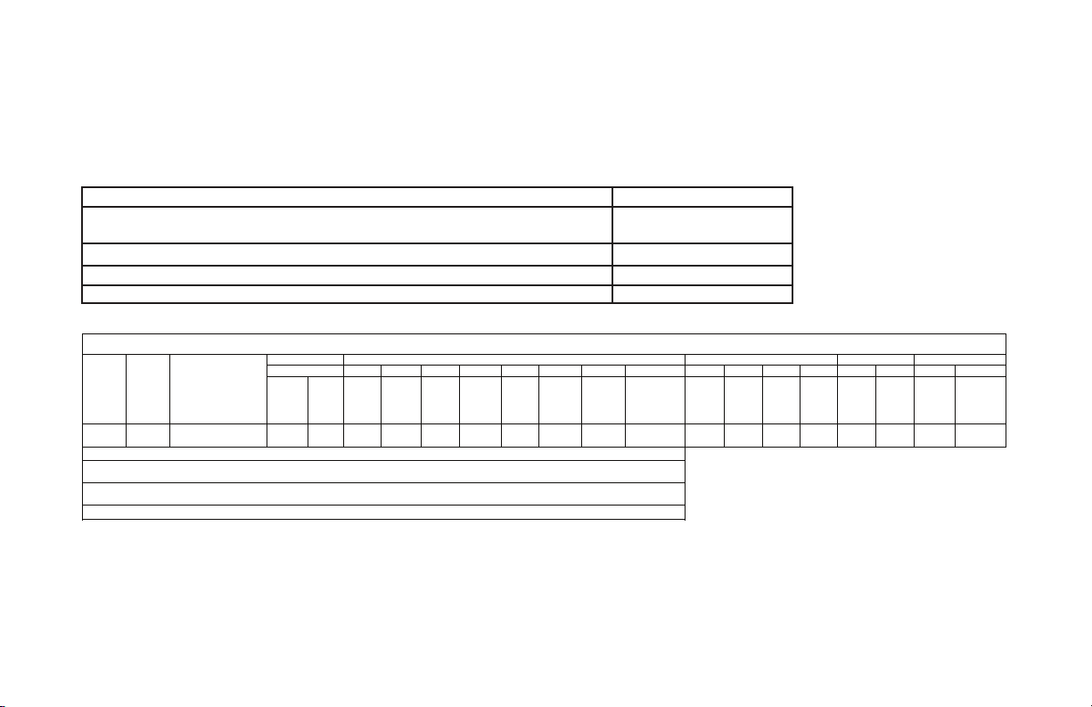
SERVICE ITEM SERVICE INTERVAL (FREQUENCY)
EVERY 6 MO. EVERY 12 MO. EVERY 36 MO.
OR OR OR
5,000 CYCLES 10,000 CYCLES 30,000 CYCLES
MANUAL
OPERATION OF
DOOR
DRIVE CHAIN
TENSION
PHOTOCELL/
*
SENSING EDGE
OPERATION
CLUTCH
ADJUSTMENT
BRAKE
ADJUSTMENT
CHECK FOR LOSE
OR MISSING
HARDWARE
CHECK LIMIT
POSITION
GEAR TRAIN
WEAR
*
ALL EXTERNAL REVERSING DEVICES SHOULD BE CHECKED MONTHLY.
GCL-MT
Medium Duty Operator
www.geniecompany.com 08-12
9.1
Page 41

Basic Operator Parts
Section 10: Appendix A
137
135
SEE SEPARATE ILLUSTRATED
PARTS LIST FOR INTERMEDIATE
SHAFT ASSY
SEE SEPARATE ILLUSTRATED
PARTS LIST FOR OUTPUT
SHAFT ASSY
GCL-MT
23
21 22
Medium Duty Operator
138
134
SEE SEPARATE ILLUSTRATED
PARTS LIST FOR ELECTRIC BOX
& LIMIT SHAFT
160
161
39
164
161
1
159
136
PARTS LIST
ITEM
NO.
110380**
1
110847**
21
110450.0001
22
110449.0001
23
110443**
39
110522.0001
134
135
110521.0001
136
110808.0001.S
110549.0001
137
110824.0001.S
138
111051.0002
159
160
111051.0001
161
110803.0001.S
111804.0001.S
164
** CONTACT DEALER FOR PROPER PART
BASED ON YOUR SPECIFIC MODEL.
www.geniecompany.com 08-12
DESCRIPTIONPART NUMBER
ELECTRIC MOTOR
BRAKE SOLENOID
BRAKE BAND
BRAKE RELEASE LEVER
BAND BRAKE PULLEY
BRAKE POST—FLOATING
BRAKE POST—FIXED
BRAKE ADJUSTMENT PLATE
BRAKE SOLENOID COVER
BRAKE RELEASE SPRING
OPERATOR CHASSIS RIGHT
OPERATOR CHASSIS LEFT
SUPPORT BRACE
SUPPORT BRACKET
10.1
Page 42

Basic Shaft Assembly Parts
20
21 22 23 24 25 26 27 14
15 17 16 15
19
Appendix A (cont’)
6
3
4
OUTPUT SHAFT ASSEMBLY
18 17 14
13
1
2
4 3
6
7
8
PARTS LIST
ITEM
NO.
1 086563.0001
2
110526.0001
080415.0021
3
110819.0001
4
5
110818.0001
106062.0003
5
6
7
8
13
14
15
16
17
18
19
20
21
22
23
24
25
26
27
110520.0001
107894.0001
110465.0001
080415.0021
110819.0001
110818.0001
110813.0001
110464.0001
110881.0001
080401.0624
110472.0001
075197.0000
086649.0029
111125.0001
108015.0001
075193.0000
111037.0001
DESCRIPTIONPART NUMBER
SPRKT, 14T, 1/4P, 1/2B
SPRKT, 19T, #35CH, 3/8P
E-RING
PLAIN WASHER
WAVE WASHER
BUSHING, 5/8
TROLLEY OUTPUT SHAFT
SPRKT, 9T, 1/2P DB
SPRKT, 11T, #35CH, 3/8P
E-RING
PLAIN WASHER
WAVE WASHER
BEARING, .625 ID
INTERMEDIATE TROLLEY SHAFT
DOWEL PIN
COTTER PIN
SLOTTED NUT
CLUTCH SPRING
THRUST WASHER
CLUTCH PULLEY
MOVABLE CLUTCH DISC
CLUTCH LINING
CLUTCH DISC
GCL-MT
Medium Duty Operator
www.geniecompany.com 08-12
10.2
Page 43

Basic Rail/Trolley Parts
Appendix A (cont’)
** CONTACT DEALER FOR PROPER PART
54 53
58 174 173 172
GCL-MT
60
Medium Duty Operator
77
77 64175
PARTS LIST
ITEM
PART NUMBER
NO.
108380.0001
53
54
086621.0672
58
076169.0000
60
110999.0001
61
110997.0001
64
110972.0001*
77
407743**
172
110843.0001
173
26013D
174
110842.0001
175
110920.0001
176
100132.0001
* INCLUDES PARTS 60, 174 AND 175.
** CONTACT DEALER FOR PROPER PART BASED ON
YOUR SPECIFIC INSTALLATION. PLEASE KNOW
61
THE LENGTH OF YOUR RAIL WHEN ORDERING.
www.geniecompany.com 08-12
DESCRIPTION
TROLLEY CHAIN IDLER PULLEY
TROLLEY IDLER SHAFT
TROLLEY RAIL FRONT SPREADER BRACKET
TROLLEY RAIL CHAIN GUIDE ASS’Y
TROLLEY RAIL CARRIAGE ASS’Y
TROLLEY HARDWARE KIT
TROLLEY RAIL
TROLLEY STRAIGHT DOOR ARM
TROLLEY CURVED DOOR ARM
TROLLEY DOOR BRACKET
TROLLEY TRACK SPACER
HAND GRIP
10.3
Page 44

Basic Electric Box Parts
35
Appendix A (cont’)
20
GCL-MT
12
Medium Duty Operator
140
139
139
PARTS LIST
ITEM
PART NUMBER
14
2
13
19
www.geniecompany.com 08-12
NO.
110405.0001.S
2
110405.0002.S
12
112365.0001.S
13
110846.0001
110846.0002
36424R
14
110957.0001.S
NS
110966.0001.S
20
19
110830.0001
110830.0002
35
110851.0001
139
110423.0001
140
110870.0001
37417A
141
NS=NOT SHOWN
** CONTACT DEALER FOR PROPER PART
BASED ON YOUR SPECIFIC MODEL.
DESCRIPTION
ELECTRICAL BOX, 115V
ELECTRICAL BOX, 230V
KIT, PCB
TRANSFORMER, 120V
TRANSFORMER, 240V
RADIO RECEIVER ASSERMBLY
FUSE KIT
LIMITSHAFT KIT
CAPACITOR, 79
CAPACITOR, 19
COVER ASSY. ELEC BOX
ELECTRIC BOX COVER HINGE
ELECTRIC BOX LATCH
MAIN CIRCUIT BOARD
10.4
Page 45

Screw Terminal Assignments
11-POSITION
INPUT
TERMINAL BLOCK
INSIDE ELECTRIC BOX
2-POSITION TERMINAL
BLOCK
(INSIDE ELECTRIC BOX)
OPEN
CLOSE
STOP
GND
1-BTN
ODC STB
ODC STB
N-O REVERSE
N-O REVERSE
EXT INTLK
EXT INTLK
L1 / L1
N / L2
Causes door to open if not at Up Limit.
Causes door to close if not at Down Limit.
Causes a moving door to stop.
Common ground connection for Open, Close, Stop &
Causes door to open if not at Up Limit or Mid-Stop Limit.
Causes door to close if at Up Limit or Mid-Stop Limit.
Causes door to stop if opening.
Reverses a closing door if photocell beam is blocked.
NOTE: STB's must be enabled in Calibration Mode.
Reverses a closing door if photocell beam is blocked.
NOTE: STB's must be enabled in Calibration Mode.
Causes a closing door to reverse.
Causes a closing door to reverse.
Causes a moving door to stop.
Prevents the operator from running when contact is open.
Operates even if microcontroller is non-functional.
Causes a moving door to stop.
Prevents the operator from running when contact is open.
Operates even if microcontroller is non-functional.
Power to operator.
Power to operator.
Other Connections
RADIO AND
ACCESSORIES
PLUG CONNECTIONS
INSIDE ELECTRIC BOX
PIGTAIL
PWR
RAD
(Radio Input Control)
GND
EXPANSION PORT
TRANSFORMER
BRAKE
MOTOR
HOIST INTLK
LIMIT SENSOR
Power for radio & other accessories.
Causes door to open if not at Up Limit or Mid-Stop Limit.
Causes door to close if at Up Li
Causes a closing door to reverse.
Common ground connection for PWR and RAD terminals. Connect to radio or other accessory's ground input.
Connects accessory modules to operator.
Connects main transformer to control board.
Connects brake solenoid to control board.
Connects motor and capacitor to control board.
Causes moving door to stop. Prevents the operator from running.
Operates even if microcontroller is non-functional.
Causes door to stop at top and bottom of normal travel.
Section 10: Appendix B
FUNCTION CONNECTION TYPE
Causes a closing door to reverse.
Prevents the operator from running.
1-Btn Inputs.
Causes a closing door to reverse.
NOTE: Will not open a stopped door.
NOTE: Will not open a stopped door.
+20 to +40VDC, fused at 250mA (F1).
mit or Mid-Stop Limit.
Normally-Open Dry Contact to GND.
Normally-Open Dry Contact to GND.
Normally-Closed Dry Contact to GND.
Normally-Open Dry Contact to GND.
ODC Series II Safe-T-Beams® ONLY to these inputs.
ODC Series II Safe-T-Beams® ONLY to these inputs.
Normally-Open 2-Wire Non-Monitored Edge Sensor.
Normally-Open 2-Wire Non-Monitored Edge Sensor.
Normally-Closed dry contacts.
(board will energize these contacts at nominal +24VDC).
Normally-Closed dry contacts.
(board will energize these contacts at nominal +24VDC).
120VAC: Connect to Line (Hot) / 240VAC: Connect to Line 1.
120VAC: Connect to Neutral / 240VAC: Connect to Line 2.
Connect to radio or other accessory's power input.
Connect to radio or other accessory's signal (output).
Accessory Module Ribbon Cable.
Transformer Plug.
Brake Solenoid Plug.
Motor Plug.
Hoist Interlock Plug or Jumper.
Limit Sensor Plug.
(not polarity sensitive)
(not polarity sensitive)
(not polarity sensitive)
(not polarity sensitive)
GCL-MT
Medium Duty Operator
www.geniecompany.com 08-12
10.5
Page 46

Display Run Codes
Condition
0C IDLE > DOWN LIMIT STANDING BY AT DOWN LIMIT (NOTE: THIS MESSAGE IS DISPLAYED IF BOTH LIMITS ARE ACTIVE)
0D
0E I DLE
0F
10 OPENING
11 OPENING
12 OPENING
13 OPENING
14 OPENING
20 CLOSING
21 CLOSING
22 CLOSING
24 CLOSING
2A CLOSING
30 HALT
31 HALT
32 HALT
33 HALT
34 HALT
35 HALT
36 HALT
37 HALT
38 HALT
39 HALT
3A HALT
3B HALT > SHUTDOWN GDO STOPPED BECAUSE THE GDO DETECTED A FAULT SUCH AS AN OPEN INTERLOCK, OVERHEATED MOTOR, ETC.
3C HALT
3D HALT
3E HALT
3F HALT
Code
DISPLAY
ID LE > U P LI MIT
>
MID STOP STANDING BY AT MID-STOP LIMIT
ID LE > N O L IMIT
>
OPEN BTN OPENING FROM OPEN BUTTON
>
ONE BTN OPENING FROM 1 BUTTON
>
RADIO OPENING FROM RADIO
>
AUX OPEN OPENING FROM AUXILIARY OPEN INPUT
>
OPEN KEY OPENING FROM KEYPAD OPEN KEY
>
CLOSE PB CLOSING FROM CLOSE BUTTON
>
ONE BTN CLOSING FROM 1 BUTTON
>
RADIO CLOSING FROM RADIO
>
CLOSE KP CLOSING FROM KEYPAD CLOSE KEY
>
TCM CLS CLOSING FROM TIMER CLOSE MODULE
>
WALL BUTTON GDO STOPPED BECAUSE STOP OR OPEN BUTTON WAS ACTIVATED, POSSIBLY STARTING A REVERSAL
>
ONE BUTTON GDO STOPPED BECAUSE 1 BUTTON WAS ACTIVATED, POSSIBLY STARTING A REVERSAL
>
RADIO GDO STOPPED BECAUSE RADIO INPUT WAS ACTIVATED, STARTING A REVERSAL
>
AUX. OPEN GDO STOPPED BECAUSE AUXILIARY OPEN INPUT WAS ACTIVATED, STARTING A REVERSAL
>
KEYPAD KEY GDO STOPPED BECAUSE KEYPAD STOP OR OPEN KEY WAS ACTIVATED, POSSIBLY STARTING A REVERSAL
>
N-O SAFETY GDO STOPPED BECAUSE N-O REVERSING INPUT WAS ACTIVATED, STARTING A REVERSAL
>
ODC STB GDO STOPPED BECAUSE ODC STB WAS BLOCKED, STARTING A REVERSAL
>
N-C SAFETY GDO STOPPED BECAUSE N-C REVERSING INPUT WAS ACTIVATED, STARTING A REVERSAL
>
MON. EDGE GDO STOPPED BECAUSE MONITORED EDGE SENSOR INPUT WAS ACTIVATED, STARTING A REVERSAL
>
DOOR FORCE GDO STOPPED BECAUSE THE FORCE REQUIRED TO OPERATE THE DOOR WAS TOO HIGH, POSSIBLY STARTING A REVERSAL
>
LOSS OF C/C
>
DOWN LIMIT GDO STOPPED BECAUSE IT REACHED THE DOWN LIMIT
>
UP LIMIT GDO STOPPED BECAUSE IT REACHED THE UP LIMIT
>
MID STOP GDO STOPPED BECAUSE IT REACHED THE MID-STOP LIMIT
>
MODULE FAIL GDO STOPPED BECAUSE AN EXPANSION MODULE WAS NOT WORKING PROPERLY
Condition Code Description
STANDING BY AT UP LIMIT
STANDING BY BETWEEN LIMITS
GDO STOPPED BECAUSE CONSTANT CONTACT ON THE CONTROL WAS REMOVED BEFORE REACHING A LIMIT, POSSIBLY STARTING A REVERSAL
Section 10: Appendix C
GCL-MT
Medium Duty Operator
www.geniecompany.com 08-12
10.6
Page 47

Display Error Codes
Condition
40 REV
41 REV
42 REV
43 REV
44 REV
45 REV
46 REV
47 REV
48 REV
49 REV
4A REV
4B REV
4F REV > EXP MOD FAIL GDO REVERSED BECAUSE AN EXPANSION MODULE WAS NOT WORKING PROPERLY
50 STOP
51 STOP
52 STOP
57 STOP
58 STOP
59 STOP
5A STOP
5C STALL
5D STALL
60 CHECK STOP BTN GDO WON'T RUN BECAUSE THE STOP BUTTON IS ACTIVE
61 TCM DISABLED TIMER CLOSE WON'T WORK BECAUSE NO SAFETIES ARE ENABLED
62 NO RADIO
63 CHECK AUX OPEN GDO WON'T CLOSE BECAUSE AUXILIARY OPEN INPUT IS ACTIVE
64 CHECK STOP KEY GDO WON'T RUN BECAUSE THE KEYPAD STOP KEY IS ACTIVE
65 CHECK N-O SAFET Y GDO WON'T CLOSE BECAUSE THE N-O REVERSING IS ACTIVE
66 CHECK ODC STB GDO WON'T CLOSE BECAUSE THE ODC STB IS BLOCKED
67 CHECK N-C SAFET Y GDO WON'T CLOSE BECAUSE THE N-C REVERSING INPUT IS ACTIVE
68 CHECK MON. EDGE GDO WON'T CLOSE BECAUSE THE MONITORED EDGE SENSOR IS ACTIVE
69 OVERHEATED MOTOR GDO WON'T RUN BECAUSE THE MOTOR IS OVERHEATED
6C NO RUN
6D NO RUN
6E NO RUN
GCL-MT
Code
6F EXP MODULE FAIL GDO WON'T RUN BECAUSE AN EXPANSION MODULE FAILURE IS PREVENTING IT
Medium Duty Operator
DISPLAY
>
OPEN BUTTON GDO REVERSED BECAUSE THE OPEN BUTTON WAS ACTIVATED
>
ONE BUTTON GDO REVERSED BECAUSE THE 1 BUTTON WAS ACTIVATED
>
RADIO GDO REVERSED BECAUSE THE RADIO INPUT WAS ACTIVATED
>
AUX OPEN GDO REVERSED BECAUSE THE AUXILIARY OPEN INPUT WAS ACTIVATED
>
OPEN KEY GDO REVERSED BECAUSE THE KEYPAD OPEN KEY WAS ACTIVATED
>
N-O SAFETY GDO REVERSED BECAUSE THE N-O REVERSING INPUT WAS ACTIVATED
>
ODC STB GDO REVERSED BECAUSE THE ODC STB WAS BLOCKED
>
N-C SAFETY GDO REVERSED BECAUSE THE N-C REVERSING INPUT WAS ACTIVATED
>
MON. EDGE GDO REVERSED BECAUSE THE MONITORED EDGE SENSOR WAS ACTIVATED
>
DOOR FORCE GDO REVERSED BECAUSE THE FORCE REQUIRED TO CLOSE THE DOOR WAS TOO HIGH
>
LOSS OF C/C GDO REVERSED BECAUSE CONSTANT CONTACT ON THE CONTROL WAS REMOVED BEFORE REACHING THE DOWN LIMIT
>
MAX RUN TMR GDO REVERSED BECAUSE THE CLUTCH SLIPPED OR SOME OTHER FAULT OCCURRED THAT ALLOWED THE GDO TO RUN TOO LONG
>
HOT MOTOR GDO STOPPED BECAUSE THE MOTOR WAS OVERHEATED
>
OPEN MRT GDO STOPPED BECAUSE THE CLUTCH SLIPPED OR SOME OTHER FAULT OCCURRED THAT ALLOWED THE GDO TO RUN OPEN TOO LONG
>
CLOSE MRT GDO STOPPED BECAUSE THE CLUTCH SLIPPED OR SOME OTHER FAULT OCCURRED THAT ALLOWED THE GDO TO RUN DOWN TOO LONG
>
OPEN INTLK GDO STOPPED BECAUSE THE HOIST INTERLOCK OR EXTERNAL INTERLOCK IS OPEN
>
WRONG GDO GDO STOPPED BECAUSE THE BOARD IS SET FOR JACKSHAFT MODE, BUT INSTALLED IN A TROLLEY OPERATOR
>
DOOR FORCE GDO STOPPED BECAUSE THE FORCE REQUIRED TO OPEN THE DOOR WAS TOO HIGH
>
WRONG LIMIT GDO STOPPED BECAUSE THE UP LIMIT ACTIVATED WHEN CLOSING OR THE DOWN LIMIT ACTIVATED WHEN OPENING
>
DOWN LIMIT GDO STOPPED BECAUSE IT COULDN'T LEAVE THE DOWN LIMIT DUE TO A SLIPPING CLUTCH OR OTHER PROBLEM
>
UP LIMIT GDO STOPPED BECAUSE IT COULDN'T LEAVE THE UP LIMIT DUE TO A SLIPPING CLUTCH OR OTHER PROBLEM
>
>
>
Section 10: Appendix C
>>
C/C RADIO INPUT WON'T WORK WITH OPEN OR CLOSE FUNCTION IN CONSTANT CONTACT MODE
DOWN LIM GDO WON'T CLOSE BECAUSE ITS ALREADY AT THE DOWN LIMIT
UP LIMIT GDO WON'T OPEN BECAUSE ITS ALREADY AT THE UP LIMIT
MID STOP GDO WON'T RUN BECAUSE ITS AT OR ABOVE THE MID-STOP LIMIT & CAN'T RUN UP & A REVERSING INPUT IS PREVENTING IT FROM CLOSING
Condition Code Description
www.geniecompany.com 08-12
10.7
Page 48

Section 10: Appendix C
Display Error Codes (cont’)
Condition
Code
70 BOARD FAILURE 70 CONTROL BOARD FAILURE 70, CONTACT FACTORY TECHNICAL SERVICE DEPT.
71 BOARD FAILURE 71 CONTROL BOARD FAILURE 71, CONTACT FACTORY TECHNICAL SERVICE DEPT.
74 BOARD FAILURE 74 CONTROL BOARD FAILURE 74, CONTACT FACTORY TECHNICAL SERVICE DEPT.
75 BOARD FAILURE 75 CONTROL BOARD FAILURE 75, CONTACT FACTORY TECHNICAL SERVICE DEPT.
76 BOARD FAILURE 76 CONTROL BOARD FAILURE 76, CONTACT FACTORY TECHNICAL SERVICE DEPT.
77 BOARD FAILURE 77 CONTROL BOARD FAILURE 77, CONTACT FACTORY TECHNICAL SERVICE DEPT.
80 BOARD FAILURE 80 CONTROL BOARD FAILURE 80, CONTACT FACTO
81 BOARD FAILURE 81 CONTROL BOARD FAILURE 81, CONTACT FACTORY TECHNICAL SERVICE DEPT.
82 BOARD FAILURE 82 CONTROL BOARD FAILURE 82, CONTACT FACTORY TECHNICAL SERVICE DEPT.
83 BOARD FAILURE 83 CONTROL BOARD FAILURE 83, CONTACT FACTORY TECHNICAL SERVICE DEPT.
84 BOARD FAILURE 84 CONTROL BOARD FAILURE 84, CONTACT FACTORY TECHNICAL SERVICE DEPT.
85 EXP PORT PROBLEM EXPANSION PORT IS SHORT CIRCUITED, TRY DISCONNECTING EXPANSION MODULES OR CONTACT FACTORY TECHNICAL SERVICE DEPT.
86 BOARD FAILURE 86 CONTROL BOARD FAILURE 86, DISCONNECT EXPANSION MODULES. IF NO CHANGE, CONTACT FACTORY TECHNICAL SERVICE DEPT.
88 TCM FAILURE TIMER CLOSE MODULE (TCM) HAS FAILED
8A AOM FAILURE AUXILIARY OUTPUT MODULE (AOM) HAS FAILED
8E REV INTERRUPTED GDO LOST POWER OR ENCOUNTERED ANOTHER PROBLEM DURING THE REVERSAL PROCESS, REVERSAL IS COMPLETING NOW
8F LIMIT MOD. FAIL
90 DIAGNOSTIC MODE GDO IS IN DIAGNOSTIC MODE, NORMAL FUNCTIONS ARE NOT ALLOWED
A0 OPEN BTN BAD > PU OPEN & CLOSE BUTTONS WON'T WORK, THE OPEN BUTTON WAS ACTIVE WHEN THE GDO WAS POWERED-UP
A1 CLOSE BTN BAD > PU OPEN & CLOSE BUTTONS WON'T WORK, THE CLOSE BUTTON WAS ACTIVE WHEN THE GDO WAS POWERED-UP
A2 ONE BTN BAD > PU 1 BUTTON WON'T WORK, THE 1 BUTTON WAS ACTIVE WHEN THE GDO WAS POWERED-UP
A3 RADIO BAD > PWR UP RADIO INPUT WON'T WORK, THE RADIO INPUT WAS ACTIVE WHEN THE GDO WAS POWERED-UP
A4 AUX OPEN BAD > PU AUXILIARY OPEN INPUT WON'T WORK, THE AUXILIARY OPEN INPUT WAS ACTIVE WHEN THE GDO WAS POWERED-UP
A5 OPEN KEY BAD > PU KEYPAD OPEN & CLOSE KEYS WON'T WORK, THE OPEN KEY WAS ACTIVE WHEN THE GDO WAS POWERED-UP
A6 CLOSE KEY BAD > PU KEYPAD OPEN & CLOSE KEYS WON'T WORK, THE CLOSE KEY WAS ACTIVE WHEN THE GDO WAS POWERED-UP
A7 MULT KEYS BAD > PU 1 OR MORE KEYPAD CALIBRATION KEYS WON'T WORK, 1 OR MORE WERE ACTIVE WHEN THE GDO WAS PO
AA TCM BAD > POWER UP TIMER CLOSE MODULE WON'T CLOSE DOOR, IT WAS ACTIVE WHEN THE GDO WAS POWERED-U
DISPLAY
Condition Code Description
GDO WON'T RUN, LIMIT MODULE HAS FAILED
RY TECHNICAL SERVICE DEPT.
WERED-UP
GCL-MT
Medium Duty Operator
www.geniecompany.com 08-12
10.8
Page 49

Commercial Operator Limited Warranty
Two (2) years or When the Operator exceeds 20 000 cycles of operation as measured by the
integrated cycle counter contained in the Operator.
GCL-MT
Medium Duty Operator
ORIGINAL PURCHASER
(“Product”) subject to all of the terms and conditions hereof that the Product and all components
The Genie Company ("Seller") warrants to the original purchaser of this commercial door operator
thereof will be free from defects in materials and workmanship under normal use for the following
period(s) measured from the date of installation
Seller’s obligation under this warranty is specifically limited to repairing or replacing at its option any
part which is determined by Seller to be defective during the applicable warranty period. Any labor
www.geniecompany.com 08-12
This warranty does not apply to any unauthorized alteration or repair of the Product or to any Product or
component which has been damaged or deteriorated due to misuse neglect accident failure to provide
necessary maintenance normal wear and tear or acts of God or any other cause beyond the reasonable
control of Seller.
charges are excluded and will be the responsibility of the purchaser.
This warranty is made to the original purchaser of the Product only and is not transferable or assignable.
THIS WARRANTY IS EXCLUSIVE AND IN LIEU OF ANY OTHER WARRANTIES EITHER
EXPRESSED OR IMPLIED INCLUDING BUT NOT LIMITED TO ANY IMPLIED WARRANTY OF
MERCHANTABILITY OR FITNESS FOR A PARTICULAR PURPOSE.
IN NO EVENT SHALL SELLER BE RESPONSIBLE FOR OR LIABLE TO ANYONE FOR SPECIAL
Seller has been advised of the possibility of such damages. Such excluded damages include but are
not limited to loss of goodwill loss of profits loss of use cost of any substitute product interruption of
business or other similar indirect financial loss.
Claims under this warranty must be made promptly after discovery within the applicable warranty period
and in writing to the Seller or to the authorized distributor or installer whose name and address appear below.
The purchaser must allow Seller a reasonable opportunity to inspect any Product claimed to be defective
prior to removal or any alteration of its condition. Proof of the purchase and/or installation date and
INDIRECT COLLATERAL PUNITIVE INCIDENTAL OR CONSEQUENTIAL DAMAGES even if
identification as the original purchaser may be required.
INSTALLATION ADDRESS
SELLER:
SELLER S ADDRESS:
FACTORY ORDER #:
DATE OF INSTALLATION:
SIGNATURE OF SELLER:
11.1
Page 50

THIS PAGE LEFT BLANK
GCL-MT
Medium Duty Operator
www.geniecompany.com 08-12
Page 51

THIS PAGE LEFT BLANK
GCL-MT
Medium Duty Operator
www.geniecompany.com 08-12
Page 52

One Door Dr.
Mt. Hope, OH 44660
 Loading...