


REFERENCE ONLY
[I
236507
[I
•
,
,
•
~
~

REFERENCE ONLY
Table of Contents
Foreward ..........................................
Safety Precautions
Identification Of The Axle ...........
Cleaning and Inspection
Lubrication Specifications
Torque Limits and Specifications
Exploded View
Parts List
Axle Assembly Instructions ......
Differential Tooth Contact Charts ..........................
Maintenance Intervals and Procedures
Symbols
Model 25S34 Disassemby .............
Removal of Wheel Ends
Removal of Drive Flange
Removal of Axle Assembly .......................................... ......................................................
Disassembly of Drive Flange and Steer Knuckle
...
..
.................
..
....
..............
..
....................................................................
.....................................................................................................
..
..............................
........
...
.....................
...
..................................................................................................
...
..
............................................................
..............
.... .....
.......... ..
...................
..
.. ..
............
.....
..............................................................
...
............. : ................
.............................................
..................................
..
................................................................................
..
......
...................................................................................
.........
...................
...
....................................
........................................
............... ..
..
................................
.....................
..
....
.. ..
...
..................
..........................................................
.............
................................................. 13
...
....................
....
........................................
................................. 1
...
........................................ 2
...
.......
....
.......
...
........................................ 4
.................... ............. 7
.......
..................... ..
..................................
.......
...
...............
...
...........
.....................
...
.................. 3
...
...... 6
. 11-12
...
...... 18
............... 19
...
...
.. .........
.. ............ 23
...
...
..
..
10
16
20
20
21
23
....
Removal and Disassembly of Front and Rear Trunnions ....................
..
Removal and Disassembly of Steer Cylinder
Removal of Seals and Bushings from Ax
le
Removal of Ax
Disassembly of Carrier ....
Disassembly of Inner
Reassembly of Model 25S34 .
Reassembly of Trunnions .........
Reassembly of Carrier Housing ........
Pinion Shim Selection ...............................................
Pinion Shim Selection Cha
Reassembly of Axle Housings .................
Reassembly of Wheel Ends
Reassembly of Steer Cylinder .........
Installation of Front and Rear Trunnions ......................................
Bleeding The Brake System ......................................................................................................... 55 •
Housings ..................................................
........
....................................................
Yoke
and Shaft Assembly ............................
...
..............................................
..
.............
..
..........
rt .........................................................
.. ..
.........................................
....
......................................
...............................
le
Housings ..........................
.. ..
....................
...........
.....................................
.....................
.........
.......................................
....
.....................................
.... ..
........................................................ 38 4
.. .. ..
...
.......
...
......................................... 34
.......................................... 36
.. ....
.......................................... 39
...
...............
....
..........
...
..................................... 26
....
...............................
.............................
.........
............................... 44
...
.. ....
.........................
.... ........
............
...
........................ 36
....................
....
....................... 52 C
.......
..
25
27
...........
...
..
29
....
.......
31
..........
.............. 54 C
..
37
.......... 48 C
~
~
«:>1999
DANA CORPORATION
~
~
~

REFERENCE ONLY
..
MAINTENANCE MANUAL MOOEL
25534
AXLE
Foreward
This manual has been prepared to provide the customer and the maintenance personnel with
information and instructions on the maintenance and repair of the Spicer Off Highway Products.
Extreme care has been exercised in the design and selection of materials and manufacturing of
these units. The slight outlay
proper lubrication and inspection at stated intervals, and such adjustments as may be indicated
will be reimbursed many times
In
order to become familiar with the various parts of the product , it's principle of operation,
troubleshooting, and adjustments, it is urged that the mechanic study the instructions
manual carefully and use it as a reference when performing maintenance and repair operations.
Whenever repair
Products approved parts
or non-approved parts may endanger proper operation and performance of the equipment.
Spicer Off Highway products does not warrant repair or replacement parts, nor failures resulting
from the use of parts which are not supllied or approved by Spicer Off Highway Products.
Important: Always furnish the distributor with the serial and model number when ordering parts.
or
replacement of component parts is required, only Spicer Off Highway
as
in
personal attention and cost required to provide regular and
in
low cost operation and trouble free service.
listed
in
the applicable parts manual should
be
used. Use of "will fit"
in
this
1

REFERENCE ONLY
MAINTENANCE MANUAL MOOEL 25534
Safety Precautions
To
reduce the chance of personal injury and/or property damage, the following instructions
must be carefully observed .
Proper service and repair are important to the safety of the service technician and the safe,
reliable operation of the machine. If replacement parts are required the part must be replaced
with one
lesser quality.
of
the same part number or with an equivalent part. Do not use a replacement part of
The service procedures recommended
service and repair. Some of these procedures require the use of tools specifically designed for
the purpose.
Accordingly, anyone who intends to use a replacement part, service procedure or tool which is
not recommended must first determine that neither his safety nor the safe operation of the
machine will be jeopardized by the replacement part, service procedure or tool selected.
It
is important to note that this manual contains various 'Cautions' and 'Notices ' that must be
carefully observed in order to reduce the risk
possibility that improper service or repair may damage the unit or render it unsafe. It is also
important to understand that these 'Cautions' and 'Notices' are not exhaustive, because it is
of
impossible to warn
follow these instructions.
all the possible hazardous consequences that might result from failure to
in
this manual are effective methods of performing
of
personal injury during service or repair, and the
2
REFERENCE ONLY
MAINTENANCE MANUAL MODEL
25534
AXLE
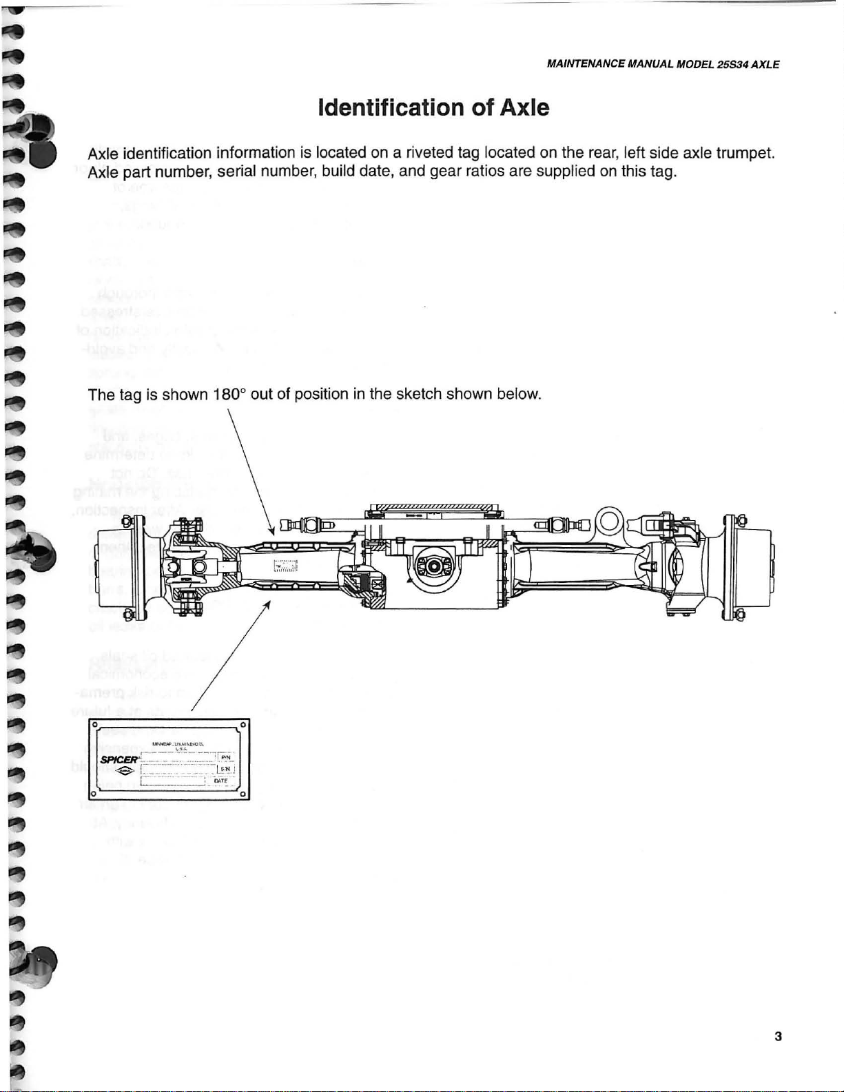
Identification
Axle identification information is located
Axle part number, serial number, build date, and gear ratios are supplied on this tag.
The tag is shown 180
0
out of position
on
a riveted tag located on the rear, left side axle trumpet.
in
the sketch shown below.
of
Axle
o
o
o
3
REFERENCE ONLY
MAINTENANCE MANUAL MODEL 25534
Cleaning and Inspection
Cleaning
Clean all parts thoroughly using solvent
type cleaning fluid.
parts be immersed in cleaning fluid and agitated slowy until parts are thoroughly cleaned
of all old lubricants and foreign materials.
It
is recommended that
Caution
Care should be exercised to avoid skin
rashes, fire hazards and inhalation of vapors
when using solvent type cleaners.
Bearings
Remove bearings from cleaning fluid and
strike larger side of cone flat against a bock of
wood to dislodge solidified particles of lubri-
in
cant. Immerse again
out particles . Repeat above operation until
bearings are thoroughly clean. When drying
bearings, use moisture-free compressed air,
being careful to direct air stream across bearings as to avoid spinning. Bearings may be
rotated slowly by hand to facilitate the drying
process.
cleaning fluid to flush
Thoroughly dry all parts cleaned immedi-
ately by using moisture-free compressed air or
soft lintless absorbent wiping rags free of
abrasive materials such as metal filings,
contaminated oil or laping compound.
Inspection
The importance of careful and thorough
inspection of all parts cannot be overstressed.
Replacement of all parts showing indication of
wear or stress will eliminate costly and avoid-
able failures at a later date.
Bearings
Carefully inspect all rollers, cages, and
cups for wear, chipping or nicks to determine
fitness of bearings for further use.
replace a bearing without replacing the mating
cup or cone at the same time. After inspection,
dip bearings in clean light oil and wrap in
clean lintless cloth or paper to protect them
until installed.
Do
not
Oil Seals, Gaskets and
Retaining Rings
Housing
Clean interior and exterior of housings,
bearing caps, etc., thoroughly. Cast parts may
be cleaned
alkali solutions, providing these parts do not
have ground or polished surfaces. Parts
should remain in solution long enough to be
throughly cleaned and heated. This will aid the
evaporation of the cleaning solution and rinse
water. Parts cleaned
throughly rinsed with clean water to remove all
traces of alkali. Cast parts may also be
cleaned with steam cleaner.
in
hot solution tanks with mild
in
solution tanks must be
Replacement of spring loaded oil seals,
gaskets, and snap rings is more economical
when unit is disassembled than to risk premature overhaul to replace these parts at a future
time. Loss of lubricant through a worn seal
in
may result
parts of the assembly. Sealing member should
be
handled carefully, particularly when being
installed. Cutting, scratching, or curling under
lip of seal seriously impairs its efficiency. At
reassembly, lubricate lips of oil seals with
Multipurpose Lithium grease. "Grade 2"
(MS107C).
failure of other more expensive
Caution
Care should be exercised to avoid skin
rashes and inhalation of vapors when using
alkali cleaners.
4

REFERENCE ONLY
MAINTENANCE MANUAL MODEL 25534
Cleaning and Inspection (Cont.)
AXLE
Gears and Shafts
If magna-flux process is available, use
process to check parts. Examine teeth and
ground
shafts carefully for wear, pitting, chipping,
nicks, cracks,
cracked
is worn through, replace with
nicks
Inspect shafts to
sprung, bent,
shafts are true. Differential pinions and side
gears
ring
placed as a set if either is damaged.
and
polished surfaces
or
scoring. If gear teeth are
or
show
spots
may
be removed with suitable hone.
make
or
splines twisted,
must
be replaced as sets. Differential
gear
and spiral pinion must also be re-
where case hardening
certain they are not
of
new
all gears and
gear. Small
and
that
Housing and Covers
Inspect housing, covers, planet spider, and
differential case to
oughly cleaned and
bearing bores, etc., are free from nicks or
burrs.
cracks
oil leaks
Check
or
condition which cause subsequent
or
failures.
be
certain they are thor-
that
mating surfaces,
all parts carefully
for
evidence
of
Torque values specified in text
B.B,
manual are for class
presently used in production. On all axles
being overhauled, bolts should
described above and torque value chart consulted
for
correct torque.
10.9 hardware where
of
this
be
identified as
At Reassembly
Apply Thread Locking
Compound Where Noted
Guidelines
A.
On
end) apply compound on female threaded
component part.
B.
On nuts, apply compound to the
thread
C. Apply compound to coat the full length
circumference
D.
Remove excess compound from mating
parts after fastener installation.
for
application where to apply:
bolts, capscrews, and studs (anchor
male
of
the mating fastener.
and
of
thread engagement.
Reassembly
The
reassembly instructions describe the
procedure to be followed when reassembling
and installing components of axle. Instructions
covering reassembly
cal unless otherwise noted.
Important: Class
fastening hardware have been used in the
production of the axle assemblies covered
the manual. A table of proper torque values
the fastener classes above are provided within
this manual. The class of hardware
determined by the markings contained on the
head
of
each capscrew. Class 12.9 torque
values needs to be used on all sockethead
caps crew used with this assembly.
of
Axle
of
opposite side is identi-
B.B
and 10.9 and 12.9
may
in
for
be
5

REFERENCE ONLY
MAINTENANCE MANUAL MODEL 25534
Lubrication Specifications
Recommended Lubricants
for
Spicer 25 S 34 Axle
Initial and Service Fill
Select high quality gear lubricant type GL5 that conforms to MIL-L-21
Select the highest
the oil application chart shown below.
oil
viscosity compatible with the prevailing ambient temperature
Capacities
Recommended
75W90
Each wheel end
Axle Center Section
Total
Axle
MI-l-21
050
Viscosity
Capacity
Grade
Based
13.5 qts.
16.5 qts.
on
Prevailinq
1.5 qts.
Ambient
05
specifications.
Temperature
as
shown
on
Celsius
Fahrenheit
Actuator
80W90
-40 -30 -15
-40
-22
5
Prevailing Ambient Temperatures
0
32
10
50
20
68
30
86
Internal Liquid Cooled Brake Fluids
oils
recommended
1. Motor oil
2.
Transmission lubricants meeting the following specs:
a)
Caterpillar TO-4
b)
John Deere J20
c)
Military MIL-PRF-2104G
d)
Allison C-4
3. Hydraulic
4. Synthetic gear oils
oil
for
use
in
API SE/CD
C,
the
D
liquid
40 49
104 120
cooled brake
circuit
6

REFERENCE ONLY
'W
Torque Limits and Specifications
Housing:
Housing ArmfTrumpet Bolts
Carrier Cover
Brake Port Fittings
Bleeder Screws
Differential Torques:
Adjusting Ring Clip Bolt
Drive Gear Capscrews
Cap Bolts
Pinion Nut
Wheel End Assembly:
Hub Retainer Capscrews (with Loctite 271)
Planetary Retaining Screws
Wheel End Fill/Drain Plug
MAINTENANCE MANUAL MODEL
110-120 ft-Ibs (156-162 Nm)
115-120 ft-Ibs (156-162 Nm)
7-10 ft-Ibs
7-10 ft-Ibs (9.5-13.5 Nm)
15-17 ft-Ibs
90-100 ft-Ibs (122-135 Nm)
75-90 ft-Ibs
220-280 ft-Ibs (298-380 Nm)
115-120 ft-Ibs (156-162 Nm)
110-120 ft-
40 -45 ft-
(9
.5-13.5 Nm)
(9
.5-13 .5 Nm)
(101
-122 Nm)
Ibs
(149-162 Nm)
Ibs
(54-61 Nm)
25534
AXLE
Knuckles and Steer Cylinder:
King Pin Retainer Bolts
U-Joint Flange Screws
Steer Cylinder Mounting Bolts
Tie Rod Socket Assembly (with Loctite 271)
ne
Rod Lock Nut
80-90 ft-Ibs (108-122 Nm)
55-60 ft-Ibs (74-81 Nm)
80-90 ft-Ibs (108-122 Nm)
192-207 ft-Ibs (260-280 Nm)
221
ft-Ibs (299 Nm)
7

REFERENCE ONLY
MAINTENANCE MANUAL MODEL 25534
Torque For Bolts, Capscrews, Studs and Nuts as Supplied
~
~
~
Grade 5 Identification,
Dashes 120
0
Apart
~
Grade
Fastener
Size
1/4-
20
1/4-28
5/16-18
5/16-24
3/8-16
3/
8-24
80-90 Lbs.
180-200 Lbs. In.
25-28 Lbs.
3 Radial
on
Head
5
Lubricated
In
.
Ft.
of
and
Grade 8
Bolt
Plated
[9-10 N.m] 110-120 Lbs. In.
[21-23 N.m] 215-240 Lbs. In.
[34-38 N.
Dashes 600 Apart
m)
35-40 Lbs. Ft.
Identification,
on
Head
®
Grade 8
Lubricated
and
6 Radial
of
Bolt
Plated
[13-14 N.m)
[24-27 N.
[48-54 N.
m)
m)
7/16-14
7/16
-
20
1/
2-13
1/2-20
9/16-12
9/16-18
5/
8-11
5/8-18
3/
4-10
3/4-16
7/8-9
7/8-14
1-8
1-12
1-1
/8-7
1-1
/8-12
1-1/4-7
1-1
/4-12
40-45 Lbs.
65-70 Lbs.
90-100 Lbs. Ft. [125-135 N.
125-140 Lbs.
220-245 Lbs.
330-360 Lbs.
475-525 Lbs.
650-720 Lbs.
900-1000 Lbs.
Ft.
Ft.
Ft.
Ft.
Ft.
Ft.
Ft.
Ft.
[54-61 N.m)
[88-95 N.m]
[170-190 N.m] 175-190 Lbs . Ft.
[300-330 N.m]
[450-490 N.
[645-710 N.m] 725-800 Lbs.
[880-975 N.m] 1050-1175 Lbs. Ft.
[1220-1360 N.m) 1475-1625 Lbs. Ft.
m)
m)
Lb
s.
60-65
90-100 Lbs.
125-140 Lbs.
300-330 Lbs. Ft. [410-450 N.
475-525 Lbs.
Ft.
Ft.
Ft.
Ft.
Ft.
[82-88 N.
[125-135 N.
[170-190 N.m]
[240-260 N.m]
[645-710 N.m]
[985-1085 N.m]
[1425-1600 N.m]
[2000-2200 N.m]
m]
m)
m]
,,
:
8

REFERENCE ONLY
...
MAINTENANCE MANUAL MODEL 25534
TorquelTension Charts
Coarse Threated Fasteners Coarse Threated Fasteners
Thread
Class
M5XO
M6X1
M8X1.25
M10X1 .5
M12X1.75
M14X2
M16X2
M20X2.5
M24X3
M30X3.5
M36X4
Size
B.B
.8
Tor~ue
Nm
5-6 43-53
8-10 71-88
20-25 177-221
40-45
70-78 52-59
110-125 81-92
170-190 125-140
340-380 251-280
580-650
1150-1300 848-959
2000-2250
Lb-Ft
Lb-In
30-33
428-479
1479-1660
Thread Size
Class
10.9
M5XO.8 7-8
M6X1 12-14
M8X1.25 30-35
M10X1.5 60-65 40-48
M12X1.75 100-110
M14X2 155-180 114-133
M16X2 240-270
M20X2.5 450-500
M24X3
M30X3.5 1600-1800
M36X4
Nm Lb-In
800-900
2800-3150 2065-2323
Torque
AXLE
62-71
106-124
Lb-Ft
22-26
74-81
177-199
332-369
590-664
1180-1328
SAE
"
0"
Coarse Threated Fasteners
Thread
Class 12.9
Size
Nm Lb-In
M5XO
.8
M6X1
M8X1.25
M10X1.5
M12X1.75
M14X2
M16X2 280-320 207-236
M20X2.5
M24X3 900-1050 664-774
M30X3.5 1850-2100 1364-1549
M36X4
8-10
14-16 124-142
34-40
70-75
115-130
180-210
550-600
3250-3700 2397-2729
Torque
71-88
Lb-Ft
26-30
52-55
85-96
133-155
406-443
.3125-24
.3750-24
.4375-20
.5000-20
.5625-18
.7500-16
.8750-14
1.0625-12
1
1.6250-12
1.8750-12
Ring Thread
Thread
Size
.3
125-12 88-102
Nm
4-7
7-11
9-13
14-18
16-20
27-34
41-47
61-38
102-115
102-115 75-85
Torque
Lb-Ft
3-5
5-8
7-10
10-1
12-15
20-25
30-35
45-50
65-75
75-85
3
NOTE: Socket head capscrews are all Class 12.9
9

REFERENCE ONLY
~
o
23
"
(J-::-::
~
27
"-
31
30
~
ms:
><
0
~a,
o
CD
a,-
CD
I\)
16
a,CJ1
<C/)
~.
~
:;;
n1
~
~
~
>e
~
....
g
143
~
~
'"
'"

REFERENCE ONLY
MAINTENANCE MANUAL MODEL
25534
AXLE
Model
Item
No. Description
1 Carrier Sub·Assy
2 Bearing Cup-Roller
3 Bearing
4 Shim-ADJ
5 Gear
6 Spacer-Collapsible
7 Bearing Cup-Roller
8 Bearing Cone-Roller ....
9 Thrustwasher-Brg
1 0 Seal-Oil ................
11
Deflector-Seal ......
12
End
13
Washer-Pinion Nut .....
14 Nut-Pinion ...........
15 Case (Diff
16
Thrustwasher-Differential Gear
17 Gear-Differential
18
Thrustwasher-Differential Pinion ...................... 2
19
Pinion-Differential .........................
20 Shaft-Differenti
21
Pin-Roll ..........
22 Bearing Cone-Roller
23
Gear & Pinion Assy-Spiral Bevel .......
24 Screw-Drive Gear ...........................
25 Bearing Cup-Roller ....................
26 Cap-Differential Brg (Part of Iteml) .......
27 Bolt-Hex .......
28
Ring-Adjusting
Cl
29
30 Washer-Flat .......
31
Bolt-Hex ........
32
Co
33
Washer-Flat .................
34 Bolt-Hex ...........................................................
35
Plug-Pipe (Internal Drive) ................................. 1
36
Plug-Pipe (Inte
37
Plate-Spring
38
Spring-Compressi
39
Glyd
40
Ring-O Inner ..........................................
41 Piston-Park .............................
42
Ring-O Outer .................................................... 2
43
Glyd
Con
& Pinion Assy-Spiral
Yoke
ip-Adjusting Ring .............
ver-Carrier .................................................... 1
Ring
Ring
..
........................
..
......................................... 1
e-Roller ............
..........
...
....................................
Bevel
..
.......................
...
........................................ 1
........
.....
...........
..
........................................... 1
........
...............
..........................................................
........
.........
.....................................
Std)
.................................................. 1
.............
al
Std & TIL
......
...
................................ ................. 4
......
.................
........................
rnal
Backing ........................................ 2
Inner .
........
Outer ..........
.................................. 2
.......... ................................... 1
..
....................................... 2
............................................ 2
...........
Drive) ................................. 1
on
........................................ 20
............
...........................
....
................ 1
...
.......................
...
...................... 1
............
........
..................... 1
..................
........
.............
............................
.............................. 2
............................
.......
......
....
..
........................ 2
.... ..
...
................... 1
...
............
........... 2
....
................ 2
....
........... 1
..
.............
...
.......
............. 2
......
..............
...................
.....................
....
........... 2
25534
Parts List
Item
Qty.
44
45
...
..... 1
...... 1
..... 1
...
....
...
..
12
....
. 2
..
.....
..
12
12
..
....... 2
1
1
1
1
1
2
2
2
46
47
48
49
50
51
52
53
54
55
56
57 Coupling-Splined ................................................ 2
58
59
60
61
62
63
64
65A Shaft-Axle Right
65B
66 Washer-Flat .......................................................
67 Bolt-Hex ............................................................. 32
68
69
70 Fitling-Hyd Brake .......................................
71
72 Screw-Flange
73 Ring-Snap .........
74
75
76
77 Seal-Oil .......................
78 Seal-Oil .............
79 Bushing-Spindle ..........................
80
81
82 Retainer-Grease
83 Bearing
84
85
Axle
No. Description
Yoke-Center
Cross-U Join!.. .... ............................................... 4
Seal Assy ......
Bearing
Ring-Snap .....................................
Housing-
Tilt
Eye
Bushing-Spindle .......................
Seal-Oil .........
Seal-Oil ..................................
Shaft-Inner
Ring-O ................
Bushing-Flange ..........
Ring-O Outer ..................................................
Glyd
Piston-Service .............
Ring-O Inner ..................................................
Glyd Ri
Plate-
Disc Assy-Friction ....................
Shaft-Axle Left ................................................... 1
Seat-Insert
Screw-Bleeder ..........................
Strap-Bearing ......................................
Spacer ................................................................ 2
Ring-O ..................................................
End Yoke
Knuckle-Steering
Knuckle-Steering
Bearing Cone-Roller ...
Seal-Oil ...........
...
...
...............................
Race
Assy-U Joint ................................
Axle
....
......................
Bushing
Ring
ng
Lining
Cup
...
..
..................................................
Yoke
................................................. 2
Outer ......................
Inner .................................................. 2
Stop ...............................................
..........
...
.........................................
12
..............................
-Roller .........................................
..........
.................................... 2
.......
............
...
.......
.......
..................... 2
....
.....
.........
.....
....
..................
.......................... 2
...
....
...................... 2
..
.........
...
.................................. 2
....
....................................
....
......................
...
......................
...
........................
.......................... 4
Point ..........................
..
...............
..
............................................... 2
LH
RH ...........
...
.....
...
.........................
...
........................
..
......
....
............................ 2
.......................................... 1
....
.......
.........
..........
.........
............................... 4
.......................................... 4
.............. 2
...................
...
..............
....
......
..............
............
....
.................. 4
...
.......
.........
.......
......
...
.......
....
Qly.
16
16
12
NR
..
2
2
...
. 2
..
2
....
. 2
10
....
8
...
1
32
4
..
4
....
. 4
...
....
........ 2
..
...
........ 1
...
. 4
8
2
2
2
11

REFERENCE ONLY
MAINTENANCE MANUAL MODEL 25534
Model 25S34 Axle
Parts List (cont.)
Item
No.
Description
86
Shim-Formed .................................................
...
87 Cap-King Pin
88 Washer-Flat ..............
89 Bolt-Hex .................. ' ...............
90 Fitting-Grease ....
91
Washer-Flat ...........................
92 Bolt-Stop ....................................... .................... 2
93 Seal-Oil . ..................... ....
94
Bearing Cone-Roller Inner ................................ 2
95
Bearing Cup-Roller Inner .................................. 2
96
Bolt-Wheel
97 Hub-Wheel ....................................................... 2 124 Large Retaining Wire ......................................... 2
98 Nut-Wheel
99 Bearing Cup-Roller Outer ..........
100 Bearing Cone-Roller Outer
101
Ring-Snap ............
102 Hub-Planetary ...........
103 Gear-Planetary Ring .........................
104A Shim-Adj .003" .
104B Shim-Adj .002" ................................................
104C Shim-Adj .005"
1040 Shim-Adj .010"
104E Shim-Adj .020" ................................................
104F Shim-Adj .030"
105 Plate-Retaining
106 Bolt-Hex ........
1 07 Washer-Thrust Large ........................................ 2
1 08 Washer-Thrust Small
109 Gear-Input
110 Washer-Drive Flange ........................................ 2 142 Seal-Grease ....................................................... 2
111
Plug-Pipe (Internal Drive) ................................. 2 143 Trunnion Beam-Front ........................... ............. 1
112 Screw-Socket Head .......................................... 4
.......................................
....................................... 12
...
.....
....
....
..............................
...
............. ..... ...........
RH
.............................................
..
..................................................... 20 125 Boot .................................................................... 2
..................
...
........
................................. 2 128 Arm-Steering ...................................................... 2
...
...............
...
............................................
..
..............................................
...
.............................................
...
.............................................
..
............................................... 2 137 Trunnion Beam-Rear .................
...
....................
.. ..
...
....
............................................. 2
...
...
..................................... 2 140 Bushing-Spindle ................................................. 2
......
........................... 2 118 Washer-Thrust ....................................
...
...
................. 2
...
...................
...
............. 2 130 Shim-Adj ...........................................................
......................
QIy. No. Description
NR
......... 4
...
...... 12
........... 4
...
2
....
20 123 Socket Assy .....................................................
.......... 2
..
2
NR
NR
NR
NR
NR
NR
...
12
Item
113
Flange-Drive Planetary .....................................
114 Ring-Snap .......................................................... 6
115
Shaft-Planet Gear ............................................... 6
116
Washer-Drive Flange ......................................... 12
117 Bearing Needle .................
119
Gear-Spur ......... ........ .......................
120 Cylinder Assy-Steering ...............................
121
Washer-Flat ........................................................ 3
122 Bolt-Hex .............................................................. 3
126 Small Retaining Wire .......................................... 2
127 Jamnul.. .
129 Pin-Clevis ..... ...................................................... 2
131
Ring-O ................................................................ 4
132 Bushing-Synthetic .............................................. 2
133 Washer-Flat ....................................................... 2
134 Ring-Snap ...............................................
135 Pin-Dowel ........................................................... 2
136 Fitting-Grease ..................................................
138 Pin-Locating ....................................................... 4
139 Ring-O ................................................................ 2
141
Thrustwasher-Brg .............................................. . 2
..
.......................................................... 2
..
............................
................ 6
...
...................... 1
..
........ 6
..
...
....
Qty.
..
2
..
432
...... 1
...
2
NR
.... 2
...
2
12

REFERENCE ONLY
MAINTENANCE
Axle Assembly Instruction
MANUAL
MODEL
25534
AXLE
1. Surface must be dry and free from sealing compounds, nicks, burrs, and rust.
2. Coat with
E.P.
lithium grease Grade 2
(MS107C).
3. Coat with E.
P.
lithium grease Grade 2
(MS017D) .
4.
Coat with E.P. lithium grease Grade 1
(MS107B).
5. Use with Loctite
6.
Use Permatex #2 sealer.
7.
Apply Loctite 609 on bushing o.
271
thread locker.
d.
8. Tighten pinion nut to 220/280 ft-Ibs
(298-380 Nm) to obtain rolling torque of
20-40 in-Ibs (2.25 - 4.5 Nm). Rotate the
pinion 3 complete revolutions to seat the
bearings, during fourth revolution take
highest reading as measured torque.
9. Adjust nuts to obtain proper differential
case position - .004-.008 backlash.
Torque nuts to 85 ft-Ibs (115 Nm) to
preload bearings, install lock clip.
10. Shim top and bottom equally to obtain
8-15 ft-Ibs (10.8-20 Nm) of effort required
to rotate the knuckle at the king pin. With
the tie rod assemby attached an effort of
15-25 ft-Ibs (20-34 Nm)
11.
Install shims between knuckle and re-
is
required.
tainer to achieve 50-90 in-Ibs
(5.6-10.1 Nm) rotating torque without oil
seal installed.
12. Apply continuous bead of Loctite 515
inside wheel bolt circle. Clamp wheel end
assembly for a least 15 minutes in 4
locations around bolt circle.
13. Torque to
221 ft-
Ibs
(299 Nm).
14. Torque to 192-207 ft-Ibs
(269-280-Nm) .
15. If a thermal assembly aid is being used,
(expanding by heating to 275°F ±25 °F
[135°C
±3
.90°C]) a check must be made
after parts have reached the same tem
perature within 20°F [-6, 7°C] of ambient
to
be
sure the bearing is positioned solidly
against it's respective shoulder. Check by
attempting to
Slip
a .002" feeler gage
between the bearing and the mating part.
1
REPLACE CAPSCREW
AFTER REMO
TIGHTEN TO
90·100 FT.LB
(122·135 Nm).
S.
VA
L.
TIGHTEN TO
15·17 FT. BS.
(2
0·2 9 NM)
2
CRUSH SLEEVE CANNOT
AFTER TARGET ROTATING TORQUE HAS
BEEN REACHED
8
2
6
BE RE·USED
13

REFERENCE ONLY
MAINTENANCE MANUAL MODEL 25534
TIGHTEN
115-120 FT. LBS.
(156-162
TO
Nm)
TIGHTEN TO
35-45 FT. LBS.
61
(47.4-
Nm)
2
TIGHTEN
15-17 FT. LBS.
(9.5-13.5
TO
Nm
)
TIGHTEN TO
110-120
(149-162
FT.
Nm)
TIGHTEN BRAKE FITTINGS
AND BLEEDER SCREWS TO
7-10 FT. LBS.
(9.
5-13
.5 Nm)
~~~~~~~r~~~~~~~~~~iI
LBS--:
Refer to page 15 for reference number identification_
12
TIGHTEN
80-90
(108-122 Nm)
FT.
TO
LBS.
\
":
3
10
10
14
5
TIGHTEN TO
55-60 FT. LBS.
(74
.5-81.2 Nm)
3

REFERENCE ONLY
11
nGHTENTO
lIS-120FT.
(156-162 Nm)
'--
___
LBS.
TIGHTEN TO
35-45
FT
(47.4-61 Nm)
. LBS.
MAINTENANCE MANUAL MODEL 25534
TIGHTEN TO
115-120FT.16S
(156-162
Nm)
AXLE
2
6
4
Refer to page 15 for reference number identification.
14
13
15

REFERENCE ONLY
MAINTENANCE MANUAL MODEL 25534
Spiral Bevel and Hypoid Tooth Bearing Contact Chart
1
ADDENDUM 1
t DEDENDUM
1
PROFILE
~
.............
MOVE
PINION TOWARD
GEAR IN THIS DIRECTION ..............-
MOVE
PINION
GEAR IN THIS
AWAY
DIREcnON
~
FROM
f 1
All contact bearings shown below are on Right Hand spiral
ring gear - the drive is on the convex side of the tooth.
Fig. 1
Typical preferred bearing on both sides of tooth
while under a light load.
Fig. 2
Toe
bearing
To
move bearing toward heel increase backlash
within limits by moving gear away from pinion.
Heel bearing
and could result in early gear failure.
bearing toward toe decrease backlash within limits by
on
both sides of tooth - gear set noisy.
Fig. 3
on
both sides of tooth - gear set noisy
moving gear toward pinion.
* ,
MOVE
, PINION IN THIS DIRECTION
GEAR AWAY
To
FROM
move
MOVE
GEAR
PINION IN THIS DIRECTION
TOWARD
i..
~
Fig. 4
Low bearing on gear and high bearing on pinion.
Correct by pulling pinion away from gear
(increase mounting distance).
Fig. 5
High bearing on gear and low bearing on pinion.
Correct by moving pinion toward gear
(decrease mounting distance).
Backlash
Backlash should be measured with a dial indicator rigidly mounted with the
stem perpendicular to the tooth surface at the extreme heel.
16

REFERENCE ONLY
)
MAINTENANCE
MANUAL
MODEL
25534
Spiral Bevel and Hypoid Tooth Bearing Contact Chart
"",,"'7?I"""""'-
All contact bearings shown. below are
ring gear - the drive is
on
the convex side of the tooth.
on
Left Hand spiral
Fig. 1
Typical preferred bearing on both sides of tooth
while under a light load.
...............
MOVE PINION TOWARD
GEAR
IN
THIS DIRECTION ...............
MOVE
PINION
GEAR IN THIS
AWAY
otAECnON
FROM
MOVE
PINION
~
GEAR
TOWARD
IN
THIS DIRECTION
AXLE
l..
~
Fig. 2
Toe bearing
To
move bearing toward heel increase backlash
on
both sides of tooth - gear set noisy.
within limits by moving gear away from pinion.
Fig. 3
Heel bearing
and could result
on
both sides
in
of
tooth - gear set noisy
early gear failure.
To
move
bearing toward toe decrease backlash within limits by
moving gear toward pinion.
Fig. 4
Low bearing
on
gear and high bearing on pinion.
Correct by pulling pinion away from gear
(increase mounting distance) .
Fig.5
High bearing on gear and low bearing on pinion.
Correct by moving pinion toward gear
(decrease mounting distance).
Backlash
Backlash should
be
measured with a dial indicator rigidly mounted with the
stem perpendicular to the tooth surface at the extreme heel.
17

REFERENCE ONLY
MAINTENANCE MANUAL MODEL 25534
Maintanance Intervals and Procedures
Checking Oil Level
in
Drive
Steer Axles
For off-highway operation, check lubricant
level after each 250 hours of operation. Always maintain lubricant level to bottom of filler
plug hole. Drain oil every 1000 operating
hours or one year, whichever comes first.
To
check oil levels in axles with differential
drive and planetary wheel ends, the axles
should be run first, then allowed to stand for a
minimum of five minutes on a level surface.
This procedure will allow the oil to drain back
to it's normal level. After the five minute inter-
oil
val proceed as follows; remove
rear of axle housing for oil level inspection. If
the oil level is not to the bottom of the filler
hole add lubricant as needed.
filler plug
in
Checking and Filling Planetary
Wheel Ends
Drive Steer Joint Lubrication
Lubricate the axle shaft universal joints
every time the units are disassembled with
E.P.
lithium grease, Grade 2 - (MS107D) or
equivalent. Grease king pins every 50 operating hours with the same type of lubricant..
Draining
Draining is best accomplished immediately
after vehicle has been operated a short time
or completed a short trip. The lubricant is then
warm and will flow freely, allowing full drain-
in
age
desirable
housing cover and allow sufficient time for
lubricant to drain. Planetery wheel ends rotate wheel until filler/drain hole is down.
Remove plug and allow sufficient time for
draining.
minimum time. This is particularly
in
cold weather.
Housing - remove lower plug on axle
Always check lubricant level in the wheel
end with the wheel hub filler/drain plug hole at
3 or 9 o'clock. Remove the filler/drain plug; if
the oil level is below the fill hole add lubricant
as necessary. Reinstall the plug.
Filling Drive Steer Axles
Fill axle housing through filler hole until
lubricant is at bottom of filler hole. Axles with
planetary wheel ends; follow procedure in
"checking and filling planetary wheel ends."
Flushing
After draining, axles should be flushed.
Replace drain plug and fill axles to proper
lever with a light fushing oil or fuel oil. Operate
the axle for a short period of time
at 1000 to 1500 rpm engine speed with the
vehicle on a level surface. Be sure to drain all
flushing oil before refilling with new oil. Inspect
the magnetic drain plug for metal or other
foreign matter indicative of wear or possible
problems .
in
low gear
18

REFERENCE ONLY
Symbols
MAINTENAf:/CE
MANUAL
MODEL 25534
AXLE
Smontaggio
[tJ
Disassembly of assembly groups
~
Montaggia di sottogruppi
Reassemble
GJ
Smontaggio di particollari in90mbranti
~1'~
Ll-"'
Remove obstruction parts
Montaggio di particollari in90mbranti
,l;"-<J.
l:.t.:J
Reinstall - remount parts which
Attenzione, indicazione importante
&
Attention! Important Noti
• Controliare regolare p.e. coppie, misure, pressione etc.
Check - adjust e.g. torque, dimensions, pressures etc.
T = Attrezzature speciali
g
T = Special tool
di
sottogruppi
to
form assembly group
ce
P=
= Page
P
had
obstructed disassembly
Pagina
-;£] Rispettare direzione di montaggio
__
Note direction of installati
Controllare
Visual inspection
:I
Eventualimente riutil izzable (sostituire se necessario)
¢
Possiblv still serviceable, renew
Sostituire can ogni montaggio
~
Renew
esaminare
at
each reassembly
on
contrallo visuale
if
necessary
Togliere - mettere la sicura
Unlock - lock e.g. split pin, locking plate, etc.
K/' Mettere
"
!~
8
0
~
E8
~
~PUlire
la
Lock - adhere (liquid sealant)
Evitare danni ai maleriali, danni ai pezzi
Guard against material
Marchiari prima della smontaggio
Mark before disassembly, observe marks
Carricare rlempire (olio - Iubrificante)
Filling - topping up - refilling e.g. oil, cooling water, etc.
Scarricare olio, lubrificante
Drain off oil, lubricant
Tendere
lighten
Insere pressione nel circuito idraulico
Apply pressure into hydraulic circuit
To
sicura, incollare (mastice liquido)
damage
, damage to parts
(per
- clamp; tightening a clamping device
clean
il
montagglo)
when
reassembled
19
L
REFERENCE ONLY
MAINTENANCE MANUAL MODEL
?5S34
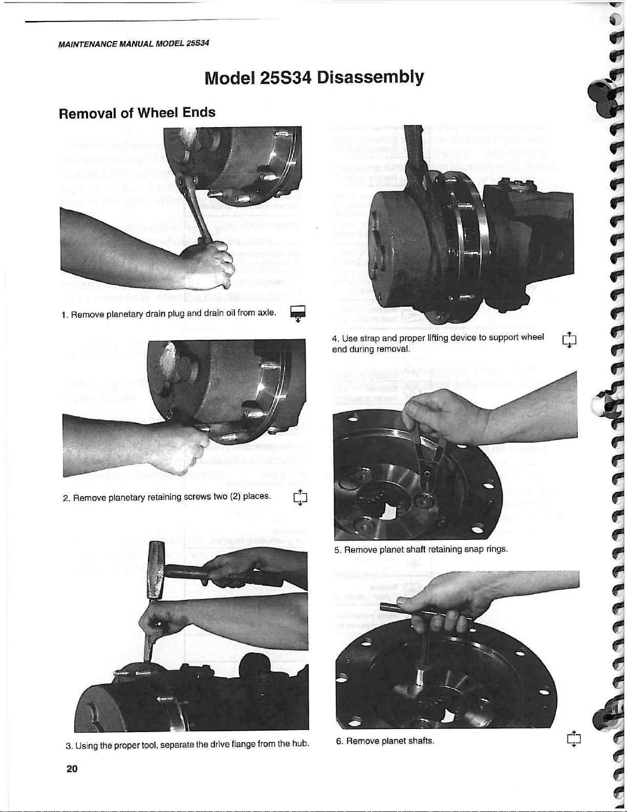
Model 25S34 Disassembly
Removal of Wheel Ends
1.
Remove planetary drain plug and drain oil from axle. =
.,.
2. Remove planetary retaining screws two
(2)
places .
4. Use strap and proper lifting device to support wheel
end
during
5.
Remove
removal
planet
.
shaft
retaining
snap
rings.
[t
]
~
3. Using the proper tool. separate the drive flange from the hub.
20
6. Remove planet shafts.

REFERENCE ONLY
7. Remove planet thrust washers.
MAINTENANCE
MANUAL
Removal of Drive Flange
MODEL
25534
AXLE
gear
.
~
B. Remove planet
cloth
to
prevent damage
9. Pla
net
gear,
assemblies. Place planet
to
gear
needle
bearing
and
teeth.
spacer
gears
removed
on
.
shop
!~
11.
12.
Drive
steer
Remove
cylinder
shims
and
clevis
O-rings
pin
from
from
steer
steer
arm.
arm.
Discard
O-rings.
21
REFERENCE ONLY
MAINTENANCE MANUAL MODEL 25S34
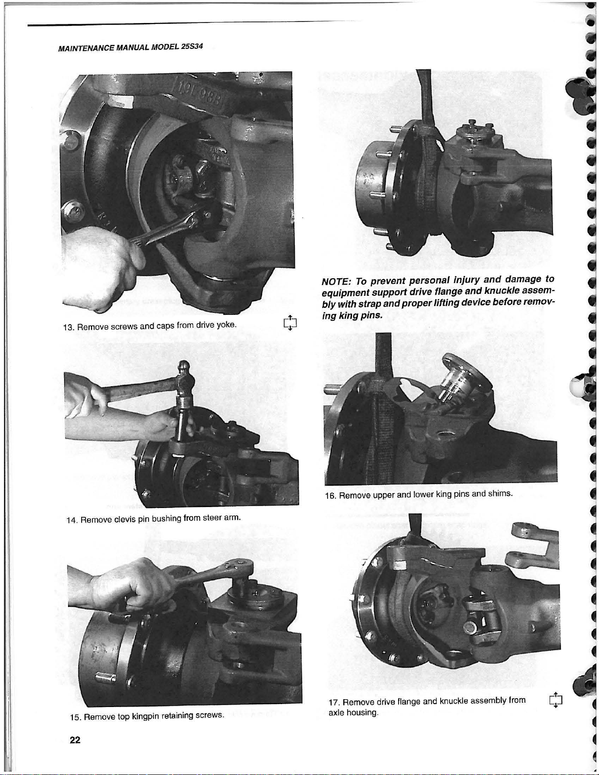
13.
14.
Remove
Remove
screws
clevis
and
pin
caps
from
bushing
from
drive
steer
yoke
arm.
NOTE:
equipment
bly
ing
.
16.
To
prevent
support
with strap
king
pins
Remove
upper
and
.
and lower
personal
drive flange
proper
lifting
king
injury
and
damage
and
knuckle assem-
device before remov-
pins and
shims
.
to
17. Remove drive flange and knuckle assembly from
axle
15.
Remove
top
kingpin
retaining
screws
.
housing
.
22
REFERENCE ONLY
rw
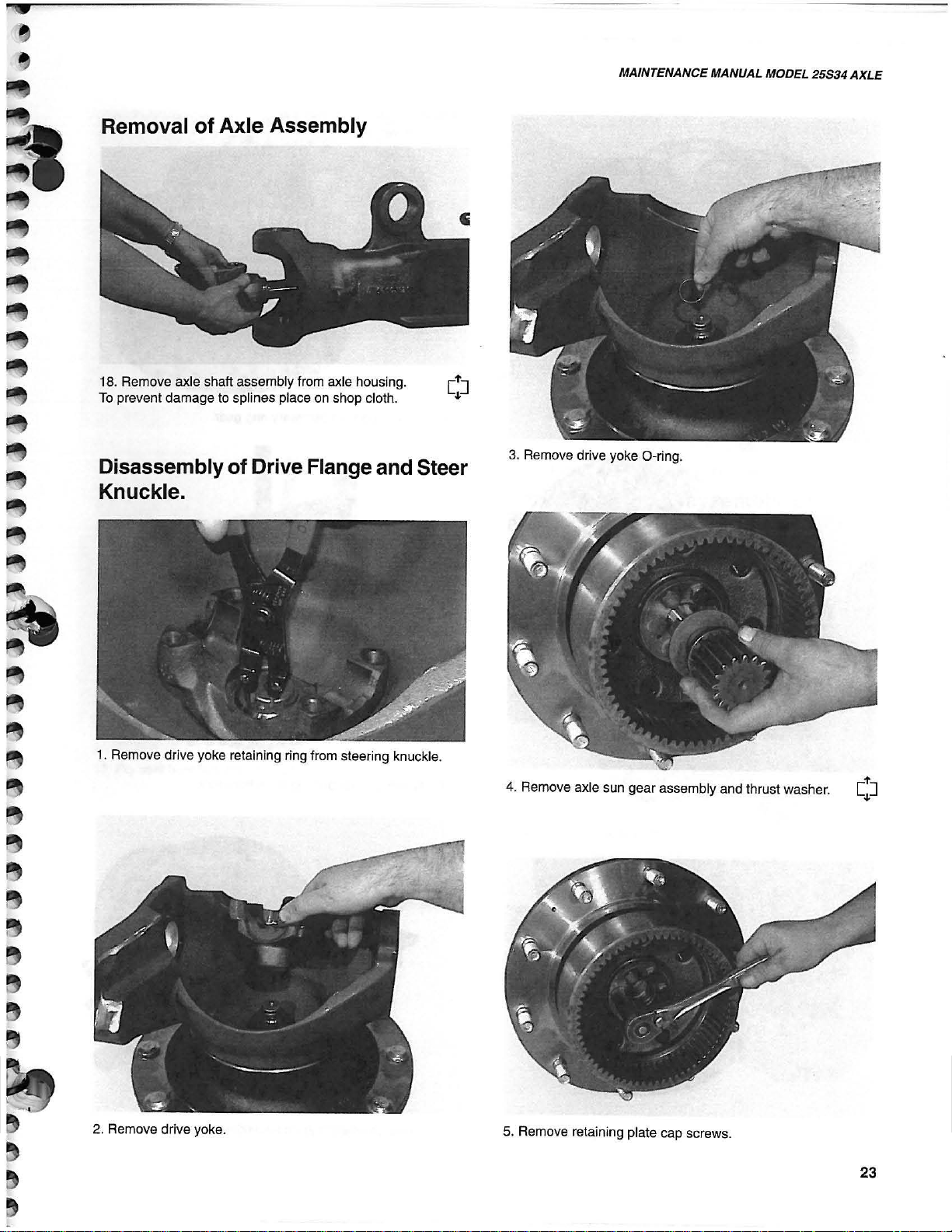
Removal
18. Remove axle shaft assembly from axle housing.
To
prevent damage to splines place
Disassembly
of
Axle Assembly
of
Drive Flange and Steer
on
shop cloth.
Knuckle.
MAINTENANCE MANUAL MODEL
3.
Remove drive yoke O-ring .
25534
AXLE
1. Remove drive yoke retaining ring from steering knuckle.
L
It
!r
/
.'
./
..
-:
/
\J
Ii
~).
.~
~
.
-
'"
2-
2.
Remove drive yoke.
4. Remove axle sun gear assembly and thrust washer.
5. Remove retaining plate cap screws.
23
REFERENCE ONLY
r.
MAINTENANCE MANUAL MODEL 25534
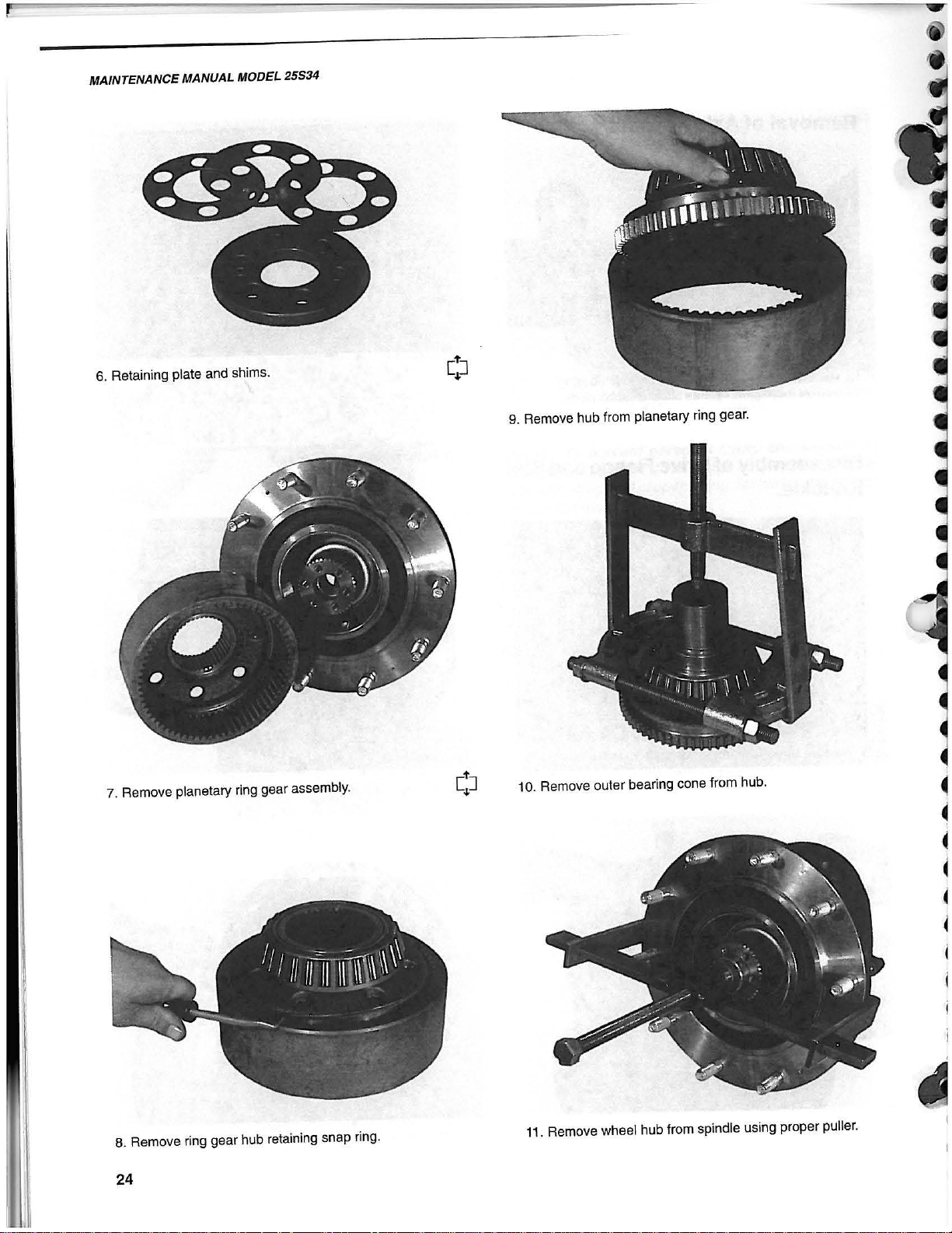
6. Retaining plate and shims.
9. Remove hub from planetary ring gear.
7. Remove planetary ring gear assembly.
8.
Remove
24
ring
gear
hub
retaining
snap
ring
Remove
11.
.
Remove wheel hub from spindle using proper puller.
outer
bearing
cone
from
hub.
10.

REFERENCE ONLY
'.
12. Hub removed from steering knuckle assembly.
15. Remove
MAINTENANCE MANUAL MODEL
inner
and
outer bearing
cups
.
25534
AXLE
Removal and Disassembly of Front
and Rear Trunnions
hub
13. Pry seal from
14.
Remove
inner
and discard.
bearing
cone
1.
Remove
2.
.
Remove
rear
rear
trunnion
trunnion
beam.
beam
thrust
washer
.
25

REFERENCE ONLY
MAINTENANCE MANUAL MODEL 25534
3.
Remove
bushing
if
damaged.
and
rear
O-rings
trunnion
for
grease
seal. Inspect trunnion
damage. Remove
and
discard
Removal and Disassembly
Cylinder
1. Loosen
jam
nut
on
socket
assembly
to remove steering arm.
of
Steer
4.
Remove
5.
Remove
and discard if damaged.
front
trunnion
front trunnion beam thrust
beam.
washer
and
seal. Inspect
2.
Remove steer cylinder retaining screws.
3.
Remove
steer
cylinder
from
carrier
housing
.
26
REFERENCE ONLY
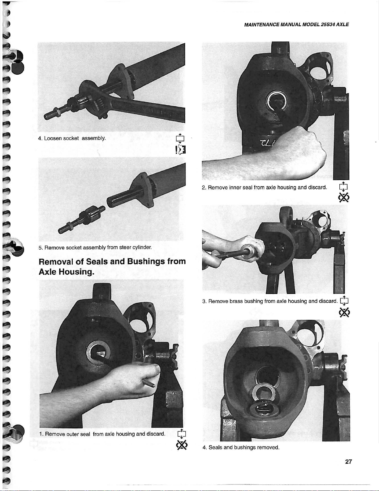
4.
Loosen
socket
assembly.
2.
Remove
MAINTENANCE
inner
seal
from
axle
MANUAL
housing
MODEL 25S34
and
discard.
AXLE
5.
Remove
socket
assembly
from
steer
cylinder.
Removal of Seals and Bushings from
Axle Housing.
3. Remove brass bushing from axle housing and discard.
C:J
~
4. Seals
and
bushings
removed
.
27
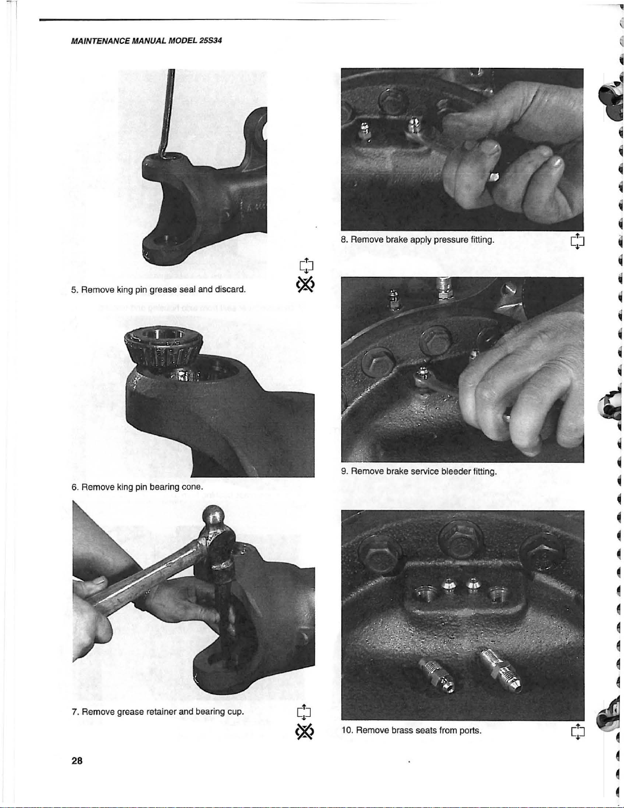
REFERENCE ONLY
MAINTENANCE MANUAL MOOEL 25534
5. Re
move
king pin grease seal and discard.
~
~
~
~
•
•
•
•
•
~
•
~
6.
Remove
king pin bearing cone.
9.
Remo
ve brake service bleeder titting.
•
•
~
7.
Remo
ve grease retainer and beari
28
ng
cup.

REFERENCE ONLY
•
Removal
NOTE: To
housing a lift
used
1.
Remove
to
support
axle
prevent
of
Axle
personal
strap
axle
housing
Housings.
injury
and
proper
housing.
retaining
and
lifting
screws.
damage to axle
device
must
be
3.
Remove
MAINTENANCE MANUAL MODEL 25534
brass
bushing
from
axle
housing
AXLE
.
4. Remove spring backing plate.
2.
Using
lifting
device
slowly
swing
axle
from
carrier
disc may fall
housing
as
brake
out.
Caution: springs may
springs,
housing
piston, shaft
away
and
be
under pressure.
5.
Remove
axle
shaft.
29

REFERENCE ONLY
PAGES 30-33 MISSING

REFERENCE ONLY
MAINTENANCE MANUAL MODEL 25534
I
.:,:
~
18. Remove oil seal, thrust washer and outer bearing
cone.
19. Remove inner and outer bearing cups.
'\ \\
21. Remove pinion mounting
Disassembly
of
Inner
Assembly.
height
shims.
Yoke and Shaft
1. Remove retaining rings.
20. Remove inner bearing cone from pinion gea r.
34
2. Place shaft assembly in fixture. Press bearing cup down until
bearing cup on bottom side can be removed. Make sure there is
clearance for bottom bearing.

REFERENCE ONLY
..
•
..
l
~
I
3.
Tum over the axle shaft assembly. Supporting the
to
drive
center yoke, press on the shaft ear
bearing
bearing cup beyond the surface of the yoke.
cup.
Make
sure
there
is
clearance
up
for
the
MAINTENANCE MANUAL MODEL 25534
AXLE
4.
Separale the axle shaft from the center yoke. Repeat the
previous
steps
separating
the
outer
yoke
from
the
cent
er
yoke.
6. U
se a dr
groove
time
until
iver
and
install
complete.
to
press
retaining
the
bearing
ring. Do this
cup
below
procedure
the
retaining
one
side
ring
at
a
5.
Installation
drive the bearing cups
ings
if
is
necessary
the rever
.
se
of
disasse
mbly
. Use a press and
10 the surface of the yoke. Grease bear-
35

REFERENCE ONLY
MAINTENANCE MANUAL MODEL 25534
Reassembly of Model 25534
Reassembly of Trunnions
1.
When
replacing
installation
2.
If
trunnion
and align hole in bushing with grease fitting hole
Reinstall grease fitting.
tool
bushing
trunnion
as
not
to
damage
is
to
bushing
be
replaced,
use
bushing
proper
.
remove
grease
in
trunnion .
[~J
!n
fitting
3. If locator pins are to be replaced, twist to remove .
Install new pins
4. tnstall new O-ring if required.
by
tapping until seated.
36

REFERENCE ONLY
Reassembly of Carrier Housing
1.
Install
new
inn
er
and
outer
bearing
cups.
[!J
3. Ins
tall
new
MAINTENANCE MANUAL MODEL
inner
beari
ng
cone
on
pinion
shaft
.
25534
AXLE
2. Install mounting distance shim(s) on pinion shaft. If new ring
and
pinion
are
to
be
installed, refer
Instructions/Chart on pages 40/41.
to
Pinion
Shim
Selection
/
(I.un
't\;,.-'
, \ . '
" .
\ ' ' ' \
4.
Press new i
5. Ins
tall
the preload spacer. Install new spacer at each overhaul.
pinion
nner
from
bearing
rear
or
cone
carrier
\
"-
'f
on
pinion
housing
~
gear
shaft.
and ins
tall
37

REFERENCE ONLY
MAINTENANCE MANUAL MODEL 25534
-
.,
Pinion Shim Selection
......
Carrier housing pinion measurement is
written inside the carrier housing.
......
The
nominal pinion measurement is 6.426
inches.
......
On
the
pilot end
numbers are listed.
......
Gearset Ld. numbers - to insure the ring
and pinion are matched. If the numbers on
new
the
use this gearset!
match to insure compatibiity.
......
Etched on the pinion will be a plus (+) sign
and a number, a minus
number
sents the amount in thousandths
added
pinion measurement to properly locate the
pinion shaft .
gearset
or
or
subtracted from the nominal
of
the pinion several
do
not match - DO NOT
The Ld. numbers MUST
(-)
sign and a
a zero (0). This number repre-
of
an inch
Using the Pinion Shim
Selection Chart
1. Locate the gage room measurement
written inside the carrier housing.
2.
Determine the pinion nominal measurement (on chart).
3. Locate the pinion adjustment number on
the pinion pilot - listed
minus
4. Scan across from the gage room measurement
column .
5. The shim thickness listed at this location
should
pinion bearing and the pinion shaft.
6. Follow the pinion reloading instructions
listed under Assembly Instruction
Notes #8 .
number, or
to the appropriate pinion adjustment
be
installed between the inner
a O.
as
a plus number,
......
(+) 2 requires a .002 thicker shim be added
between the inner bearing cone and
pinion shaft than a shaft marked O.
......
H 2 requires a .002 thinner shim be
added between the inner bearing cone and
pinion shaft than a shaft marked O.
......
The required thickness shim will be
selected from the pinion shim selection
chart listed in the specifications section.
the
38

REFERENCE ONLY
MAINTENANCE MANUAL MODEL 25534
Pinion Shim Selection Chart
AXLE
Gage Room
Measurement
& Bearing
6.468
6.469
6.47
6.471
6.472
6.473
6.474
6.475 6.426
6.476 6.426
6.477 6.426
6.478
6.479
Pinion
Nominal
6.426
6.426
6.426 0.046
6.426
6.426
6.426
Pinion Pinion Pinion Pinion Pinion Pinion
Adjustment Adjustment Adjustment Adjustment Adjustment
j-2)
Pinion Shim Pinion Shim Pinion Shim Pinion Shim Pinion Shim Pinion Shim
0.044 0.043 0.042 0.041 0.
0.045 0.044 0.043
(-1) (+0)
(+1}
0.042
(+2) (+3)
04
0.041
0.045 0.044 0.043 0.042
0.047 0.046 0.045 0.044
0.043 0.042
0.048 0.047 0.046 0.045 0.044
0.049
0.048
0.047
0.046 0.045 0.044
Adjustment
0.039
0.04
0.041
0.043
6.426 0.05 0.049 0.048 0.047 0.046 0.045
0.051 0.05 0.049 0.048 0.047 0.046
0.052 0.
051
0.053 0.052 0.
0.05 0.049 0.048
051
0.05 0.049 0.048
0.047
6.426 0.054 0.053 0.052 0.051 0.05 0.049
6.426 0.055 0.054 0.053 0.052 0.
051
0.
05
Pinion Shim Selection Chart
Pinion Pinion
Gage Room
Measurement
6.468
6.469
6.47
6.471
6.472
Nominal Adjustment Adjustment
& Bearing
(+4) (+5)
Pinion Shim Pinion Shim Pinion Shim Pinion Shim Pinion Shim
6.426 0.038 0.037 0.036 0.035 0.034
6.426 0.039 0.038 0.037 0.036 0.035
6.426 0.04 0.039 0.038 0.037 0.036 0.035
6.426 0.
6.426
041
0.042
6.473 6.426 0.043 0.042
Pinion Pinion
Adjustment
(+6)
Adjustment
0.04 0.039 0.038 0.037 0.036
0.041 0.
04
0.041
6.474 6.426 0.044 0.043 0.042 0.041
6.475
6.476 6.426
6.477 6.426
6.478
6.479 6.426
6.426 0.045 0.044 0.043 0.042 0.041
0.046 0.045 0.044 0.043
0.047 0.046 0.045 0.044 0.043
6.426 0.048 0.047 0.046 0.045
0.049 0.048 0.047
Pinion Pinion Pinion
Adjustment
(+7) (+8)
Adjustment
(+9)
Pinion Shim
0.033
0.034
0.039 0.038 0.037
0.
04
0.039
0.038
0.04 0.039
0.
04
0.042 0.041
0.042
0.044 0.043
0.046 0.045 0.044
39
REFERENCE ONLY
MAINTENANCE MANUAL MODEL 25534
..
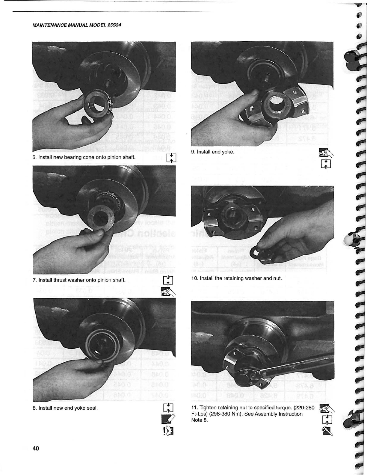
6.
Install
new
bearing
7. Install thrust washer onto pinion
cone
onto pinion
shaft.
sha~.
9. Install end yoke.
[~J
[~J
10. Install the retaining washer and nut.
8.
Install new end yoke seal.
40
. Tighten retaining nut
Ft-Lbs) (298-380 Nm). See Assembly Instruction
Nole 8.
to
specified torque. (220-280
11

REFERENCE ONLY
...
12. Using an inch/pound torque wrench take a reading
determine rolling torque. 20-40 In-Lbs. (2.25-4.5 Nm).
to
MAINTENANCE MANUAL MODEL 25534
15. Side gears and thrust washer installed.
AXLE
13.
Press
new
bearing
14. Install thrust washers,
into
differential
cones
case.
onto
differential
top
and bottom side
case.
gear
16. Install both pinion gears and thrust washer then
rotate
to
align
shaft
bore
with
gears
and
washers.
17. Install pinion gear shaft aligning hole
with roll pin hole in differential case.
in
shaft
41

REFERENCE ONLY
MAINTENANCE MANUAL MODEL 25534
-
...,
18. With holes aligned, drive roll pin into shaft.
19.
Clean
surfaces.
retaining
differential
Position
bolts.
ring
case
gear
and
and
ring
install
gear
mounting
new
21. Assemble bearing cups
cones
.
22.
Install
differential
install retaining caps, torque
(101-122 Nm).
case
on
differential bearing
into
carrier
housing
to
75-90
Ft.
Lbs.
and
[!J
E8
20. Torque bolts to 90-100
42
Ft.
Lbs. (122-135 Nm).
23. Install adjusting rings.
[!J
REFERENCE ONLY
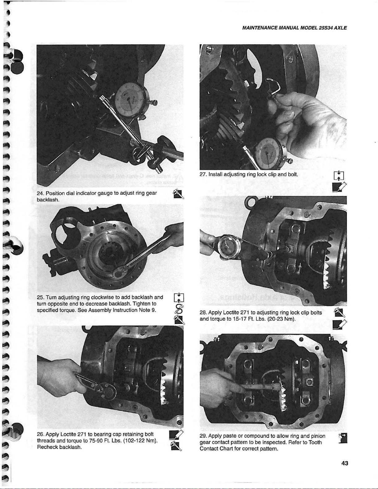
24. Position dial indicator gauge to adjust ring gear
backlash.
MAINTENANCE MANUAL MODEL 25534
27. Install adjusting ring lock clip and bolt.
AXLE
to
25. Turn adjusting ring clockwise
turn opposite end to decrease backlash . Tighten to
specified torque. See Assembly Instruction Note 9.
26. Apply Locme
threads and torque to 75Recheck backlash.
271
to bearing cap retaining bolt
90
add backlash and
Fl.
Lbs. (102-122 Nm).
28. Apply Loctite
and torque to 15-17 Ft.
29. Apply paste or compound to allow ring and pinion
gear
contact
Contact Chart for correct pattern.
271
pattern
to
adjusting ring lock clip bolts
Lb
s. (20-23 Nm).
to
be
inspected.
Refer
to
Toot
h
43
REFERENCE ONLY
MAINTENANCE MANUAL MODEL 25534
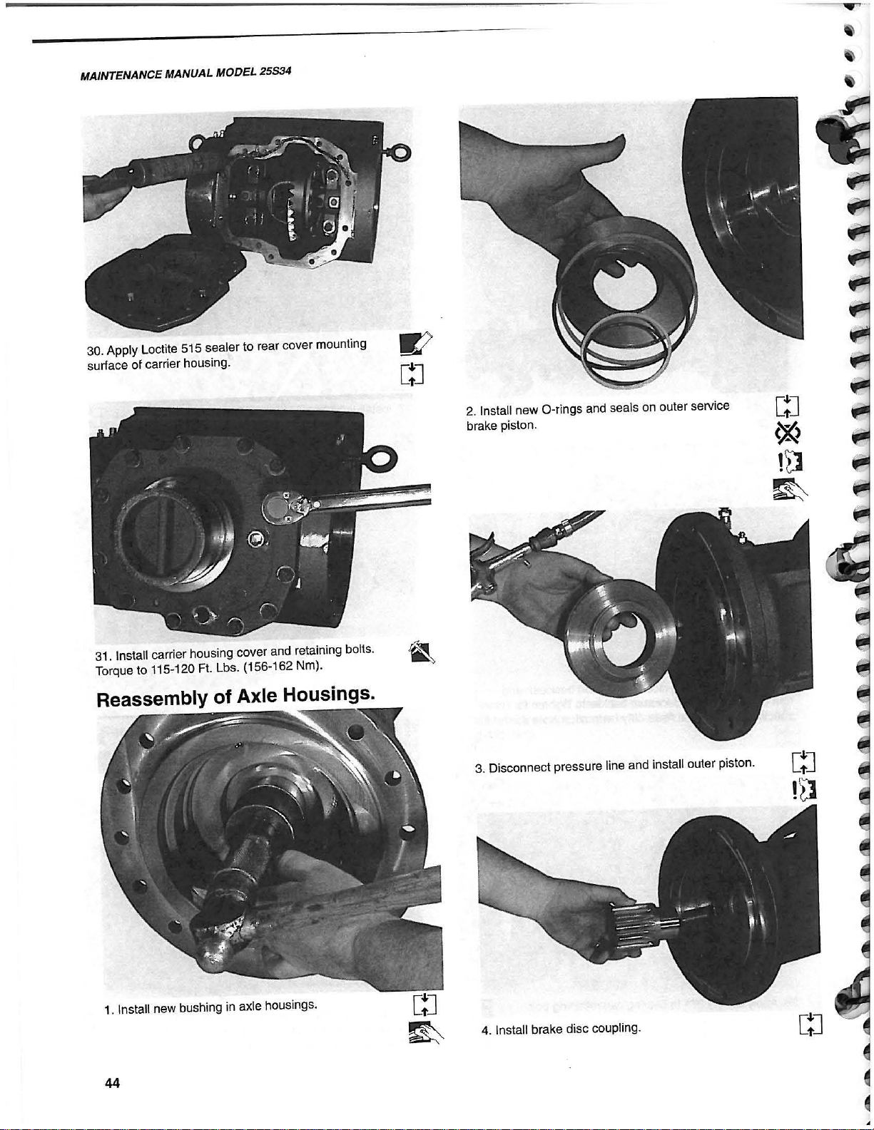
30. Apply Loctite 515 sealer to rear cover mounting
surrace
of
carrier
housing.
2.
Install
brake
new
piston.
O-rings
and
seals
on
outer
service
31.
Install
carrier
housing
Torque to 115-120 Ft. Lbs. (156-162 Nm).
Reassembly
1. Install new bushing in axle housings.
cover
and
retaining
of
Axle Housings.
bolts
.
3. Di
sconnect
pressure
line
and
install
outer
piston.
[~J
!~
4. Install brake disc coupling.
44

REFERENCE ONLY
•
,..
---
"
,j )
~
~
jI!It
~
~
.
5. Install brake disc
disc and alternating with (4) four friction disc.
in
axle housing starting with a steel
MAINTENANCE MANUAL MODEL
8. Install parking brake springs.
25534
AXLE
6.
Install
new
Q-rings
brake
piston.
7. Install inner parking brake piston.
and
seals
on
inner
parking
9. Install new O-ring to axle housing.
10. Install axle shaft into axle housing. Be sure to
install
on
correct
side
.
GJ
.&
45

REFERENCE ONLY
I 1
MAINTENANCE MANUAL MODEL
11.
Install parking brake spring backing plate
carrier
housing
.
25834
in
13. Install new axle housing bolts and torque to
110-120
Ft.
Lbs. (199-162 Nm).
12. Using a lifting device balance the axle housing
and
install
into
carrier
housing
46
.

REFERENCE ONLY
MAINTENANCE MANUAL MOOEL
25534
AXLE
16. Torque fittings
to
84-120 In. Lbs. (9.5-13.5 Nm).
19. Apply grease to bearing cone and cup prior to installation.
20. Using proper tool, install grease seal being careful
not
to
damage seal.
!t3
new
bushing and seal into end of
.
47
18. Using proper tool, drive bearing cup down until
seated properly.
21. Install
axle
housing

REFERENCE ONLY
MAINTENANCE MANUAL
Reassembly of Wheel Ends .
MODEL
25S34
"
1.
Install new inner and outer bearing cups and
cones
in hub
.
.....
m""!1
! I
I
. I
. 1
'.
II
Ilnnrlli
4.
Press
new
outer
bearing
bearing may ease installation. (Do not exceed 275 .
degrees). See Assembly Instruction Note 15 (pg. 15).
-
-\
! 1
onto
ring
~
\
\
~\
gear
hub
. Heating
[!J
,.
!n
2.
Install
new
hub
seal
using
proper
3. Assemble wheel end onto knuckle.
48
driver
.
5. Position ring gear hub into ring gear.
6. Install hub retaining ring into gear assembly.
[!J
[!J

REFERENCE ONLY
,
•
•
l
!if
'"
pit
'"
!If
~
!it
~
~
~
6. Position planetary ring gear, knuckle and hub.
MAINTENANCE MANUAL MODEL 25534
9. Install retaining plate cap screws with Loctite
and tighten.
AXLE
271
7. Assemble ring gear
8. Install
Assembly Instruction Note
shims
on
and bearing preload retainer plate. See
splines of knuckle.
11
.
10. Check rolling torque on wheel after torquing bolts •
to 115/120 Ft. Lbs. (156-162 Nm).
11.
Press a new
if
required.
thrust
washer
on
sun
gear
shaft
49
l
REFERENCE ONLY
MAINTENANCE MANUAL
MODEL
25534
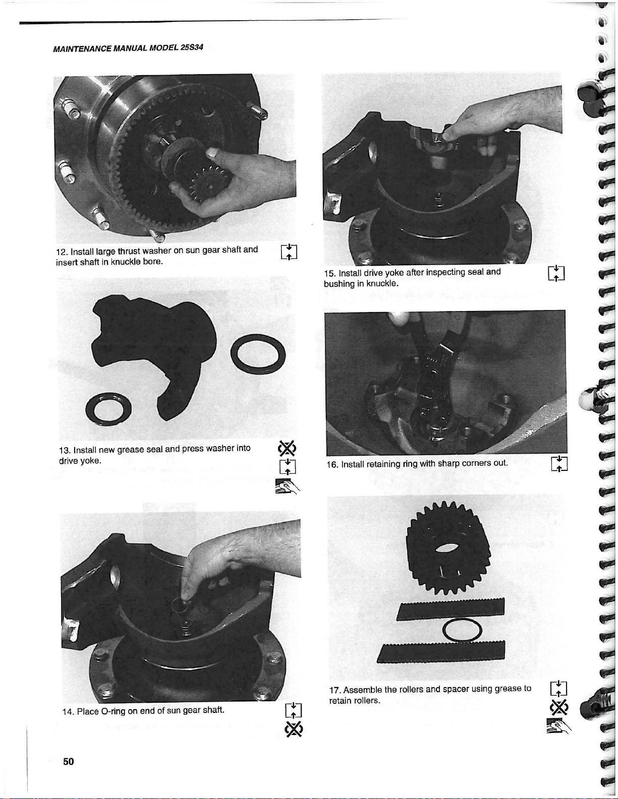
12. Install large thrust washer on sun gear shaft and
insert shaft in knuckle bore.
o
o
13.
Install
new
grease
seal
and
press
washer
drive yoke.
into
Ct"'J
15. Install drive yoke after inspecting seal and
bushing in knuckle.
[!J
to
14. Place O-ring on end of sun gear shaft.
50
17. Assemble the rollers and spacer using grease
retain
rollers
.
REFERENCE ONLY
•
MAINTENANCE MANUAL MODEL
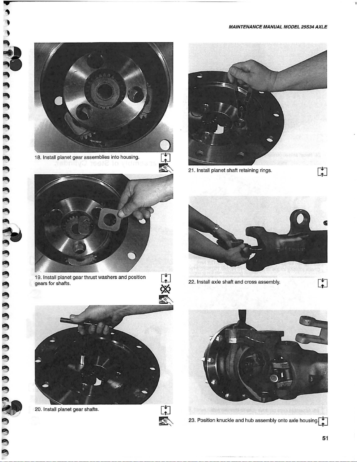
21
. Inslall planet shaft retaining rings.
25534
AXLE
19. Install planet gear thrust washers and position
gears for shafts.
20. Install planet gear shafts.
22. Install axle shaft and cross assembly.
23. Position knuckle and hub assembly onto axle housi
ng[!J
51

REFERENCE ONLY
MAINTENANCE MANUAL MODEL
25534
27.
lighten
55-60
yoke cap bolts
Ft.
Ibs. (74.5-81.3 Nm).
to
specified torque.
24. Install shims,
lighten
25.
Check rotating torque at kingpin 8-15 Ft.-Ibs. (10.8-20.3 Nm).
on
top and bottom kingpins.
kingpin bolts to 80-90 Ft.-Ibs. (108-122 Nm).
Reassembly of Steer Cylinder.
1 . Assemble socket assembly
271
Apply Loctite
(260-280 Nm).
and torque to 192-207
to
steer cylinder.
Ft.
Lbs.
2. Install steer cylinder into axle housing cradle.
26. Assemble caps
shatt assembly.
on
drive yoke
to
connect axle
[!J
•
52

REFERENCE ONLY
M
,
~
,.
~
~
~
~
r-
r.-
..
3. Install steer cylinder retaining bolts and tighten to
specified torque.
80-90 Ft.-Lbs. (108-122 Nm).
6.
Position
MAINTENANCE MANUAL MODEL 25534
steer
arm,
shims
and
O-ring
on
knuckle
AXLE
.
GJ
4. Install steering arm and torque to 121
(299 Nm).
Ft.
Lbs.
7.
Dri
ve
clevis
pin
through
aligning roll pin retaining holes.
8. Drive
roll
pin into
bore
clevis pin.
of
arm
and
knuckle,
GJ
GJ
,.
53

REFERENCE ONLY
-------
_
.-
---
MAINTENANCE MANUAL MODEL 25534
9. Apply loctite 515 on face
flange assembly. See Assembly Instruction Note 12.
of
hub and install drive
2.
Install
rear
trunnion
assembly
onto
carrier
housing.
. ;
[!J
10. Install planetary retaining bolt two (2) places. Torque
to
40-45 Ft.-Lbs. (54-61 Nm). See Assembly Instruction t
Note 12.
Installation
of
Front and Rear
Trunnions.
1.
Install
V-ring
seal
and
thrust
mount.
Grooves
are
to
face
washer
out.
on
rear
trunion
C"'J
.,
3. Install front trunnion V-ring and thrust washer.
Grooves to face out.
4.
Install
front
trunnion
housing.
mount
assembly
on
carrier
GJ
54

REFERENCE ONLY
PW
!WI
:&
,.
•
•
.,
.,
.,
;.e
;.e
;.e
•
~
~
,.,
Bleeding the Brake System
1.
Fill the master cylinder reservoir with
approved fluid before starting the bleeding
operation. Keep the reservoir at least half
full of fluid at all times during the bleeding
operation. (Note:
drained at any time during the bleeding
operation, air will enter the system and
rebleeding will be necessary).
2.
Start the brake bleeding operation at the
brake head with the
master cylinder.
3.
While applying pressure from the pressure
bleeder tank (or when mechanically bleeding, depress the brake pedal) open the
bleeder screw and observe the flow of
fluid. The pressure will move the fluid
through the system and out the open
bleeder screw carrying with it any air
(evidenced by bubbles
that was trapped in the line and cylinder.
if
the master cylinder
longest
line to the
in
the flow of fluid)
is
MAINTENANCE MANUAL MODEL 25S34
4. Close the bleeder screw when the flow of
fluid appears free
solid. Reopen screw momentarily, then
tighten.
NOTE: Fluid drained during the bleeding
operation shall not be re-used
because of possible contamination
during the bleeding operation. The
fluid level
should be replenished after each
bleeding sequence.
5.
Repeat procedure for each remaining
brake. Work progressively from the brake
with the
longest
of
bubbles and flows
in
the master cylinder
line.
AXLE
.-.
.
..
..
..
..
..
..
..
..
..
j
~
~
~
~
NOTE: The bleeder screw must remain
closed until the brake pedal has
been fully depressed to prevent air
from entering the system. After
bleeding, the bleeder screw must
be closed before the pedal
released .
is
55

REFERENCE ONLY
MAINTENANCE MANUAL MOOEL 25534
NOTES
56

REFERENCE ONLY
~
I
~
I
~
,
~
~
~
~
~
~
~
~
~
~
~
~
~
~
~
~
~
~
~
~
~
~

REFERENCE ONLY
 Loading...