

Genie AWP Super Series, IWP Super Series Service Manual

Service Manual
Serial Number Range
AWP Super Series
from 3896-101
99999
21194
87799
87800
IWP Super Series
from 4096-101
4413
4205
11999
from IWPG-12000
Part No. 38139
Rev B11
September 2016
to 3801-
from AWP02-
to AWP16Gfrom AWPG-
to 4001from IWP02to IWP16G-

Service Manual September 2016
Introduction
Introducti on Introducti on
Important Inform ation
Important
Read, understand and obey the safety rules and
operating instructions in the appropriate Operator's
Manual on your machine before attempting any
maintenance procedure.
This manual provides detailed scheduled
maintenance information for the machine owner
and user. It also provides troubleshooting and
repair procedures for qualified service
professionals.
Basic mechanical, hydraulic and electrical skills are
required to perform most procedures. However,
several procedures require specialized skills, tools,
lifting equipment and a suitable workshop. In these
instances, we strongly recommend that
maintenance and repair be performed at an
authorized Genie dealer service center.
Technical Publications
Genie has endeavored to deliver the highest
degree of accuracy possible. However, continuous
improvement of our products is a Genie policy.
Therefore, product specifications are subject to
change without notice.
Readers are encouraged to notify Genie of errors
and send in suggestions for improvement. All
communications will be carefully considered for
future printings of this and all other manuals.
Contact Us:
Internet: www.genielift.com
E-mail: awp.techpub@terex.com
Find a Manual for this Model
Compliance
Machine Classification
Group A/Type 1 as defined by ISO 16368
Machine Design Life
Unrestricted with proper operation, inspection and
scheduled maintenance.
Go to http://www.genielift.com
Use the links to locate Service Manuals,
Maintenance Manuals, Service and Repair
Manuals, Parts Manuals and Operator's Manuals.
Copyright © 1996 by Terex Corporation
38139 Rev B, December 2001
First Edition, Second Printing
'Genie', 'AWP' and 'IWP' are registered trademarks of Terex
South Dakota. in the U.S.A. and many other countries. “Super
Series” is a trademark of Terex South Dakota.
ii AWP Super Series • IWP Super Series Part No. 38139
September 2016 Service Manual
Introduction
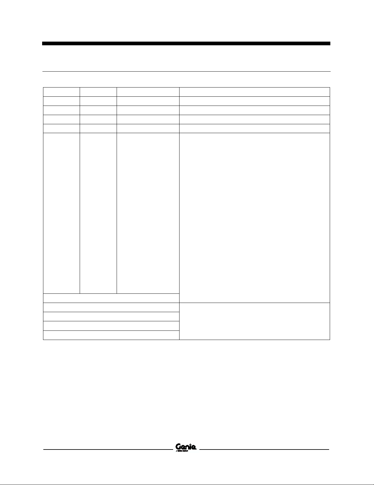
Revision History
Revision History
Revision Date Section Procedure / Page / Description
B8 5/2015 Maintenance Removed C-6
B9 8/2016 Repair 5-4
B10 9/2016 Introduction Serial Number Legend
B11 9/2016 Schematics Page 166
Reference Examples:
Section – Maintenance, B-3
Section – Repair Procedure, 4-2
Section – Fault Codes, All charts
Section – Schematics, Legends and schematics
Electronic Version
Click on any content or procedure in the Table of Contents to view
the update.
Part No. 38139 AWP Super Series • IWP Super Series iii
Service Manual September 2016
Introduction
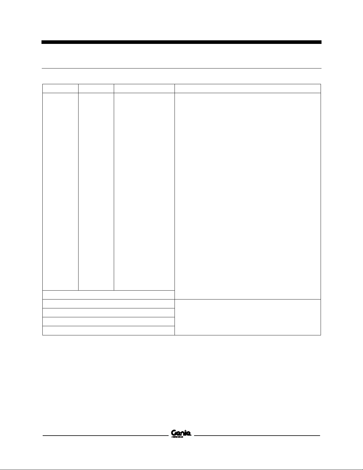
Revision History (continued)
Revision Date Section Procedure / Page / Description
Reference Examples:
Section – Maintenance, B-3
Section – Repair Procedure, 4-2
Section – Fault Codes, All charts
Section – Schematics, Legends and schematics
Electronic Version
Click on any content or procedure in the Table of Contents to view
the update.
iv AWP Super Series • IWP Super Series Part No. 38139
September 2016 Service Manual
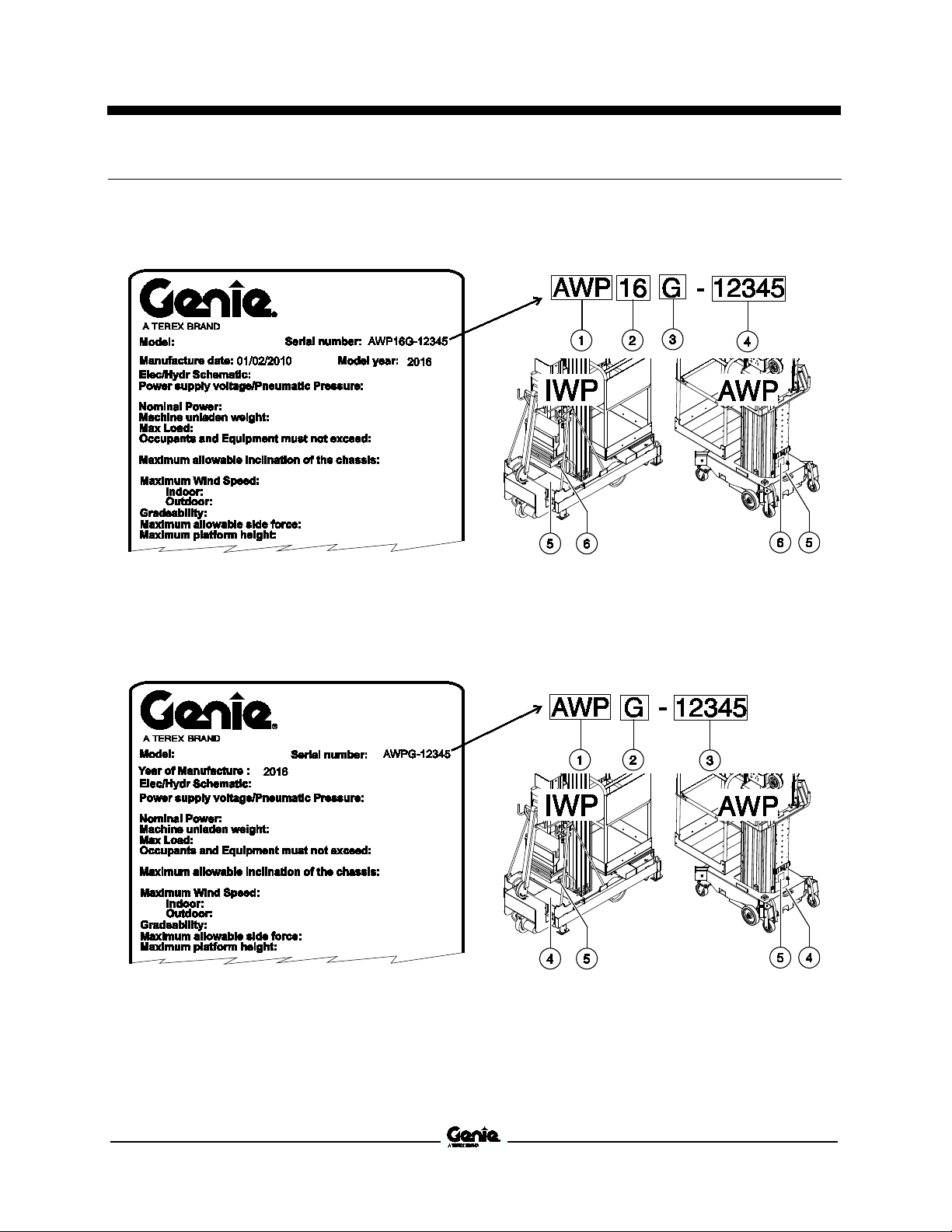
To August 31,
From September 1, 2016
Introduction
Serial Number Legend
2016
1 Model
2 Model year
3 Facility code
1 Sequence number
2 Serial number (stamped on chassis)
3 Serial label
1 Model
2 Facility code
3 Sequence number
1 Serial number (stamped on chassis)
2 Serial label
Part No. 38139 AWP Super Series • IWP Super Series v

Service Manual September 2016
Safety Rules
Section 1 Safety Rules
General Saf ety R ules
Danger
Failure to obey the instructions and safety rules in
this manual and the appropriate Operator's Manual
on your machine will result in death or serious
injury.
Many of the hazards identified in the operator's
manual are also safety hazards when maintenance
and repair procedures are performed.
Do Not Perform Maintenance
Unless:
You are trained and qualified to perform
maintenance on this machine.
You read, understand and obey:
• manufacturer's instructions and safety rules
• employer's safety rules and worksite
regulations
• applicable governmental regulations
You have the appropriate tools, lifting
equipment and a suitable workshop.
vi AWP Super Series • IWP Super Series Part No. 38139
September 2016 Service Manual
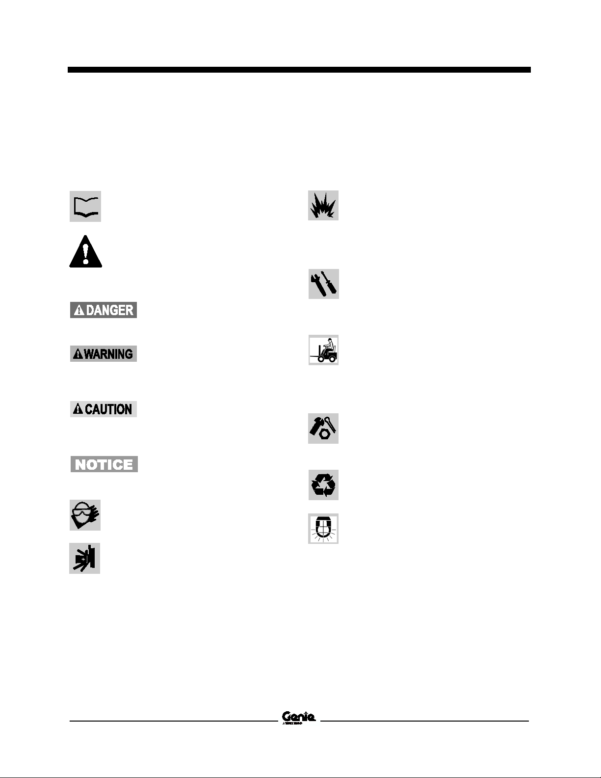
Read each procedure thoroughly. This
manual and the decals on the machine,
use signal words to identify the following:
Safety alert symbol
t
personnel to potential personal
injury hazards. Obey all safety
messages that follow this symbol
to avoid possible injury or death.
Indicates a imminently hazardous
situation which, if not avoided, will
result in death or serious injury.
Indicates
situation which, if not avoided,
could result in death or serious
injury.
Indicates a potentially hazardous
situation which, if not avoided,
may cause minor or moderate
injury.
Indicates a potentially hazardous
situation which
may result in property damage.
Be sure to wear protective eye wear and
other protective clothing if the situation
warrants it.
Be aware of potential crushing hazards
such as moving parts, free swinging or
unsecured components when
placing loads. Always wear approved
steel
Be sure to keep sparks, flames and
lighted tobacco away from flammable and
combustible materials like battery gases
and engine fuels. Always have an
approved fire extinguisher within easy
reach.
Be sure that all tools and working areas
are prop
use. Keep work surfaces clean and free of
debris that could get into machine
components and cause damage.
Be sure any forklift, overhead crane or
other lifting or supporting device is fully
capable of supporting and stabili
weight to be lifted. Use only chains or
straps that are in good condition and of
ample capacity.
Be sure that fasteners intended for one
time use (i.e., cotter pins and self
nuts) are not reused. These components
may fail if they are us
Be sure to properly dispose of old oil or
other fluids. Use an approved container.
Please be environmentally safe.
Be sure that your workshop or work area
is properly ventilated and well lit.
Safety Rules
Personal Safety
Any person working on or around a machine must
be aware of all known safety hazards. Personal
safety and the continued safe operation of the
machine should be your top priority.
—used to aler
a potentially hazardous
, if not avoided,
Workplace Safety
Any person working on or around a machine must
be aware of all known safety hazards. Personal
safety and the continued safe operation of the
machine should be your top priority.
erly maintained and ready for
ed a second time.
zing the
-locking
-toed shoes.
Part No. 38139 AWP Super Series • IWP Super Series vii
lifting or

September 2016
Table of Contents
Introduction Introduction .......................................................................................................... ii
Important Information .............................................................................................. ii
Find a Manual for this Model ................................................................................... ii
Revision History ..................................................................................................... iii
Serial Number Legend ........................................................................................... v
Section 1 Safety Rules ......................................................................................................... vi
General Safety Rules ............................................................................................. vi
Section 2 Specifications ..................................................................................................... 17
AWP-15S, 20S and 25S Specifications ............................................................... 17
AWP30S, 36S and 40S Specifications ................................................................ 18
AWP Narrow Base Specifications ........................................................................ 19
AWP Rough Terrain Base Specifications ............................................................ 20
IWP Specifications ............................................................................................... 21
AWP/IWP Performance and Hydraulic Specifications ......................................... 22
Hydraulic Hose and Fitting Torque Specifications ............................................... 23
Torque Procedure ................................................................................................ 24
SAE and Metric Fasteners Torque Charts ........................................................... 26
viii AWP Super Series • IWP Super Series Part No. 38139

September 2016
Table of Contents
Section 3 Scheduled Maintenance Procedures ............................................................... 27
Introduction ........................................................................................................... 27
Pre-Delivery Preparation Report .......................................................................... 31
Maintenance Inspection Report............................................................................ 33
Checklist A Procedures ..................................................................................... 35
A-1 Inspect the Manuals and Decals.................................................................... 35
A-2 Perform Pre-operation Inspection .................................................................. 36
A-3 Perform Function Tests ................................................................................. 36
A-4 Inspect for Damage and Loose or Missing Parts........................................... 37
A-5 Check for Hydraulic Leaks ............................................................................. 38
A-6 Check the Hydraulic Oil Level ........................................................................ 38
A-7 Test the Base Operation - IWPS Models ....................................................... 39
A-8 Test the Auxiliary Platform Lowering Operation ............................................ 39
A-9 Test the Manual Platform Lowering Operation .............................................. 40
A-10 Inspect the Columns for Damage ................................................................ 40
A-11 Check the Sequencing Cables .................................................................... 41
A-12 Check the Interlock System for Proper Operation ....................................... 41
A-13 Test the Power and Function Controls ........................................................ 43
A-14 Inspect the Lifting Chains and Idler Wheels ................................................ 43
A-15 Inspect the Breather Cap ............................................................................. 44
A-16 Check the Tire Pressure -
AWPS Models with Rough Terrain Base Option .......................................... 45
A-17 Check the Air Supply Lubricator Oil Level - Air Models ............................... 45
A-18 Check the Air Supply Lubricator Drip Rate - Air Models ............................. 46
A-19 Check the Air Filter/Regulator Canister - Air Models ................................... 46
Part No. 38139 AWP Super Series • IWP Super Series ix

September 2016
Table of Contents
Checklist B Procedures ..................................................................................... 47
B-1 Inspect the Battery ........................................................................................ 47
B-2 Inspect the Electrical Wiring .......................................................................... 47
B-3 Inspect All Welds ........................................................................................... 48
B-4 Test the Tilt-back Operation (if equipped) ..................................................... 48
B-5 Check the Lifting Chain Adjustment .............................................................. 50
B-6 Clean and Lubricate the Columns ................................................................. 51
B-7 Test the Lifting Capacity ................................................................................ 51
B-8 Adjust the Sequencing Cables ...................................................................... 52
B-9 Inspect for Proper Outrigger Length - AWPS Models ................................... 53
B-10 Inspect and Lubricate the Outrigger Leveling Jack Footpads -
AWPS Models ............................................................................................. 55
B-11 Test the Level Sensing Operation - IWPS Models ...................................... 55
B-12 Check the Chain Adjustment, IWP-20S Models with Outreach Option....... 56
Checklist C Procedures ..................................................................................... 57
C-1 Inspect and Lubricate the Casters and Wheels ............................................ 57
C-2 Inspect the Mast Assembly for Wear ............................................................ 57
C-3 Inspect and Lubricate the Lifting Chains ....................................................... 59
C-4 Replace the Hydraulic Oil .............................................................................. 59
C-5 Replace the Auxiliary Platform Lowering Batteries ....................................... 61
x AWP Super Series • IWP Super Series Part No. 38139

September 2016
Table of Contents
Section 4 Repair Procedures ............................................................................................. 63
Introduction ........................................................................................................... 63
Base Assembly ................................................................................................... 65
1-1 Interlocks ........................................................................................................ 65
1-2 Base Components IWPS Models ................................................................... 66
1-3 Foot Pump Manifold Components - IWPS Models (to SN IWP09-8269) ....... 70
1-4 Foot Pump Manifold Components -
IWPS Models (from SN IWP09-8270) .......................................................... 71
1-5 Power Wheel Assist Manifold Components -
IWPS Models (to SN 4097-990) ................................................................... 72
1-6 Power Wheel Assist Manifold Components -
IWPS Models (from SN 4097-997 to 4099-2532) ......................................... 73
1-7 Power Wheel Assist Manifold Components -
IWPS Models (from SN 4099-2533) ............................................................. 74
Ground Controls ................................................................................................. 75
2-1 How to Test the Transformer - AC Models .................................................... 75
2-2 How to Test the AC Contactor - AC Models .................................................. 76
Hydraulic Power Unit ......................................................................................... 77
3-1 Hydraulic Power Unit - AC Models
(to SN AWP03-27389 and IWP03-5150) ...................................................... 77
3-2 Hydraulic Power Unit - AC Models
(from SN AWP03-27390 to AWP08-60145) ................................................. 78
3-3 Hydraulic Power Unit - DC Models
(to SN AWP03-27401 and IWP03-5122) ...................................................... 80
3-4 Hydraulic Power Unit Components - Air Powered Models
(to SN AWP04-27778) .................................................................................. 82
3-5 Hydraulic Power Unit ...................................................................................... 85
3-6 Hydraulic Pump .............................................................................................. 87
3-7 Valve Adjustment ........................................................................................... 87
3-8 How to Test the Motor Start Solenoid - DC Models ....................................... 88
Part No. 38139 AWP Super Series • IWP Super Series xi

September 2016
Table of Contents
Power Pack ......................................................................................................... 89
4-1 Power Pack .................................................................................................... 89
Mast Components .............................................................................................. 90
Mast Components ................................................................................................ 90
5-1 Lift Cylinder .................................................................................................... 91
5-2 Mast Assembly .............................................................................................. 92
5-3 Glide Pads ..................................................................................................... 97
5-4 Lifting Chains ................................................................................................. 98
Tilt-back Frame, AWP-36S and 40S Models .................................................. 101
6-1 Tilt-back Frame ............................................................................................ 101
Platform ............................................................................................................. 103
7-1 Platforms ...................................................................................................... 103
7-2 Platform Control Box .................................................................................... 104
7-3 Platform Outreach Chain ............................................................................. 105
xii AWP Super Series • IWP Super Series Part No. 38139

September 2016
Table of Contents
Section 5 Schematics ........................................................................................................ 107
Introduction ......................................................................................................... 107
Electrical Component and Wire Color Legends ................................................. 108
Electrical Symbol Legend ................................................................................... 110
Hydraulic Symbols Legend ................................................................................. 111
Electrical Schematics - AWP Models ............................................................. 113
Electrical Schematic - AWP Super Series DC Models
(from SN 3896-101 to 3896-300)................................................................ 114
Electrical Schematic - AWP Super Series DC Models
(from SN 3896-301 to 3896-430)................................................................ 115
Electrical Schematic - AWP Super Series DC Models
( from SN 3896-431 to AWP07-54898) ...................................................... 118
Electrical Schematic - AWP Super Series DC Models with Standard Base
(from SN AWP07-54899) ............................................................................ 119
Electrical Schematic - AWP Super Series DC Models with Narrow Base
(from SN AWP07-54899) ............................................................................ 122
Electrical Schematic - AWP Super Series DC CE Models
(from SN 3896-432 to AWP07-54898) ....................................................... 123
Electrical Schematic - AWP Super Series DC CE Models with Standard Base
(from SN AWP07-54899) ............................................................................ 126
Electrical Schematic - AWP Super Series DC CE Models with Narrow Base
(from SN AWP07-54899) ............................................................................ 127
Electrical Schematic - AWP Super Series DC TUV Models
(from SN 3896-431) .................................................................................... 130
Part No. 38139 AWP Super Series • IWP Super Series xiii

September 2016
Table of Contents
Electrical Schematic - AWP Super Series AC Models
(from SN 3896-103 to 3896-303) ............................................................... 131
Electrical Schematic - AWP Super Series AC Models
(from SN 3896-304 to 3896-450) ............................................................... 134
Electrical Schematic - AWP Super Series AC Models
(from SN 3896-451 to AWP07-54898) ....................................................... 135
Electrical Schematic - AWP Super Series AC Models with Standard Base
(from SN AWP07-54899 to AWP07-57594) ............................................... 138
Electrical Schematic - AWP Super Series AC Models with Narrow Base
(from SN AWP07-54899 to AWP-57594) ................................................... 139
Electrical Schematic - AWP Super Series AC Models with Standard Base
(from SN AWP07-57595) ........................................................................... 142
Electrical Schematic - AWP Super Series AC Models with Narrow Base
(from SN AWP07-57595) ........................................................................... 143
Electrical Schematic - AWP Super Series AC CE Models
(from SN 3896-451 to AWP07-54898) ....................................................... 146
Electrical Schematic - AWP Super Series AC CE Models with Standard Base
(from SN AWP07-54899 to AWP07-57594) ............................................... 147
Electrical Schematic - AWP Super Series AC CE Models with Narrow Base
(from SN AWP07-54899 to AWP07-57594) ............................................... 150
Electrical Schematic - AWP Super Series AC CE Models with Standard Base
(from SN AWP-57595) ............................................................................... 151
Electrical Schematic - AWP Super Series AC CE Models with Narrow Base
(from SN AWP07-57595) ........................................................................... 154
Electrical Schematic - AWP Super Series AC TUV Models
(from SN 3896-461) ................................................................................... 155
xiv AWP Super Series • IWP Super Series Part No. 38139

September 2016
Table of Contents
Electrical Schematics - IWP Models ............................................................... 157
Electrical Schematic - IWP Super Series DC Models
(from SN 4096-101 to 4096-287)................................................................ 158
Electrical Schematic - IWP Super Series DC Models
(from SN 4096-288 to 4096-341)................................................................ 159
Electrical Schematic - IWP Super Series DC Models
(from SN 4096-342 to IWP07-7065) ........................................................... 162
Electrical Schematic - IWP Super Series DC Models
(from SN IWP07-7066) to IWP15-9621 ...................................................... 163
Electrical Schematic - IWP Super Series DC Models
(from SN 4096-342 to IWP07-7065) ........................................................... 166
Electrical Schematic - IWP Super Series DC Models with Power Assist ........... 167
Electrical Schematic - IWP Super Series DC Models with Power Assist
(Directional Valve Coils Powering Function Manifold)................................ 170
Electrical Schematic - IWP Super Series DC TUV Models ................................ 171
Electrical Schematic - IWP Super Series DC TUV Models with Outreach......... 174
Electrical Schematic - IWP Super Series DC TUV
Models with Power Assist ........................................................................... 175
Electrical Schematic - IWP Super Series DC TUV
Models with Power Assist and Outreach .................................................... 178
Electrical Schematic - IWP Super Series DC TUV Models with Power Assist
(Directional Valve Coils Powering Function Manifold)................................ 179
Part No. 38139 AWP Super Series • IWP Super Series xv

September 2016
Table of Contents
Electrical Schematic - IWP Super Series AC Models
(from SN 4096-105 to 4096-285) ............................................................... 182
Electrical Schematic - IWP Super Series AC Models
(from SN 4096-286 to 4096-355) ............................................................... 183
Electrical Schematic - IWP Super Series AC Models
(from SN 4096-356 to IWP07-7065) .......................................................... 186
Electrical Schematic - IWP Super Series AC Models
(from SN IWP07-7066 to IWP07-57594) ................................................... 187
Electrical Schematic - IWP Super Series AC Models
(from SN IWP07-57595) ............................................................................. 190
Electrical Schematic - IWP Super Series AC TUV Models
(With Base Mounted Junction Box) ............................................................ 191
Electrical Schematic - IWP Super Series AC TUV Models
(Without Base Mounted Junction Box) ....................................................... 194
Electrical Schematic - IWP Super Series AC TUV Models with Outreach ........ 195
Hydraulic Schematics - All Models ................................................................ 197
Hydraulic Schematic - AWP Super Series Models ............................................ 198
Hydraulic/Pneumatic Schematic - AWP Super Series Models .......................... 199
Hydraulic Schematic - IWP Super Series Models without Power Assist ........... 202
Hydraulic Schematic - IWP Super Series Models with Power Assist ................ 203
Hydraulic Schematic - IWP Super Series
Models with Power Assist and Brake ......................................................... 205
xvi AWP Super Series • IWP Super Series Part No. 38139

September 2016 Service Manual
Model
15S
20S
25S
Standard Base
Height, working maximum
21 ft 4 in
6.5 m
26 ft 1 in
8.0 m
30 ft 9 in
9.4 m
Height, platform maximum
4 in
4.7 m
20 ft 1 in
6.1 m
24 ft 9 in
7.6 m
Lift capacity
all models except Canada
350 lbs
159 kg
350 lbs
159 kg
350 lbs
159 kg
Lift capacity
models sold in Canada only
300 lbs
136 kg
300 lbs
136 kg
300 lbs
136 kg
Machine weight
(DC / AC and Air
718 / 628 lbs
326 / 285 kg
764 / 674 lbs
347 / 306 kg
817 / 727 lbs
371 / 330 kg
Height, stowed
78 in
198 cm
78 in
198 cm
78 in
198 cm
Width
29 in
73.6 cm
29 in
73.6 cm
29 in
73.6 cm
Length
46 in
117 cm
46 in
117 cm
46 in
117 cm
Outrigger
(l x w) Domestic
60 ¾ x 52 ¾ in
154 x 134 cm
60 ¾ x 52 ¾ in
154 x 134 cm
60 ¾ x 52 ¾ in
154 x 134 cm
Outrigger footprint
(l x w) CSA
60 ¾ x 52 ¾ in
154 x 134 cm
69 ¼ x 61 ¼ in
175.6 x 155.3 cm
83 ½ x 75 ½ in
212 x 191 cm
Outrigger footprint
(l
60 ¾ x 52 ¾ in
154 x 134 cm
60 ¾ x 52 ¾ in
154 x 134 cm
69 ¼ x 61 ¼ in
175.6 x 155.3 cm
Outrigger footprint*
(l x w) CE Outdoor
69 ¼ x 61 ¼ in
175.6 x 155.3 cm
83 ¼ x 75 ¼ in
211.5 x 191.2 cm
89 x 81 in
225.9 x 205.6 cm
Corner access/wall
Domestic
15 ¾ / 8 in
39.7 / 20.3 cm
14 ½ / 5 ½ in
36.9 / 7.4 cm
14 / 3 in
35.1 / 7.4 cm
Corner access/wall access*
CSA
15 ¾ / 8 in
39.7 / 20.3 cm
20 ¼ / 9 ¾ in
51.2 / 24.5 cm
28 ¾ / 14 ¼ in
73 / 36.2 cm
Corner access/wall access*
CE Indoor
8 in
39.7 / 20.3 cm
14 ¼ / 5 ½ in
36.9 / 7.4 cm
19 ¼ / 7 ¼ in
48.6 / 18.2 cm
Corner access/wall access*
CE Outdoor
21 ½ / 12 ¼ in
54.6 / 30.8 cm
30 / 16 ¾ in
76 / 42.4 cm
32 ½ / 17 in
82.5 / 43.4 cm
Platform Dimensions
Standard platform
(L x W x H) gated or sliding mid
27 x 26 x 44 ¾ in
69 x 66 x 114 cm
Gated narrow platform
(L x W x H)
26 x 20 x 44 ¾ in
66 x 51 x 114 cm
Gated ultra
(L x W x H)
22 x 18 x 44 ¾ in
56 x 46 x 114 cm
Standard fiber platform
(L x W x H)
29 x 26 ½ x 43 ½ in
74 x 67 x 110 cm
Specifications
Section 2 Specificati ons
AWP-15S, 20S and 25S Specifications
AWP-
15 ft
models)
AWP-
AWP-
footprint
x w) CE Indoor
access*
15 ¾ /
*Corner of platform top rail to corner of wall with ability to rotate the leveling jack.
- all models
-narrow platform
-rail
Part No. 38139 AWP Super Series • IWP Super Series 17
Service Manual September 2016
Model
30S
36S
40S
Standard Base
Height, working maximum
35 ft 6 in
10.8 m
42 ft 5 in
12.9 m
46 ft 3 in
14.1 m
Height, platform maximum
29 ft 6 in
9.0 m
36 ft 6 in
6.1 m
40 ft 3 in
12.3 m
Lift capacity
all models except Canada
350 lbs
159 kg
350 lbs
159 kg
300 lbs
136 kg
Lift capacity
models sold in Canada only
300 lbs
136 kg
300 lbs
136 kg
300 lbs
136 kg
Machine weight
(DC / AC and Air models)
831 / 741 lbs
377 / 336 kg
1107 / 1017 lbs
502 / 461 kg
1130 / 1040 lbs
513 / 472 kg
Height, stowed
78 in
198 cm
109 ½ in
278 cm
109 ½ in
278 cm
Width
29 in
73.6 cm
29 in
cm
29 in
73.6 cm
Length
46 in
117 cm
55 in
140 cm
55 in
140 cm
Outrigger footprint
(l x w) Domestic
69 ¼ x 61 ¼ in
175.6 x 155.3 cm
83 ¼ x 75 ¼ in
211.5 x 191.2 cm
89 x 81 in
225.9 x 205.6 cm
Outrigger footprint
(l x w) CSA
97 ½ x 89 ½ in
cm
117 ¼ x 109 ¼ in
297.8 x 278 cm
117 ¼ x 109 ¼ in
297.8 x 278 cm
Outrigger footprint
(l x w) CE Indoor
75 ½ x 67 ½ in
192 x 171.4 cm
83 ¼ x 75 ¼ in
211.5 x 191.2 cm
89 x 81 in
225.9 x 205.6 cm
Outrigger footprint*
(l x w) CE Outdoor
117 ¼ x 109 ½ in
7.8 x 278 cm
117 ¼ x 109 ¼ in
297.8 x 278 cm
117 ¼ x 109 ¼ in
297.8 x 278 cm
Corner access/wall access*
Domestic
18 ½ / 4 ¾ in
46.6 / 11.9 cm
28 ½ / 14 ½ in
72.7 / 36.2 cm
31 ¼ / 14 ½ in
79.4 / 37.1 cm
Corner access/wall access*
CSA
37 / 18 ¾ in
47.8 cm
52 / 31 ¼ in
132.5 / 79.3 cm
50 ¾ / 28 ¾ in
128.8 / 73 cm
Corner access/wall access*
CE Indoor
22 ¼ / 8 in
56.6 / 20.3 cm
28 ½ / 14 ½ in
72.7 / 36.2 cm
31 ¼ / 14 ½ in
79.4 / 37.1 cm
Corner access/wall access*
CE Outdoor
50 ¾ / 28 ¾ in
cm
52 / 31 ¼ in
132.5 / 79.3 cm
50 ¾ / 28 ¾ in
128.8 / 73 cm
Platform Dimensions
Narrow fiber platform
(L x W x H)
26 x 22 x 43 ½ in
66 x 56 x 110 cm
Extra large platform
(L x W x H)
Front and side entry platform
(L x W x H)
30 x 28 x 44 ¾ in
76 x 71 x 114 cm
Specifications
AWP30S, 36S and 40S Spec ific ati ons
AWP-
AWP-
73.6
AWP-
247.5 x 227.2
29
94.1 /
128.8 / 73
*Corner of platform top rail to corner of wall with ability to rotate the leveling jack.
- all models
30 x 28 x 44 ¾ in
76 x 71 x 114 cm
18 AWP Super Series • IWP Super Series Part No. 38139
September 2016 Service Manual
Model
15S
20S
25S
30S
Narrow Base
Machine weight
(DC / AC and Air models)
711 / 621 lbs
322 / 282 kg
745 / 655 lbs
338 / 297 kg
780 / 690 lbs
353 / 313 kg
814 / 724 lbs
369 / 328 kg
Height, stowed 78 in
198 cm
78 in
198 cm
78 in
198 cm
78 in
198 cm
Width
22 in
55.8 cm
22 in
55.8 cm
22 in
55.8 cm
22 in
55.8 cm
Length
49 ½ in
125.7 cm
49 ½ in
125.7 cm
49 ½ in
125.7 cm
49 ½ in
125.7 cm
Outrigger footprint
(l x w) Domestic
64 x 48 ¼ in
162.5 x 122.5 cm
64 x 48 ¼ in
162.5 x 122.5 cm
64 x 48 ¼ in
162.5 x 122.5 cm
71 ½ x 58 in
181.6 x 147.3 cm
Outrigger
(l x w) CSA
71 ½ x 58 in
181.6 x 147.3 cm
74 ½ x 65 ½ in
189.2 x 166.3 cm
83 ¼ x 74 in
211.4 x 187.9 cm
95 ¼ x 89 ¾ in
241.9 x 227.9 cm
Outrigger footprint
(l x w) CE Indoor
64 x 48 ¼ in
162.5 x 122.5 cm
71 ¼ x 58 in
181.6 x 147.3 cm
in
181.6 x 147.3 cm
74 ½ x 65 ½ in
189.2 x 166.3 cm
Outrigger footprint*
(l x w) CE Outdoor
83 ¼ x 74 in
211.4 x 187.9 cm
83 ¼ x 74 in
211.4 x 187.9 cm
95 ¼ x 89 ¾ in
241.9 x 227.9 cm
112 x 112 in
284.4 x 284.4 cm
Corner access/wall access*
Domestic
40.6 / 27.9 cm
14 ¼ / 8 ½ in
36.2 / 7.4 cm
13 / 6 in
33 / 15.2 cm
18 ½ / 7 ¼ in
47 / 18.4 cm
Corner access/wall access*
CSA
22 ½ / 14 ¾ in
57.1 / 37.5 cm
24 ½ / 14 in
62.2 / 35.5 cm
28 ¾ / 15 in
73 / 38.1 cm
37 ½ / 18 ½ in
95.2 / 47 cm
Corner acce
CE Indoor
16 / 11 in
40.6 / 27.9 cm
21 / 12 ¼ in
53.3 / 31.1 cm
19 ½ / 9 ¾ in
49.5 / 24.7 cm
22 / 9 in
55.8 / 22.8 cm
Corner access/wall access*
CE Outdoor
31 ½ / 20 ¼ in
80 / 50.8 cm
30 / 17 ½ in
76.2 / 44.4 cm
38 ¾ / 21 in
98.4 / 53.3 cm
51 / 26 ½ in
129.5 / 67.3 cm
Platform Dimensions
Gated ultra
(L x W x H)
22 x 18 x 44 ¾ in
56 x 46 x 114 cm
Narrow fiber platform
(L x W x H)
26 x 22 x 43 ½ in
66 x 56 x 110 cm
Gated narrow platform
(L x W x H)
26 x 20 x 44 ¾ in
66 x 51 x 14 cm
Specifications
AWP Narrow Base Sp ecific atio ns
AWP-
footprint
16 / 11 in
ss/wall access*
*Corner of platform top rail to corner of wall with ability to rotate the leveling jack.
AWP-
AWP-
71 ¼ x 58
AWP-
Part No. 38139 AWP Super Series • IWP Super Series 19
-narrow platform
Service Manual September 2016
Model
15S
20S
25S
30S
Rough Terrain Base
Machine weight
(DC / AC and Air models)
625 lbs
324.5 / 283.7 kg
750 / 660 lbs
339.7 / 298.9 kg
784 / 694 lbs
355.3 / 314.6 kg
819 / 729 lbs
371 / 330.2 kg
Height, stowed 79 in
201 cm
79 in
201 cm
79 in
201 cm
79 in
201 cm
Width
29 ½ in
75 cm
29 ½ in
75 cm
29 ½ in
75 cm
29 ½ in
75 cm
Length
58 in
147 cm
58 in
147 cm
58 in
147 cm
58 in
147 cm
Outrigger footprint
(l x w) Domestic
64 x 48 ¼ in
162.5 x 122.5 cm
64 x 48 ¼ in
162.5 x 122.5 cm
64 x 48 ¼ in
162.5 x 122.5 cm
71 ½ x 58 in
181.6 x 147.3 cm
Outrigger footprint
(l x w) CSA
71 ½ x 58 in
181.6 x 147.3 cm
74 ½ x 65 ½ in
189.2 x 166.3 cm
83 ¼ x 74 in
211.4 x 187.9 cm
95 ¼ x 89 ¾ in
241.9 x 227.9 cm
Outrigger footprint
(l x w) CE Indoor
64 x 48 ¼ in
162.5 x 122.5 cm
71 ¼ x 58 in
181.6 x 147.3 cm
71 ¼ x 58 in
181.6 x 147.3 cm
74 ½ x 65 ½ in
189.2 x 166.3 cm
Outrigger footprint*
(l x w) CE Outdoor
83 ¼ x 74 in
211.4 x 187.9 cm
83 ¼ x 74 in
211.4 x 187.9 cm
95 ¼ x 89 ¾ in
241.9 x 227.9 cm
112 x 112 in
284.4 x 284.4 cm
Corner access/wall access*
Domestic
16 / 11 in
40.6 / 27.9 cm
14 ¼ / 8 ½ in
36.2 / 7.4 cm
13 / 6 in
33 / 15.2 cm
18 ½ / 7 ¼ in
47 / 18.4 cm
Corner access/wall access*
CSA
22 ½ / 14 ¾ in
57.1 / 37.5 cm
24 ½ / 14 in
62.2 / 35.5 cm
28 ¾ / 15 in
73 / 38.1 cm
37 ½ / 18 ½ in
95.2 / 47 cm
Corner access/wall access*
CE Indoor
in
40.6 / 27.9 cm
21 / 12 ¼ in
53.3 / 31.1 cm
19 ½ / 9 ¾ in
49.5 / 24.7 cm
22 / 9 in
55.8 / 22.8 cm
Corner access/wall access*
CE Outdoor
31 ½ / 20 ¼ in
80 / 50.8 cm
30 / 17 ½ in
76.2 / 44.4 cm
38 ¾ / 21 in
98.4 / 53.3 cm
51 / 26 ½ in
129.5 / 67.3 cm
Platform Dimensions
Standard platform
(L x W x H) gated or sliding mid
27 x 26 x 44 ¾ in
69 x 66 x 114 cm
Narrow fiber platform
(L x W x H)
in
Gated ultra
(L x W x H)
22 x 18 x 44 ¾ in
56 x 46 x 114 cm
Front and side entry platform
(L x W x H)
Gated narrow platform
(L x W x H)
26 x 20 x 44 ¾ in
66 x 51 x 14 cm
Extra large
(L x W x H)
Standard fiber platform
(L x W x H)
29 x 26 ½ x 43 ½ in
74 x 67 x 110 cm
Specifications
AWP Rough T errai n B ase Speci fic ation s
AWP-
715 /
16 / 11
*Corner of platform top rail to corner of wall with ability to rotate the leveling jack.
AWP-
AWP-
AWP-
20 AWP Super Series • IWP Super Series Part No. 38139
-narrow platform
-rail
platform
26 x 22 x 43 ½
66 x 56 x 110 cm
30 x 28 x 44 ¾ in
76 x 71 x 114 cm
30 x 28 x 44 ¾ in
76 x 71 x 114 cm
September 2016 Service Manual
Model
20S
25S
30S
Height, working maximum
26 ft 5 in
8.1 m
30 ft 5 in
9.3 m
35 ft 6 in
10.8 m
Height, platform maximum
20 ft 5 in
6.2 m
24 ft 5 in
7.4 m
29 ft 6 in
9.0 m
Lift capacity
350 lbs
159 kg
350 lbs
159 kg
350 lbs
159 kg
Lift capacity
with outreach option
300 lbs
136 kg
--
--
--
--
Machine weight
(DC / AC models)
1245 / 1345 lbs
565 / 610 kg
1290 / 1390 lbs
585 / 630 kg
1290 / 1390 lbs
585 / 630 kg
Height, stowed
base fully lowered/base raised
76 in / 78 in
198 cm / 203 cm
76 in / 78 in
198 cm / 203 cm
76 in / 78 in
198 cm / 203 cm
Width
32 in
81 cm
32 in
81 cm
--
--
Length
60 in
152 cm
60 in
152 cm
--
--
Width
--
--
--
--
40 in
102 cm
Length
--
--
--
--
60 in
152.4 cm
Platform length
27 in
69 cm
27 in
69 cm
27 in
69 cm
Platform width
26 in
66 cm
26 in
66 cm
26 in
cm
Platform height 44 ¾ in
114 cm
44 ¾ in
114 cm
44 ¾ in
114 cm
Corner access
6 in
15 cm
6 in
15 cm
6 in
15 cm
Specifications
IWP Specific ati ons
IWP-
- Standard Base
- Standard base
- Wide Base
IWP-
IWP-
- Wide Base
66
Part No. 38139 AWP Super Series • IWP Super Series 21
Service Manual September 2016
Platform function speed, maximum
AWP
and 30S
AC
DC
Platform up
40 seconds
30 seconds
Platform down
28 seconds
28 seconds
AWP-36S
AC
DC
Platform up
40 seconds
52 seconds
Platform down
42 seconds
42 seconds
AWP-40S
AC
DC
Platform up
65 seconds
48 seconds
Platform down
38 seconds
38 seconds
IWP - All models
AC
DC
Platform up
40 seconds
30 seconds
Platform down
28 seconds
28 seconds
Power Source AWP Models
DC models
12V
AC model
110V or 220V
Air model
100 psi / 6.9 bar
Power Source IWP Models
DC models
12V
AC model
110V or 220V
Ambient Operating Temperature
-
-
Hydraulic System
Hydraulic fluid
Chevron Rando HD equivalant
Hydraulic tank capacity
all models
3 quarts
2.8 liters
Hydraulic System Pressure
All models
1600 psi
110 bar
Hydraulic system capacity (includes tank)
IWP
3.7 quarts
3.5 liters
IWP
3.7 quarts
3.5 liters
IWP
3.7 quarts
3.5 liters
AWP
3.7 quarts
3.5 liters
AWP
3.7 quarts
3.5 liters
AWP
3.7 quarts
3.5 liters
AWP
3.7 quarts
3.5 liters
AWP
4.0 quarts
3.8 liters
AWP
3.9 quarts
3.7 liters
Specifications
AWP/IWP Per form anc e a nd Hydr auli c S peci fica tio ns
-15S, 20S, 25S
-
-20S
-25S
-30S
-15S
-20S
-25S
-30S
-36S
-40S
20°F to 135°F
29°C to 57°C
22 AWP Super Series • IWP Super Series Part No. 38139
September 2016 Service Manual
Specifications
Hydraulic H ose a nd Fi tti ng T orque Sp ecifi cati ons
Hydraulic Hose and Fitting
Torque Specifications
Your machine is equipped with Parker Seal-Lok™
ORFS or 37° JIC fittings and hose ends. Genie
specifications require that fittings and hose ends be
torqued to specification when they are removed
and installed or when new hoses or fittings are
installed.
Seal-Lok™ Fittings
(hose end - ORFS)
SAE Dash Size Torque
-4 10 ft-lbs / 13.6 Nm
-6 30 ft-lbs / 40.7 Nm
-8 40 ft-lbs / 54.2 Nm
-10 60 ft-lbs / 81.3 Nm
-12 85 ft-lbs / 115 Nm
-16 110 ft-lbs / 150 Nm
-20 140 ft-lbs / 190 Nm
-24 180 ft-lbs / 245 Nm
SAE O-ring Boss Port
(tube fitting - installed into Aluminum)
(all types)
SAE Dash Size Torque
-4 14 ft-lbs / 19 Nm
-6 23 ft-lbs / 31.2 Nm
-8 36 ft-lbs / 54.2 Nm
-10 62 ft-lbs / 84 Nm
-12 84 ft-lbs / 114 Nm
-16 125 ft-lbs / 169.5 Nm
-20 151 ft-lbs / 204.7 Nm
-24 184 ft-lbs / 249.5 Nm
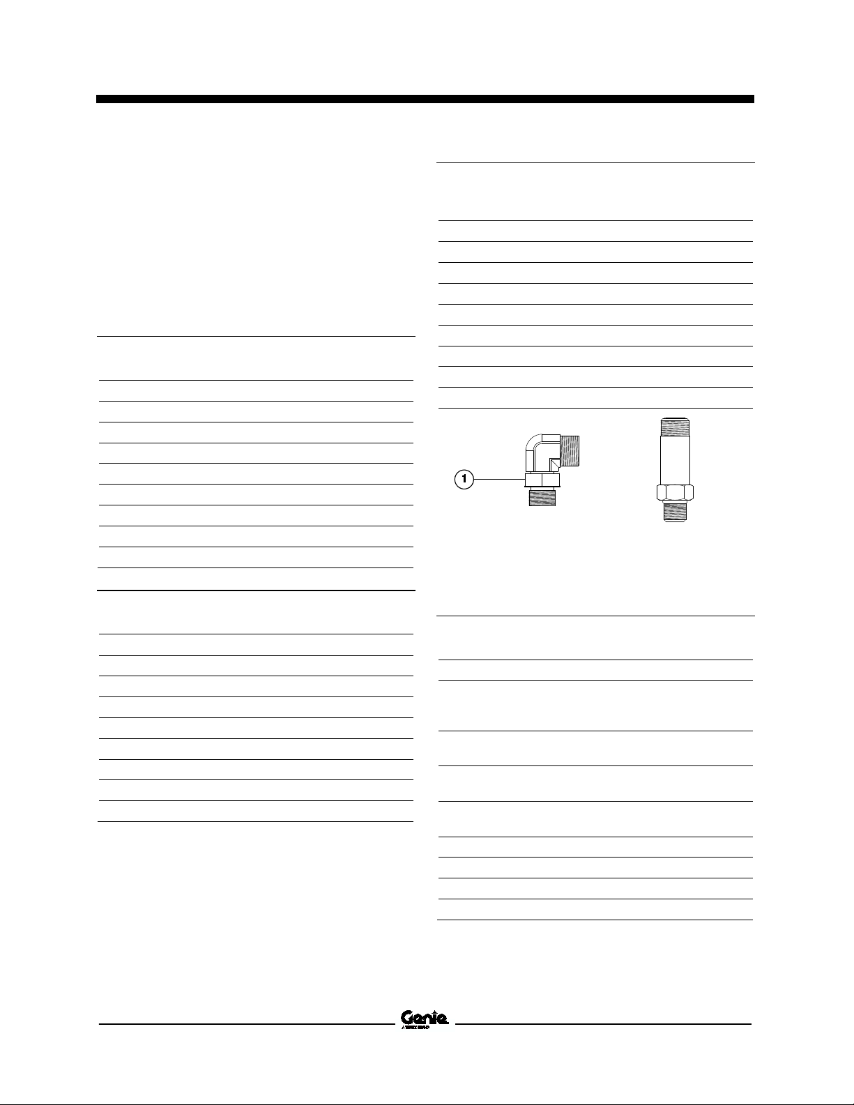
Adjustable Fitting Non-adjustable fitting
1 jam nut
JIC 37° Fittings
(swivel nut or hose connection)
SAE Dash Size Thread Size Flats
-4 7/16-20 2
-6 9/16-18 1 ¼
-8 3/4-16 1
-10 7/8-14 1
-12 1 1/16-12 1
-16 1 5/16-12 1
-20 1 5/8-12 1
-24 1 7/8-12 1
SAE O-ring Boss Port
(tube fitting - installed into Steel)
SAE Dash Size Torque
-4 ORFS / 37° (Adj)
ORFS (Non-adj)
37° (Non-adj)
-6 ORFS (Adj / Non-adj)
37° (Adj / Non-adj)
-8 ORFS (Adj / Non-adj)
37° (Adj / Non-adj)
-10 ORFS (Adj / Non-adj)
37° (Adj / Non-adj)
-12 (All types) 135 ft-lbs / 183 Nm
-16 (All types) 200 ft-lbs / 271.2 Nm
-20 (All types) 250 ft-lbs / 339 Nm
-24 (All types) 305 ft-lbs / 413.5 Nm
15 ft-lbs / 20.3 Nm
26 ft-lbs / 35.3 Nm
22 ft-lbs / 30 Nm
35 ft-lbs / 47.5 Nm
29 ft-lbs / 39.3 Nm
60 ft-lbs / 81.3 Nm
52 ft-lbs / 70.5 Nm
100 ft-lbs / 135.6 Nm
85 ft-lbs / 115.3 Nm
Part No. 38139 AWP Super Series • IWP Super Series 23
Service Manual September 2016
Specifications
Torque Proce dur e
Torque Procedure
Seal-Lok™ fittings
1 Replace the O-ring. The O-ring must be
replaced anytime the seal has been broken.
The O-ring cannot be re-used if the fitting or
hose end has been tightened beyond finger
tight.
Note: The O-ring in Parker Seal Lok™ fittings and
hose end are custom-size O-rings. They are not
standard size O-rings. They are available in the
O-ring field service kit (Genie part number 49612).
2 Lubricate the O-ring before installation.
3 Be sure the O-ring face seal is seated and
retained properly.
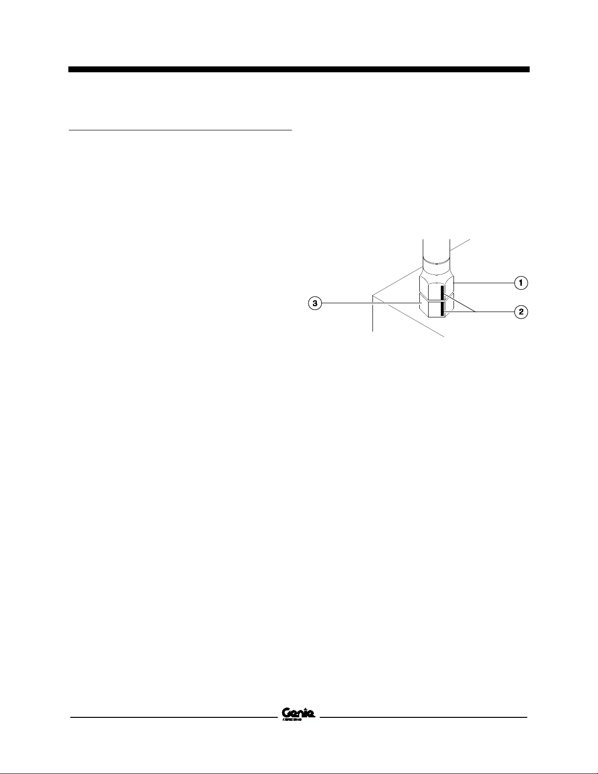
JIC 37° fittings
1 Align the tube flare (hex nut) against the nose
of the fitting body (body hex fitting) and tighten
the hex nut to the body hex fitting to hand tight,
approximately 30 in-lbs / 3.4 Nm.
2 Using a permanent ink marker, make a
reference mark on one the flats of the hex nut
and continue the mark onto the body of the
hex fitting. Refer to Illustration 1.
4 Position the tube and nut squarely on the face
seal end of the fitting, and tighten the nut
finger tight.
5 Tighten the nut or fitting to the appropriate
torque. Refer to the appropriate torque chart in
this section.
6 Operate all machine functions and inspect the
hose, fittings and related components to
confirm there are no leaks.
Illustration 1
1 hex nut
2 reference mark
3 body hex fitting
24 AWP Super Series • IWP Super Series Part No. 38139
September 2016 Service Manual
Specifications
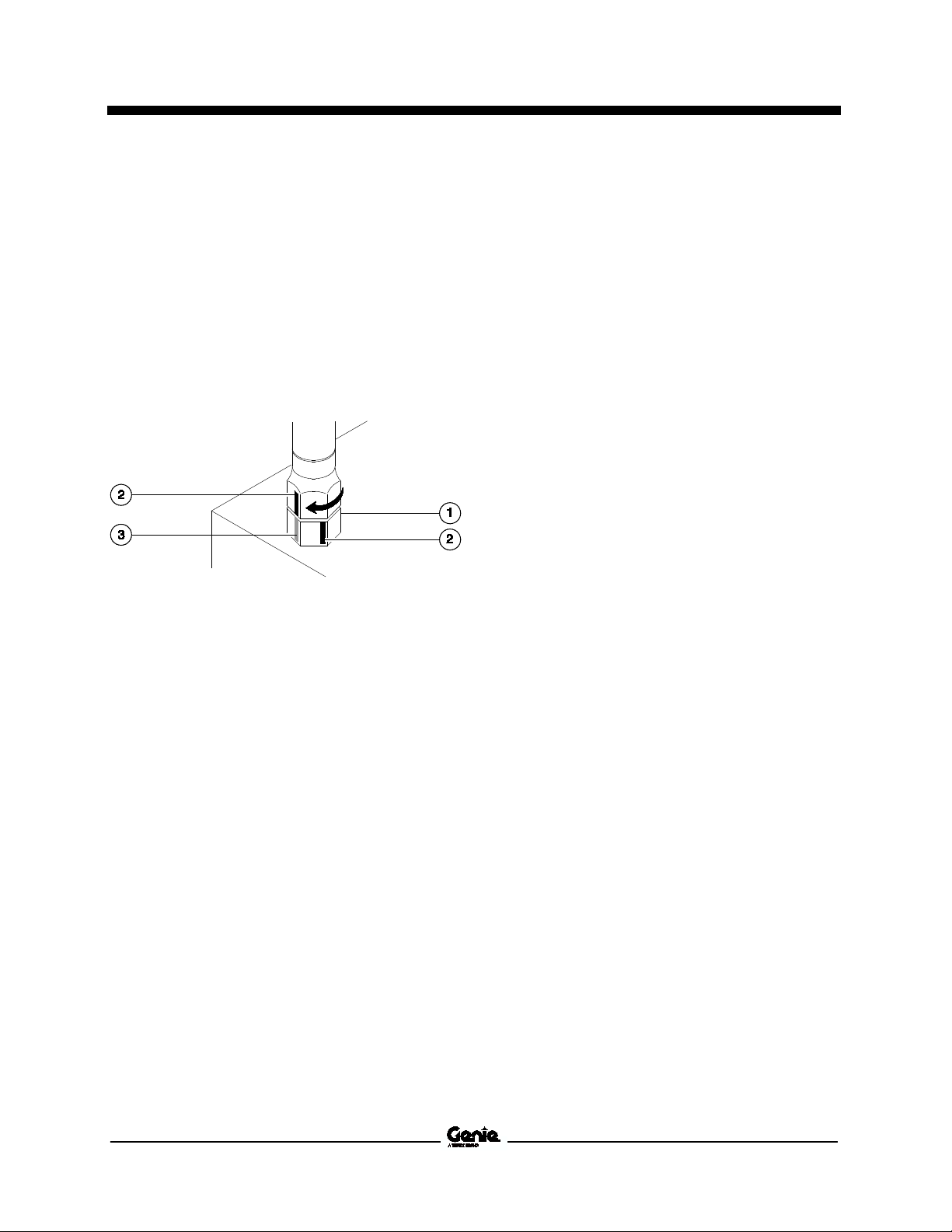
3 Working clockwise on the body hex fitting,
make a second mark with a permanent ink
marker to indicate the proper tightening
position. Refer to Illustration 2.
Note: Use the JIC 37° Fitting table in this section to
determine the correct number of flats, for the
proper tightening position.
Note: The marks indicate the correct tightening
positions have been determined. Use the second
mark on the body hex fitting to properly tighten the
joint after it has been loosened.
Illustration 2
1 body hex fitting
2 reference mark
3 second mark
4 Tighten the hex nut until the mark on the hex
nut is aligned with the second mark on the
body hex fitting.
5 Operate all machine functions and inspect the
hose, fittings and related components to
confirm there are no leaks.
Part No. 38139 AWP Super Series • IWP Super Series 25

Service Manual September 2016
Specifications
SAE and Metr ic F aste ners Tor que C har ts
26 AWP Super Series • IWP Super Series Part No. 38139
September 2016 Service Manual
Failure to perform each
procedure as presented and
scheduled may cause death,
serious injury or substantial
damage.
Scheduled Maintenance Procedures
Section 3 Scheduled M aint ena nce Pr oce dur es
Introducti on
Observe and Obey:
Maintenance inspections shall be completed
by a person trained and qualified on the
maintenance of this machine.
Scheduled maintenance inspections shall be
completed daily, quarterly, and annually as
specified on the Maintenance inspection
Report. The frequency and extent of periodic
examinations and tests may also depend on
national regulations.
Machine Configuration:
Unless otherwise specified, perform each
procedure with the machine in the following
configuration:
• Machine parked on a firm, level surface
• Key switch in the off position with the key
removed
• The red Emergency Stop button in the off
position at both the ground and platform
controls
• Wheels chocked
• All external AC power supply disconnected
from the machine
• Platform in the stowed position
Immediately tag and remove from service a
damaged or malfunctioning machine.
Repair any machine damage or malfunction
before operating the machine.
Use only Genie approved replacement parts.
Machines that have been out of service for a
period longer than 3 months must complete the
quarterly inspection.
Part No. 38139 AWP Super Series • IWP Super Series 27
Service Manual September 2016
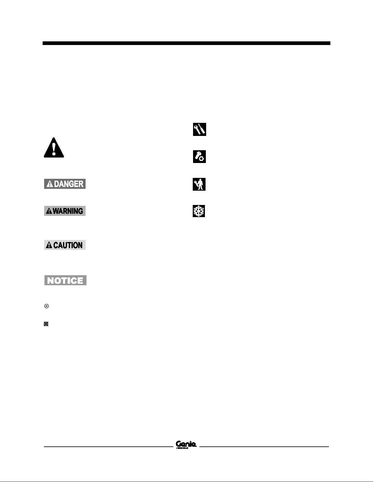
Safety alert symbol—used to alert
personnel to potential personal
injury hazards. Obey all safety
messages that follow this symbol
to avoid possible injury or death.
Indicates a imminently hazardous
situation which, if not avoided, will
result in death or serious injury.
Indicates a potentially hazardous
situation which, if not avoided,
could result in death or serious
injury.
Indicates a potentially hazardous
situation which, if not avoided,
may cause minor
injury.
Indicates a potentially hazardous
situation which, if not avoided,
may result in property damage.
Indicates that tools will be required to
perform this procedure.
Indicates that new parts will be required to
perform this procedure.
Indicates that dealer service will be
required to perform this procedure.
Indicates that a cold motor or pump will be
required to perform this procedure.
Scheduled Maintenance Procedures
About This Section
This section contains detailed procedures for each
scheduled maintenance inspection.
Each procedure includes a description, safety
warnings and step-by-step instructions.
Maintenance Symbols Legend
Note: The following symbols have been used in this
manual to help communicate the intent of the
instructions. When one or more of the symbols
appear at the beginning of a maintenance
procedure, it conveys the meaning below.
Symbols Legend
or moderate
Indicates that a specific result is expected
after performing a series of steps.
Indicates that an incorrect result has occurred
after performing a series of steps.
28 AWP Super Series • IWP Super Series Part No. 38139

September 2016 Service Manual
Inspection Checklist
Daily or every 8 hours A
Quarterly or every 250 hours
A + B
Annually or every 1000 hours
A + B + C
Scheduled Maintenance Procedures
Pre-delivery Preparation Report
The pre-delivery preparation report contains
checklists for each type of scheduled inspection.
Make copies for each inspection. Store completed
forms as required.
Maintenance Schedule
The Scheduled Maintenance Procedures section
and the Maintenance Inspection Report have been
divided into subsections. Use the following chart to
determine which group(s) of procedures are
required to perform a scheduled inspection.
Maintenance Inspection Report
The maintenance inspection report contains
checklists for each type of scheduled inspection.
Make copies of the Maintenance Inspection Report
to use for each inspection. Maintain completed
forms for a minimum of 4 years or in compliance
with your employer, jobsite and governmental
regulations and requirements.
Part No. 38139 AWP Super Series • IWP Super Series 29

Service Manual September 2016
This page intentionally left blank.
30 AWP Super Series • IWP Super Series Part No. 38139
 Loading...