

Genie 37000U Owner’s Manual


OVERVl F POTENTIALHAZARDS
READTHISSAFETYINFORMATI N
Garage doors are large, heavy objectsthat movewiththe help of springs under high tension and electric motors.Since moving
objects, springs under tension, and electric motorscan cause injuries, your safetyandthe safety of others depend on the owner or
user of this system to read, understandand implementthe informationinthis manual. Ifyou havequestions or do NOT
understandthe information presented,contact The Genie Companyoran authorized Genie®Dealer.
The safety alert symbolandfollowing signalwords DANGER,WARNING, and CAUTIONare used throughout this manualto call
attentionto and identifydifferent levels of hazard and special instructions.
,& This is the safety alert symbol. This symbol isplaced next to signalwords and messagesto help you identify
importantsafety information
Theword:
,& DANGERindicates an imminently hazardoussituation which, if NOT avoided,will result in death or serious injury.
,& WARNING indicatesa potentially hazardoussituation which, if NOT avoided, could result in death or serious injury.
CAUTION indicates a potentially hazardoussituationwhich, if NOTavoided, may result in injuryor propertydamage.
Theword ,;0 is used to indicateimportantstepsto be followed, importantconsiderations,or location of parts.
IMPORTANTSAFETYINSTRUCTIONS
READAND FOLLOWALL INSTRUCTIONS
POTENTIAL
HAZARD
MOVINGDOOR
ELECTRICAL
SHOCK
SAVETHESEINSTRUCTIONS
PREVENTION
Keep people clear of openingwhile door is moving.
Do NOTallow children to play with the dooroperator.
Do NOToperate a door that jams or onethat hasa brokenspring.
Turn OFF power before removingoperator cover.
When replacing cover, make sure wires are not pinchedor near
moving parts.
Operator must be properlygrounded.
Do NOTtry to remove,install,repair or adjustsprings or anythingto
which door springparts arefastened,such as, wood blocks,steel
brackets,cablesor other like items.
HIGH
SPRING
TENSION
Installations,repairsand adjustmentsmustbe done by a traineddoor
systemtechnicianusingpropertools and instructions.
PN# 37026500123 05/15/2009
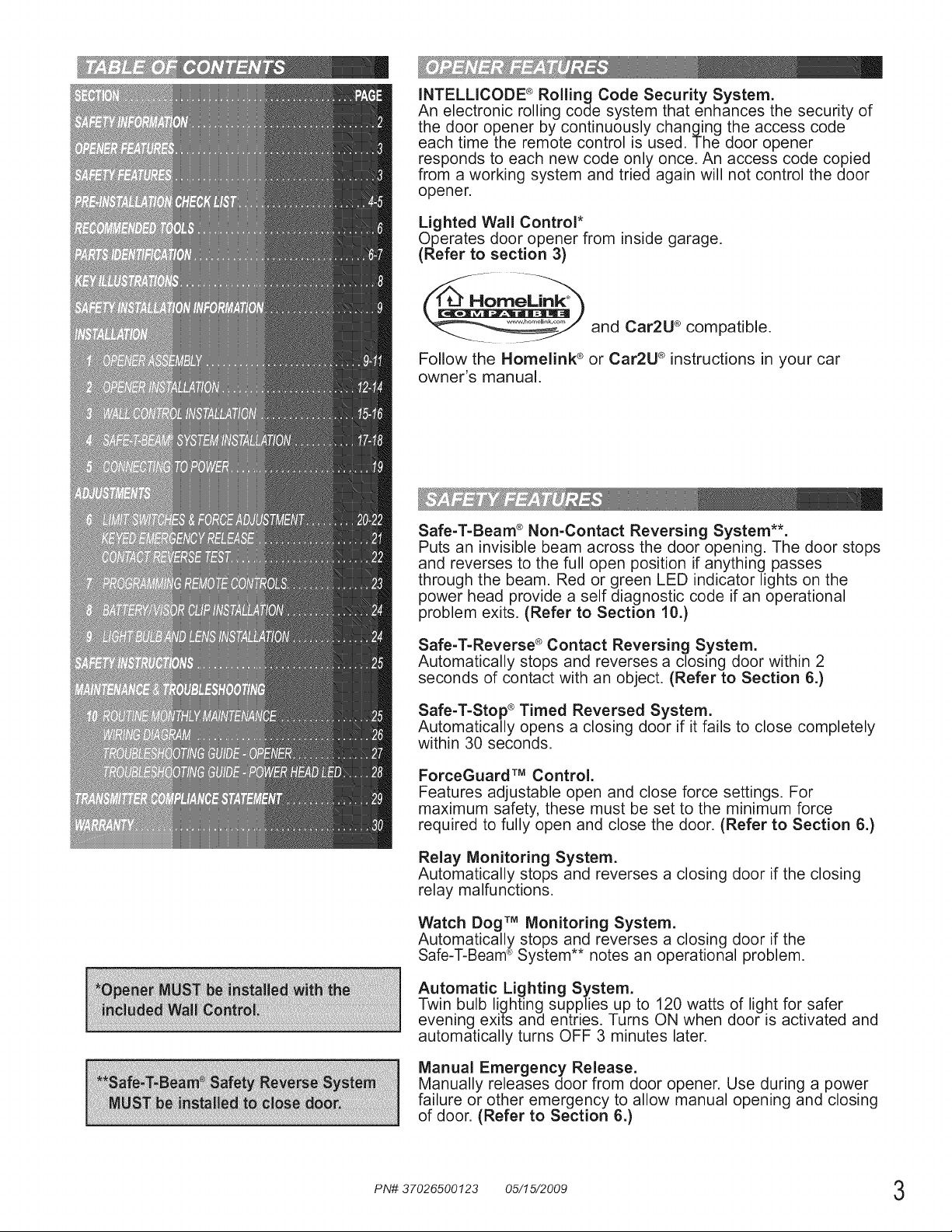
INTELLICODE ®Rolling Code Security System.
An electronic rolling code system that enhances the security of
the door opener by continuously changing the access code
each time the remote control is used. The door opener
responds to each new code only once. An access code copied
from a working system and tried again will not control the door
opener.
Lighted Wall Control*
Operates door opener from inside garage.
(Refer to section 3)
and Car2U ®compatible.
Follow the Homelink ®or Car2U ®instructions in your car
owner's manual.
Safe-T-Beam ®Non-Contact Reversing System**.
Puts an invisible beam across the door opening. The door stops
and reverses to the full open position if anything passes
through the beam. Red or green LED indicator lights on the
power head provide a self diagnostic code if an operational
problem exits. (Refer to Section 10.)
Safe-T-Reverse ®Contact Reversing System.
Automatically stops and reverses a closing door within 2
seconds of contact with an object. (Refer to Section 6.)
Safe-T-Stop ®Timed Reversed System.
Automatically opens a closing door if it fails to close completely
within 30 seconds.
ForceGuard TM Control.
Features adjustable open and close force settings. For
maximum safety, these must be set to the minimum force
required to fully open and close the door. (Refer to Section 6.)
Relay Monitoring System.
Automatically stops and reverses a closing door if the closing
relay malfunctions.
Watch Dog TM Monitoring System.
Automatically stops and reverses a closing door if the
Safe-T-Beam®System notes an operational problem.
Automatic Lighting System.
Twin bulb lighting supplies up to 120 watts of light for safer
evening exits and entries. Turns ON when door is activated and
automatically turns OFF 3 minutes later.
Manual Emergency Release.
Manually releases door from door opener. Use during a power
failure or other emergency to allow manual opening and closing
of door. (Refer to Section 6.)
PN# 37026500123 05/15/2009 3
Thsgs to co_"_s de__f you a_e p_an s ng to _©o_ t_you_o_'self,_
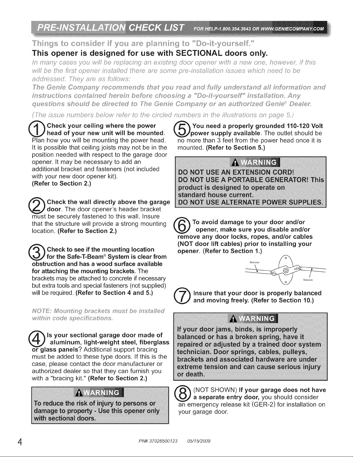
This opener is designed for use with SECTIONAL doors only.
_? De Sse £_s8 operer insX,;::stledSeso ace some pso-ZsIstlsIk/J) hs_es <iJ iot need Jl<>be
s</<:/mssed TTey s_}) as fL>/Cows:
_7_e Gese Oompsny £s_cemme£_7 SSs8 you sssd ssc_ @/y £ sdes/s_snd aS nfs_s_sdos and
q!ues_o_s shouFd be dMs, cSed _'o N%e Ge_"_Fe Co sN}/0_" sN ss_'#_o;'_zed Ge_"_s _,©esIe£
(The Lssue _ur?sL?e_{_beMw mrS:?;;k> ;l(e cS_c/ed ;;,_mi?ei's i_ i!te iIl_srx}IM_s o) pi{?£e 5;'
Check your ceiling where the power
head of your new unit will be mounted.
Plan how you will be mounting the power head.
It is possible that ceiling joists may not be in the
position needed with respect to the garage door
opener. It may be necessary to add an
additional bracket and fasteners (not included
with your new door opener kit).
(Refer to Section 2.)
Check the wall directly above the garage
door. The door opener's header bracket
must be securely fastened to this wall. Insure
that the structure will provide a strong mounting
location. (Refer to Section 2.)
Check to see if the mounting location
for the Safe-T-Beam ®System is clear from
obstruction and has a wood surface available
for attaching the mounting brackets. The
brackets may be attached to concrete if necessary
but extra tools and special fasteners (not supplied)
will be required. (Refer to Section 4 and 5.)
You need a properly grounded 110-120 Volt
power supply available. The outlet should be
no more than 3 feet from the power head once it is
mounted. (Refer to Section 5.)
To avoid damage to your door and/or
opener, make sure you disable and/or
remove any door locks, ropes, and/or cables
(NOT door lift cables) prior to installing your
opener. (Refer to Section 1.)
insure that your door is properly balanced
and moving freely. (Refer to Section 10.)
_?_h':_ cede spec[fics_e _s
is your sectional garage door made of
aluminum, light-weight steel, fiberglass
or glass panels? Additional support bracing
must be added to these type doors. If this is the
case, please contact the door manufacturer or
authorized dealer so that they can furnish you
with a "bracing kit." (Refer to Section 2.)
PN# 37026500123 05/15/2009
(NOT SHOWN) If your garage does not have
a separate entry door, you should consider
an emergency release kit (GER-2) for installation on
your garage door.
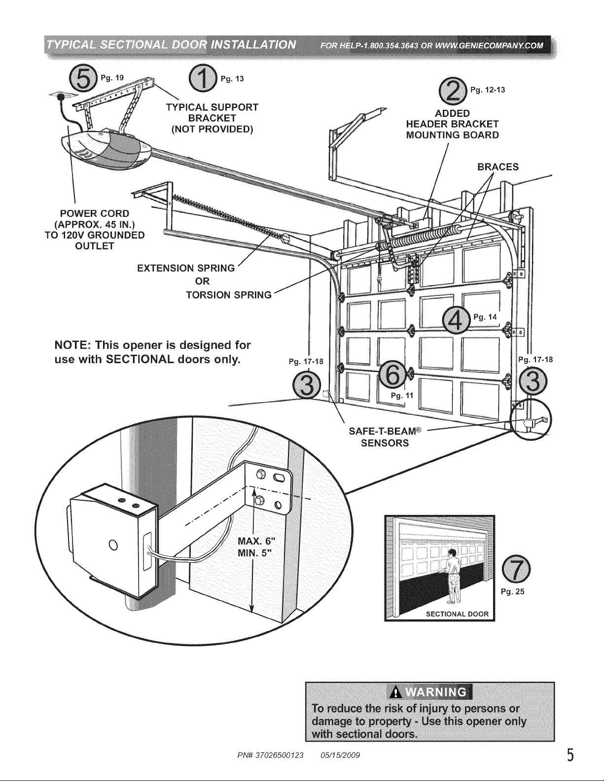
TYPICAL SUPPORT
BRACKET
(NOT PROVIDED)
POWER CORD
(APPROX. 45 iN.)
TO 120V GROUNDED
OUTLET
EXTENSION SPRING
OR
TORSION SPRING
NOTE: This opener is designed for
use with SECTIONAL doors only.
Pg. 13
Pg. 17-18
Pg. 12-13
ADDED
HEADER BRACKET
MOUNTING BOARD
BRACES
Pg. 17-18
SAFE=T=BEAM®
SENSORS
Pg.25
SECTmONALDOOR
PN# 37026500123 05/15/2009 5
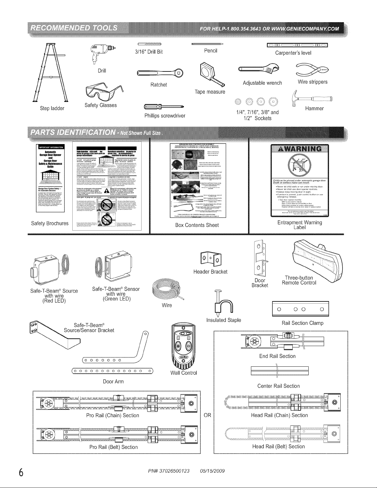
Drill
3/16" Drill Bit
Pencil
I o I_JI c ) I_JI c ) I_JI o II
Carpenter'slevel
Stepladder
1t81t1_
Safety Brochures
Safety Glasses
Ratchet
Phillipsscrewdriver
BoxContents Sheet
Tapemeasure
_E5727:
Adjustablewrench Wire strippers
1/4",7/16", 3/8"and
1/2" Sockets
Child can be pinned under automatic garage door.
•N_wr I_tchild w_lkorrun under ,_ovin_ d_or
•N_ver I_tchild us_ door opener controls
_Al_ys k_p moving door in sight
•_ p_r_n is pinned pushcontrol button orus_
e,_erg_n_y relea_,
,d_,fo,............... djuo_o,....
Entrapment Warning
Hammer
Label
Safe-T-Beam®Source Safe-T-Beam®Sensor
with wire with wire
(Red LED) (Green LED)
Safe-T-Beam®
Sensor Bracket ?
0 0 0 0 0 0 0
O O O O O O O O O O O O O O
DoorArm
Pro Rail (Chain) Section
O
Wire
Wall Control
Header Bracket
InsulatedStaple
OR
Door
Bracket
End RailSection
Three-button
RemoteControl
0 0 0 0
Rail Section Clamp
[ ]
Center Rail Section
Head Rail (Chain) Section
PN# 37026500123 05/15/2009

iiiiill,_Ii!ii'i!iliii;il_!ii;il_!ii;ii!iii!iii!iiiii!iiiiiii;!iii;!iiiiii_ii!i!_ii_i_ii_iii_i_::i!iii!,i!ii_!iiii_iilii:i!i_ili!_!!_i!iii:iil!iii_il_iii!i!iili_iiii_i_i!ii'i'ii'ii::i_i!i_ii_i_iliiii_iillii_i_ii_;il_;ii_;ii_;ii_;ii_;ii_;ii_;ii_;ii_;ii_;ii_;ii_;ii_;ii_;ii_;ii_;ii_;ii_;ii_;ii_;ii_;ii_;ii_;ii_;ii_;ii_;ii_;ii_;ii_;ii_;ii_;ii_;ii_;ii_;ii_;ii_;ii_;ii_;ii_;ii_;ii_;ii_;ii_;ii_;ii_;ii_;ii_;ii_;ii_;ii_;ii_;ii_;ii_;iii_i!
0 RAILSECTION CLAMP 2
RAILCLAMP BOLT 5/16 -18 x 5/8" 8
HEX FLANGE NUT 5/16-18 8
1 BOLT - 5/16 -18 x 1/2" 3
2 CLEVIS PIN, LONG 5/16" x 3" 1
COTTER PIN 1
HEADER BRACKET 1
LAG SCREW 5/16" x 2" 2
3 HEX BOLT- 5/16 -18 x 3/4" 5
HEX FLANGE NUT - 5/16 -18 5
LAG SCREW - 5/16" x 2" 2
4 SELF DRILLING SCREW 1/4 -20 x 3/4" 3
DOOR BRACKET 1
5 HEX BOLT- 5/16 -18 x 3/4" 3
SELF LOCKING NUT - 5/16 -18 1
HEX FLANGE NUT - 5/16 -18 2
CLEVIS PIN - 5/16" x 3/4" 1
COTTER PIN 1
6 WALL CONTROL ASSEMBLY 1
PAN HEAD PHILLIPS SCREW #4-24 x 1" 2
7 13 MM INSULATED STAPLE 30
8 Safe-T-Beam ®SOURCE/SENSOR BRACKET 2
PHILLIPS HEX SCREW #10-16 x 1- 1/4" 4
I WIRE NUT (GREY) 4
NONUMBER REMOTE WITH BATTERY 1
NO BAG Safe-T-Beam ®SOURCE/SENSOR & WIRE SET 1
NONUMBER LIGHT COVER - WHITE 2
Rail Clamp Bolt _ 5/16 _18 x 5/8"
#10_16 x 1_1/4" Phillips Hex Screw
[]==n:n:=>
#4-24 x 1" Pan Head
Phillips Screw
Lag screw * 5/16" x 2"
Wire Nut
©
Self Locking Nut
5/16 _18
©
Hex Flange Nut
5/16 _18
©
Hex Flange Nut
1/4 _20
Self-drilling Screw
1/4 _20 x 3/4"
5/16" x 3/4"
C[] Clevis pin
Hex Bolt _5/16 _18x 3/4" Hex Bolt _5/16 _18x 1/2"
MISSING ANY PARTS? Please call toll free - 1.800.354.3643
DO NOT RETURNTO POINT OF PURCHASE.
IMPORTANT!- Information needed when calling
• Model number- (located onpackaging)
• Store, city, state, and date of purchase
PN# 37026500123 05/15/2009 7
Clevis pin, long 5/16" x 3"
Cotter pin
Shoulder Bolt
5/16 _18 x 1"
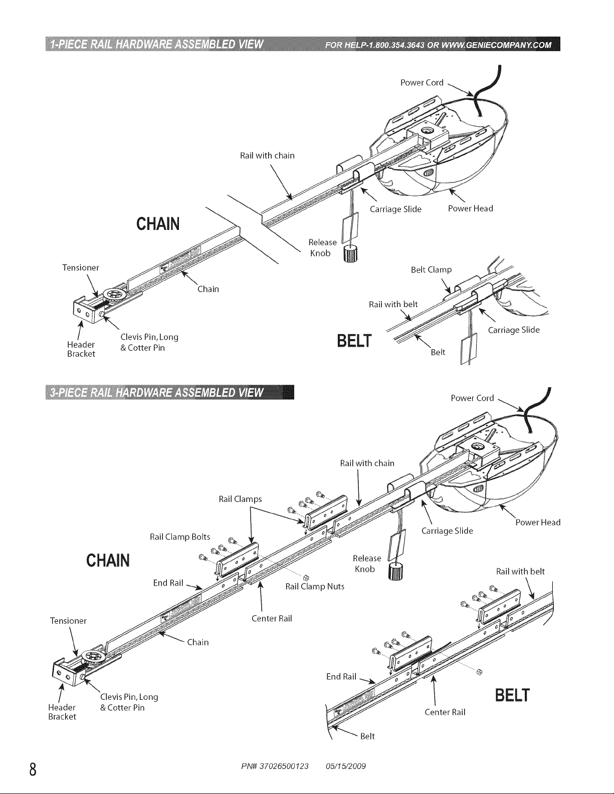
CHAIN
Tensioner
t Clevis Pin, Long
Header & Cotter Pin
Bracket
Chain
Railwithchain
Release
Knob
BELT _Belt
PowerCord
Carriage Slide Power Head
Belt Clamp
Rail
l Carriage Slide
Rail with chain
Ra,Clam_s __
t_UAIM
_#1 I_,11_i
/ 2';Vo';_irn_Long BELT
Header F_T_Y_JJ Center Rail
Bracket
Rail Clamp Bolts_.__/°_-,,._//k.-,,_/Ci_k___._ enobease_ Carriage Slide
-_ Chain ....
"JHf_---_ _ Rail with belt
\ .... Belt
PN# 37026500123 05/15/2009
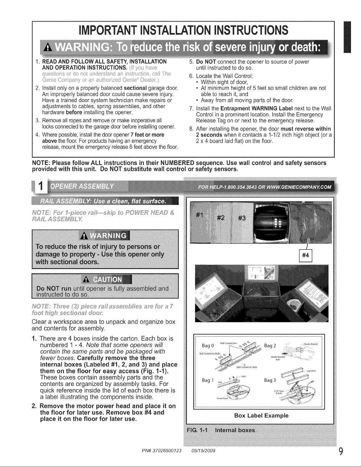
IMPORTANTINSTALLATIONINSTRUCTIONS
I
1. READAND FOLLOW ALL SAFETY, INSTALLATION 5.
AND OPERATION INSTRUCTIONS.( yo_J_ave
qvesto_so do o u_dosS;,_v_i_:s__st_;cto_ ca/ i/% 6.
_,, L/34 :S ., <_
2. Installonly on a properly balanced sectional garage door.
An improperly balanced door could cause severe injury.
Have a trained door system technician make repairs or
adjustments to cables, spring assemblies, and other 7.
hardware before installing the opener.
3. Removeall ropesand removeor make inoperativeall
locksconnectedtothe garagedoor beforeinstallingopener. 8.
4. Wherepossible,installthe dooropener7 feet or more
above the floor. Forproductshavingan emergency
release,mounttheemergencyrelease6 feet abovethefloor.
NOTE: Please follow ALL instructions in their NUMBERED sequence. Use wall control and safety sensors
provided with this unit. Do NOT substitute wall control or safety sensors.
Do NOT connect the opener to source of power
until instructed to do so.
Locate the Wall Control:
• Within sight of door,
• At minimum height of 5 feet so small children are not
able to reach it, and
• Away from all moving parts of the door.
Installthe Entrapment WARNING Label next to the Wall
Control in a prominent location. Installthe Emergency
Release Tagon or next to the emergency release.
After installing the opener,the door must reverse within
2 seconds when it contacts a 1-1/2 inch high object (or a
2 x 4 board laid fiat) on the floor.
NOTE: Throe J) p£/?ce _s:!_£ssse£ bSes am £}_ s 7
/:o0_ h){Fh sec_ions doo_,:
Clear a workspace area to unpack and organize box
and contents for assembly.
1. There are 4 boxes inside the carton. Each box is
numbered 1 - 4. Note that some openers will
contain the same parts and be packaged with
fewer boxes. Carefully remove the three
internal boxes (Labeled #1, 2, and 3) and place
them on the floor for easy access (Fig. 1-1).
These boxes contain assembly parts and the
contents are organized by assembly tasks. For
quick reference inside the lid of each box there is
a label illustrating the components inside.
2. Remove the motor power head and place it on
the floor for later use. Remove box #4 and
place it on the floor for later use.
PN# 37026500123 05/15/2009 9
Box Label Example
 Loading...