

Page 1

BELT/CHAIN DRIVE GARAGE DOOR OPENER MODELS
1035, 2033, 2035, 2036, 2053, 2055, 3033, 3035,
3053, 3055, 7033, 7035, 7053, 7055
PROGRAMMING, OPERATION
& MAINTENANCE MANUAL
Includes
The Included
For use with residential sectional overhead garage doors ONLY.
Homelink® and Car2U® compatible
INTELLICODE® Remote Control.
Safe-T-Beam® system
MUST be installed to close the door. DO NOT use other brands or types.
DO NOT return product to store,
visit www.GenieCompany.com
STOP
or call Customer Service at: 1-800-35-GENIE,
For SilentMax Connect® Models, call 1-866-599-4995
!
WARNING
To reduce the risk of injury to persons or damage to property, use this opener only with a sectional residential door.
!
AVERTISSEMENT
Por reduire le risque de blessures ou de dommages materials, utillsez cet ouvre-porte uniquement pour une porte
a section re sidentielie.
INSTALLER: LEAVE THIS MANUAL WITH HOMEOWNER
HOMEOWNER: SAVE THIS MANUAL FOR FUTURE REFERENCE
©2017 GMI Holdings, Inc d/b/a The Genie Company, the Genie logo, Intellicode, Safe-T-Reverse, SmartSet, Sure-Lock, Door Detect, and Safe-TBeam, are trademarks of The Genie Company. All other trademarks are property of their rightful owners. Consistent with our policy of continuing product improvements, we reserve the right to change product speci cations without prior notice or obligations. HomeLink is a registered
trademark of Gentex Corporation. Car2U is a registered trademark of Lear Corporation.
Patents www.GenieCompany.com/patents
38967503545_EnglishWeb 09/2017
Page 2
T
INDEX
Safety Information
1
Safety Noti cations ................................................. 4
Important Safety Instructions ............................. 5
Features
2
Safety Features ......................................................... 6
Opener Features ...................................................... 6
Programming Information
3
Introduction .............................................................. 7
Overview of Powerhead Controls...................... 7
Travel Limits
Closing Garage Door (DOWN Limit) ................. 8
Opening Garage Door (UP Limit)....................... 9
Force Control ...........................................................10
Contact Reverse Test ............................................10
Contact Reverse Adjustment ............................10
Remote Control Programming .........................11
Maintenance and Adjustments
4
Important Safety Instructions ...........................12
Regular Maintenance ...........................................13
Remote Battery Replacement ...........................13
Light Bulb Replacement .....................................14
Chain/Belt Tension ................................................14
Carriage Adjustment for Release .....................15
Adjustment Guides ...............................................15
Resetting Travel Limits .........................................15
Locating Safe-T-Beam® Pairs .............................16
Wire Diagram ..........................................................16
Troubleshooting ........................................... 17-18
5
Genie Battery Backup Installation ..............19
6
Optional Programming & Accessories
7
Clearing Memory for Remotes .........................20
Programming Vehicle Remotes ........................21
Programming Wireless Keypad .................22-23
Parts ................................................................... 24-27
8
DASMA Information ................................... 28-31
9
Warranty ..................................................................32
SAVE THESE INSTRUCTIONS
READ AND FOLLOW ALL INSTRUCTIONS
FCC Part 15.21 Statement:
Changes or modi cations not expressly
approved by the party responsible for
compliance could void the user’s authority to
operate the equipment.
FCC / IC Statement:
This device complies with FCC Part 15
and Industry Canada licence-exempt RSS
standard(s). Operation is subject to the
following two conditions: (1) this device
may not cause harmful interference, and
(2) this device must accept any interference
received, including interference that may cause
undesired operation of the device.
Le présent appareil est conforme aux CNR
d’Industrie Canada applicables aux appareils
radio exempts de licence. L’exploitation est
autorisée aux deux conditions suivantes : (1)
l’appareil ne doit pas produire de brouillage,
et (2) l’utilisateur de l’appareil doit accepter
tout brouillage radioélectrique subi, même si le
brouillage est susceptible d’en compromettre le
fonctionnement.
Page 3
Thank you for purchasing a
Genie® brand garage door
opener. The leader in garage door
opener technology.
Please take a moment to preview this manual and assembly poster
to ensure that you have the proper tools and skill set to install a new
garage door opener. Pay particular attention to all Safety Warnings,
Cautions and Information. Remember, your garage door is the largest
and heaviest moving object in your home.
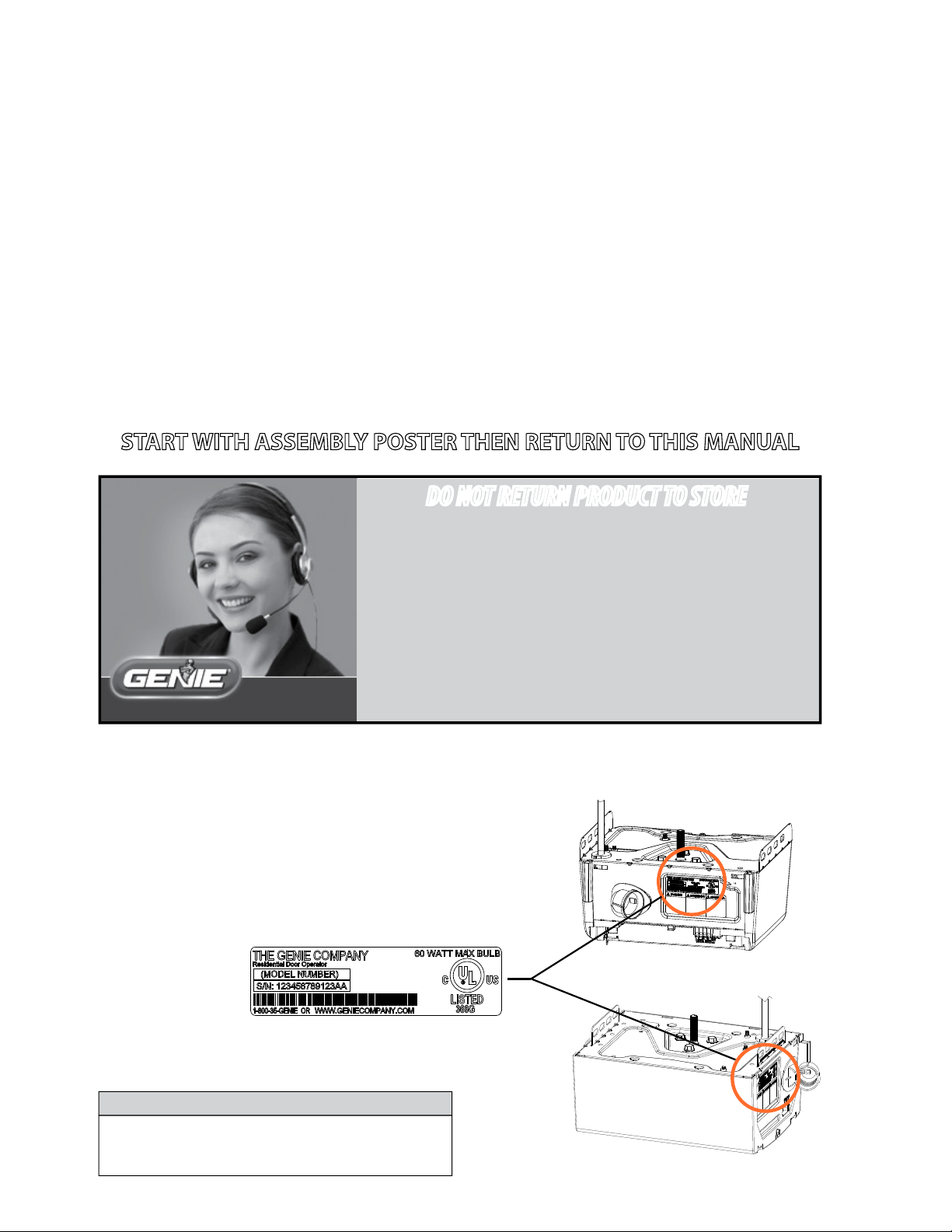
START WITH ASSEMBLY POSTER THEN RETURN TO THIS MANUAL
DO NOT RETURN PRODUCT TO STORE
If you require assistance or have any questions,
a knowledgeable Genie Service Technician is just
a phone call away at:
1-800-35-GENIE (1-800-354-3643)
Or visit our website at:
www.GenieCompany.com
Before setting up your new garage door opener, please locate and record the model plate on the
opener. This information will be necessary should you seek technical support via our website,
customer support department or local servicing Genie dealer.
Model Number:______________________________
Serial Number:_______________________________
1 Bulb Models
NOTE
Keep an original or photocopy of receipt of
opener purchase for warranty purposes.
2 Bulb Models
3
Page 4
!
!
!
!
!
!
!
!
1
SAFETY NOTIFICATIONS & INSTRUCTIONS
OVERVIEW OF POTENTIAL HAZARDS
READ THIS SAFETY INFORMATION
Garage doors are large, heavy objects that move with the help of springs under high tension and electric motors. Since moving objects, springs under tension,
and electric motors can cause injuries, your safety and the safety of others depend on you reading the information in this manual. If you have questions or do
not understand the information presented, call your nearest trained door system technician or visit our website at www.geniecompany.com.
CONVENTIONS USED IN THESE INSTRUCTIONS
The following safety alert symbol and signal words are used throughout this manual to call attention to and identify di erent levels of hazards and special
instructions.
This is the safety alert symbol. This symbol alerts you to potential hazards that can kill or hurt you and others. All safety messages will follow the safety alert
symbol and the word
Tous les messages concernant la sécurité seront indiqués après un symbole d’alerte de la sécurité et l’une des mentions suivantes “DANGER”,
”AVERTISSEMENT” ou “MISE EN GARDE”.
“DANGER”, “WARNING”, or
• DANGER
• WARNING
•
•
• DANGER signale une situation dangereuse imminente qui, si elle n’est pas évitée, risque d’entraîner des blessures graves, voire mortelles.
• AVERTISSEMENT signale une situation potentiellement dangereuse qui, si elle n’est pas évitée, risque d’entraîner la mort ou des blessures
• MISE EN GARDE signale une situation potentiellement dangereuse qui, si elle n’est pas évitée, risque d’entraîner des blessures ou des
• Le terme REMARQUE est utilisé pour signaler les étapes importantes à suivre ou d’importants éléments à prendre en considération.
indicates an imminently hazardous situation which, if NOT avoided, will result in death or serious injury.
indicates a potentially hazardous situation which, if NOT avoided, could result in death or serious injury.
CAUTION
indicates a potentially hazardous situation which, if NOT avoided, may result in injury or property damage.
The word
graves.
dommages matériels.
NOTE is used to indicate important steps to be followed or important considerations.
“CAUTION”.
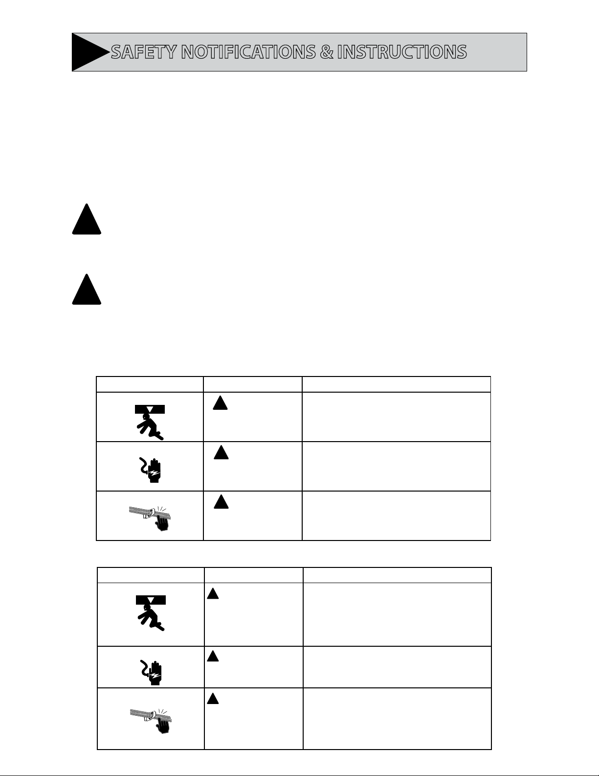
IMPORTANT SAFETY INSTRUCTIONS
POTENTIAL HAZARD EFFECT PREVENTION
MOVING DOOR
ELECTRICAL SHOCK
HIGH SPRING TENSION
WARNING
Could result in Serious
Injury of Death
WARNING
Could cause Serious
Injury or Death
WARNING
Could cause Serious
Injury or Death
Do Not operate unless the doorway is in sight and free of
obstructions. Keep people clear of opening while door is moving.
Do Not allow children to play with the door opener.
Do Not change opener control to momentary contact unless and
external reversing means is installed.
Do Not operate a door that jambs or one that has a broken spring.
Turn o electrical power before removing opener cover.
When replacing the cover, make sure wires are not pinched or near
moving parts.
Opener must be electrically grounded.
Do Not try to remove, repair or adjust springs or anything to which
door spring parts are fastened such as wood block, steel brackets,
cables or any other structure or like item.
Repairs and adjustments must be made by a trained service
representative using proper tools and instructions.
IMPORTANTES CONSIGNES DE SÉCURITÉ
DANGER POTENTIEL EFFET PRÉVENTION
PORTE EN MOUVEMENT
CHOC ÉLECTRIQUE
TENSION ÉLEVÉE RESSORT
4
AVERTISSEMENT
Pourrait entraîner des
blessures graves voire la mort
AVERTISSEMENT
Pourrait entraîner des
blessures graves voire la mort
AVERTISSEMENT
Pourrait entraîner des
blessures graves voire la mort
Utiliser uniquement si la porte est en vue et libre de tout obstacle.
Ne laisser personne se tenir dans l’ouverture de la porte pendant
qu’elle est en mouvement.
Ne pas permettre aux enfants de jouer avec l’opérateur de la porte.
Ne pas modi er la commande de l’opérateur à contact momentané
à moins qu’un moyen d’inversion externe soit installé.
Ne pas faire fonctionner une porte qui bloque ou dont le ressort
est cassé.
Couper le courant avant d’enlever le couvercle de l’opérateur.
Lorsque le couvercle doit être remplacé, s’assurer que les ls ne sont
ni coincés ni près des pièces mobiles.
L’opérateur doit être correctement mis à la terre.
Ne pas essayer d’enlever, réparer ni ajuster les ressorts ou
toute autre pièce à laquelle le ressort de la porte est attaché, y
compris blocs de bois, supports en acier, câbles ou autres articles
semblables.
Les réparations et les réglages doivent être e ectués par
technicien quali é qui se sert d’outils appropriés et qui respecte les
instructions.
Page 5
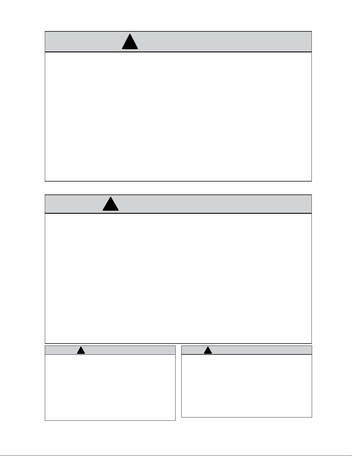
IMPORTANT INSTALLATION INSTRUCTIONS
WARNING
!
TO REDUCE THE RISK OF SEVERE INJURY OR
DEATH
READ AND FOLLOW ALL SAFETY, INSTALLATION AND OPERATION INSTRUCTIONS. If you have any questions or do not
understand an instruction, call The Genie Company.
• DO NOT install opener on an improperly balanced door. An improperly balanced door could cause severe injury. Repairs
and adjustments to cables, spring assembly and other hardware must be made by a trained service person using proper
tools and instructions.
• Remove all ropes, and disable all locks connected to the door before installing opener.
• Where possible, install the door opener 7 feet or more above the oor. For products having an emergency release,
mount the emergency release within reach, but at least 6 feet above the oor and avoiding contact with vehicles to
avoid accidental release. DO NOT use emergency release cord to pull door.
• DO NOT connect the opener to the source of power until instructed to do so.
• Locate the wall control button: A) Within sight of door. B) At a minimum height of 5 feet, so small children cannot reach
it. C) Away from all moving parts of the door.
• Install the entrapment WARNING label next to the wall button or console, in a prominent location. Install the emergency
release handle on the emergency release cord.
• The opener must reverse when the door contacts a 1-1/2 inch high object on the oor at the center of the doorway. This
is about the size of a 2” x 4” board laid at.
IMPORTANTES INSTRUCTIONS D’INSTALLATION
!
AVERTISSEMENT
POUR RÉDUIRE LES RISQUES DE BLESSURES GRAVES VOIRE
MORTELLES
LIRE ET SUIVRE ATTENTIVEMENT TOUTES LES INSTRUCTIONS D’INSTALLATION ET DE FONCTIONNEMENT AINSI QUE TOUTES LES CONSIGNES
DE SÉCURITÉ. Si vous avez des questions ou si vous ne comprenez pas une instruction, veuillez contacter directement The
• NE PAS installer l’opérateur sur une porte mal équilibrée. Celle-ci pourrait entraîner de graves blessures. Les réparations
et les réglages des câbles, ensembles de ressort ou tout autre article de quincaillerie doivent être e ectués par un professionnel qui se sert d’outils appropriés et qui respecte les instructions.
• Enlever toutes les cordes et désactiver toutes les verrous de la porte avant l’installer l’opérateur.
• Dans la mesure du possible, installer l’ouvre-porte à 2,1 m ou plus au-dessus du sol. Pour les produits dotés d’un cordon
de déclenchement d’urgence, installer le déclenchement d’urgence mais au moins à 1,8 m au-dessus du sol en évitant
tout contact avec les véhicules pour éviter qu’ils ne soient déclenchés accidentellement. NE PAS utiliser d’urgence cordon de libération pour ouvrir ou fermer la porte.
• NE PAS connecter l’opérateur à la source d’alimentation tant que l’instruction n’est pas donnée.
• Repérer la console murale: A) En vue de la porte. B) À une hauteur minimale de 1,5 m a n que les jeunes enfants ne
puissent pas l’atteindre. C) Loin de toutes pièces mobiles de la porte du garage.
• Placer l’étiquette d’AVERTISSEMENT en cas de coinçage à proximité du bouton mural ou de la console de manière à ce
qu’elle soit bien en évidence. Installer la poignée du cordon de déclenchement d’urgence.
• L’opérateur doit s’inverser lorsque la porte entre en contact avec un objet d’une hauteur de 3,8 cm placé sur le sol, au
centre de l’ouverture de la porte. Ceci équivaut environ à une planche de 5 x 10 cm posée à plat sur le sol.
!
WARNING
Opener is equipped with grounded electrical plug for
your protection, and only ts grounded electrical
outlets. DO NOT alter plug in any way! If your have no
grounded outlets, have one installed by a licensed
electrician. Opener must be properly grounded to prevent
personal injury and equipment damage. NEVER USE AN
EXTENSION CORD! Check local building codes for any
requirement that you must have a permanent hard-wired
connection. Permanent hard-wired connections must be
performed by a licensed electrician using proper tools and
instructions.
L’opérateur, qui est équipé d’une prise électrique mise à la terre
pour votre protection est compatible uniquement avec des
prises électriques mises à la terre. NE PAS modi er la che dune
quelconque manière. Si vous n’avez pas de prises mises à la terre,
faites-en installer par un électricien agréé. L’opérateur doit être
correctement mis à la terre pour éviter les blessures corporelles et
des dommages matériels. NE JAMAIS UTILISER DE RALLONGE!
Véri ez les codes locaux des bâtiments pour connexions câblées
permanente. Les connexions câblées permanentes doivent
être e ectuées par un électricien agréé qui se servira d’outils
appropriés et respectera les consignes.
!
AVERTISSEMENT
Genie Company.
5
Page 6
2
SAFETY & STANDARD FEATURES
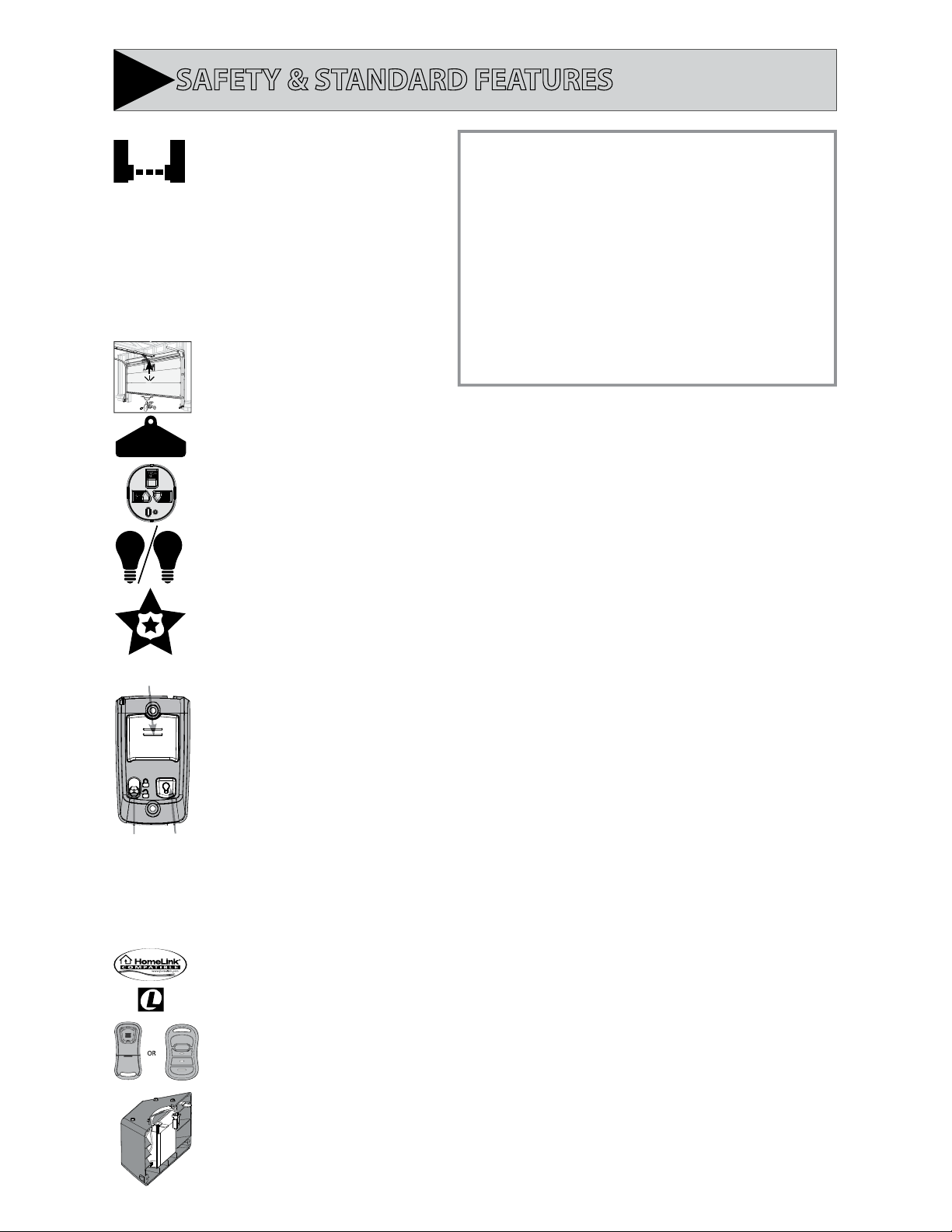
Safe-T-Beam® (STB) Non-Contact
Reversing System
Puts an invisible beam across the door opening. The
door stops and reverses to the full open position if
anything passes through the beam. LED indicator
lights on the powerhead and on the STBs provide
self-diagnostics if an operational problems exists.
Safe-T-Beam® (STB) FUNCTION
1. The Safe-T-Beam® has no e ect on the door during an opening cycle.
2. If the Safe-T-Beam® detects an obstruction when trying to close the
door, it will not allow the door to close.
3. When the garage door is closing, if Safe-T- Beam® is interrupted by
a person or obstacle, the garage door will stop its downward travel
and reverse automatically to its fully opened position.
Door Detect™ Monitoring System
Monitors the Safe-T-Beam® system to ensure proper
functionality and will automatically stop and
reverse a closing door if a problem is detected.
4. If the Safe-T-Beam® System fails, loses power, or is installed
improperly, press and hold the wall console “open/close” button
until the door reaches its fully closed position. If you release
the “open/close” button on the wall console during the closing
movement, the door will reverse automatically to its fully-opened
Safe-T-Reverse® Contact Reversing System
Automatically stops and reverses a closing door
within two seconds of contact with an object.
Manual Emergency Release
Manually releases door from door opener. Used during a power failure or other emergency to allow manual opening and closing of door.
DO NOT use emergency release cord to pull door
®
Electronic Programming
SmartSet
Easily adjust the programming to set limits and program new remotes.
Automatic Lighting System
Single or Dual Bulb lighting system supplies light for safer evening exits and entries. Turn ON when door is activated and automatically
turns OFF 4 minutes later.
Intellicode®
An encryption system that enhances the security of the door opener by continuously changing the access code
each time the remote is used. The door opener responds to each new code only once. An access code copied from
a working system and tried again, will not control the door opener.
position.
1 & 2
Wall Console (With select models)
Operates door opener from inside garage. The wall console has an indicator light with:
Open/Close, Sure-lock™, and independent light control buttons.
1.) Indicator Light
Large white button will display Red when wall console is properly wired and Sure-Lock™ is OFF. When Sure-Lock™
is ON, this light is o .
2.) Open/Close Button
Use this button to open or close garage door. When Sure-Lock™ is ON the Open/Close button will CLOSE the door
only.
NOTE: Constant button pressure in the CLOSE mode will override STB fault in the powerhead and close door.
3.) Independent Light Control Button
Use this button to turn the powerhead lights ON. Powerhead lighting will remain ON until this button is pressed
34
again or a door action has been completed.
4.) Sure-Lock™ Button
When Sure-Lock™ is ON, and the door is closed, the powerhead cannot be activated by the wall console or a
remote.
• Slide switch up to activate Sure-Lock™ (red light goes o ).
• Slide switch down to turn Sure-Lock™ OFF (red light goes on).
Home Link® and Car2U® compatible. See instructions in this manual, refer to the motor vehicle manual or visit
www.geniecompany.com for instructions.
Factory Programmed Remote Control
For ease and speed of installation, the remote included with this opener comes from the factory, pre-programmed.
No additional steps are required to activate the door using the remote.
Genie Battery Backup (BBU)
Available on some models. Provides power to opener in the event of a power failure.
NOTE: Genie Battery Backup will only operate after opener installation is completed and Travel Limits have been
set.
DO NOT INSTALL BATTERY BACKUP UNTIL OPENER IS FULLY INSTALLED AND PROGRAMMED
6
Page 7
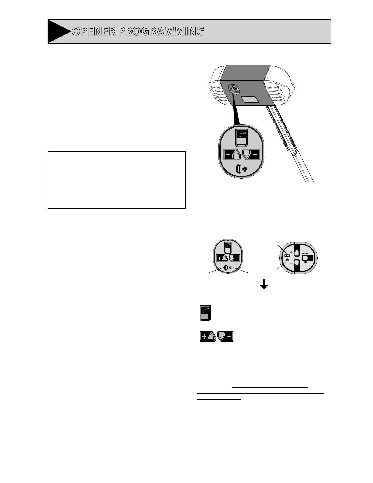
Open Travel
Button
Close Travel
Button
Long LED
Indicator
Round LED
Indicator
Program
Open Travel
Button
Close Travel
Button
Long LED
Indicator
Round LED
Indicator
Program
3
NOTE:
OPENER PROGRAMMING
Before programming the opener, check to make sure there
are no objects in the garage door opening.
INTRODUCTION
Now that the Genie® garage door opener is installed, follow
the steps in this manual to program the opener so that
the door opens and closes properly and all remote devices
operate correctly. The following steps are a guide to setting
opener so it functions properly.
The following steps list the order of programming the
opener’s functional settings for use.
1. “TRAVEL LIMITS”
2. “FORCE CONTROL”
3. “REMOTE PROGRAMMING”
Term De nitions:
Travel Limits Programmable setting to adjust how far door
travels up or down.
Force Control refers to how much power is needed to
move (open/close) a particular door and does NOT require
programming.
Remote Programming synchronizes remote devices
(remote and keypad) with the powerhead.
OVERVIEW OF POWERHEAD CONTROLS
This section describes the programming functions of the
opener. Use the following information to understand the
buttons and LED indicators used to program functions.
ORIENTATION
Standing under the opener’s powerhead – facing the door – looking
up – this is the view you will see of the programming buttons and
LEDs.
2 Light Models 1 Light Models
Powerhead: There are 3 programming buttons and 2 LED
lights on the powerhead. Each of the buttons are used to
enter and complete the setup programming. The LED lights
indicate status or a function change by illuminating ON, OFF,
or ON FLASHING.
There are 3 programs:
1. Door Travel Limits.
This program is used to set how far the door travels up
and down.
2. Force Setting Program.
This program controls the force applied during the
closing and opening of the door. They are factory set
and will rarely require adjustment.
3. Remote Programs (default menu)–only required for
added remote control transmitters.
Describes how to program remotes to sync with
additional remote control devices, wall consoles,
keypads and the powerhead.
NOTE: The 3 programming buttons are for programming ONLY.
These buttons can NOT be used to operate the opener once the
Required Programming section has been successfully completed.
DOOR
Enters into and selects
programming menus.
Moves door up or down during
programming and advances
through menus.
NOTE: Each programming step has a 30 second time limit for completion
after the function is initiated. After 30 seconds, two LED’s will illuminate RED
indicating time has expired and the step must be re-started. Restart the step
as many times as necessary to complete the programming.
• Just remember—the pointed end of the button (like an
arrowhead) points in the direction the carriage will move when
that button is pushed.
7
Page 8
PROGRAMMING DOWN TRAVEL LIMIT
!
WARNING
• Make sure doorway is in full view and clear of obstacles and
people to avoid injury or property damage.
• DO NOT operate this unit from the wall control before LIMITS
are set. Severe damage to the opener could occur.
• The carriage MUST be engaged to turnbuckle BEFORE setting
limits. See installation poster or call Customer Service at
1-800-35-GENIE or visit www.GenieCompany.com.
• DO NOT set limits with Battery Backup attached. AC power
MUST be connected to the opener while setting limits for
proper operation.
!
AVERTISSEMENT
• S’assurer que le passage de la porte est visible et dégagé, à
savoir sans obstacles ni personne a n d’éviter toute blessure
potentielle ou dommage matériel.
• NE PAS utiliser cette unité avec la console murale avant
d’avoir réglé les LIMITES. L’ouvre-porte pourrait subir de
sérieux dommages.
• La tendeur DOIT être engagée dans le chariot AVANT de
régler les limites. Voir le poster d’installation (si fourni) ou
appelez le service clientèle au 1-800-35-GENIE ou visitez le
site www.GenieCompany.com.
• NE PAS xer de limites en mode batterie de secours.
L’alimentation CA DOIT être branchée sur l’ouvre-porte,
pendant le réglage des limites, pour assurer un bon
fonctionnement.
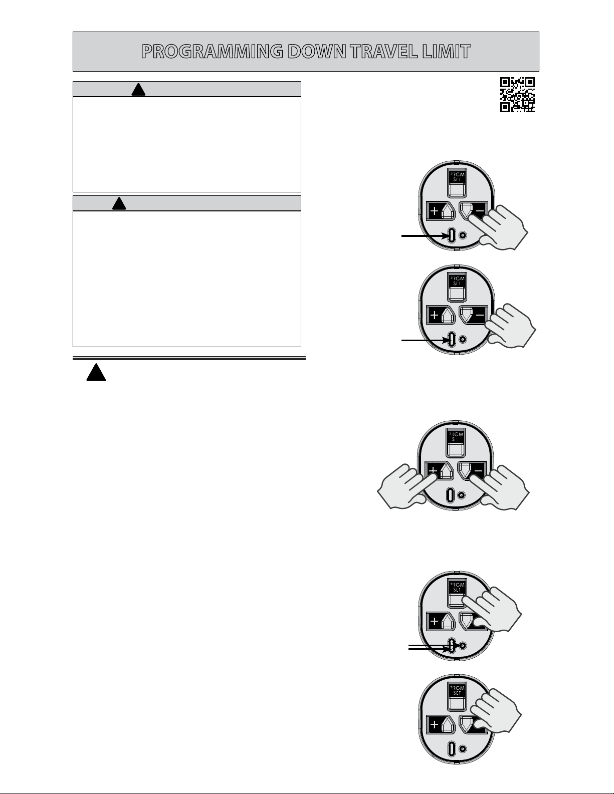
1-2. Enter Programming Mode
HOLD
UNTIL
LED
Lights
Steady Blue
RELEASE
Flashing Blue
!
NOTE:
Carriage should be locked
to opener. Door should rest somewhere
between full open and closed. Do not start
with door fully open or closed.
Programming DOWN Limit:
1. Press and hold the DOWN arrow button.
• Long LED will light BLUE.
2. Release DOWN arrow button.
• Long LED will ash BLUE.
3. Press and hold the DOWN arrow button until
door is fully closed.
• Use the UP arrow button if door closes too
far. Use both UP and DOWN buttons to adjust
close travel as necessary.
Door should rest on the oor until the weather strip
is compressed enough to seal along the width of the
door. Damaged doors or uneven oors may not seal
properly. Repair these conditions to achieve a proper
seal. DO NOT compress seal so much that the door will
bend or buckle.
3. Adjust Door Position
4. Lock Programming
Flashing Blue
PRESS
&
RELEASE
4. Press and release the SET/PRGM button
• Both LEDs will ash BLUE then go out.
The DOWN limit is now programmed.
8
Page 9
PROGRAMMING UP TRAVEL LIMIT
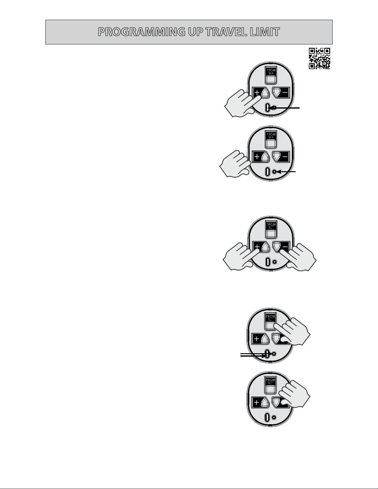
Programming UP Limit:
1. Press and hold the UP arrow button.
• Long LED will light BLUE.
2. Release UP arrow button.
• Round LED will ash BLUE.
3. Press and hold the UP arrow button until door is
fully open.
• Use the DOWN arrow button if door opens too
far. Use both UP and DOWN buttons to adjust
open travel as necessary.
Door should fully open so that door seal is even with
door header. Do Not adjust so much that the door will
bend or buckle or stretch door spring cables backward.
4. Press and release the SET/PRGM button
• Both LEDs will ash BLUE then go out.
The UP limit is now programmed.
1-2. Enter Programming Mode
HOLD
UNTIL
LED
Lights
Steady Blue
RELEASE
Flashing Blue
3. Adjust Door Position
4. Lock Programming
Flashing Blue
PRESS
&
RELEASE
9
Page 10
PROGRAMMING FORCE AND CONTACT REVERSE
Force Control
The force controls are automatically set when the
wall control is used for the rst time with garage
door opener. The door MUST complete one full cycle, from full
open to full close and then, full close to full open, before the
settings are automatically recorded.
!
WARNING
TO AVOID INJURY OR DAMAGE
• NEVER adjust the force settings to adjust for damage,
including an unbalanced door, binding door track or
broken spring.
• Perform a CONTACT REVERSE TEST monthly.
!
AVERTISSEMENT
Pour éviter les blessures ou des dommages
• NE JAMAIS régler la force pour compenser des dommages,
y compris une porte mal équilibrée, un rail de porte coinçant
ou des ressorts cassés.
• Tous les mois, EFFECTUEZ LE TEST D’INVERSION AU CONTACT.
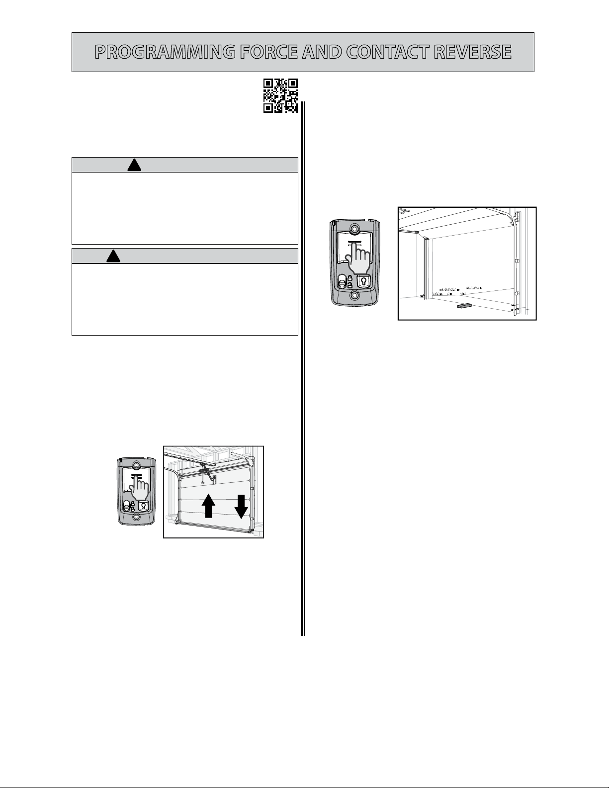
1. Press and release the Wall Control button and
allow the garage door to travel and stop at the
DOWN limit.
2. Press and release the wall control button and
allow the garage door to travel and stop at the
UP limit.
Contact Reverse Test
The limit and Force settings MUST BE COMPLETED
NOTE:
before performing the Contact Reverse Test.
1. With the garage door open, lay a 2 X 4 board
at on the oor at the center of the door
opening.
2. Close the garage door using the wall control.
• When the door contacts the board, it should
stop and reverse direction within 2 seconds to
the full open position.
• The long LED light on the powerhead will begin
to ash RED with the reversal of the door.
• Remove the 2” x 4” board and operate the
opener with the wall control again. This cycle
will clear the ashing red LEDs.
Force Control Adjustments
Force settings are programmed from the factory to
remain within safe parameters. These should not
require adjustments. However, certain circumstances
may require adjustment. See section 4 Maintenance
and Adjustments for detailed instructions pertaining
to the adjustment of force controls.
Contact Reverse Adjustment
If the door stops before contacting the board or if it
does not reverse direction to fully open after contact
with the board, it may be due to an improperly set
DOWN limit. Verify settings by:
1. Repeat the “Down Travel Limit” section to make
certain the door is closing tight against the oor.
2. Repeat the “Force Control” section on the left to
set force limits.
3. Repeat the “Contact Reverse Test” above.
Repeat this process as needed until the door passes
the Contact Reverse Test. For further help, refer to
the “Maintenance and Adjustment” section/Regular
Maintenance.
10
Page 11

PROGRAMMING ADDITIONAL REMOTE CONTROLS
THE REMOTE CONTROLS INCLUDED WITH
THIS OPENER HAVE BEEN
PROGRAMMED AT THE FACTORY FOR YOUR
CONVENIENCE.
NOTE: The following instructions are for remote control transmitters
purchased separately in addition to those provided with this opener,
but can also be used if any remote(s) may require re-programming.
NOTE: Each programming step has a 30 second time limit for
completion after the function is initiated. After 30 seconds, two
LED’s will illuminate RED indicating time has expired and the step
must be re-started. Restart the step as many times as necessary to
complete the programming.
NOTE: Do not hold remote too close to the powerhead when
programming remote buttons.
NOTE: Each button on each remote must be programmed
separately, following these steps.
1. Remove the battery’s protective lm from the
remote by pulling straight down.
1. Activate Remote
2. Enter Programming Mode
Solid Blue
PRESS FOR
2 SECONDS
& RELEASE
2. Press and hold the SET/PRGM button on the
opener for two seconds.
• The ROUND LED will turn BLUE.
• The LONG LED will then ash PURPLE.
3. Stand at least 5 feet away from opener and
slowly press and release the desired button on
the remote two times.
• Both opener LEDs will ash and turn o
indicating the remote has been programmed.
4. Press the desired remote button again.
• The opener should run.
To program the same remote for other garage door
openers, repeat the steps above using one of the other
remaining remote buttons.
REPEAT STEPS 1 TO 4 FOR EACH OPENER AND
REMOTE
NOTE:
or lightly. If the LEDs do not go o , press the remote button
several more times to achieve con rmation.
It is possible to press the remote button too quickly
Flashing Purple
3. Press Remote Button Twice
Flashing
4. Test Remote
BASIC PROGRAMMING IS COMPLETE AND YOUR GARAGE
DOOR OPENER IS READY TO USE.
See back of this manual to erase remote devices from
memory.
11
Page 12

IMPORTANT SAFETY INSTRUCTIONS
WARNING
!
To reduce the risk of severe injury or death,
read and follow all instructions.
1. NEVER let children operate or play with the door controls.
2. Keep remote away from children.
3. ALWAYS keep the moving door in sight and away from people and objects until door is completely closed. NO ONE
SHOULD CROSS THE PATH OF THE MOVING DOOR.
4. NEVER GO UNDER A STOPPED, PARTIALLY OPEN DOOR.
5. Test opener monthly. The door MUST reverse on contact with a 1-1/2” high object (or 2” x 4” board laid at) at the center
of the doorway on the oor. After adjusting either the force or limit of travel, retest door opener. Failure to adjust the
opener properly may cause severe injury or death.
6. When possible, use emergency release only when door is closed. Use caution when using this release with the door
open. Weak or broken springs are capable of increasing the rate of door closing and increasing the risk of severe injury or
death.
7. KEEP DOORS PROPERLY BALANCED. See your garage door Owner’s Manual. An improperly balanced door increases the
risk of severe injury or death. Have a trained door system technician make repairs to cables, spring assemblies, and other
hardware.
SAVE THESE INSTRUCTIONS
IMPORTANTES CONSIGNES DE SÉCURITÉ
!
AVERTISSEMENT
Pour réduire le risque de blessures graves
voire mortelles, lire et comprendre toutes les
instructions.
1. NE JAMAIS permettre aux enfants d’actionner ou de jouer avec les commandes de la porte.
2. Tenir les télécommandes hors de la portée des enfants.
3. TOUJOURS garder en vue la porte en mouvement et tenir à l’écart toute personne ou objet jusqu’à ce que la porte soit
totalement fermée. PERSONNE NE DOIT TRAVERSER LA TRAJECTOIRE D’UNE PORTE EN MOUVEMENT.
4. NE JAMAIS PASSER SOUS UNE PORTE À L’ARRÊT PARTIELLEMENT OUVERTE.
5. Tester l’ouvre-porte une fois par mois. La porte de garage DOIT inverser sa course au contact d’un objet de 4 cm (planche
de 5 sur 10 cm) posé à plat sur le sol au centre de l’ouverture de la porte. Après avoir réglé la force ou la limite de la
course, retenter l’ouvre-porte de garage. Un mauvais réglage de l’ouvre-porte peut entraîner des blessures graves voire
mortelles
6. Utiliser, dans la mesure du possible le déclenchement d’urgence uniquement lorsque la porte est fermée. Utiliser le
déclenchement d’urgence avec prudence lorsque la porte est ouverte. Des ressorts faibles ou brisés peuvent faire
descendre la porte rapidement ce qui peut entraîner des blessures graves voire mortelles.
7. VEILLER À CE QUE LA PORTE SOIT CORRECTEMENT ÉQUILIBRÉE. Consulter le manuel du propriétaire de la porte de
garage. Une porte déséquilibrée pourrait entraîner de graves blessures voire mortelles. Demander à un technicien
spécialisé en système de portes de se charger des réparations des câbles, des ressorts et de toute autre quincaillerie.
CONSERVER CES INSTRUCTIONS
!
WARNING
Opener is equipped with grounded electrical plug for your protection, and
only ts grounded electrical outlets. DO NOT alter plug in any way! If your
have no grounded outlets, have one installed by a licensed electrician.
Opener must be properly grounded to prevent personal injury and equipment
damage. NEVER USE AN EXTENSION CORD! Check local building codes for
any requirement that you must have a permanent hard-wired connection.
Permanent hard-wired connections must be performed by a licensed electrician
using proper tools and instructions.
L’opérateur, qui est équipé d’une prise électrique mise à la terre pour votre
protection est compatible uniquement avec des prises électriques mises à
la terre. NE PAS modi er la che dune quelconque manière. Si vous n’avez pas
de prises mises à la terre, faites-en installer par un électricien agréé. L’opérateur
doit être correctement mis à la terre pour éviter les blessures corporelles et des
dommages matériels. NE JAMAIS UTILISER DE RALLONGE! Véri ez les codes
locaux des bâtiments pour connexions câblées permanente. Les connexions
câblées permanentes doivent être e ectuées par un électricien agréé qui se
servira d’outils appropriés et respectera les consignes.
!
AVERTISSEMENT
12
!
• Garage door hardware (springs, cables, brackets, pulleys, etc.) are under
extreme pressure and tension.
• DO NOT attempt to repair or adjust door springs or any hardware, and
DO NOT OPERATE garage door automatically or manually if door is
improperly balanced or springs are broken.
• CONTACT A TRAINED DOOR SYSTEM TECHNICIAN.
WARNING
!
• La quincaillerie de la porte de garage (ressorts, câbles, supports, poulies,
etc.) sont sous des pressions et des tensions extrêmes.
• NE PAS réparer ni régler les ressorts de la porte ou toute autre pièce
de quincaillerie et NE PAS ACTIONNER la porte manuellement ou
automatiquement si elle n’est pas correctement équilibrée ou si des ressorts
sont cassés.
• CONTACTEZ UN TECHNICIEN SPÉCIALISÉ EN SYSTÈME DE PORTES
AVERTISSEMENT
Page 13

4
DOOR
Engage
Disengage
To disengage carriage from
the turnbuckle, pull handle
down and to the rear.
To engage carriage to
the turnbuckle, pull handle
forward and up.
Release shown in
engaged position
MAINTENANCE & ADJUSTMENTS
!
WARNING
Use of any other wall control can cause unexpected operation of the door and
loss of lighting feature. Locate wall console within sight of the door but far
enough from door to prevent contacting it while operating the console. Control
must be at least 5 feet above the oor to prevent small children from operating
it.
Regular Maintenance
Basic monthly maintenance tasks include:
• Contact Reverse Test
• Lubricate door hardware
• Safe-T-Beam® System check
• Door balance
• Remote Battery Replacement (As needed)
• Light Bulb Replacement (As needed)
• Chain/Belt Tension
A. Contact Reverse Test
See page 10.
B. Lubricate Door Hardware
Inspect door rollers and hinges and lubricate as needed using a
light weight general purpose grease.
D. Door Balance (Spring Tension)
Perform the check as follows:
• With the door closed, pull manual emergency release handle
DOWN and away from door and let go to disengage the carriage
from the drive chain or belt (see illustration).
!
L’utilisation d ’une au tre commande murale p ourrait produire d es résultats inattendus de la
porte ainsi que le dysfonc tionnement de l’éclairage. Localisez la console murale en vue de
la porte et su samment loin d e la porte pour éviter tout contact pen dant l’utilisation de la
console. L a commande doit être à une hauteur minimale de 1,5 m au-dessus du sol a n que le s
jeunes enfants ne puissent pas l’atteind re.
AVERTISSEMENT
C. Safe-T-Beam® (STB) System Check
Check that both the RED and GREEN LEDs are ON steady. This indicates
the system is working properly. If both LEDs are not ON steady, check
the appropriate items below:
• STB red LED ashes.
– Check for obstruction.
– Check alignment. (See page 16)
– Verify wire routing from STBs to STB connection in powerhead
– Check for signal interference from another Safe-T-Beam® unit
(for multiple door installations).
• No STB red or green LED displayed.
– Check wiring and wire connections
If system appears to be working properly, perform check as follows:
1. Start the door closing.
2. Pass an object through the beam. The door should stop and
reverse to the fully open position.
• Raise and lower the door
manually — it should move
freely and smoothly.
• Raise door manually about
3’ to 4’ feet and let go.
– Door should remain stationary or move very slowly.
– If door moves quickly, CONTACT A TRAINED DOOR SYSTEM
TECHNICIAN to have your door springs serviced.
• Close the door.
• Place the carriage in the “engage” position (see illustration).
• Operate door using remote or wall control. The carriage will
reattach itself to the drive chain/belt.
DO NOT use release cord to pull door.
E. Remote Battery Replacement (As needed)
Remote Battery Replacement (1-button)
Replace remote battery with a CR2032 coin cell battery.
1. Slide the battery cover o (it’s the lower half of the remotes case) by pressing on the case just below
the indentation at the top of the cover and sliding it down. Alternately, insert a coin or small washer into
the indentation in the front of the case and pry to unlatch the battery cover in order to slide it o .
2. Slide out the old battery and slide in the new. Be sure positive side (+) is UP.
3. Slide the battery cover on until it snaps into place.
Remote Battery Replacement
Replace remote battery with a CR2032 coin cell battery.
1. Open remote case using a washer or coin that ts into the slot on the top of the remote.
2. Replace battery.
3. Align components and snap case closed.
Be sure positive side (+) is UP.
(3-button)
13
Page 14

Pull light covers away from powerhead
Push down tabs
Pull light cover away from powerhead
1/4”
MAINTENANCE & ADJUSTMENTS
F. Light Bulb Replacement
!
WARNING
• Use extreme caution when working from a ladder or step
stool or serious injury can occur.
• When replacing light cover, make sure wires are not pinched
or near moving parts.
• Use only properly rated incandescent, LED or CFL light bulbs.
• DO NOT use bulbs with a rating greater than 60 Watts.
• Use A19 size light bulbs. DO NOT use bulbs having a short
neck.
Changing Light Bulbs
1. Disconnect power to door opener.
Open powerhead light cover(s) by pressing down on
upper locking tabs.
• Replace old light bulb(s) with new.
• Use 60 Watt MAX. incandescent bulbs or the CFL or LED
equivalent.
• Close powerhead light cover(s).
2. Reconnect power to door opener.
• Test light operation.
NOTE: Use of LED bulbs may reduce the range of your remote
controls. Visit www.GenieCompany.com for more information
and recommendations for LED bulbs.
NOTE: SilentMax Connect™ models require a minimum 40
Watt or equivalent bulb, 60 watt maximum.
!
AVERTISSEMENT
• Faire particulièrement attention lors de travaux e ectués
depuis une échelle ou en escabeau.
• En referment le couvercle de l’éclairage, s’assurer que les ls
ne sont ni coincés ni près des pièces mobiles.
• Utilisez uniquement incandescence correctement classé, LED
ou des ampoules uocompactes.
• NE PAS utiliser des ampoules avec une note supérieure à 60
Watts
• Utilisez A19 ampoules de taille. NE PAS utiliser des ampoules
ayant un cou court.
1 Light Models
2 Light Models
* Genie LED light bulbs are designed to reduce or
eliminate reduced remote range issues caused by
common LED bulbs. They also o er better product
life by making them resistant to vibration caused
by the opener, and cold or damp weather. See
website for details at www.GenieCompany.com.
G. Chain/Belt Tension
If excessive chain/belt sag is noticed below the rail:
1. Open the door until carriage is about mid travel and stop.
2. Disengage the carriage and manually close the door.
3. Loosen nuts on turnbuckle using 7/16” wrenches.
4. Rotate turnbuckle counter-clockwise until slack is removed from
chain/belt.
5. When measured on the opposite side of the rail from the
turnbuckle, a properly adjusted chain will have a 1/4” gap to the
bottom of the rail.
6. Tighten nuts to secure turnbuckle.
7. Be sure that chain/belt is not twisted or bound.
8. Manually open door to re-engage carriage to turnbuckle.
14
Page 15

MAINTENANCE & ADJUSTMENTS
H. Adjust Carriage for (optional) Emergency Release System
The carriage on this opener can be adjusted to work with the Emergency
Release Cable Lock System (available at your local Genie® Retailer).
1. Operate door to mid position.
2. Pull emergency release cord and manually close door.
3. Make sure carriage latch is in the upright (engaged)
position.
4. Remove (2) 5/16” machine screws and cap.
5. Pull spring assembly out and reverse direction.
6. Install cap and machine screws.
Emergency Release cable can now be assembled to the
carriage assembly.
I. Adjustment Guides
!
WARNING
TO AVOID INJURY OR DAMAGE
• NEVER adjust the force settings to adjust for damage,
including an unbalanced door, binding door track or
broken spring.
• Perform a CONTACT REVERSE TEST monthly. See page 10.
Pour éviter les blessures ou des dommages
• NE JAMAIS régler la force pour compenser des dommages,
y compris une porte mal équilibrée, un rail de porte coinçant
ou des ressorts cassés.
• Tous les mois, EFFECTUEZ LE TEST D’INVERSION AU CONTACT.
Voir page 10.
Force Settings
Force settings are pre-programmed at the factory and applied
during the Open/Closed Limit settings steps (see page 8). For
normal use, these settings should not need adjustments with this unit.
Conditions possibly requiring adjustments are:
1. Doors with very sti weather seals.
2. Doors that start down, STOP, and reverse before closing.
3. Doors that start up, but STOP before they completely open.
Rail, Chain, & Door
Arms not shown for
clarity
DOOR
!
AVERTISSEMENT
Press and hold both up and
down arrow buttons until
round LED turns RED, release
button. BLUE LED will ash 3
times.
LEDs will now display current UP force setting (See chart).
Press either arrow button until
desired UP force setting is
reached (see chart).
Once setting is chosen, press
and release. This will lock the
UP force setting.
LEDs will now show current DOWN force setting. (See Chart).
Press either arrow button until
desired DOWN force setting is
reached. (See chart).
Once setting is chosen, press
and release. This will lock the
DOWN force setting.
The LEDs will now turn BLUE then o . This con rms
that both force setting have been reset and unit is
ready for normal operation.
Repeat “Learn Force Limits and Contact Reverse Test” page 10
RED
OFF
See Chart
See Chart
BLUE
BLUE
OFF
BLUE
Flashes
3 Times
OFF
J. Resetting Travel Limits
See pages 8-9 to reset travel limits. Force setting and contact reverse test must be performed in the event of a travel limit change.
15
Page 16

LOCATING SAFE-T-BEAM® PAIRS
Transmitter (RED LED) and Receiver (GREEN LED)
WARNING
AVERTISSEMENT
CHOC ÉLECTRIQUE
OUVERTURE DE COUVERTURE
PEUT PROVOQUER
CHOC ÉLECTRIQUE.
Coupez l'alimentation du
premier match avant de retirer
le couvercle.
BBU
(optional)
Light
Light (2 Light models only)
Red
Black
MAINTENANCE & ADJUSTMENTS
Multiple Garage Doors
•
NEVER position Safe-T-Beam® modules where signals will cross.
• Place the Transmitter (Red LED) Safe-T-Beams on adjacent doors
facing in opposite directions.
NOTE: Direct sunlight creates interference with Safe-T-Beam
Receiver (Green LED). STB modules CAN be positioned further
away from the door opening if necessary to avoid sunlight
but no further o the wall to maintain alignment with the
Transmitter (Red LED) module.
Single Garage Door
• Determine which side of the garage receives direct sunlight.
• Position the Transmitter (Red LED) on the direct sunlight side.
NOTE: Only use Safe-T-Beams® that are included with this opener. DO NOT use other
brands or types of photocells on this opener.
®
WIRE DIAGRAM
16
Page 17

Visit www.genicompany.com or call Customer Service at 1-800-35-GENIE.
Need help or have questions? DO NOT RETURN to the store.
5
TROUBLESHOOTING
PROBLEM: WHAT TO DO:
Opener does NOT
operate when wall
control is pressed.
Opener runs, but
door does not
move.
Opener works from
wall control, but
NOT from remote.
Remote has less
than 25 feet
operating range or
no operation.
Door starts down,
then STOPS and
goes back up.
OR
Safe-T-Beam
®
System malfunction.
Door starts down,
then STOPS before
it is closed.
OR Door will only
open.
Door starts up, but
STOPS before it is
completely open.
Door will only run
closed.
Door opener starts
for no reason.
Noisy operation.
Door opener runs
slow.
• Turn Sure-Lock™ OFF See page 6.
• Check power source.
– Plug a lamp into outlet used for powerhead. If lamp works, power source is OK.
– If not, check fuse or circuit breaker.
• If power is OK,
– Check connections at powerhead terminals and at wall console.
• Check for reversed, broken or cut wires. Staples can cut insulation and short wires. Repair or replace.
• Make sure carriage is engaged with chain/belt turnbuckle. Refer to installation
poster or download poster from www.GenieCompany.com
• Check to make sure chain/belt is not broken or o its pulley.
• Check all remotes.
• Replace remote battery. See page 13.
• Program remotes to powerhead. See page 11.
• Relocate remote inside car and /or point remote at garage door.
• Replace battery. See page 13.
• Reposition door opener antenna.
• Eliminate possible competing signals (radio, etc.).
• LED bulbs may be interfering with remote signal. See page 14.
• If a NEW installation, check Door Arm position. Refer to Installation poster or download poster
from www.GenieCompany.com.
• If NEW Installation, make sure ONLY the Safe-T-Beams® that came with this opener are installed.
• Check if limits are properly set. See pages 8-9. Adjust limits as needed.
• Check if Safe-T- Beam® red LED is ashing. See page 16, Safe-T-Beam® system check.
• Check Safe-T-Beam® system for beam obstruction or misalignment of lenses. See page 16, Safe-T-Beam®system.
• Check garage door for binding.
• If an operational problem exists, and opener will not close, the opener can be forced to close as follows: Press
and hold the wall control button until door is completely closed.
• Check for interference from adjacent Safe-T-Beam® units. See page 16.
• Contact Genie at 1-800-35-GENIE.
• Check Safe-T- Beam®wire connection at powerhead and at STBs. See page 16, Safe-T-Beam® system check.
• Check if limits are properly set. See pages 8-9. Adjust limits as needed.
• Check CONTACT REVERSE. See page 10.
• Check garage door for binding. See maintenance and adjustment. Page 13.
• Check closing “FORCE” control. See page 10, or Force settings. Page 15.
• Check if limits are properly set. See pages 8-9. Adjust limits as needed.
• Be sure door, opener, springs are in good repair, properly lubricated and balanced.
• Check closing/opening “FORCE” control. See page 10, or Force settings Page 15.
• If you suspect a problem with the garage door hardware or springs, visit www.GenieCompany.com
and use the “dealer locater” to hire a local door service professional.
NEVER try to repair door hardware or springs yourself.
• Turn Sure-Lock™ OFF See page 6.
• Check if limits are properly set. See pages 8-9.
• Check door balance, condition, and door spring.
• Check opening “FORCE” control. See page 10, or Force settings. Page 15.
• If you suspect a problem with the garage door hardware or springs, visit www.GenieCompany.com
and use the “dealer locater” to hire a local door service professional.
NEVER try to repair door hardware or springs yourself.
• Button stuck on wall control or remote.
• Was remote lost or stolen? Erase all remotes from powerhead memory and program new remotes. See page 20.
• Be sure all door fasteners are tight.
• Be sure garage door is in good repair, properly lubricated and balanced.
• Be sure opener is in good repair.
• Check operating condition of door. Door may need professional repair/adjustment.
• Is this opener installed on a one-piece door? This opener is not designed to operate a one-piece door.
17
Page 18

POWERHEAD LEDS
Powerhead LED
Round LED Long LED
OFF OFF
ON/RED/
STEADY
ON/RED/
FLASHING
ON/BLUE/
FLASHING
TROUBLESHOOTING
Possible Problem
Normal operation. None required.
No response from unit.
ON/RED/
STEADY
ON/RED/
FLASHING
OFF Remote NOT programmed. Program remote, see page 11.
Limits NOT set properly. Re-program limits, see pages 8-9.
Program error. Unplug unit, wait 5 seconds, plug in.
Component failure. Contact a trained door system technician.
Check power supply.
Contact a trained door system professional.
Solution
ON/PURPLE/
FLASHING
ON/RED/
FLASHING
OFF
OFF
ON/PURPLE/
STEADY
OFF
ON/PURPLE/
FLASHING
ON/GREEN
STEADY
ON/GREEN
FLASHING
ON/YELLOW
FLASHING
ON/RED TO YELLOW
FLASHING
ON/WHITE STEADY ON/WHITE STEADY Battery Backup in Operation
ON/RED TO YELLOW
OFF Remote NOT programmed. Program remote, see page 11.
Safe-T-Beam® physical obstruction. Remote obstruction, recheck unit.
OFF
Safe-T-Beam® signal interference.
ON/RED/
FLASHING
ON/RED/
STEADY
ON/PURPLE/
STEADY
ON/BLUE/
FLASHING
ON/PURPLE/
FLASHING
ON/GREEN
STEADY
ON/GREEN
FLASHING
ON/YELLOW
FLASHING
FLASHING
Door contact in UP or DOWN travel. Remove obstruction.
Door component failure detected.
Thermal cutout.
Component error. Contact a trained door system technician.
Door will not open.
Radio receiver error.
OK=Charged, Battery Backup
Discharging, Battery Backup
Charging, Battery Backup
Dead Battery, Battery Backup
Check alignment of Safe-T-Beam® pair and
nearest other Safe-T-Beam® pair, see page 16.
Check door spring, track, rollers, hinges and
xtures.
DO NOT unplug unit.
Wait until LED clears before operating.
Check Sure-Lock™. Sure-Lock™ should be OFF for
normal operation (see page 6).
Unplug the unit. Wait 5 seconds and plug the unit
back in. If problems persist, contact a trained door
system technician.
None Required
Power is out. Battery in use.
None Required
Allow to charge 48 hours. If charging fails,
Replace Battery.
No Fault. Courtesy light while in battery
backup mode. Light will turn o after 4
minutes.
18
Page 19

WHITE(+)
TO PREVENT POSSIBLE
SERIOUS INJURY or DEATH
from electrocution AND REDUCE RISK of FIRE
— Disconnect ALL electric power sources and battery
power BEFORE performing ANY service or maintenance.
Install only in DRY locations - NOT INTENDED FOR OUTDOOR USE.
Use only 12V, 5AH, SLA replacment battery
(P/N 111658.0002.S).
CAUTION
Installer uniquement dans des endroits secs—NE DOIT PAS ÊTRE
UTILISÉ À L'EXTÉRIEUR.
Utiliser uniquement une pile de remplacement de 12V, 5AH, SLA
(réf. 111658.0002.S).
POUR ÉVITER LES BLESSURES
GRAVES VOIRE MORTELLE PAR
ÉLECTROCUATION POUR RÉDUIRE ES LES RISQUES
D'INCENDIE
—Débrancher toutes les sources d’alimentation électriques et
la pile avant d'eectuer des opérations de réparation ou
d'entretien.
ATTENTION
6
GENIE® BATTERY BACKUP INSTALLATION
Battery backup devices from other manufacturers will not operate with this opener.
Use only Genie Battery Backup type battery that was provided. Genie P/N 111658-0002
Installing Genie Battery Backup
For units that included with optional battery backup (BBU)
1. Unplug powerhead from power source.
2. Tilt BBU approximately 45 and lower into slots in the top rear of the
powerhead.
3. Fasten to powerhead with 2 supplied self tapping screws.
NOTE: There are no holes in rear cover. Self Tapping screws will self tap through cover.
4. Plug battery harness into plug located at the top of the powerhead.
5. Reconnect powerhead to power source.
45
See page 18 for
Condition LED’s
That will illuminate once
Genie Battery Backup is
operational.
Both LEDs will signal
solid GREEN under
normal, fully charged,
operation.
Testing The Genie Battery Backup
NOTE: It is recommended that the battery backup be allowed to charge for 24 to 48 hours prior to testing. Initially, the opener may not
operate from the battery backup mode if battery is not fully charged.
1. Run the opener using the wall control or remote to ensure it is working properly.
2. Turn o power to opener by unplugging from outlet or turning o breaker.
3. Press wall control or remote control. Opener will run at a slower speed than normal.
NOTE: See troubleshooting guide (pg. 18) in this manual if any of the steps above fail.
Work light will not operate while in battery backup mode. (Courtesy white LED’s will
illuminate.)
4. After successful test, reconnect powerhead to power source.
Replacing The Battery in the Genie Battery Backup
Proper care should be used when handling a battery. Eye protection should be worn.
NOTE DO NOT reverse polarity (+) and (-) as this will damage the powerhead.
1. Unplug powerhead from power source.
2. Unplug battery backup from harness
connection.
3. Remove both mounting screws from
rear of battery backup.
4. Detach battery backup from
back of opener by tilting the BBU
approximately 45 degrees and lifting
up towards the ceiling.
5. Remove 4 screws from battery hold
down bracket.
6. Remove battery.
7. Disconnect harness wires from the (+)
and (-) terminals.
8. Replace in reverse order
NOTE: Allow 24-48 hours to charge battery
before testing.
9. Test as noted above.
Completed Assembly
19
Page 20

7
OPTIONAL PROGRAMMING & ACCESSORIES
CLEARING MEMORY OF REMOTES
Clearing memory of remotes from the powerhead
NOTE:
will clear ALL programmed remotes, wireless keypads and
vehicle transmitters. The opener will no longer recognize
any signal from any remote device, including a missing
remote device.
All remaining (or recovered) remotes, vehicles and
wireless keypads MUST be reprogrammed.
NOTE:
The garage door opener will operate normally
using the wall console.
1. Press and hold the SET/PRGM button on the
opener for two seconds.
• The ROUND LED will turn BLUE.
• The ROUND LED will then ash PURPLE.
2. Press and hold the UP & DOWN buttons at the
same time until both LEDs turn o .
• Both opener LEDs will ash and turn o
indicating that all remotes have been erased.
2. Press and Hold + & - Buttons
Flashing
Blue
Release when LEDs turn o
3. Press any remote button.
• The opener should NOT run.
To deprogram the same remote for other garage door
openers, repeat the steps above using one of the other
remaining remote buttons.
1. Enter Programming Mode
Solid Blue
PRESS
&
RELEASE
OFF
3. Test Remote
20
Flashing Purple
Page 21

VEHICLE PROGRAMMING
Programming HomeLink® System Programming Car2U® System
Step 1 Clear HomeLink
Clear HomeLink by pressing and
holding down the rst and third buttons
until the indicator on the HomeLink blinks
slow and then fast for 20 seconds; then
release both buttons.
NOTE: Clearing the HomeLink will remove all previously
programmed garage door openers.
Step 2 Train HomeLink to the Genie Remote
Choose the button on the HomeLink that will be used to open the door.
NOTE:
Hold the Genie Remote two inches from the HomeLink button.
Hold down the Genie remote button. While holding, press and hold the
chosen HomeLink button.
Hold down both buttons until the indicator on the HomeLink blinks slow
then fast. Once it blinks, release both buttons.
Step 3 Program HomeLink to the Genie Opener
A. Press and hold the PROGRAM button on the opener until the round
blue LED is ON. Release the button. The long purple LED will begin
ashing.
Step 1 Clear Car2U to default settings
The default setting for the Car2U system is:
• Button 1 = Genie® Manufactured Openers
• Button 2 = LiftMaster® Manufactured Openers
• Button 3 = Wayne Dalton® Manufactured Openers
A. Press and hold buttons 1 and 3 for 20 seconds or until all three LEDs
begin to ash.
B. Release both buttons. The Car2U system is now set to the Factory
Default settings
NOTE:
Clearing the Car2U remote will remove all previously programmed
garage door openers.
Step 2 Program Car2U to the Genie Opener
A. Press and hold the PROGRAM button on the opener until the round
blue LED is ON—release the button. The long purple LED will begin
ashing.
Flashing Purple
B. Press the designated Genie Car2U button for two seconds and release.
Press that same button again for two seconds and release. The long LED
will ash blue and then turn o .
Flashing Purple
B. Press the chosen HomeLink button for two seconds and release. Press
that same button again for two seconds and release. The long LED
will ash blue and then turn o .
C. Press the HomeLink button a few more times until door moves.
NOTE:
For additional instructions, see the motor vehicle manual,
www.homelink.com or visit www.GenieCompany.com
C. Press the Car2U button a few times more until door moves.
Step 3 Changing Factory Default Button for a Genie Opener
A. Press and hold buttons 1 & 3 for ONE SECOND and release— all three
LEDs will light solid red.
B. Press and hold the button (2 or 3) to change it to Genie —the
corresponding LED will ash. While continuing to hold that button,
press and release button 1. Press and release button 1 again.
C. Release the button being held in step B and wait for the LED to stop
ashing. This button is now set for Genie. Repeat Step 2 for second
Genie Opener.
NOTE:
For additional instructions see the motor vehicle manual,
learcar2u.com or visit www.GenieCompany.com
21
Page 22

WIRELESS KEYPAD PROGRAMMING
TAB
Keypad
Up/DownKey
(enter)
ProgramKey
LED
LEDO
LEDOn
LEDFlashing
KeypadO
KeypadOn KeypadFlashing
Tip: Program Keypad before mounting.
Keypad Overview:
Activate keypad by opening battery
compartment and pull protective
tab. Reinstall compartment door to
begin programming.
STEP 2B) PROGRAMMING THE KEYPAD FOR MULTIPLE OPENERS
(UP TO 3)
Program the keypad with a Personal Identi cation Number
(PIN) as described in step 1. Then follow these additional steps.
1. Ensure number pad back lighting is o .
2. Enter PIN as programmed in STEP 1.
3. Press PROGRAM key twice. LED will blink once per second.
4. Enter total number of openers that keypad will be
operating. (2 or 3).
5. Press PROGRAM key once. LED will blink twice and shut o .
• NOTE: Only one PIN number can be used.
• The keypad is now programmed with a PIN number and
set up for multi opener operation. Keypad is now ready to
program to multiple Genie® Intellicode® garage door openers.
• If LED did not blink twice and shut o , please see RESETTING
THE KEYPAD (FACTORY DEFAULT) section.
PROGRAMMING THE KEYPAD TO MULTIPLE OPENERS (UP TO 3)
1. Place desired garage door opener (1, 2, or 3) into
PROGRAMMING MODE as illustrated in the section below.
2. Ensure number pad back lighting is o .
3. Enter the PIN number on keypad.
4. Press the UP/DOWN key once.
5. Press the number of the desired door (1,2 or 3).
6. Press the UP/DOWN key 3-4 times slowly until garage door
opener operates.
• Repeat steps 1 through 6 to program second and third
openers.
• This completes programming of multiple doors. See STEP 3
MULTI-DOOR OPERATION for further instruction.
22
STEP 1) PROGRAMMING A PIN NUMBER
Program the keypad for the rst time* with a Personal
Identi cation Number (PIN). This PIN must be 3 to 8 digits.
1. Ensure number pad back lighting is o .
2. Press 3-5-7 in sequence.
3. Press PROGRAM key. LED will blink once per second.
4. Enter a PIN number (3-8 digits).
5. Press PROGRAM key. LED will blink twice and shut o .
• The keypad is now programmed with a PIN number and
ready to program to Genie® Intellicode® garage door
opener(s).
• See STEP 2A to program 1 Genie® Opener.
• See STEP 2B PROGRAMMING FOR MULTIPLE OPENERS if
using keypad to operate up to 3 doors.
• If LED did not blink twice and shut o , please see
RESETTING THE KEYPAD (FACTORY DEFAULT) section.
STEP 2A) PROGRAMMING THE KEYPAD TO 1 OPENER
1. Place garage door opener into PROGRAMMING MODE.
2. Ensure number pad back lighting is o .
3. Enter the PIN number on keypad.
4. Press the UP/DOWN key 3 to 4 times slowly until garage
door opener operates.
• This completes the programming of a single door. See
STEP 3 SINGLE DOOR OPERATION for further instruction.
PUTTING OPENER INTO PROGRAMMING MODE:
1. Press and hold the program button until the round LED
turns blue, then release.
2. The round LED will go out and the long LED will begin
ashing purple.
3. Return to STEP 2A or 2B.
Solid Blue
PRESS
&
RELEASE
Flashing Purple
NOTE: The openers LEARN LED will time out in 30 seconds.
Programming must be completed within 30 seconds.
* RESETTING THE KEYPAD (FACTORY DEFAULT):
If the keypad has already been programmed or at any time the
programming should be erased and started from the factory
default, follow these steps.
1. Ensure that number pad back lighting is o .
2. Press and hold the PROGRAM and UP/DOWN Keys
together for approximately 5 seconds.
3. The LED will ash twice and all lights will go out indicating
the keypad has been reset.
4. Start at STEP 1 to program a new PIN number.
Page 23

WIRELESS KEYPAD PROGRAMMING
Wall
1/8"
Screw
head gap
STEP 3) OPERATING THE KEYPAD WITH THE OPENER(S)
Single Door Operation:
1. Ensure number pad back lighting is o .
2. Enter PIN number.
3. Press the UP/DOWN key.
4. Opener will operate.
Multi-Door Operation:
1. Ensure number pad back lighting is o .
2. Enter PIN number.
3. Press the UP/DOWN key.
4. Press number key corresponding with desired door (1, 2,
or 3).
5. Desired opener will operate.
NOTE: Keypad will remain active for 15 seconds after a successful
entry is made. During this 15 seconds ANY key will operate the
opener.
STEP 4) MOUNTING THE KEYPAD
Keypad MUST be mounted within sight of the garage door(s)
at least 5 feet above oor and clear of any moving door parts.
• Programming will not be lost during battery change.
1. Remove battery cover and batteries.
2. Drill a 3/32” pilot hole for the top mounting screw.
3. Install included screw into pilot hole, leaving 1/8” gap
between the screw head and wall.
4. Hook the slotted mount on back of keypad over the screw.
REPLACING BATTERIES
If the keypad back-lighting fails to operate, Batteries may
require replacement.
• Programming will not be lost during battery change.
1. Remove battery cover and batteries.
2. Replace batteries with same type alkaline (AAA) and
check for proper direction of (+) and (-) terminals.
Rechargeable batteries are NOT recommended.
ADDITIONAL (OPTIONAL) PROGRAMMING:
Changing an Existing PIN:
1. Enter current PIN
2. Press PROGRAM key once.
3. Enter new PIN.
4. Press PROGRAM key once.
• Original PIN will no longer operate keypad or opener.
Setting a Temporary PIN:
A temporary PIN allows temporary access to the garage by,
normally unauthorized, personnel such as repairmen or
neighbor.
1. Enter current PIN.
2. Press PROGRAM key 3 times.
3. Enter a temporary PIN (3 to 8 digits)
4. Press PROGRAM key once.
• The Temporary PIN will operate garage door opener
until the original PIN is used. Use of the original PIN will
delete temporary PIN.
Scan this code with a QR code reader
app on a smart device to view a video
of these instructions.
or visit www.GenieCompany.com
5. Mark and drill a 3/32” pilot hole for the bottom screw and
secure keypad to the wall. (Do not over-tighten).
6. Reinstall batteries.
FCC Part 15.21 Statement:
Changes or modi cations not expressly approved by the
party responsible for compliance could void the user’s
authority to operate the equipment.
FCC / IC Statement:
This device complies with FCC Part 15 and Industry Canada
licence-exempt RSS standard(s). Operation is subject to
the following two conditions: (1) this device may not cause
harmful interference, and (2) this device must accept any
interference received, including interference that may
cause undesired operation of the device.
Le présent appareil est conforme aux CNR d’Industrie
Canada applicables aux appareils radio exempts de
licence. L’exploitation est autorisée aux deux conditions
suivantes : (1) l’appareil ne doit pas produire de
brouillage, et (2) l’utilisateur de l’appareil doit accepter
tout brouillage radioélectrique subi, même si le brouillage
est susceptible d’en compromettre le fonctionnement.
23
Page 24

8
ORANGE BAG
5/16" x 1-3/4"
Lag screw (x2)
1/4"- 20 - 3/4"
Self-drilling screw (x4)
Header bracket
Rail Strap
Turnbuckle
Bolt 5/16-18 x 2Nut 5/16-18 Serr.
Cotter Pin (x2)
Clevis Pin 5/16 x 1.75 (x2)
BLUE BAG
Cotter Pin (x2)Clevis Pin (x2) Screw Self Tap (x3)
Door Bracket
Bolt 3/8-.87 (x2)Nut 3/8-16 Hex (x2)Emergency Release Handle
Red Release Cord
Safe-T-Beam® Set
Safe- T- Beam®
sensor
Safe- T- Beam®
source
1/4" x 1-1/4"
Lag screw (x4)
GREEN BAG
#8 - 3/4"
Self-tapping
screw (x2)
1/4"x 3/4"
Insulated staple (x30)
5/16" x 1-3/4"
Lag screw (x2)
5/16"- 18 - 3/4"
Bolt (x2)
5/16"-18 Lock nut ,
serrated (x2)
CLEAR BAG
#6-18 x 3/8”
Self-Tap Screw (x2)
Cover, Belt Retainer
REPLACEMENT PARTS
3
9
7
2
6
A 39010R.S PARTS PK,MOUNTING,ORANGE ... 1
1 TURNBUCKLE ................................................... 1
2 PIN,CLEVIS,5/16 X 1-3/4 ................................. 2
3 COTTER,HAIRPIN,.0725 DI ............................... 2
4 BOLT,HH,PLD,5/16-18 X 2 ................................ 1
Item # Part Number Description....................................................Qty.
8
5 NUT,5/16-18 HX SERR FLG ...............................1
6 STRAP,RAIL,RECT .............................................1
7 SCR,SERR HWH,AB,1/4-14............................... 4
5
3 4
14
2
8 BRKT,HEADER,RECT RAIL .................................1
9 SCR,LAG,HWH,TPG,5/16”X1 ............................2
Item # Part Number Description....................................................Qty.
B 39011R.S PARTS PK,MOUNTING,BLUE .......... 1
1 TURNBUCKLE ................................................... 1
7
8
56
1
2 PIN,CLEVIS,5/16 X 1-3/4 ................................. 2
3 COTTER,HAIRPIN,.0725 DI ............................... 2
4 BOLT,HH,PLD,5/16-18 X 2 ................................ 1
5 NUT,5/16-18 HX SERR FLG ...............................1
6 STRAP,RAIL,RECT .............................................1
7 SCR,SERR HWH,AB,1/4-14............................... 4
8 BRKT,HEADER,RECT RAIL .................................1
9 SCR,LAG,HWH,TPG,5/16”X1 ............................2
3
Item # Part Number Description ........................................ Qty.
C 37105S.S PARTS PK, INSTALL, GREEN ........... 1
1 BOLT,HH,PLD,5/16-18 X 3 ................................ 2
2 NUT,5/16-18 HX SERR FLG ...............................2
4
3 SCR,LAG,HWH,TPG,5/16”X1 ............................2
4 PARTS PK,INSULATED STAP ............................. 30
24
2
1
12
3
2
1
Item # Part Number Description ........................................ Qty.
D 39012R.S PARTS PACK, CLEAR, BELT RETN .... 1
1 COVER,BELT RETAINER .....................................1
2 SCR,SF TP #6-18 X 3/8 .....................................2
Item # Part Number Description ........................................ Qty.
E 37220R Safe-T-Beam Set ............................. 1
1 XMTR ASSY,STB ............................................... 1
2 RCVR ASSY,STB ................................................1
3 SCR,#10-16 X 1.25 ........................................... 4
Page 25

or
A B C
D E F G H I J K
L
REPLACEMENT PARTS
Item # Description Qty.
A 5-pcs. Rail Assembly Complete (Chain) 1
5-pcs. Rail Assembly Complete (Belt) 1
B Sprocket Support Assembly (Chain) 1
Sprocket Support Assembly (Belt) 1
C Carriage Assembly 1
D Idler Pulley 1
E Chain Assembly (7Ft) 1
Belt Assembly(7Ft) 1
F Door Arm,Curved 1
G Door Arm,Straight 1
H Strap,Hanging,3/4 X 25. 2
I 90 Ft. Wire Spool 1
J Wall Console 1
K Wall Button 1
L Battery Backup Battery (Cover not included)
N/S Rail Extension Kit (Chain)
N/S Rail Extension Kit (Belt)
NOTE: The following kits will include all necessary harnesses, and/or hardware
required for reassembly and detailed assembly instructions.
Motor Assemblies PCB DC Controllers Light Sockets
Idler Pulley Assembly Transformer Assembly Chain & Belt Kits
Covers
25
Page 26

SINGLE BULB POWERHEAD
1
2
3
4
5
6
7
8
9
9
10
Item # Description QTY.
1 COVER,SINGLE BULB 1
2 LENS 1
3 MOTOR ASSEMBLY 1
4 SOCKET,LIGHT,30 DEG ANG 1
5 TRANSFORMER,120VAC 1
6 PCBA,DC CONTROLLER 1
7 POWER CORD,45” 1
8 SCR,M6-1 X 12 HWH THDF (3pk.) 1
9 SCR,HHD,SLTD,TAP,#8X5/1 (3pk) 2
10 Optical Encoder Assembly 1
Specify model number when ordering parts from Genie Customer Care.
26
Page 27

DUAL BULB POWERHEAD
1
2
3
4
5
6
7
8
9
9
2
4
10
11
Item # Description QTY.
1 COVER, DUAL BULB 1
2 LENS 2
3 MOTOR ASSEMBLY 1
4 SOCKET,ANGLED LIGHT 2
5 TRANSFORMER,120VAC 1
6 PCB, DC CONTROLLER 1
7 POWER CORD,45” 1
8 SCR,M6-1 X 12 HWH THDF (3pk) 1
9 SCR,HHD,SLTD,TAP,#8X5/1 (3pk) 2
10 ICDM BOARD (Integrated Aladdin Models Only) 1
11 OPTICAL ENCODER ASSEMBLY 1
Specify model number when ordering parts from Genie Customer Care.
27
Page 28

9
DASMA INFORMATION
IMPORTANT
INFORMATION
Automatic
Garage Door Opener
and
Garage Door
Safety and Maintenance
Guide
Garage Door Openers Are Not Toys
Do not stand or walk under a moving
door! Do not let children or adults
play “beat the door.”
!
It is dangerous and can result in
serious injury or death. Adults should
set a good example.
Know how to use the emergency
release, in case someone is pinned by
the door.
Garage Door System SafetyAn Automatic Decision
A garage door is the largest moving object in the
home. They are often operated by electric door openers. Proper installation, operation and maintenance
and testing of the garage door and automatic opener
are necessary to provide safe, trouble-free operation.
An improperly adjusted garage door or automatic
opener can exert deadly force when the door closes.
This could lead to serious injury or death from being hit
by a closing garage door or from being trapped under
the door.
Safety if Everyone’s Business
A few simple precautions can protect our family and
friends from potential harm. Please take a few minutes
to read the following safety and maintenance tips.
Refer to your garage door and opener owner’s manual
for details speci c to your garage door and automatic
opener.
Some of the following precautions
and warnings are identi ed with
this “Safety and Alert Symbol. ” This
!
symbol indicates a potential personal
safety hazard that can result in injury
or death.
!
Do not let children play with or use
the transmitters or remote controls.
Always place or store them out of the
reach of children.
28
Page 29

The pushbutton wall control should
be out of the reach of children (at
least 5 feet from the oor) and away
!
from all moving parts. Mount and use
the button where you can clearly see
the moving garage door
Teach Your Children About Garage
Door and Opener Safety
Garage door openers are not toys. Careless operation
and allowing children to play with or use garage door
opener controls can lead to tragic results. Discuss
garage door safety with your children. Explain the
danger of being trapped under the door.
Teach children to keep their hands
and ngers clear of section joints,
hinges, track, springs and other door
!
parts. Contact with a moving door
or its hardware could cause serious
injury.
These injuries can also happen
with garage doors that don’t have
automatic openers.
Routine Maintenance Can Prevent
Tragedies
Take a few minutes to inspect and test your complete
garage door system. Make monthly inspection
and testing a part of your regular routine. Safety is
everyone’s business. Make garage door and garage
door opener safety automatic in your home.
Monthly Maintenance Checklist.
Garage Door Opener
Reversal Test
Force Setting Test
Additional safety devices
Garage Door
Visual inspection-springs, rollers, pulleys,
cables and track
Lubrication
Door balance test
Consult owner’s manual for additional recommended
maintenance for your models of door and manual.
When using the pushbutton or transmitter, keep the
door in sight until it completely stops moving. Teach
children never to play under or near an open garage
door.
Testing and Maintaining The Garage
Door Opener
There are routine Safety and Maintenance steps that
you should follow once a month. Review your owner’s
manual for the door opener. If you don’t have the
owner’s manual, look for the opener model number on
the back of the power unit and request a manual from
the manufacturer
Reversal Test
Make sure your opener has a reversing feature. If a
reversing feature is not present, it should be replaced.
Garage door openers manufactured after January 1,
1993 are required by federal law to have advanced
safety features which comply with the latest UL 325
Standards. Contact your manufacturer or installer for
additional information.
29
Page 30

Test the Reversing Feature every month.
• First test the balance of the door (see “Testing
and Maintaining the Garage Door”). If the door is
properly balanced, proceed.
• With the door fully open, place a 1-1/2” thick
piece of wood (a 2” x 4” laid at) on the oor in
the center of the door opening.
• Push the transmitter or wall button to close the
door. The door must reverse when it strikes the
wood. (Note that the bottom part of “one-piece
doors” must be rigid so that the door will not
close without reversing.)
• If the door does not reverse, have it repaired
or replaced. Have a quali ed individual adjust,
repair or replace the opener or door.
Make sure the additional safety devices, such as
photo eyes or edge sensors, are properly installed and
adjusted (see owner’s manual).
Testing and Maintaining The Garage
Door
Perform routine maintenance steps once a month.
Review your owner’s manual for the garage door.
If you don’t have a manual, look for the model number
on the back of the door, or check the lock handle,
hinges or other hardware for the manufacturer’s name
and request a manual from the manufacturer.
Visual Inspection
Look at the garage door springs, cables, rollers, pulleys
and other door hardware for signs of wear.
If you suspect problems, have a quali ed person make
repairs.
WARNING - Springs are under high
tension. Only quali ed persons
!
Garage door springs, cables, brackets and other
hardware attached to the springs, are under very
high tension and, if handled improperly, can cause
serious injury. Only a quali ed professional or a
mechanically experienced person carefully following
the manufacturer’s instructions should adjust them.
The torsion springs (the springs above the door) should
only be adjusted by a professional. Do not attempt to
repair or adjust torsion springs yourself.
A restraining cable or other device should be installed
on the extension spring (the spring along the side of
the door) to help contain the spring if it breaks.
should adjust them.
30
Force Setting Test
Test the force setting of your garage door opener by
holding the bottom of the door as it closes.
If the door does not reverse readily, the force may be
excessive and need adjusting. See your owner’s manual
for details on how to make the adjustment.
Test the reversing feature after any adjustment.
Additional Safety Devices
Many garage door openers can be equipped with
additional safety devices. Consider adding a photo
eye or edge sensor as an extra measure of safety to
protect against entrapment. Keep in mind that adding
more safety devices will not make an old opener meet
current UL Standards.
Never remove, adjust or loosen the screws on the
bottom brackets of the door. These brackets are
connected to the spring by the lift cable and are under
extreme tension.
Page 31

Lubrication
Regularly lubricate the moving parts of the door.
However, do not lubricate plastic parts such as
plastic rollers and plastic idler bearing. Consult
the door owner’s manual for the manufacturer’s
recommendation.
Door Balance
Periodically test the balance of your door.
• Start with the door closed.
• If you have a garage door opener, use the release
mechanism so you can operate the door by hand
when doing this test.
• You should be able to lift the door smoothly and
with little resistance. It should stay open around
three or four feet above the oor. If it does not,
it is out of adjustment. Have it adjusted by a
quali ed service person.
Garage Door Opener SafetyAn Automatic Desision
This important information is provided by the U.S.
Consumer Product Safety Commission, the National
Safety Council and the Industry Coalition for Automatic
Garage Door Opener Safety.
©1996 The Industry Coalition for Automatic Garage Door Opener Safety
31
Page 32

Genie Models 1035, 2033, 2035, 2036, 2053, 2055, 3033, 3035, 3053,
3055, 7033, 7035, 7053, 7055 Limited Warranty
GMI Holdings, Inc. d/b/a The Genie Company (“Seller”) warrants to the original purchaser of the Models 1035, 2033, 2035, 2036, 2053, 2055, 3033,
3035, 3053, 3055, 7033, 7035, 7053 or 7055 garage door opener (“Product”), subject to all of the terms and conditions hereof, that the Product and all
components thereof will be free from defects in materials and workmanship for the following period(s) of time, measured from the date of purchase:
NOTE: This warranty applies only to units installed and operated within the country where purchased (USA & Canada).
MOTOR/GEARBOX –
Models 3033, 3035, 3053, 3055, 7033, 7035, 7053 and 7055- LIMITED LIFETIME*
Models 2033,2035, 2053 and 2055 - TEN (10) YEARS
Models 2036 - SEVEN (7) YEARS
Models 1035 - FIVE (5) YEARS
BELT - FIFTEEN (15) YEARS for Belt Drive Product except model 7055.
BELT - LIMITED LIFETIME* for Model 7055
or
CHAIN - FIVE (5) YEARS for Chain Drive Product
ACCESSORIES - ONE (1) YEAR
CORE UNIT PARTS** Models 3033, 3035, 3053, 3055, 7033, 7035, 7053 AND 7055 - FIVE (5) YEARS.
Models 1035, 2033, 2035, 2036, 2053 AND 2055 - ONE (1) YEAR
OTHER PARTS - Parts and components not part of the Core Unit** - ONE (1) YEAR
*“Limited Lifetime” shall mean for as long as the original purchaser owns the home in which the Product is originally installed
** The “Core Unit” consists of the power head, wired wall control, Safe-T-Beam® system, J-Arm and rail.
Seller’s obligation under this warranty is speci cally limited to repairing or replacing, at its option, the Product or any part thereof which is determined
by Seller to be defective during the applicable warranty period. Any labor charges are excluded and will be the responsibility of the purchaser.
This warranty gives you speci c legal rights, and you may also have other rights which vary from state to state. This warranty is made to the original
purchaser of the Product only, and is not transferable or assignable. This warranty applies only to Product installed in a residential or other noncommercial application. It does not cover any Product installed in commercial or industrial building applications. This warranty does not apply to any
unauthorized or improper installation, alteration or repair of the Product, or to any Product or component which has been damaged or deteriorated
due to misuse, neglect, accident, failure to provide necessary maintenance, failure to follow owner’s manual instructions, normal wear and tear, or acts
of God or any other cause beyond the reasonable control of Seller, and does not cover batteries, use of extension cord, missing or damaged parts from
clearance or open box sales, or repairs or maintenance to door components.
ALL EXPRESS AND IMPLIED WARRANTIES FOR THE PRODUCT, INCLUDING BUT NOT LIMITED TO ANY IMPLIED WARRANTIES OF MERCHANTABILITY AND
FITNESS FOR A PARTICULAR PURPOSE, ARE LIMITED IN TIME TO THE APPLICABLE WARRANTY PERIOD REFLECTED ABOVE. NO WARRANTIES, WHETHER
EXPRESS OR IMPLIED, WILL APPLY AFTER THE LIMITED WARRANTY PERIOD HAS EXPIRED. Some states do not allow limitations on how long an implied
warranty lasts, so the above limitation may not apply to you.
IN NO EVENT SHALL GMI HOLDINGS, INC. OR ITS PARENT OR AFFILIATES BE RESPONSIBLE FOR, OR LIABLE TO ANYONE FOR, SPECIAL, INDIRECT,
COLLATERAL, PUNITIVE, INCIDENTAL OR CONSEQUENTIAL DAMAGES, even if Seller has been advised of the possibility of such damages. Such excluded
damages include, but are not limited to, loss of use, cost of any substitute product, or other similar indirect nancial loss. Some states do not allow the
exclusion or limitation of incidental or consequential damages, so the above limitation or exclusion may not apply to you.
Claims under this warranty must be made promptly after discovery and within the applicable warranty period. To obtain warranty service, you must
contact Genie® customer service toll free at 1-800-354-3643 to speak with a trained representative and attempt reasonable troubleshooting measures,
as well as provide proof of the date and location of purchase, identi cation as the original purchaser and a description of the claimed defect. Purchaser
must allow Seller a reasonable opportunity to inspect the Product claimed to be defective prior to removal or alteration of its condition. Upon
determination by Seller that the Product or any part thereof is defective during the applicable warranty period (which may require purchaser to return
the Product to Seller at purchaser’s expense), Seller will supply the purchaser with replacement parts or, at its option, a replacement Product (shipping
and handling of any replacement Product or parts also at purchaser’s expense). Seller may use new or reconditioned parts, or a new or reconditioned
Product of the same or similar design.
There are no established informal dispute resolution procedures of the type described in the Magnuson-Moss Warranty Act.
Register your warranty at our website. www.GenieCompany.com/support_warranty.aspx
PURCHASER:
INSTALLATION ADDRESS:
DATE PURCHASED:
OPENER MODEL:
REMOTE CONTROL MODEL:
DATE OF INSTALLATION:
NAME OF DISTRIBUTOR/INSTALLER:
ADDRESS OF DISTRIBUTOR/INSTALLER:
SERIAL NUMBER:
 Loading...