

Page 1
WDCFM8912
USER’S MANUAL
DIGITAL AIR FLOW METER WITH
CFM, BTU, TEMP, HUMIDITY, DP, FPM,
MPH, KPH, MPS, KNOTS & WET BULB
WDCFM8912 Manual final2F-062708:Layout 1 6/27/08 10:55 AM Page 1
Page 2

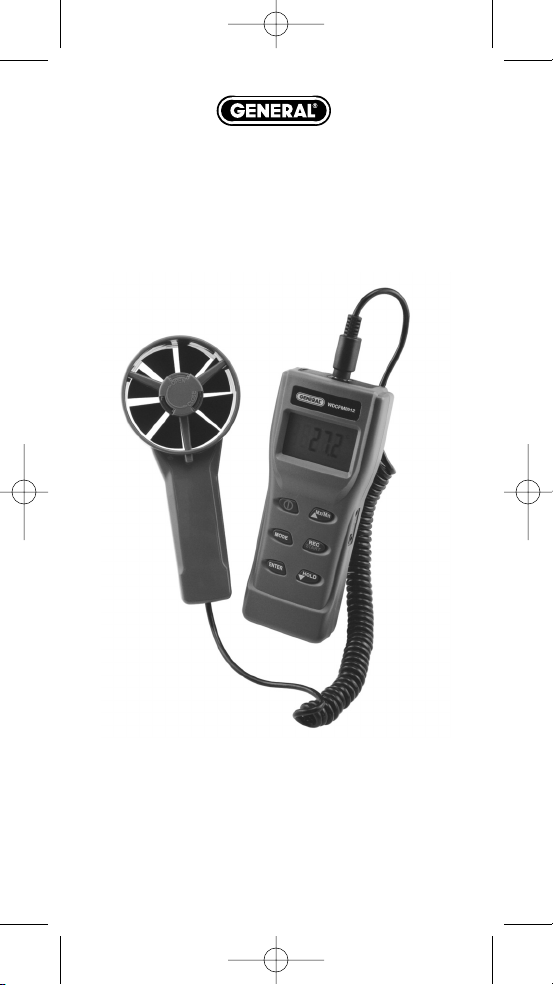
INTRODUCTION
Thank you for purchasing this digital Anemo-Psychrometer.
This unique meter is designed with 7 H.V.A.C &R that must have
parameters in 1. The meter is designed as battery operated for
Humidity,Air Temp., Dew Point, Wet Bulb, Air Velocity, Air Volume
and BTU.
The sensor is built in the remote fan and is specially protected by
tunable cap. While in operation, please turn on the cap to get
accurate temperature and humidity readings.
The psychrometer is a micro processor based design. A must
device for HVAC engineers use. No need to whirl the meter or refer
to charts. Easy to get wet bulb, dew point and BTU measurements
quickly!
FEATURES:
• Tunable cap to protect sensor
• Big LCD digit display
• Professional remote vane
• Metric & Imperial selectable
• Handheld size, easy to carry
• Low battery indication
• Fast response & Accurate reading
• Tripod mountable for long time use
• Dew Point calculated in seconds
• Wet Bulb calculated in seconds
• Microprocessor circuitry for reliability
• Sleep and non-sleep selectable
• Powered by 4 “AAA” batteries or 9VDC adaptor
• Back light for dark places
MATERIAL SUPPLIED
THIS PACKAGE CONTAINS:
• The meter
• Remote vane
• Battery 4 “AAA”
• Operation manual
• Hard carry case
OPTIONAL ACCESSORY:
• ASFT KIT includes RS232 cable & CD
2
WDCFM8912 Manual final2F-062708:Layout 1 6/27/08 10:55 AM Page 2
Page 3
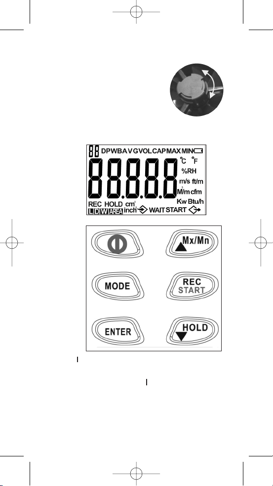
REMINDER
IMPORTANT:
1. Rotate the cover before measurement to
ensure the measured data is correct.
2. The fan and meter are sold as a kit and
are calibrated together.
When you need to replace the fan,
please see page 11 for details on
fan replacement.
CONTROLS AND INDICATORS LCD DISPLAY
LCD DISPLAY
KEY PAD
1. Power: O
- Turn on the meter with auto-sleep mode.
- Turn off the meter at any mode.
- When the meter is off, pressing
O more than two sec. to
enter units selection.
2. MODE:
- Pressing to select different modes.
Temp. DP WB RH Velocity.
- Pressing longer to select VOL and CAP.
3
WDCFM8912 Manual final2F-062708:Layout 1 6/27/08 10:55 AM Page 3
Page 4
3. ENTER:
- To confirm the setting & calibration.
4. Mx/Mn/Up
L
Mx/Mn
:
- Pressing to view MAX/MIN/AVG value.
- Press to select the value of each digit in cycle.
5. REC/START:
- To start measuring volume or capacity without waiting.
6. HOLD/Down
L
HOLD
:
- In basic modes pressing this key to hold the current reading,
then pressing this key again to unlock the holding.
- Pressing to select the setting digit.
7. Power +
L
Mx/Mn
:
- When the meter is off, pressing more than two sec. to enter
non-sleep mode.
8. Power +
L
Mx/Mn
+
M
HOLD
:
- Pressing more than two seconds to enter RH calibration mode.
9. ENTER +
L
HOLD
:
- Pressing to turn on/off the backlight.
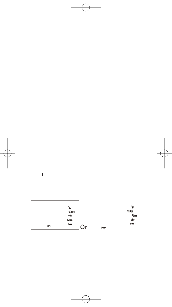
POWER ON/OFF & UNIT SELECTION
Press O to turn on the meter with auto-sleep mode. Press again
to turn off the meter at any mode.
When the meter is off, pressing
O more than two seconds to enter
units selection mode.
When in unit selection mode, press
L
Mx/Mn
or
M
HOLD
to select the
unit then, press
ENTER
to save and meter will be powered on
automatically.
4
WDCFM8912 Manual final2F-062708:Layout 1 6/27/08 10:55 AM Page 4
Page 5
BASIC MEASUREMENT
Basic measured parameters of this model:
BASIC MEASUREMENTS
• Air temp.
• Humidity
• Dew Point
• Wet Bulb
• Air Velocity
EXTENDED MEASUREMENTS
• Air Volume
• Sum of Volume
• Capacity
• Sum of Capacity
When powered on, the air temperature is the default value to show
on the LCD. To review the other basic parameters, just press the
MODE
key then each parameter will be displayed in turn.
While in basic mode, press
MODE
for over 2 seconds to enter extend
measurement mode. You can also press mode key to switch
between volume and capacity.
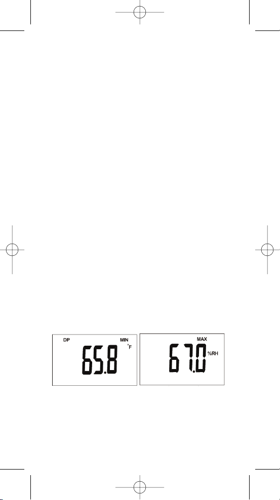
MAX, MIN & AVG.
When the meter is powered on, air temp., dew-point, WBT, humidity
& velocity is temporarily saved in meter, so, to press
L
Mx/Mn
could
view the average value minimum value and maximum value in
turns. Press
L
Mx/Mn
again to back to normal mode. The data will be
re-counted once the meter is powered off and turned on again.
When in Max/Min/Avg
MODE
, press the
MODE
key to display the
parameters you need. (Fig. A, Fig. B)
(Fig. A) (Fig. B)
5
WDCFM8912 Manual final2F-062708:Layout 1 6/27/08 10:55 AM Page 5
Page 6
AIR VOLUME: OUTLET SIZE
While in normal
MODE
, long pressing
MODE
key to enter air volume
mode.
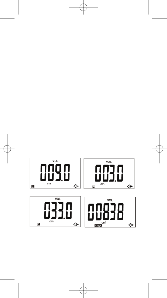
To measure the volume, the outlet size needs to be input first.
There are three choices to enter the size:
• Length & Width:
This is the default choice. Press
M
HOLD
key to select the setting
digit first, then press
L
Mx/Mn
key to select the appropriate value
(0-9). When selecting the value, the value will show from 0 to 9 in
cycle. After entering the length, short press
ENTER
to enter width
setting. Repeat the procedure of length setting, then short press
ENTER
again to finish the size setting and enter next step. (Fig. C)
• Diameter:
While in default outlet setting mode (length), press the
ENTER
key
for over two seconds to choose the diameter setting. Press
M
HOLD KEY
to select the setting digit first, then press
L
Mx/Mn
key
to select the appropriate value (0-9)
After selection, short press enter again to finish the size setting
and enter next step. (Fig. D)
• Area:
While in diameter setting mode, press the
ENTER
key for over two
seconds to enter the area setting.
Press
M
HOLD KEY
to select the setting digit first, then press
L
Mx/Mn
key to select the appropriate value (0-9)
• After selection, short press
ENTER
again to finish the size setting
and enter next step. (Fig. E)
(Fig. D) (Fig. E)
NOTE: Refer to page 9 for the range of each size input mode.
AIR VOLUME: MEASUREMENT
After short pressing
ENTER
to finish and leave size setting, there are
20 second waiting time for you to put the vane to the grill.
During the 20 second waiting time, the count down number
6
(Fig. C)
WDCFM8912 Manual final2F-062708:Layout 1 6/27/08 10:55 AM Page 6
Page 7
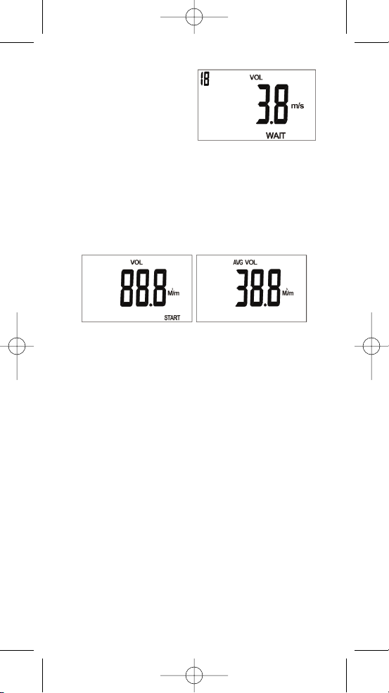
displayed on top left corner and
meter also beeps when time is
up. (Fig. F)
If no need to wait for 20
seconds, just press
REC/START
key to start measuring the
volume right away.
(Fig. F)
After starting measuring the volume, the meter will automatically
count the volume for 60 seconds to give a average value. (Fig. G)
During this 60 second time, the vane should move along the whole
outlet to cover each area so the measured data could be more
accurate. The count down number displayed on the top-Ieft corner
as a reminder and meter also beeps when 60 seconds is up.
After time is up, 60 seconds average volume will display on the
LCD as Fig H.
(Fig. G) (Fig. H)
If there are more than one outlet, you could press
ENTER
key again
to repeat the procedure from outlet size input. You could measure
outlet as many times as you need.
After measuring more than one outlet volume, you could press
L
Mx/Mn
key to review the sum of all outlets. Pressing or
M
HOLD
to
review the last outlet volume.
CAPACITY: OUTLET SIZE
While in normal mode, long pressing
MODE
to enter air volume, then
short press
MODE
to enter capacity mode. To measure the capacity,
put the vane on the Inlet, then press
ENTER
to count the 60 second
average Temp. & RH% ( Fig. I) countdown will show on left-top
corner of LCD and meter beeps after 60 second is up. Then, the
meter enters outlet size setting automatically. (Note 1)
There are three choice to enter the size:
• Length & Width:
This is the default choice. Press
M
HOLD
key to select the setting
digit first, then press
L
Mx/Mn
key to select the appropriate value
(0-9). When select the value, the value will show from 0 to 9 in
cycle. After entering length, short press
ENTER
to enter width
setting. Repeat the procedure of length setting, then short press
ENTER
again to finish the size setting and enter next step. (Flg. J)
7
WDCFM8912 Manual final2F-062708:Layout 1 6/27/08 10:55 AM Page 7
Page 8

• Diameter:
While in default outlet setting mode (length), pressing
ENTER
key
for over two seconds to choose diameter setting. Press
M
HOLD
key
to select the setting digit first, then press
L
Mx/Mn
key to select the
appropriate value (0-9)
(Fig. I) (Fig. J)
• Area:
While in diameter setting mode, pressing
ENTER
key for over two
seconds to enter area setting. Press
M
HOLD
key to select the
setting digit first, then press
L
Mx/Mn
key to select the appropriate
value (0-9)
After selection, short press
ENTER
again to finish the size setting
and enter next step. (Fig. L)
(Fig. K) (Fig. L)
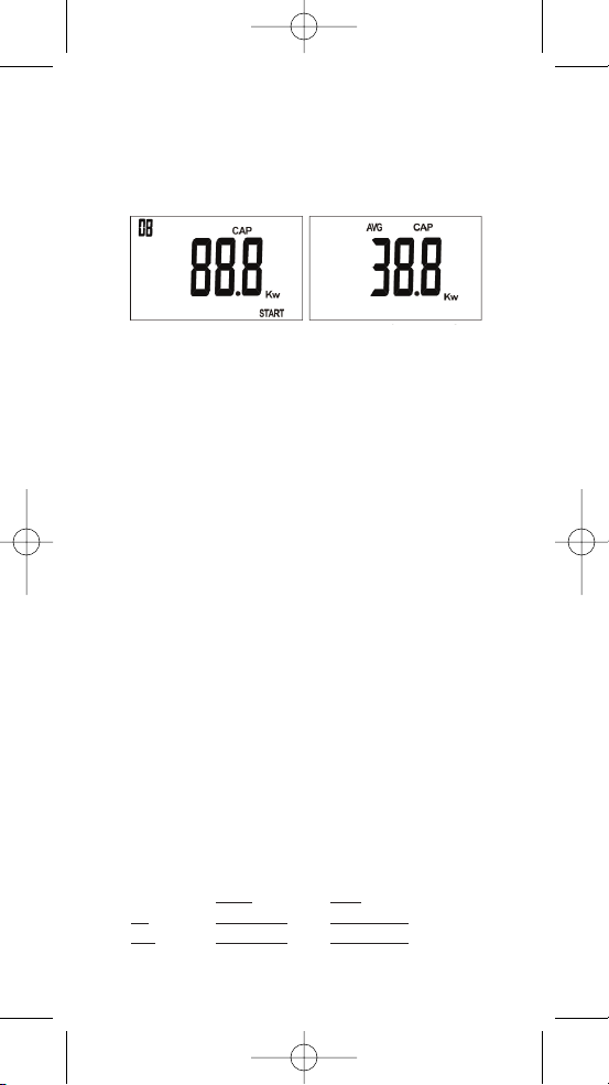
CAPACITY: MEASUREMENT
After short pressing
ENTER
to finish and leave size setting, there are
90 or 20 second (note 1) waiting time for you to put the vane to the
grill.
During above waiting time, the count down number displayed on
top-left corner and meter also beeps when time is up. (Fig. M)
If no need to wait for 90 or 20 seconds, just press
REC/START
key
to start measuring the capacity right away.
Note 1: If you have many outlets to
measure, while you start to measure
the second one, the waiting time
will adjust to 20 sec automatically.
90 sec. is the buffer for sensor to
stable. No matter in inlet or outlet,
suggest to move the vane along the
grill to get accurate values. (Fig. M)
After starting measuring the capacity, the meter will automatically
count the capacity for 60 seconds to give an average value. (Fig. N)
8
WDCFM8912 Manual final2F-062708:Layout 1 6/27/08 10:55 AM Page 8
Page 9
During this 60 second time, the vane should move along the whole
outlet to cover each area so the measured data could be more
accurate. The count down number displayed on the top-left corner
as a reminder and meter also beeps when 60 seconds is up.
After time is up, 60 seconds average volume will display on the
LCD as Fig O.
(Fig. N) (Fig. 0)
If there are more than one outlet, you could press
ENTER
key again
to repeat the procedure from outlet size input. You could measure
outlet as many as you need.
After measuring more than one outlet volume, you could press
L
Mx/Mn
key to review the sum of all outlets. Pressing
M
HOLD
key to
review the last outlet capacity.
If you would like to measure more than 1 inlet, please wait for 10
minutes and allow the humidity sensor to return to the room
humidity or help it by home ventilation.
LOW-BATTERY
Two level low battery indication:
• Level 1: Battery indicator will flash when at level 1. ln this
situation, the meter will work normal however users
should prepare new batteries.
• Level 2: Battery indicator will always display on the LCD while at
level 2. In this situation, users need to change batteries
immediately.
1. Open the battery cover on the rear side.
2. Remove the expired batteries.
3. Insert new “AAA” batteries and make sure the batteries are
inserted with correct polarity, replace the cover.
AC TO DC ADAPTOR
The compatible AC to DC adaptor is 9V and at least 200mA.
AVAILABLE SIZE RANGE
Please refer to below input size range. Please be reminded that in
metric L/W/D, the value after decal is not selectable.
L/W/D
AREA
cm 000.0-999.0 00000-99999
inch 000.0-999.9 00000-99999
9
WDCFM8912 Manual final2F-062708:Layout 1 6/27/08 10:55 AM Page 9
Page 10

RS232 SOFTWARE
SOFTWARE
We have compatible software and cable which is design for the
meter, please contact your supplier for details.
INTERFACE OF RS232
A. 9600 bps, 8 data bits, no parity.
B. Format: Tx. ASCII code by every sec. while meter is on
VXXX.XMPS(FTM):TXXX.XC(F):HXX.X%:
dXXX.XC(F):wXXX.XC(F):
vXXXXX.XCMM(CFM):
UXXXXX.XKW(BTU)
Where: The 1" value is velocity, the 2nd value is Air temp., the 3"
value is Humidity, the 4th value is Dew Point, the 5th value is Wet
bulb, the 6th value is AIR Volume, the 7th value is Capacity. The x
here means one of {0|1|2||9|-}
C. Format for error value:
E01 Probe is not connected; E02 Under flow;
E03 Over flow. See more in page The unit for error code is Nul.
EX:
V010.5MPS: TE02Nul: H66. 7%: dE04Nu:wE04Nul:v00020.5CMM.
TROUBLESHOOTING
1. Power on but no display
a) Make sure the time of pressing key is more than 0.1 second.
b) Check that the batteries are in place and in good contact with
correct polarity.
c) Replace a new battery and try again.
d) Remove the battery for one minute and put back again.
2. Display disappear
a) Check whether the low battery indicator was displayed before
Display faded, if yes, replace with new batteries.
b) Turn on the meter by pressing
O +
L
Mx/Mn
key to disable
auto power off function for longtime using.
3. E 1
a) The probe is disconnected or damaged.
4. E 2
a) The value is underflow.
5. E 3
a) The value is overflow.
4. E 4
a) The original data that is relative to this value error.
5. E 5
a) Out of meter display range.
10
WDCFM8912 Manual final2F-062708:Layout 1 6/27/08 10:55 AM Page 10
Page 11
6. E 6
a) the value is not calculated completely.
7. E 11
a) Humidity Calibration error.
SPECIFICATION
TEMPERATURE: -4º to 140ºF (-20º to 60ºC)
Accuracy: ±1ºF (±0.6ºC),
Resolution: 0.1ºF (0.1ºC)
RELATIVE HUMIDITY:
0 to 100% RH
Accuracy: ±3% at 10 to 90%RH (cal. temp.)
±5% at other range Resolution: 0.1 %
DEW POINT:
-90º to 158ºF (-68º to 70ºC)
Resolution: 0.1ºC
WET BULB TEMPERATURE:
-7.6º to 158ºF (-22º to 70ºC)
Resolution: 0.1ºC
AIR VELOCITY:
1 to 114 ft/s (0.3 to 35 m/s)
Accuracy: ±5%
Resolution: 0.1
AIR VOLUME:
0 to 99999 cfm (0 to 99999 m3/s) Accuracy: ±5%
Resolution 0.1 (0 - 9999.9) or 1 (10000 - 99999)
ADDITIONAL FEATURES:
BTU CAPACITY: 0 to 99999 BTU/H (KW)
Resolution. 0.1 (0 -9999.9) or 1 (10000 99999)
Dimension:
(HxWxD)
Vane. 6.7" x 3" x 1.6" (170 x 77 x 40mm)
Meter. 6.9" x 2.8" x 1.3" (175 x 70 x 33mm)
Power: 4 “AAA” batteries or 9V >200mA adaptor.
FAN REPLACEMENT
If users have more than one set anemometers or users change a
new fan for his old meter, user should input the RH% calibration
data which enclosed with each fan. The data will be recorded in a
slip of paper and ship with fan, please keep the paper well for
future use.
There are two calibration data need to be inputted. First value is
“Slope, S” and the second value is “Intercept, Z”
SLOPE (VALUE S)
1. While the meter is off, press O +
L
Mx/Mn
+
REC/START
at the
same time for 2 seconds to enter humidity slope calibration
mode. LCD will display current saved S value and the last digit
will flash to indicate the value is ready for edit.
11
WDCFM8912 Manual final2F-062708:Layout 1 6/27/08 10:55 AM Page 11
Page 12

2. If the saved S value is different from your paper, press
M
HOLD
key
to move to the digit which you want to edit and then use
L
Mx/Mn
key to change the value.
3. Press
ENTER
key to save new input S value and then meter will
enter second value input automatically.
IMPORTANT NOTE: While setting the slope, only input 5 digits after
decimal point, so user need to round off the 6th digit.
User should also input two digits before decimal.
Example:
1. If the S value is 8.239678, user should input 08 23968
2. If the S value is 11.23968, user should input 11 23968
3. If the S value is 0.2396838, user should input 00 23968 (Fig. S)
(Fig. S)
INTERCEPT (VALUE Z)
1. While press
ENTER
key save the S setting, the meter will enter
intercept input automatically. The last digit will flash to indicate
the Z value is now ready for edit.
2. If the last saved Z value is different from your paper, press
M
HOLD
key to move to the digit which you want to edit and then use
L
Mx/Mn
key to change the value.
3. Press
ENTER
key to save new input Z value and then meter will be
back to normal RH value mode.
IMPORTANT NOTE: While setting Z value, only input 3 digits after
decimal point, so user need to round off the 4th digit.
12
WDCFM8912 Manual final2F-062708:Layout 1 6/27/08 10:55 AM Page 12
Page 13

User should also input four digits before decimal. All the Z is a
negative value but LCD will not appear the negative icon. Example:
1. If the Z value is -928.8683, user should input 09
28868
2. If the Z value is -1928.868, user should input 19 28868
3. If the Z value is -89.68482, user should input 00 89685 (Fig. T)
(Fig. T)
RETURN AUTHORIZATION
Authorization must be obtained from the supplier before returning
items for any reason. When requiring a RA (Return Authorization),
please include data regarding the defective reason, the meters are
returned along with good packing to prevent any damage in
shipment and insured against possible damage or loss.
13
WDCFM8912 Manual final2F-062708:Layout 1 6/27/08 10:55 AM Page 13
Page 14

NOTES
______________________________________________________
______________________________________________________
______________________________________________________
______________________________________________________
______________________________________________________
______________________________________________________
______________________________________________________
______________________________________________________
______________________________________________________
______________________________________________________
______________________________________________________
______________________________________________________
______________________________________________________
______________________________________________________
______________________________________________________
______________________________________________________
______________________________________________________
______________________________________________________
______________________________________________________
______________________________________________________
______________________________________________________
______________________________________________________
______________________________________________________
WDCFM8912 Manual final2F-062708:Layout 1 6/27/08 10:55 AM Page 14
Page 15

______________________________________________________
______________________________________________________
______________________________________________________
______________________________________________________
______________________________________________________
______________________________________________________
______________________________________________________
______________________________________________________
______________________________________________________
______________________________________________________
______________________________________________________
______________________________________________________
______________________________________________________
______________________________________________________
______________________________________________________
______________________________________________________
______________________________________________________
______________________________________________________
______________________________________________________
______________________________________________________
______________________________________________________
______________________________________________________
______________________________________________________
______________________________________________________
WDCFM8912 Manual final2F-062708:Layout 1 6/27/08 10:55 AM Page 15
Page 16
General TOOLS & INSTRUMENTS
™
80 White Street, New York,NY10013
-
3567
PHONE (212) 431-6100
FAX (212) 431-6499
TOLL FREE (800) 697-8665
e-mail: sales@generaltools.com
www.generaltools.com
WDCFM8912 User’s Manual
Specifications subject to change without notice
©2008 GENERAL TOOLS & INSTRUMENTS
™
NOTICE - WE ARE NOT RESPONSIBLE FOR TYPOGRAPHICAL ERRORS.
MAN#WDCFM8912 7/08
WDCFM8912 Manual final2F-062708:Layout 1 6/27/08 10:55 AM Page 16
 Loading...