

Page 1
NON-CONTACT
VOLTAGE DETECTOR
WITH ADJUSTABLE
SENSITIVITY AND
IR THERMOMETER
USER’S MANUAL
VR40
Please read this manual carefully and thoroughly
before using this product.
Page 2

TABLE OF CONTENTS
Introduction . . . . . . . . . . . . . . . . . . . . . . . . . 3 –6
Key Features . . . . . . . . . . . . . . . . . . . . . . . . . . . 6
Safety Instructions . . . . . . . . . . . . . . . . . . . . 7 –9
What’s in the Blister Pack . . . . . . . . . . . . . . . . 10
Product Overview . . . . . . . . . . . . . . . . . . . 10 – 12
Setup Instructions . . . . . . . . . . . . . . . . . . . . . . 13
Install Batteries. . . . . . . . . . . . . . . . . . . . . . . 13
Operating Instructions . . . . . . . . . . . . . . . 13 – 19
Detecting AC Voltage . . . . . . . . . . . . . . 13 – 16
Using the IRT to Measure Temperature
Specifications. . . . . . . . . . . . . . . . . . . . . . 19 – 20
Operating & Maintenance Tips . . . . . . . . . 20 – 21
Warranty Information . . . . . . . . . . . . . . . . . . . . 22
Return for Repair Policy . . . . . . . . . . . . . . . . . . 23
. 16 – 19
2
Page 3

INTRODUCTION
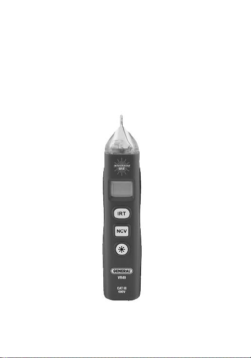
Thank you for purchasing General Tools & Instruments’
(General’s) VR40 Non-contact Voltage Detector with
Adjustable Sensitivity and IR Thermometer. Please read
this manual carefully and thoroughly before using the
instrument.
The VR40 offers a safe (non-contact) way to check
whether a line, cable or AC outlet is “hot” (energized).
It does so by using a blade tip to sense from a short
distance the electromagnetic field created by AC
voltage. When voltage is detected, the VR40 produces
audible and visual alarms (a beeping sound, and a
flashing red light adjacent to the tip.
Even unloaded AC circuits generate electromagnetic
fields. Although these fields are extremely weak, their
constantly changing nature means that they generate
some current. A sensitive non-contact voltage (NCV)
detector can sense this current via induction, in much
the same way that a sensitive radio receiver can sense
weak radio waves.
NCV detectors, including the VR40, cannot detect DC
voltages, such as those present in automotive electrical
systems. In addition, the VR40 typically cannot detect
120VAC from a distance of more than 0.25 in. (6.2mm),
and never through a wall or metal conduit.
3
Page 4

Unlike other NCV detectors with only one sensitivity
level—and therefore the ability to detect only one range
of voltages (typically 50 to 600VAC)—General’s VR40 has
four sensitivity levels. They were chosen to optimize
voltage detection over four practical ranges: 12 to 25VAC,
70 to 125VAC, 150 to 240VAC and 250 to 600VAC.
The ability to detect the presence of 12VAC in noncontact fashion comes in very handy during
troubleshooting of branch circuits and process plant
and industrial automation systems and equipment such
as gas and water valves, fans, lights, relays, inverters,
solenoids and horns. 12VAC is also commonly used to
power hardwired commercial and residential building
doorbells/buzzers and thermostats. Separately, the
VR40’s ability to detect 480V using its lowest sensitivity
range makes troubleshooting and installing generators
and fluorescent lighting ballasts easier, faster and safer.
User-adjustable sensitivity does more than make the
VR40 more versatile. It also improves the instrument’s
performance. The value of the VR40’s highest sensitivity
level (12 to 25VAC) is obvious: it allows non-contact
detection of 12VAC, an ability that most other NCV
detectors lack. However, the VR40’s lower sensitivity
levels, which cover common AC power voltages, also
have great value, for the following reason.
4
Page 5

Merely detecting the presence of 120VAC near a bundle
of wires does not tell you which wire of the bundle is
the “hot” wire; any of the wires could be activating the
alarms. The VR40 can help you isolate the hot wire. This
application calls for turning down the sensitivity in
stages after the NCV detector senses voltage. As you
reduce sensitivity, at some stage only the energized
wire will produce a field strong enough to activate the
NCV’s alarms. In this way, the VR40’s adjustable
sensitivity takes the guesswork out of identifying the
“hot” wire of a bundle.
Four additional features increase the versatility and
utility of the VR40:
• Because its tip can fit in the slots of 110VAC
receptacles, as it checks for voltage the VR40 also
indicates whether the receptacle is wired correctly, or
wired in reverse.
• A bright white LED flashlight
• An infrared thermometer (IRT) for non-contact
measurement of local surface temperatures. Using an
IRT is a safe, reliable way to detect and isolate
overload currents in motors and electrical conduit and
junction boxes. Measured temperatures are displayed
in °F or °C on a 4-digit (2000 count) LCD and
automatically held for 15 seconds after the IRT
activation button is released.
5
Page 6

• A unique, patent-pending ergonomic design that
places the IR and NCV sensors and the flashlight on
the same end of the instrument.
KEY FEATURES
• Dual indications (beeper sounds and red LED under
translucent cap flashes) when voltage is detected
• Unique adjustable sensitivity feature enables accurate
detection of voltage on 12VAC to 480VAC branch
circuits and makes individual live wires in bundles
easier to isolate
• Safe for CAT III 600V use
• Also checks 110VAC outlets for reversed wiring and
open circuits
• 4:1 IRT with measurement range of -4° to 626°F
(-20° to 330°C) and fixed emissivity
• 4-digit (2000 count) LCD temperature readout in
°F or °C
• Powerful white LED flashlight under translucent cap
• 15-second Auto Power Off (APO)
• Low battery indication
• Pocket clip on back
• Powered by (2) “AAA” batteries
6
Page 7

SAFETY INSTRUCTIONS
• WARNING •
• You must confirm that the batteries powering the
VR40 are not weak or dead before you use the unit to
test for the presence of AC voltage. It is essential that
you do this each time you use the instrument.
The usual way to check the batteries is to insert the
blade tip into both slots of an outlet known to be
energized; if the beeper does not sound and the LED
does not light for either slot, replace both “AAA”
batteries before proceeding. Another simple way to
check for live batteries is to briskly rub the tip of the
unit through your hair; static electricity has more than
enough voltage to activate the beeper and LED.
• The VR40 is designed to indicate the presence of AC
voltage with an amplitude between 12VAC and
600VAC. Accordingly, do not assume that the absence
of a positive indication means that the circuit under
test is de-energized (not “hot”). Although they can
cause shock and/or serious personal injury, voltages
below 12V may not be detected by the VR40.
Whenever you have reason to suspect that a line or
outlet is “hot”, confirm your suspicion by measuring
the voltage of the line or outlet with a multimeter or
clamp meter.
7
Page 8

• Physically separate the multiple lines of 2-phase and
3-phase circuits before testing them.
• Do not use the VR40 if it appears to be damaged or
malfunctioning.
• Do not expose the tester to temperatures above
113°F (45°C), relative humidity greater than 95%, or
voltages higher than 600V.
• Do not use the VR40 to test for the presence of DC
voltage.
• Do not use the unit to test for the presence of AC
voltage on a shielded conductor, behind a wall or
conduit, or under soil.
• Keep your fingers well behind the tip when
performing a test. Never touch any conductor with
your hand or skin until you have confirmed that it is
not “hot”. To repeat: whenever you have reason to
believe that a line or outlet is “hot”, measure its
voltage with a multimeter or clamp meter.
8
Page 9

The VR40 is a Class 2 laser product that emits less
than 1mW of radiation at a wavelength between 630
and 650nm. Avoid looking directly at the laser pointer.
U.S. law prohibits pointing a laser beam at aircraft;
doing so is punishable by a fine of up to $10,000 and
imprisonment.
• The laser may cause discomfort if viewed directly.
Your eyes’ natural aversion reflex will prevent you
from looking at the beam long enough to cause harm.
As a precaution, keep the VR40 out of the hands of
children, especially if you have pets.
• Never stare at the laser beam through binoculars or a
magnifying glass.
• Do not operate the VR40 in the presence of
flammable or explosive gases or in environments full
of dust or static electricity.
• Do not operate the unit near a source of a strong
electromagnetic field, such as an arc welder or an
induction heater.
9
Page 10
WHAT’S IN THE BLISTER PACK
The VR40 comes fully assembled in a blister pack along
with (2) “AAA” batteries and this user’s manual.
PRODUCT OVERVIEW
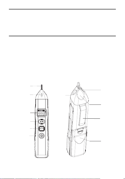
Fig. 1 shows the controls, indicators and key
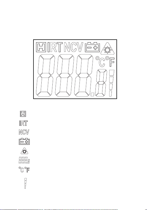
components of the VR40. Figure 2 shows all possible
indicators on the unit’s LCD. Familiarize yourself with
the labels, positions and functions of all buttons and
components before moving on to the Setup Instructions
and Operating Instructions.
q
w
u
i
o
e
r
s
t
y
a
Fig. 1. The controls, indicators and key components
of the VR40.
10
Page 11

1 Non-contact voltage (NCV) detection blade tip
2 NCV detection LED (glows red)
3 LCD
4 Two-function IRT button: 1) Pressed by itself (briefly
or held), activates IR thermometer and laser pointer,
producing a temperature readout. When button is
released, readout is held for 20 seconds, until APO
function activates. 2) With NCV button pressed and
held, each press of IRT button reduces sensitivity of
NCV detector by one level. With sensitivity at lowest
level, next press of button returns detector to
maximum sensitivity. The last sensitivity level
selected is recalled the next time the VR40 is
activated.
5 Two-function NCV button. 1) Pressed and held by
itself, activates NCV detection circuit. 2) With IRT
button pressed and held, each press of NCV button
toggles unit of temperature readout between °C and
°F. The last temperature unit selected is recalled the
next time the VR40 is activated.
6 LED flashlight button. Activates flashlight only when
VR40 is active (display is not blank)
7 Laser pointer window
8 LED flashlight window
11
Page 12
9 Infrared sensor
10 Battery compartment
11 Pocket clip
Fig. 2. All possible display indications.
12
Data hold on
IR temperature readout on
Non-contact voltage detection on
Low battery indication
Laser pointer on
IR temperature value
IR temperature units
NCV sensitivity level bar graph; default level at
power on is last level used before APO timeout
Page 13

SETUP INSTRUCTIONS
INSTALL BATTERIES
The VR40’s battery compartment (Fig. 1, Callout 10) is
accessible from the back of the unit.
To open the compartment, place your thumbnail in the
slot above the word OPEN and apply enough force to
release the battery compartment cover. Slide the cover
down and away from the instrument.
Insert the two supplied “AAA” batteries in the well
using the and markings stenciled inside the
compartment as an orientation guide. Slide the battery
compartment cover back onto its rails and push it
forward until it snaps shut.
OPERATING INSTRUCTIONS
DETECTING AC VOLTAGE
Before using the VR40 to detect the presence of AC
voltage, you must check a known "hot" outlet to
confirm that the batteries powering the instrument are
not weak or dead. It is essential that you do this each
time you use the unit for this purpose.
To check the charge of the batteries, press and hold
the NCV button while inserting the blade tip into both
slots of an 110VAC outlet known to be energized. If the
13
Page 14

batteries are charged, the beeper will sound repeatedly
and the red LED under the translucent cap (Fig. 1,
Callout 2) will flash when the tip is in one of the slots.
Alternatively, briskly rub the tip of the VR40 through your
hair or against your skin; static electricity has more than
enough voltage to activate the beeper and LED.
Whenever the NCV detection circuit is active, the
icon will appear on the top line of the LCD.
Before checking whether an unknown 110VAC
outlet is energized, it is important that you first
maximize the VR40’s sensitivity. To do so, while
pressing and holding the NCV button press the IRT
button as many times as necessary until “four bars”
show on the NCV sensitivity level bar graph at the lower
right of the LCD.
To check whether an unknown 110VAC outlet is
energized, press and hold the NCV button while
inserting the blade tip of the VR40 into both slots of the
outlet, one at a time.
1. If the beeper sounds and the NCV detection LED near
the tip (Fig. 1, Callout 2) flashes when the tip is
inserted in the smaller slot of a modern 15A outlet
(right slot of left figure on next page), the outlet is
both energized and properly wired (the smaller
slot is “hot” and the larger slot is neutral).
14
Page 15

The figure below also shows which slots of two other
common 110VAC receptacles are hot. In both cases,
the “hot” slot is on the right and smaller.
2. If the beeper sounds and the LED flashes when the
tip is in the larger (left) slot of a modern 15A outlet,
the outlet is energized but wired in reverse.
3. If the beeper does not sound and the LED does not
light when the tip is in either slot, the circuit is
de-energized.
Modern NEMA 5-15
outlet
Modern NEMA 5-20
outlet
Old NEMA 1-15
outlet
To determine whether an unknown 220VAC outlet is
energized, first maximize the VR40’s sensitivity by
pressing and holding the NCV button and
simultaneously pressing the IRT button as many times
as necessary until “four bars” show on the NCV
sensitivity level bar graph. Then press and hold the NCV
button while inserting the blade tip of the VR40 into all
slots of the outlet, one at a time. If the beeper sounds
and the NCV detection LED near the tip flashes with the
tip inserted in any slot, the outlet is energized.
15
Page 16

To detect the presence of AC voltage on an
individual line or cable, position the blade tip within
1/4 inch of the line or cable and press and hold the
NCV button. If the beeper sounds and the LED lights,
the line or cable is “hot” (energized). If you do not get
both positive indications, touch the tip to all four sides
of the line or cable. If the beeper sounds and the LED
lights, the line or cable is “hot” (energized). If you still
do not get positive indications, the line or cable is deenergized.
To determine whether a device powered by 480VAC
(a generator or ballast, for example) is energized,
simply position the tip of the VR40 near it. If the beeper
sounds and the LED lights, the device is “hot”
(energized). If you do not get both positive indications,
the device is de-energized.
USING THE IRT TO MEASURE TEMPERATURE
To use the VR40’s integrated IR thermometer to
measure the temperature of a surface, point the front
of the unit at a surface and press and hold the IRT
button. Note that this activates the laser pointer of the
VR40’s integrated IR thermometer and causes the
icon to appear at the top right of the LCD. Use the laser
pointer to “zero in” on the target—the object or surface
whose temperature you wish to measure. The
16
Page 17

measured temperature will be displayed on the LCD,
along with the icon on the top line.
When you make temperature measurements, be sure
to get close enough to the target to ensure that you are
reading its temperature alone, rather than the average
temperature of the target and objects behind or near it
within the IRT’s field of view.
The IRT in the VR40 has a distance-to-spot (D:S) ratio
of 4:1. This means that the target area (spot) whose
infrared radiation (temperature) is being measured
increases in diameter by 1 inch for every 4 inches you
move away from the target. Conversely, the diameter of
the target area measured decreases by 1 inch for every
4 inches you move closer to the target.
All IRTs, including the one in the VR40, take the average
temperature of all objects within a circular target area
(spot). Although the distance “D” in the D:S ratio is
defined as a linear value and the “S” defines the
diameter of the spot (see figure at top of next page), the
critical parameter is the target area. Depending on the
distance to the target, the target area may include both
the target and background objects near or behind the
thermometer’s field of view, which defines the target
area or spot.
17
Page 18

D:S=4:1
To eliminate measurement error, the VR40 must be
moved close enough to the target so it is the only object
in the target area. The figure below illustrates
measurement of a motor’s temperature from the wrong
(top) and right (bottom) distance. For a motor with an
area of 1 ft
2
, the optimum measurement distance for
the 4:1 IRT in the VR40 would be 4 ft.
Note that when you release the IRT button after
measuring a surface temperature, the reading will be
held on the LCD for 20 seconds, until the Auto Power
Off (APO) function activates and powers off the
instrument. During this period of time, the and
icons will appear at the upper left of the LCD. During
this interval, you can change the temperature unit of
the readout.
18
Page 19

To change the temperature unit, press the NCV and
IRT buttons at the same time. Each simultaneous press
will toggle the unit between °C and °F. The selected unit
will appear on the display to the right of the measured
IR temperature value. The last temperature unit
selected will be recalled the next time the VR40 is
activated.
To temperature-scan the surfaces of a room or any
environment, press and hold the IRT button as you aim
the laser pointer in various directions. Note that the IR
temperature readout will track the different
temperatures of different surfaces in real time, and hold
the temperature of the surface being scanned when
you release the IRT button.
SPECIFICATIONS
Overall Voltage Detection Range: 12 to 600VAC
@ 50/60Hz
Detection Ranges/Sensitivities: 12 to 25VAC,
70 to 125VAC, 150 to 240VAC, 250 to 600VAC
Non-contact Detection Distance: 0.25 in. (6.2mm), max
Safety Rating: CAT III 600V
IR Thermometer D:S Ratio: 4:1
IRT Measurement Range: -4° to 626°F (-20° to 330°C)
19
Page 20

Measurement Accuracy: ±3°F (2°C) or ±1% of reading
(whichever is greater) above 32°F; ±4.5°F (2.5°C)
below 32°F
IRT Emissivity: Fixed at 0.95
IR Sensor Spectral Range: 8 to 14
μm
Display Size and Type: 5/8 in. (16mm) diagonal LCD
Display Digits/Counts/Resolution: 4/ 2000/0.1° (F or C)
Laser Pointer Class/Power/Wavelength:
Class 2/<1mW/630 to 650nm
Sampling Time: 2X/second
Auto Power Off Trigger: 15 seconds of inactivity
Operating Temperature: 32° to 113°F (0° to 45°C)
@ <95% RH
Storage Temperature: 14° to 122°F (-10° to 50°C)
@ <95%RH
Dimensions: 6.0 x 1.2 x 1.2 in. (152 x 31 x 31mm)
Weight (with batteries): 7.8 oz. (220g)
Power Source: 2 “AAA” (LR03) batteries (included)
OPERATING &
MAINTENANCE TIPS
• When the icon appears on the top line of the
LCD, replace the batteries by following the procedure
on p. 13. Use Alkaline batteries only.
20
Page 21

• If the temperature of the IRT’s target is lower than
-4°F (-20°C)—the lower limit of the unit’s
measurement range—“LO” will appear on the
readout.
• If the temperature of the IRT’s target is higher than
626°F (330°C)—the upper limit of the unit’s
measurement range—“HI” will appear on the
readout.
• The IRT cannot make accurate measurements if there
is glass or plastic between it and the target.
• Clean the lens of the infrared sensor (Fig. 1, Callout 9)
often—but never use a solvent.
• Abrupt temperature changes will cause condensation
and possible vapor penetration. Clean the LCD after
the vapor evaporates. Blow off loose particles with
clean, compressed air. Gently brush remaining debris
away with a lens hair brush.
• To clean the housing, use a moist cotton swab or wet
sponge. Avoid excessive amounts of water and
corrosive gas or liquids.
• Remove the batteries if you don’t expect to use the
VR40 for an extended period of time (months or
years).
• Do not drop or disassemble the instrument or
immerse it in water.
21
Page 22

WARRANTY INFORMATION
General Tools & Instruments’ (General’s) VR40
Non-contact Voltage Detector with Adjustable Sensitivity
and IR Thermometer is warranted to the original
purchaser to be free from defects in material and
workmanship for a period of three years. Subject to
certain restrictions, General will repair or replace this
instrument if, after examination, the company determines
it to be defective in material or workmanship.
This warranty does not apply to damages that General
determines to be from an attempted repair by nonauthorized personnel or misuse, alterations, normal
wear and tear, or accidental damage. The defective unit
must be returned to General Tools & Instruments or to a
General-authorized service center, freight prepaid and
insured.
Acceptance of the exclusive repair and replacement
remedies described herein is a condition of the contract
for purchase of this product. In no event shall General
be liable for any incidental, special, consequential or
punitive damages, or for any cost, attorneys’ fees,
expenses, or losses alleged to be a consequence of any
damage due to failure of, or defect in any product
including, but not limited to, any claims for loss of
profits.
22
Page 23

RETURN FOR REPAIR POLICY
Every effort has been made to provide you with a
reliable product of superior quality. However, in the
event your instrument requires repair, please contact
our Customer Service to obtain an RGA (Return Goods
Authorization) number before forwarding the unit via
prepaid freight to the attention of our Service Center at
this address:
General Tools & Instruments
80 White Street
New York, NY 10013
212-431-6100
Remember to include a copy of your proof of purchase,
your return address, and your phone number and/or
e-mail address.
23
Page 24

GENERAL TOOLS & INSTRUMENTS
80 White Street
New York, NY 10013-3567
PHONE (212) 431-6100
FAX (212) 431-6499
TOLL FREE (800) 697-8665
e-mail: sales@generaltools.com
www.generaltools.com
VR40 User’s Manual
Specifications subject to change without notice
©2013 GENERAL TOOLS & INSTRUMENTS
NOTICE - WE ARE NOT RESPONSIBLE FOR
TYPOGRAPHICAL ERRORS.
MAN# VR40
7/29/13
 Loading...