

Page 1

14-IN-1 DATA LOGGING
THERMO-HYGROMETER
WITH PIN/PINLESS MOISTURE METER
USER’S MANUAL
RHMG700DL
Please read this manual carefully and thoroughly before using this product.
Page 2

TABLE OF CONTENTS
Introduction . . . . . . . . . . . . . . . . . . . . . . . . . . . . . . . . . . . . . . . . . . . . . . . . . . . . 2 –4
Key Features . . . . . . . . . . . . . . . . . . . . . . . . . . . . . . . . . . . . . . . . . . . . . . . . . . . . . . 4
Safety Instructions . . . . . . . . . . . . . . . . . . . . . . . . . . . . . . . . . . . . . . . . . . . . . . . . . . 4
What’s in the Package . . . . . . . . . . . . . . . . . . . . . . . . . . . . . . . . . . . . . . . . . . . . . . . 4
Product Overview . . . . . . . . . . . . . . . . . . . . . . . . . . . . . . . . . . . . . . . . . . . . . . . 5 –7
Setup Instructions . . . . . . . . . . . . . . . . . . . . . . . . . . . . . . . . . . . . . . . . . . . . . . . . . . 7
Install Battery . . . . . . . . . . . . . . . . . . . . . . . . . . . . . . . . . . . . . . . . . . . . . . . . . . 7
Operating Instructions . . . . . . . . . . . . . . . . . . . . . . . . . . . . . . . . . . . . . . . . . . . 7 – 15
Powering On and Off . . . . . . . . . . . . . . . . . . . . . . . . . . . . . . . . . . . . . . . . . . . . . 8
Selecting a Parameter . . . . . . . . . . . . . . . . . . . . . . . . . . . . . . . . . . . . . . . . . . . 8
General Controls . . . . . . . . . . . . . . . . . . . . . . . . . . . . . . . . . . . . . . . . . . . . . 8 –9
Recalling Stored Readings . . . . . . . . . . . . . . . . . . . . . . . . . . . . . . . . . . . . . . . . 9
Setting Alarms . . . . . . . . . . . . . . . . . . . . . . . . . . . . . . . . . . . . . . . . . . . . . 9 – 11
Measuring Moisture Levels . . . . . . . . . . . . . . . . . . . . . . . . . . . . . . . . . . . 11 – 12
Checking Calibration . . . . . . . . . . . . . . . . . . . . . . . . . . . . . . . . . . . . . . . . . . . .12
Data Logging . . . . . . . . . . . . . . . . . . . . . . . . . . . . . . . . . . . . . . . . . . . . . . 12 – 15
Viewing Data Logging Settings . . . . . . . . . . . . . . . . . . . . . . . . . 12 – 13
Changing Data Logging Settings . . . . . . . . . . . . . . . . . . . . . . . . 13 – 14
Clearing Data Logs . . . . . . . . . . . . . . . . . . . . . . . . . . . . . . . . . . . 14 – 15
Starting and Stopping Data Logging . . . . . . . . . . . . . . . . . . . . . . . . . 15
Using the Included Software . . . . . . . . . . . . . . . . . . . . . . . . . . . . . . . . . . 15 – 16
Specifications . . . . . . . . . . . . . . . . . . . . . . . . . . . . . . . . . . . . . . . . . . . . . . . . . . . . 17
Operating & Maintenance Tips . . . . . . . . . . . . . . . . . . . . . . . . . . . . . . . . . . . . . . . . 18
Warranty Information . . . . . . . . . . . . . . . . . . . . . . . . . . . . . . . . . . . . . . . . . . . . . . . 18
Return for Repair Policy . . . . . . . . . . . . . . . . . . . . . . . . . . . . . . . . . . . . . . . . . . . . . 19
INTRODUCTION
Thank you for purchasing General Tools & Instruments’ (General’s) RHMG700DL 14-in-1 Data
Logging Thermo-Hygrometer with Pin/Pinless Moisture Meter. Please read this user’s manual
carefully and thoroughly before using the instrument.
The RHMG700DL is a handheld instrument that will prove useful to three broad groups of users:
HVAC/R system installers and technicians, facility maintenance professionals and water damage
restoration contractors.
The first two groups will exploit the meter’s ability to measure, display and store/recall ten
condensation-related parameters: ambient temperature, relative humidity (RH), absolute humidity
(AH), GPP (mixing ratio—in grains per pound or g/kg), dew point, wet bulb temperature, surface
temperature (using an optional “K” type thermocouple probe), condensation temperature (using
an optional “K” type thermocouple probe), atmospheric pressure and vapor pressure. The meter’s
2
Page 3

large, primary readouts of each of the last eight parameters are accompanied by a smaller,
secondary readout of the first parameter: ambient temperature. The ten parameters measured,
monitored and displayed—individually or in pairs—by the RHMG700DL are most valuable in two
applications:
• Environmental monitoring of office buildings, greenhouses, food and equipment storage
facilities, wineries, freezers, shipping containers, HVAC/R installations, computer rooms, labs,
libraries, museums and saunas.
• Electronics manufacturing. Alerts provided by the low RH alarm of the RHMG700DL can
mitigate the risk of damaging high-voltage static discharges.
Water damage remediators will also make use of the RHMG700DL’s ability to calculate an
environment’s mixing ratio (often represented using the unit GPP, or grains per pound). GPP is a
more useful moisture metric than RH to water damage remediators. Using RH alone, a remediator
might unknowingly introduce moist air—with a low RH but a high GPP—during a job’s drying
phase.
Another parameter of interest to water damage remediators is the moisture level of a substance
(typically, wood or building materials). The RHMG700DL can measure this parameter using either
a pinless (non-marring) or pin-type (penetrating) probe; the meter includes both kinds of probe.
Operating in internal moisture mode, the meter uses a non-invasive (pinless) sensor on the back
of the unit to detect moisture up to 3/4 in. (20mm) below the surface of the following materials:
wallboard, masonry, hardwood and softwood. It infers the level of moisture from the material’s
capacitance, which the meter measures by gauging its effect on an electric field that the meter
generates each time it is operated in internal moisture mode.
In internal moisture mode, the meter exploits two physical phenomena to make its
measurements:
1. The linear relationship between a solid material’s moisture level and its dielectric constant—
and therefore its capacitance.
2. The so-called fringing-field effect—the slight spreading of the electric field produced by current
flowing between two electrodes when both electrodes are on the same side of a material.
Behind the back cover of the RHMG700DL are two metal plates. When the meter is powered on,
the plates are given small and opposite charges. The potential difference causes current to flow,
creating a three-dimensional electric field.
When the back of the meter is placed against one side of a material with moisture on or slightly
below its surface, the increased capacitance of the material distorts the electric field to an extent
that can be sensed (as a change in flux over the sensing area) and measured. Displayed readings
reflect the average moisture level of the material between its surface and the electric field’s
maximum penetration of 3/4 in. Moisture closer to the surface has a greater effect on readings
than moisture at the maximum penetration depth.
In external moisture mode, the meter bases its measurements on the relationship between the
moisture content of a material and its electrical conductivity. The wetter a material, the higher its
conductivity. The two replaceable steel pins of the included external probe serve as the
electrodes of a conductance meter optimized for measuring moisture content. The meter displays
measurements in the unit %WME (Wood Moisture Equivalent).
3
Page 4

For hard materials like wood or concrete, the meter’s readings largely reflect surface moisture
content because: 1) Moisture close to a surface has a greater effect on a reading than moisture
deep below it; and 2) The pins of the external probe are only 3/8 in. (10mm) long and cannot be
driven deep into a hard material. For softer materials like soil, paper or powders, readings are
more likely to reflect the average moisture level of the material between its surface and the
penetration depth of the pins (normally far less than 3/8 in.).
The instrument can be set up to sound an alarm if a measured RH or moisture level is above or
below a user-defined setpoint. Finally, the unit can track the maximum or minimum reading of
any parameter over the duration of a measurement session.
The RHMG700DL can store and recall 20 pairs of measurements in internal nonvolatile memory.
It can also log (with date and time stamps) up to 8000 data points internally, for later download to
a PC and display as an Excel-formatted graph or table.
KEY FEATURES
• Measures 1) ambient temperature, 2) relative humidity (RH), 3) absolute humidity (AH, in
mg/L or g/m
3
), 4) GPP (mixing ratio—in grains per pound or g/kg), 5) relative moisture level
using pinless sensor, 6) absolute moisture level using included pin-type probe, 7) dew point,
8) wet bulb temperature, 9) surface temperature (requires optional “K” type thermocouple
probe), 10) condensation temperature (requires optional “K” type thermocouple probe), 11)
atmospheric pressure and 12) vapor pressure
• Stores/recalls 20 pairs of readings in/from on-board nonvolatile memory
• Logs up to 8000 data points internally, for later download and display as Excel-formatted
graph or table on Windows PC using included software, driver and USB cable
• Settable high and low alarms for RH, relative moisture level and absolute moisture level
• Backlit LCD with 3-digit primary readout + 4-digit secondary readout
• Field calibratable in pinless moisture level mode
• Min/Max, Data Hold, and 30-minute Auto Power Off functions
• 1 year limited warranty
SAFETY INSTRUCTIONS
• Do not operate the RHMG700DL in the presence of flammable or explosive gases.
• The steel pins of the external moisture probe are very sharp. When using the probe, be
careful not to stab yourself or anyone else. Remember to replace the protective cap over the
pins when finished using the probe.
WHAT’S IN THE PACKAGE
The RHMG700DL comes in a soft carrying pouch inside a box. Also included in the box or pouch
are a pin-type moisture probe, a sensor protection cap, a PC interface program and driver on a
mini-disc, a USB cable, a “9V” battery and this user’s manual.
4
Page 5
PRODUCT OVERVIEW
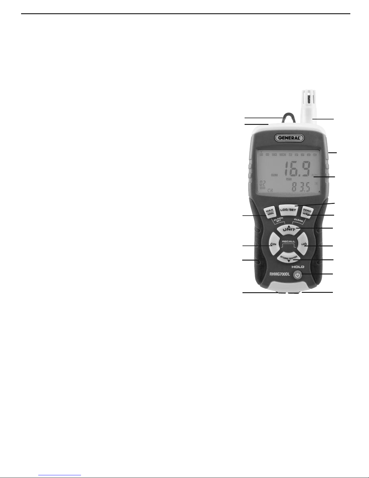
Fig. 1 shows the names and locations of all of the controls, connectors and physical structures of
the RHMG700DL. Fig. 2 shows all possible indications on the unit’s LCD. Familiarize yourself with
the labels, positions and functions of all buttons and connectors before moving on to the Setup
Instructions and Operating Instructions.
Fig. 1. The controls and physical structures of the RHMG700DL
A. Humidity/temperature sensor under protective cap
B. Removable hanger tab
C. Socket for optional “K” type thermocouple probe with spade
lugs
D. LCD
E.
LOG/SET
button. Starts and stops data logging.
Also used to view data logging settings.
F.
MAX/MIN
button. For all parameters except moisture level,
pressing button once displays highest reading
since
entering that measurement mode.
Pressing button twice
displays lowest reading
since entering that measurement
mode. Pressing button a third time resumes measurement
and display of same parameter.
Also used to enter alarm set mode.
G.
ZERO
button.
With meter off
, used to disable APO function.
In measurement mode, used to calibrate pinless moisture
(
Moisture Internal
or MI) measurements.
In memory and
data logging modes
, used to clear stored readings and
data.
H.
UNIT
button.
In measurement mode, each press toggles
between Imperial and metric
measurement units for the following parameters: Ambient
Temperature & Dew Point (°F or °C); Absolute Humidity (mg/L or g/m
3
); Mixing Ratio (GPP or
g/kg); Barometric Pressure and Vapor Pressure (mBAR or KPa).
In memory mode
, used to clear
stored readings.
Also used to enter alarm set mode
.
I.
<DN
button.
In measurement mode, each press shifts mode selector one position to the left.
In memory mode, each press decrements record counter
by one digit.
In alarm set mode, each
press decreases alarm setpoint by 0.1%
.
J.
UP>
button.
In measurement mode, each press shifts mode selector one position to the right.
In memory mode, each press increments record counter
by one digit.
In alarm set mode, each
press increases alarm setpoint
by 0.1%.
K.
STORE/ENTER
button.
In measurement mode, stores both displayed readings
in memory
when pressed and held for >2 seconds.
In alarm set mode, saves displayed Hi alarm setpoint
and advances to Lo alarm setting, or saves displayed Lo alarm setpoint and resumes
measurement mode.
In memory mode, exits memory mode
and resumes measurement and
display of last selected parameter.
5
O
A
RHMG700DL
B
C
F
I
M
P
D
G
H
J
K
L
N
E
Page 6
6
L.
HOLD
button.
With meter off
, pressing button powers it on.
With meter on
, pressing button
briefly freezes primary and secondary readouts; pressing and holding button powers meter off.
M. Jack for included pin-type moisture probe N. Mini-USB jack
O. Pinless moisture sensor (on back) P. Battery compartment (on back)
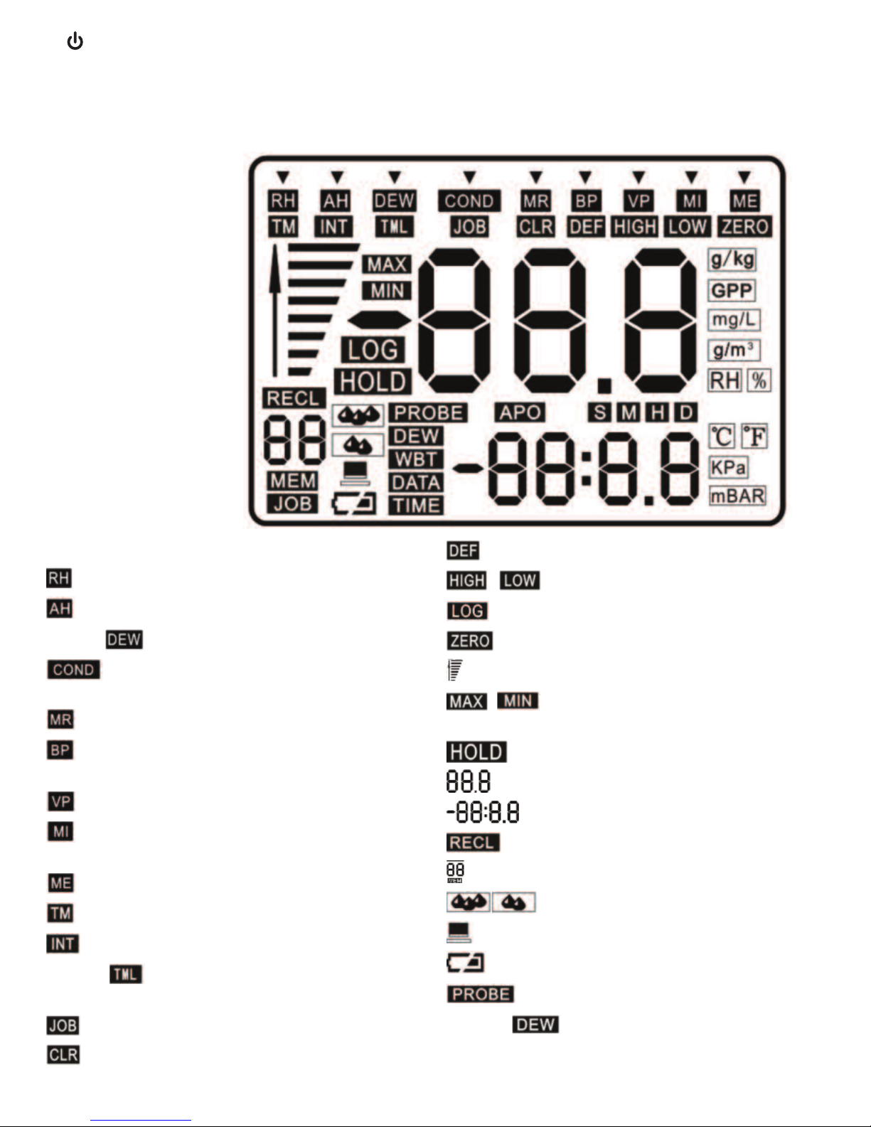
▼: Mode selector
: Relative humidity mode indicator
: Absolute humidity mode indicator
[Upper] : Dew point mode indicator
: Condensation temperature mode
indicator
: Mixing ratio mode indicator
: Barometric (ambient) pressure mode
indicator
: Vapor pressure mode indicator
: Pinless moisture measurement mode
indicator
: Pin-type moisture mode indicator
: Time setting indicator
: Data logging interval setting indicator
[Upper] : Data logging length setting
indicator
: Data log working group setting indicator
: Clear data logging setting indicator
: Default setting indicator
,
: Alarm limit indicators
: Data logging indicator
: Zero indicator
: Pin/pinless moisture level indicator
, : Maximum & minimum value
indicators
: Data hold indicator
: Primary readout
: Secondary readout
: Recall mode indicator
: Record number indicator
: Condensation level indicators
: USB connection indicator
:Low battery icon
: Probe indicator
[Lower] : Dew point temperature
indicator
L
.
M
N
/HOLD b
out of viewin
Mini USB
L
L
L
L
L
L
L
/HOLD button Press to power the unit on, press HOLD button for 2s to power off,
out of viewing mode.
M
Wood moisture probe interface
N
Mini USB interface
L
CD Display
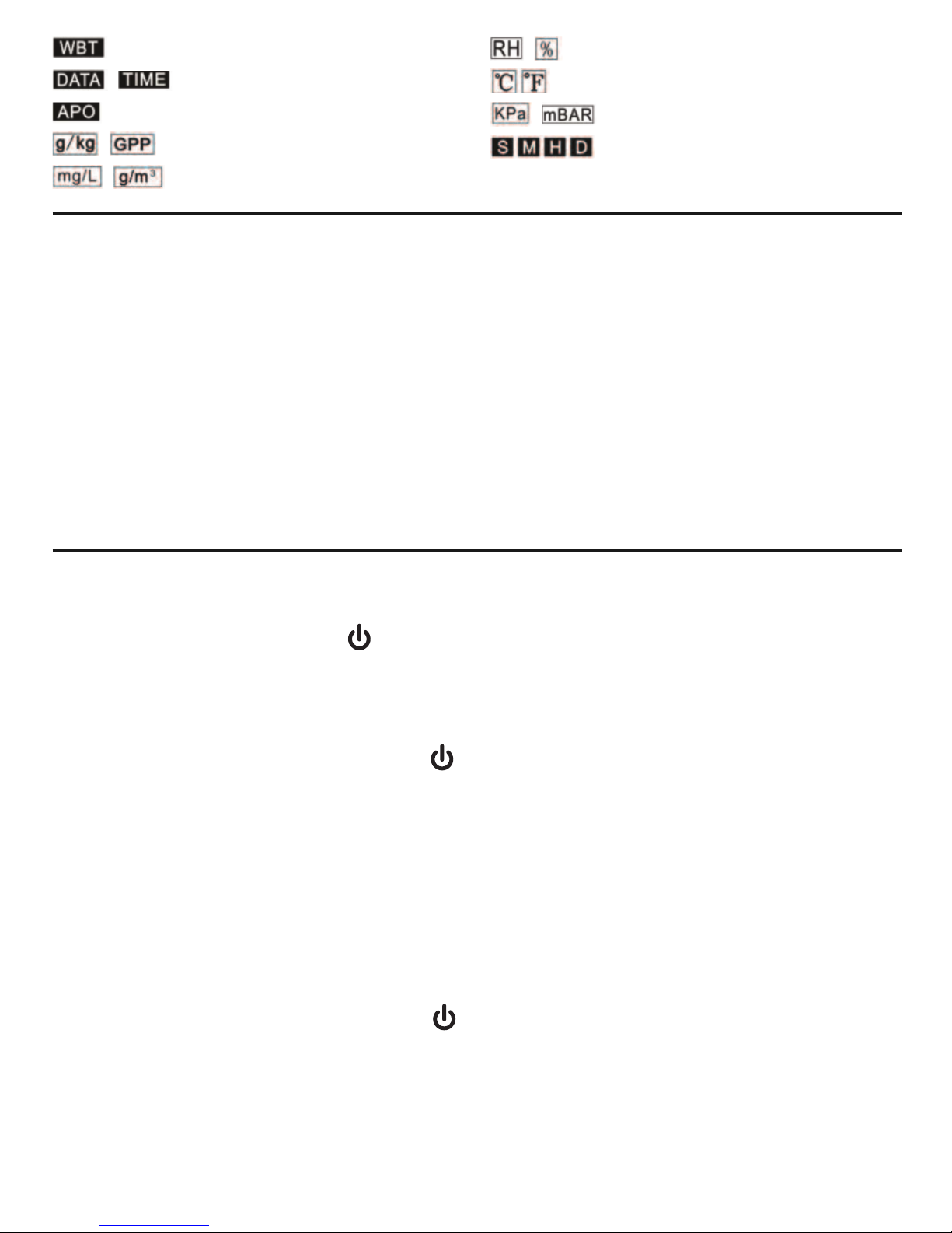
Fig. 2.
All possible
display
indications
Page 7
SETUP INSTRUCTIONS
INSTALL BATTERY
To open the battery compartment:
1) Turn the meter over and loosen the single screw securing the battery compartment cover.
Remove the screw and set it aside.
2) Lift the tab at the bottom of the cover in order to remove it and set it aside.
3) Plug the included “9V” battery into the wired socket inside the compartment. The terminals
of the battery and the socket mate in only one way, with the smaller male terminal plugging
into the larger female terminal.
4) Replace the battery compartment cover and reinstall the screw to secure the cover.
OPERATING INSTRUCTIONS
POWERING ON & OFF
To power on the meter
, press the
HOLD
button. By default, the instrument will immediately
begin making and displaying RH (relative humidity) measurements.
Before using the meter
to make measurements, remove the dust cap protecting the
humidity/temperature sensor.
To power off the meter
, press and hold the
HOLD
button for at least 2 seconds. The shutdown
will be announced by two short beeps.
After powering off the meter, replace the sensor protection cap if you do not expect to use the
instrument within the next few hours.
By default, the meter will automatically power itself off if no front-panel button is pressed within
any 30-minute period. The upcoming shutdown will be announced by three beeps of the beeper.
When this Auto Power Off function is active, the term
APO
will appear in the middle of the LCD
(see Fig. 2).
To disable the APO function
, you must power on the meter in a special way, by pressing and
holding the
ZERO
button while pressing the
HOLD
button. When the APO function has been
disabled, the term
APO
will
not
appear on the LCD.
7
: Web bulb temperature indicator
,
: Date and Time indicators
: Auto power off enabled indicator
, : Mixing ratio units
, : Absolute humidity units
,
:
Relative humidity unit
: Temperature units
, : Pressure units
:Seconds, minutes, hour, day
indicators
Page 8

8
SELECTING A PARAMETER
The RHMG700DL can measure and display the value of multiple
moisture-related parameters. When the meter is in measurement
mode, you select a parameter by pressing either the
UP>
or
<DN
button to move the ▼ pointer on the top line of the LCD directly
above it. For example, at right is the display for RH measurement
mode—the operating mode that the meter enters by default when
it is powered on.
As the lower figure at right shows, moving the ▼ pointer one
position to the right (by pressing the
UP>
button once) changes the
measured parameter to AH (absolute humidity).
GENERAL CONTROLS
Changing measurement units
. By default, the RHMG700DL uses
Imperial units for all parametric readouts.
To switch to metric units
, press the
UNIT
button.
Ambient, wet bulb and dew point temperatures will then be displayed as °C rather than °F;
absolute humidity values will be stated in g/m
3
rather than in mg/L; mixing ratios will be
displayed in units of g/kg rather than GPP; and barometric pressures and vapor pressures will be
stated in KPa rather than mBAR.
Backlight
. The RHMG700DL has a green backlight that automatically illuminates whenever any
button is pressed. It will remain on for 30 seconds and then extinguish to extend battery life.
Holding readings. Briefly
pressing the
HOLD
button freezes both
the primary and secondary readouts. will appear on the
display to remind you that the readouts are frozen.
To release the hold, briefly press the
HOLD
button again.
Note: When the RHMG700DL is in Hold mode, it takes two separate
presses of the
HOLD
button to power off the meter. The first
(brief) press (accompanied by a short beep) releases the hold. The
second press (and hold) initiates shutdown (announced by two short beeps).
Storing readings
. Pressing and holding the
STORE/ENTER
button for at least 2 seconds saves the
values shown on the primary and secondary readouts as a pair in the meter’s nonvolatile
memory. Each “save” automatically increases by one the Record number indicator—the number
above
MEM
at the lower left of the LCD. The readings remain in memory, available for recall, after
the meter powers off.
The next section of this manual contains instructions for recalling
saved readings.
MIN/MAX tracking
. For all parameters except moisture level:
•
Pressing the MAX/MIN button once displays the highest
reading
since entering that measurement mode. will
appear at the left of the primary readout.
L
/HOLD b
out of viewin
Page 9

•
Pressing the button twice displays the lowest reading
since
entering that measurement mode. will appear at the left of
the primary readout.
•
Pressing the button a third time resumes real-time
measurement
and display of the same parameter.
RECALLING STORED READINGS
To enter Recall mode
, press the
<DN
and
UP>
buttons at the same time. will appear
above the Record number indicator at the lower left of the LCD. The Record number indicator will
correspond to the last pair of readings stored.
You can now use the
<DN
and
UP>
buttons to navigate to and display a specific pair of readings.
For example, the screen shot below shows that a pair of readings of 63.8% for RH and 28.8°C for
temperature were stored in Record location 08.
Alternatively, you can repeatedly press the
UP>
button to recall all
readings in the order in which they were stored, or the
<DN
button
to recall them in reverse order. Pressing the
UP>
button when the
last stored pair of readings is displayed returns the Record
number indicator to
01
, corresponding to the first pair of readings
stored. Pressing the
<DN
button when the first stored pair of
readings is displayed returns the indicator to the record number of
the last pair of readings stored.
To exit Recall mod
e and resume making real-time measurements, press the
STORE/ENTER
button.
To erase all stored readings
, press and hold the
ZERO
and
UNIT
buttons at the same time for at least 2 seconds. The meter will
respond by sounding three short beeps and resetting the Record
number to
01
. You can clear all stored readings while operating in
Recall mode or Measurement mode. Clearing the memory in
Recall mode produces the display at right.
SETTING ALARMS
Note: Follow the instructions in this section to manually set, change or arm/disable the RH and
moisture level alarms using buttons on the meter. To perform the same tasks using the X-In-1
software included with the meter, install and operate the program using the instructions in the
“Using the Included Software” section beginning on p. 15.
The RHMG700DL allows you to set alarms that will repeatedly
sound the beeper if the measured RH level or the moisture level of
a material (measured by either the pinless or pin-type sensor) is
above or below a certain value. The upper and lower limits are
called alarm setpoints. For example, the screen shot at right shows
that the upper limit for RH—the
HIGH
setpoint of the RH alarm—
has been set to 63.8%.
Wood moisture pro
Mini USB
L
9
Page 10

To enter Alarm set mode
, press the
MAX/MIN
and
UNIT
buttons at the same time while in
RH,
MOISTURE INTERNAL (MI)
or
MOISTURE EXTERNAL (ME)
mode. Doing so will display the current
value of the selected parameter’s high setpoint and cause the word
HIGH
to appear on the
display, as shown in the screen shot at the bottom of the previous page.
All three parameters require you to use the same three-step sequence of button presses for
changing their setpoint(s). After entering Alarm set mode (with
HIGH
appearing on-screen), you
can either raise or lower the
HIGH
setpoint by using the
UP>
or
<DN
button, or leave it
unchanged (if you wish to change only the
LOW
setpoint). Each press of the
UP>
button increases
the setpoint by 0.1%. Each press of the
<DN
button decreases the setpoint by 0.1%. To change
the value of the setpoint by a large amount, you can press and hold the
UP>
or
<DN
button for at
least 3 seconds.
Whether or not you change the
HIGH
setpoint, you must press the
STORE/ENTER
button to
proceed to the next step in the sequence: changing the
LOW
setpoint. Pressing the
STORE/ENTER
button with
HIGH
on-screen saves the value shown on the primary readout as the selected
parameter’s new
HIGH
setpoint. It also changes
HIGH
to
LOW
and switches the primary readout to
show the current value of the parameter’s
LOW
setpoint.
Once
LOW
appears on-screen, you can use the
UP>
or
<DN
button to change the value of the
parameter’s
LOW
setpoint, as explained earlier in the paragraph on
HIGH
setpoints. Alternatively,
you can leave the
LOW
setpoint unchanged. Whether or not you make a change, your next step
must be to press the
STORE/ENTER
button. Doing so saves the value shown on the primary
readout as the selected parameter’s new
LOW
setpoint. It also causes
LOW
to disappear and
returns the RHMG700DL to operation in real-time RH measurement mode.
To disarm any of the six alarms(HIGH
and
LOW
for RH, MIand ME), you must reset its setpoint to
100.0% or 0.0% by pressing the
UP>
or
<DN
button. When disarming a
HIGH
alarm, it is faster to
use the
UP>
button to increase its setpoint to 100% than to use the
<DN
button to decrease its
setpoint to 0.0%. In practice, what you would do is: 1) press and hold the
UP>
button until the
display shows a value greater than 99%, 2) release the button, and 3) use brief presses to reach
99.9%. When the primary readout shows 99.9%, the next press of the
UP>
button will change
the readout to
OFF
. Pressing the
STORE/ENTER
button at this point will disarm the
HIGH
alarm for
that parameter.
Similarly, you would disarm a
LOW
alarm by 1) pressing and holding the
<DN
button until the
display shows a value less than 1%, 2) releasing the button, and 3) using brief presses to reach
0.1%. When the primary readout shows 0.1%, the next press of the
<DN
button will change the
readout to
OFF
. Pressing the
STORE/ENTER
button at this point will disarm the
LOW
alarm for that
parameter. The screen below right shows the next-to-last step (prior to pressing the
STORE/ENTER
button) of disarming the
LOW
alarm for RH.
Two notes related to alarms:
1)
HIGH
alarm setpoints must be higher than
LOW
alarm setpoints.
When the display is showing
LOW
in Alarm set mode, pressing
the
STORE/ENTER
button to save a change that violates this
rule will not succeed in returning the RHMG700DL to real-time
measurement. Instead, the beeper will sound four times and the
10
Page 11

11
Alarm set sequence will return to the first step. Consider this a prompt to reset the
HIGH
alarm
setpoint to a value greater than the
LOW
alarm setpoint.
2) The original factory settings of the
HIGH
and
LOW
alarm setpoints are 85% and 25%,
respectively. So if your first use of the meter is in a exceptionally humid or dry environment, an
alarm may sound immediately. To disarm the alarm, follow the instructions in the preceding
two paragraphs.
MEASURING MOISTURE LEVELS
In addition to the modes for measuring five condensation-related parameters, the RHMG700DL
has two separate moisture level measurement modes:
MI
and ME. In MI mode, the meter uses a
non-invasive (pinless) sensor on the back of the unit to detect moisture on or within 0.75 in.
(19mm) of the surface of a material. In
ME
mode, the meter uses the included pin-type probe to
measure the conductivity of a material as a proxy for its moisture content.
In both moisture level measurement modes, the RHMG700DL’s display adds a vertical bar graph
to the digital readout of a material’s moisture level. The bar graphs (see below) have no scale;
they exist only to provide an analog way to quickly track changes in relative moisture levels.
To use the included pin-type probe to measure the moisture level of a material:
1. Use the
UP>
or
<DN
button to move the ▼ pointer above ME.
2. Insert the plug of the probe into the jack on the bottom of the RHMG700DL.
3. Remove the protective cap from the business end of the probe and set it aside.
4. Insert the pins of the probe into the material whose moisture level you wish to measure.
The measured moisture level will appear on the primary readout as a percentage, with the
ambient temperature below it on the secondary readout.
To use the pinless sensor to measure the moisture level of a material
, use the
UP>
or
<DN
button to move the ▼ pointer above MI. Hold the meter in either hand by wrapping your fingers
around the rubber grip at the bottom of the unit. Make sure that no part of your hand or fingers is
touching—or even near—the pinless sensor on the back of the meter.
If the primary readout shows
0.0%
with the meter in your hand (and not touching anything), the
meter is ready to make measurements. To measure the moisture level of a material, press the
pinless sensor on the back of the meter (Fig. 1, Callout M) against it. The moisture level, as a
percentage, will appear on the primary readout.
Page 12

12
If the primary readout shows a value other than
0.0%
, you must
calibrate the meter to operate in
MI
mode. To do so, continue to
hold the meter in your hand (touching nothing) and press the
ZERO
button. Immediately after the term
ZERO
appears briefly below the
bar graph at the left of the display, the primary readout will show
0.0%
and the meter will be calibrated and ready to operate in
MI
mode.
To obtain accurate readings in
MI
mode, you must recalibrate the meter each time you re-enter
that mode from another mode.
CHECKING CALIBRATION
Although you cannot calibrate the RHMG700DL yourself, you can
check
the meter’s calibration
periodically to assure yourself of the accuracy of humidity-related readings (RH, absolute
humidity, dew point and mixing ratio). Factory calibration should minimize the humidity sensor’s
drift for several years—well beyond the warranty period.
At a minimum, a calibration check should entail immersing the slotted structure protecting the
humidity sensor in two bottles containing saturated salts. One reference salt should produce a
reading of a 33%; the other should produce a reading of 75%.
Two salts of this type are available from General: the HR33LJ (33%) MgCl Calibration Salt and the
HR75LJ (75%) NaCl Calibration Salt.
Depending on the size and shape of the calibration salt bottle that you use, you may have to
remove the hanger tab (Fig. 1, Callout B) from the meter to provide sufficient clearance for the
bottle to fit snugly over the slotted structure protecting the humidity/temperature sensor (after
removing the dust cap). The hanger tab is removable for that reason.
DATA LOGGING
This section explains how to use front-panel buttons on the RHMG700DL to view and manually
change data logging settings and to clear logged data from the meter's memory.
The final section of this manual—
Using the Included Software
, beginning on p. 15—outlines how
to do the same tasks more quickly and easily by pressing soft buttons on the X-In-1 application
included with the meter.
Viewing Data Logging Settings
To view your data logging settings
, press the
LOG/SET
button. If
the ▼ mode selector does not appear above
TM
, press the
<DN
or
UP>
button to move the selector above TM, at the left side of the
top line of the display. Once the selector is above
TM
, the two-digit
date portion of the system clock setting (09:18, or September 18,
2012 in the upper screen shot at right) will be visible on the
secondary readout.
Page 13

13
To show the time portion of the system clock setting, press the
UNIT
or
STORE/ENTER
button with the date value on-screen. In the lower
screen shot at right, the time shown is 19:18:12 (7:18:12 p.m.)
Next, press the
UP>
button to shift the ▼ icon one position to the
right, above
INT
.
Doing so will shift the secondary display to the value of the auto
recording time interval
INT
. Press the
UP>
button once more to display the recording time length
TML
, and then again to display the working group
JOB
number.
To stop displaying data logging settings and return to showing real-time readings, press the
HOLD
button.
Changing Data Logging Settings
To reset the system clock
, begin by pressing the
LOG/SET
button and making sure the ▼ mode
selector is positioned over
TM
.
With
DATA
showing on-screen, press the
LOG/SET
button. This will cause the Year field at the left
side of the LCD to begin flashing. To increment the Year value, press the
UNIT
button. To
decrement the Year value, press the
STORE/ENTER
button.
When the Year value is correct, press the
LOG/SET
button to save the setting and advance to the
Month field, which should now be flashing. Use the
UNIT
or
STORE/ENTER
button to correct the
Month setting. Then press the
LOG/SET
button to save the setting and advance to the Day field.
Again use the
UNIT
or
STORE/ENTER
button to correct the Day value and press the
LOG/SET
button to save the setting.
Pressing the
LOG/SET
button with the Day value of the system clock flashing switches the
secondary display to show the current time. As you did with the Date, use the
UNIT
or
STORE/ENTER
button to correct each of the Hour, Minutes and Seconds values in turn. Once you
have finished setting the system clock, press the
LOG/SET
button to save the setting. Complete
the process by pressing the
HOLD
button to return to displaying real-time readings.
To change the value of the data logging time interval INT
:
● Press the
LOG/SET
button to enter viewing and setting mode
● Move the ▼ mode selector over
INT
.
● Press the
LOG/SET
button again. This will cause the two digits on the secondary display to
flash.
Page 14

● Use the
UNIT
button to increase the
INT
value or the
STORE/ENTER
button to decrement it.
The default value of
INT
is 15 seconds. It is also the minimum possible value. The maximum
possible value is 24 hours. The terms
S, M
and Hon the line above the
INT
value stand for
seconds, minutes and hours, respectively. If you press and hold the
UNIT
or
STORE/ENTER
button, you can ramp up or down quickly to any possible value. The seconds, minutes and
hours indicators will automatically change as you ramp up and down.
● When you have finished changing the value of
INT
, press the
LOG/SET
button to save your
setting.
● Complete the process by pressing the
HOLD
button to return to displaying real-time
readings.
To change the value of the data logging time length setting TML:
● Press the
LOG/SET
button to enter viewing and setting mode.
● Move the ▼ mode selector over
TML
.
● Press the
LOG/SET
button again. This will cause the two digits on the secondary display to
flash.
● Use the
UNIT
button to increment the
TML
value or the
STORE/ENTER
button to decrement it.
The default value of
TML
is 15 minutes. The minimum possible value is 1 minute, and the
maximum possible value is 30 days. It’s important to understand that the value of
TML
must
be greater than that of
INT
. The terms
D, H
and Mon the line above the
TML
value stand for
days, hours and minutes, respectively. If you press and hold the
UNIT
or
STORE/ENTER
button, you can ramp up or down quickly to any possible value. The days, hours and minutes
indicators will automatically change as you ramp up and down.
● When you have finished changing the value of
TML
, press the
LOG/SET
button to save your
setting.
● Complete the process by pressing the
HOLD
button to return to displaying real-time
readings.
CLEARING DATA LOGS
To clear all stored data logs:
● Press the
LOG/SET
button to enter viewing and setting mode.
● Move the ▼ mode selector over
CLR
(see screen shot at
right).
● Press and hold the
ZERO
button for at least 2 seconds. The screen below left will appear
briefly, followed by the screen
below right. All stored data logs
will be erased and the number of
the
JOB
working group will be
reset to
01
.
14
Page 15

● Complete the process by pressing the
HOLD
button to return to displaying real-time
readings.
Starting and Stopping Data Logging
To initiate data logging
, make sure the RHMG700DL is
not
operating in settings viewing or changing mode. Then disable the
meter’s Auto Power Off (APO) function by pressing and holding
the
ZERO
button while pressing the /
HOLD
button. Next, press
and hold the
LOG/SET
button for at least 2 seconds. The terms
LOG
and
JOB
and the current real-time data readout will appear
on-screen.
The unit will begin logging data according to stored settings. Note that the term
APO
has
disappeared from the screen, indicating that the meter’s Auto Power Off function has been
disabled.
To stop data logging
, press and hold the
LOG/SET
button for at least 2 seconds. The terms
LOG
and
JOB
will disappear from the screen.
Each time logging is started or stopped, the
JOB
working group number will automatically be
increased by 1 up to a maximum of 99 groups. When 98 groups have been stored, the term
JOB
will be replaced by the term
FL
(full). Additional logging cannot occur until existing logs are
cleared.
USING THE INCLUDED SOFTWARE
The main purpose of the X-In-1 application on the mini-disc supplied with the RHMG700DL is to
display data logs captured and stored by the meter. The program’s secondary function is to make
it easy to set the meter’s system clock and to change its data logging settings and temperature
and moisture alarm setpoints.
To install the X-In-1 program
, place the mini-disc face-up in the tray of your computer’s optical
drive, open the <Volume> folder, and double-click the <setup.exe> file. Run the installation
Wizard, which will also automatically locate and install the correct driver for your PC’s operating
system.
After the program installs, do not open it yet. First, connect the RHMG700DL to your computer by
inserting the mini-plug end of the included USB cable into the mini-USB jack on the bottom of the
meter (Fig. 1, Callout N) and inserting the full-size plug at the other end of the cable into a USB
port of your computer. Note that inserting the cable causes the icon to appear on the meter’s
LCD.
The icon indicates that a two-way link has been established between the meter and the software.
Working in one direction, the link enables data logs stored in the meter to be downloaded to your
PC and displayed by the program as a table or graph. Working in the opposite direction, the link
allows you to set the system clock and change data logging and alarm settings using your mouse
and have those changes reflected inside the meter.
L
15
Page 16

It’s important to realize that
data logging cannot be started or stopped while the RHMG700DL is
connected
to your PC.
Now open the X-In-1 program. The screen shot below shows the main area for displaying a data
log as a graph or table (list). Above this area are boxes you can check to select which logged
parameters you wish to display. At the upper left side of the screen are circles you can check to
select the units of key measurement parameters. Below these circles are six boxes for manually
entering high and low (Min and Max) RH and Moisture alarms and the data logging sampling
interval and run time. Below those circles are four buttons, including one (SynTime) for
synchronizing the RHMG700DL’s system clock to your computer's clock, and another for
Downloading data logs from the meter to your PC.
16
Page 17

SPECIFICATIONS
Ambient Temperature Measurement Range -20° to 167°F (-29° to 75°C)
Ambient Temperature Measurement Accuracy ±3.6°F (2°C)
RH Measurement Range 0 to 100%
RH Measurement Accuracy ±2.5% from 11 to 90%RH; ±3%RH elsewhere
Absolute Humidity Range 0.5 to 240mg/m3(mg/L)
GPP Range 0 to 999 GPP (0 to 160g/kg)
Relative/Absolute Moisture Level Range 0 to 99.9%
Pinless Moisture Measurement Depth 0.75 in. (19mm)
Dew Point Range -76° to 140°F (-60° to 60°C)
Atmospheric Pressure Range 30 to 120 kPA
Vapor Pressure Range 0 to 20.0 kPA
Sampling Rate 2X/sec
Memory Capacity 20 pairs of readings
Auto Power Off Trigger 30 minutes of inactivity
Backlight Duration 30 seconds
Battery Life 6 to 8 weeks (4 hrs/day use)
Operating Temperature 32° to 110°F (0° to 43°C)
Storage Temperature -14° to 140°F (-30° to 60°C)
Dimensions 7.3 x 2.8 x 1.4 in. (185 × 72 × 36mm)
Weight 6.2 oz. (175g), without battery
Power Source (1) “9V” battery (included)
17
Page 18

OPERATING & MAINTENANCE TIPS
• When the icon appears on the bottom left of the LCD, it’s time to install a fresh “9V”
battery using the procedure on p. 7.
• Do not immerse the RHMG700DL in water or get water on it.
• Do not disassemble the unit. Opening the case voids the warranty.
• To avoid fouling the humidity/temperature sensor, do not operate the unit in very dusty
environments. Rotate the sensor protective cap to close the vents after each measurement
session.
• Remove the battery if you do not expect to use the unit for several months or longer.
This will avoid potential leaks of battery acid that might damage or destroy the unit.
WARRANTY INFORMATION
General Tools & Instruments’ (General’s) RHMG700DL 14-in-1 Data Logging Thermo-Hygrometer
with Pin/Pinless Moisture Meter is warranted to the original purchaser to be free from defects in
material and workmanship for a period of one year. Subject to certain restrictions, General will
repair or replace this instrument if, after examination, the company determines it to be defective
in material or workmanship. The warranty period begins on the date of purchase. You are
encouraged to register your product online. General will extend your warranty an additional
60 days if you register at www.generaltools.com/ProductRegistry.
This warranty does not apply to damages that General determines to be from an attempted repair
by non-authorized personnel or misuse, alterations, normal wear and tear, or accidental damage.
The defective unit must be returned to General Tools & Instruments or to a General-authorized
service center, freight prepaid and insured.
Acceptance of the exclusive repair and replacement remedies described herein is a condition of
the contract for purchase of this product. In no event shall General be liable for any incidental,
special, consequential or punitive damages, or for any cost, attorneys’ fees, expenses, or losses
alleged to be a consequence of damage due to failure of, or defect in any product including, but
not limited to, any claims for loss of profits.
Register now at www.generaltools.com/ProductRegistry to receive a 60-day extension to your
warranty.
18
Page 19

RETURN FOR REPAIR POLICY
Every effort has been made to provide you with a reliable product of superior quality. However, in
the event your instrument requires repair, please contact our Customer Service to obtain an RGA
(Return Goods Authorization) number before forwarding the unit via prepaid freight to the
attention of our Service Center at this address:
General Tools & Instruments
80 White Street
New York, NY 10013
212-431-6100
Remember to include a copy of your proof of purchase, your return address, and your phone
number and/or e-mail address.
19
Page 20

20
Page 21

GENERAL TOOLS & INSTRUMENTS
80 White Street
New York, NY 10013-3567
PHONE (212) 431-6100
FAX (212) 431-6499
TOLL FREE (800) 697-8665
e-mail: sales@generaltools.com
www.generaltools.com
RHMG700DL User’s Manual
Specifications subject to change without notice
©2014 GENERAL TOOLS & INSTRUMENTS
NOTICE - WE ARE NOT RESPONSIBLE FOR TYPOGRAPHICAL ERRORS.
MAN# RHMG700DL
4/1/14
 Loading...