

Page 1

Gen-Eye™ Hot Spot™
Operator’s Manual
Issue 1.0 053-2672
ORIGINAL INSTRUCTION
Page 2

Gen-Eye™ Hot Spot™ Operator’s Manual Overview - 1
Overview
Chapter Contents
Serial Number Location . . . . . . . . . . . . . . . . . . . . . . 2
System Components . . . . . . . . . . . . . . . . . . . . . . . . 2
Intended Use . . . . . . . . . . . . . . . . . . . . . . . . . . . . . . 3
IEC Safety Definitions . . . . . . . . . . . . . . . . . . . . . . . 3
FCC Statement . . . . . . . . . . . . . . . . . . . . . . . . . . . . . 4
About This Manual . . . . . . . . . . . . . . . . . . . . . . . . . . 5
• Bulleted Lists . . . . . . . . . . . . . . . . . . . . . . . . . . . . . . . . . . . . . . . . . . . . . 5
• Numbered Lists . . . . . . . . . . . . . . . . . . . . . . . . . . . . . . . . . . . . . . . . . . . 5
CMW
®
Page 3
Overview - 2 Gen-Eye™ Hot Spot™ Operator’s Manual
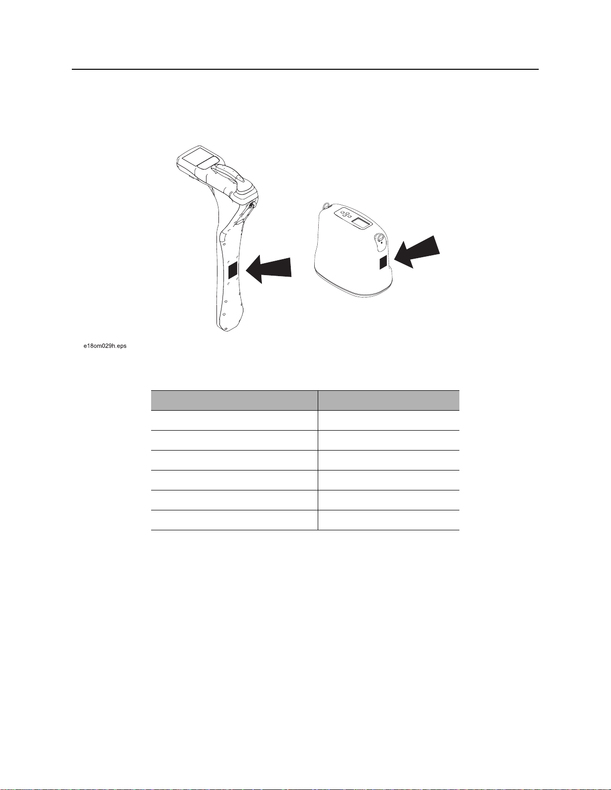
Serial Number Location
Serial Number Location
Record serial numbers and date of purchase in spaces provided. Unit serial number is located as shown.
Item
date of purchase:
receiver serial number:
transmitter serial number:
fault finder serial number:
accessory model & serial number:
accessory model & serial number:
System Components
Receiver (RX): Gen-Eye Hot Spot receiver with 10frequencies: 512B kHz, 1 kHz, 8 kHz, 33 kHz, 33B kHz,
50 kHz, 60 kHz, 65 kHz, 150 kHz, 180 kHz.
Transmitter (TX): Gen-Eye Hot Spot transmitter with 5-watt power output, 4 frequencies: 1 kHz, 8 kHz, 33,
kHz, 65 kHz.
CMW
®
Page 4

Gen-Eye™ Hot Spot™ Operator’s Manual Overview - 3
Intended Use
Intended Use
The Gen-Eye Hot Spot receiver is designed to locate buried pipes and cables. Twelve frequencies and four
modes of operation are available to suit your specific locating needs.
The Gen-Eye Hot Spot transmitter places a signal on target cables to be detected by Gen-Eye Hot Spot
receiver. The signal is placed through either direct connection, induction clamping, or broadcast mode.
The system is designed for operation in temperatures typically experienced in earth moving and
construction work environments. Use in any other way is considered contrary to the intended use. The
Gen-Eye Hot Spot system should be operated only by persons familiar with its particular characteristics
and acquainted with the relevant safety procedures. The system should be serviced only by authorized
repair centers.
IEC Safety Definitions
Hazardous voltage--electrical shock or equipment damage can result if transmitter is connected to
live cable. Have qualified utility personnel disconnect both ends of cable before working.
IEC protection class II or double insulated electrical device is one which has been designed in such
a way that it does not require a safety connection to electrical ground. In a device of this class, no
single failure can result in dangerous voltage becoming exposed so that it might cause an electrical
shock. This characteristic must be achieved without relying on a grounded metal casing.
CMW
®
Page 5

Overview - 4 Gen-Eye™ Hot Spot™ Operator’s Manual
FCC Statement
FCC Statement
This device complies with Part 15 of the FCC Rules. Operation is subject to the following two conditions:
(1) this device may not cause harmful interference, and (2) this device must accept any interference
received, including interference that may cause undesired operation.
Changes or modifications not expressly approved by The Charles Machine Works, Inc. could void the
user’s authority to operate the equipment.
This equipment has been tested and found to comply with the limits for a Class B digital device, pursuant
to Part 15 of the FCC Rules. These limits are designed to provide reasonable protection against harmful
interference in a residential installation. This equipment generates, uses, and can radiate radio frequency
energy and, if not installed and used in accordance with the instructions, may cause harmful interference
to radio communications. However, there is no guarantee that interference will not occur in a particular
installation. If this equipment does cause harmful interference to radio or television reception, which can be
determined by turning the equipment off and on, the user is encouraged to try to correct the interference by
one or more of the following measures:
• Reorient or relocate the receiving antenna.
• Increase the separation between the equipment and receiver.
• Connect the equipment into an outlet on a circuit different from that which the receiver is
connected.
• Consult the dealer or an experienced radio/TV technician for help.
FCC ID
The Gen-Eye Hot Spot may contain FCC ID: QOQWT41 and IC: 5123A-BGWT41.
CMW
®
Page 6

Gen-Eye™ Hot Spot™ Operator’s Manual Overview - 5
About This Manual
About This Manual
This manual contains information for the proper use of this equipment. Cross references such as “See
page 50” will direct you to detailed procedures.
Bulleted Lists
Bulleted lists provide helpful or important information or contain procedures that do not have to be
performed in a specific order.
Numbered Lists
Numbered lists contain illustration callouts or list steps that must be performed in order.
CMW
®
Page 7

Overview - 6 Gen-Eye™ Hot Spot™ Operator’s Manual
About This Manual
CMW
®
Page 8

Gen-Eye™ Hot Spot™ Operator’s Manual Foreword - 7
Foreword
This manual is an important part of your equipment. It provides safety information and operation
instructions to help you use and maintain your Gen-Eye Hot Spot equipment.
Read this manual before using your equipment. Keep it with the equipment at all times for future reference.
If you sell your equipment, be sure to give this manual to the new owner.
If you need a replacement copy, contact your Gen-Eye Hot Spot dealer. If you need assistance in locating
a dealer, call 800-245-6200 or 412-771-6300 or write to the following address:
General Pipe Cleaners
1101 Thompson Avenue
McKees Rocks, PA 15136 USA
The descriptions and specifications in this manual are subject to change without notice. The Charles
Machine Works, Inc. reserves the right to improve equipment. Some product improvements may have
taken place after this manual was published. For the latest equipment information see your Gen-Eye Hot
Spot dealer.
Thank you for buying and using Gen-Eye Hot Spot equipment.
CMW
®
Page 9

Foreword - 8 Gen-Eye™ Hot Spot™ Operator’s Manual
Gen-Eye™ Hot Spot™
Operator’s Manual
Issue number 1.0/OM-6/13
Part number 053-2672
Copyright 2013
by The Charles Machine Works, Inc.
CMW
®
Page 10
Gen-Eye™ Hot Spot™ Operator’s Manual Contents - 9
Contents
Overview
machine serial number, information about the type of work this machine is designed
to perform, basic machine components, and how to use this manual
Foreword
part number, revision level, and publication date of this manual, and factory contact
information
Safety
machine safety alerts and emergency procedures
Control Icons
control menus and display icon descriptions
Locate
procedures for locating active, passive and beacon signals
Service
service intervals and instructions for this machine
Specifications
machine specifications including weights, measurements and power rating
1
5
11
15
45
77
81
Support
the warranty policy for this machine, and procedures for obtaining warranty
consideration and training
63
CMW
®
Page 11

Contents - 10 Gen-Eye™ Hot Spot™ Operator’s Manual
CMW
®
Page 12

Gen-Eye™ Hot Spot™ Operator’s Manual Safety - 11
Safety
Chapter Contents
Guidelines . . . . . . . . . . . . . . . . . . . . . . . . . . . . . . . . 12
Safety Alert Classifications . . . . . . . . . . . . . . . . . . 13
Safety Alerts . . . . . . . . . . . . . . . . . . . . . . . . . . . . . . 14
CMW
®
Page 13

Safety - 12 Gen-Eye™ Hot Spot™ Operator’s Manual
Guidelines
Guidelines
Follow these guidelines before operating any jobsite equipment:
• Complete proper training and read operator’s manual before using equipment.
• Contact your local One-Call (811 in USA) or the One-Call referral number (888-258-0808 in USA and
Canada) to have underground utilities located before working. Also contact any utilities that do not
participate in the One-Call service. Classify jobsite based on its hazards and use correct tools and
machinery, safety equipment, and work methods for jobsite.
• Mark jobsite clearly and keep spectators away.
• Wear personal protective equipment.
• Review jobsite hazards, safety and emergency procedures, and individual responsibilities with all
personnel before work begins.
• Replace missing or damaged safety signs.
• Use equipment carefully. Stop operation and investigate anything that does not look or feel right.
• Contact your equipment dealer if you have any question about operation, maintenance, or equipment
use.
CMW
®
Page 14

Gen-Eye™ Hot Spot™ Operator’s Manual Safety - 13
Safety Alert Classifications
Safety Alert Classifications
These classifications and the icons defined on the following pages work together to alert you to situations
which could be harmful to you, jobsite bystanders or your equipment. When you see these words and
icons in the book or on the unit, carefully read and follow all instructions. YOUR SAFETY IS AT STAKE.
Watch for the three safety alert levels: DANGER, WARNING and CAUTION. Learn what each level
means.
indicates an imminently hazardous situation which, if not avoided, will result in death or
serious injury.
indicates a potentially hazardous situation which, if not avoided, could result in death or
serious injury.
indicates a potentially hazardous situation which, if not avoided, may result in minor or
moderate injury.
Watch for two other words: NOTICE and IMPORTANT.
NOTICE can keep you from doing something that might damage the unit or someone's property. It can also
alert you against unsafe practices.
IMPORTANT can help you do a better job or make your job easier in some way.
CMW
®
Page 15
Safety - 14 Gen-Eye™ Hot Spot™ Operator’s Manual
Safety Alerts
Safety Alerts
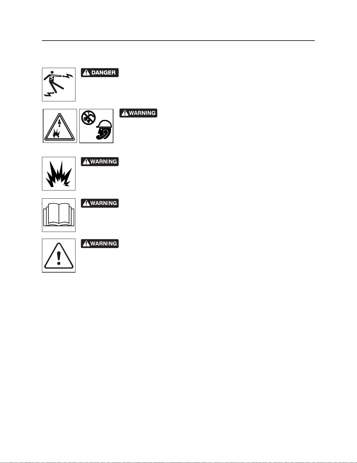
Electric shock. Contacting electric lines will cause death or serious injury.
Know location of lines and stay away.
Jobsite hazards could cause death or serious injury. Use
correct equipment and work methods. Use and maintain proper safety
equipment.
Explosion possible. Serious injury or equipment damage could occur.
Follow directions carefully.
Incorrect procedures could result in death, injury, or property damage.
Learn to use equipment correctly.
Moving traffic - hazardous situation. Death or serious injury could result.
Avoid moving vehicles, wear high visibility clothing, post appropriate warning signs.
CMW
®
Page 16
Gen-Eye™ Hot Spot™ Operator’s Manual Safety - 15
Safety Alert
Safety Alert
Read and follow all safety precautions.
Do not operate equipment unless you have completed proper training and have read the operator’s
manual.
Check that equipment is in good condition and that test leads are clean and have no cracked insulation.
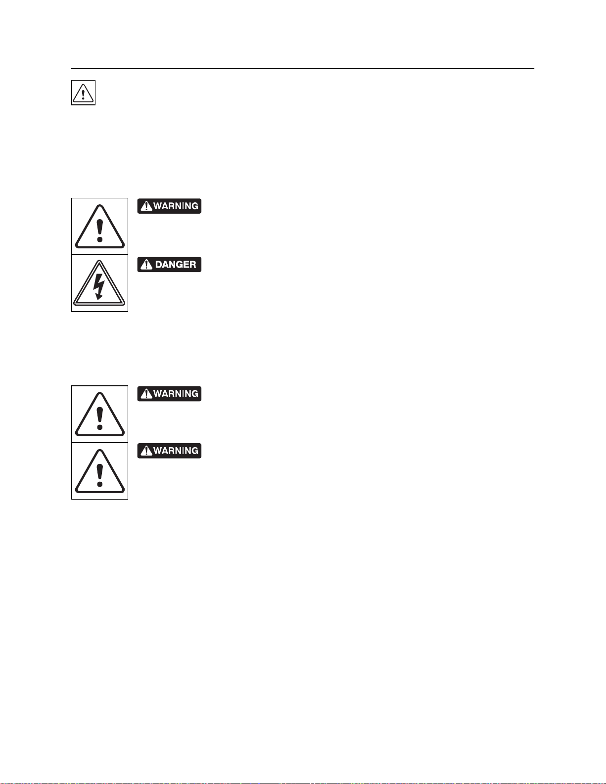
HIGH VOLTAGE. This device produces electric current that could cause
death or serious injury. Electric shock may result if you touch the clips on the HV output
cable. Use electrically insulating rubber gloves and proper procedures.
Electric shock or equipment damage can result if transmitter is connected to
live cable. Have qualified utility personnel disconnect both ends of cable before working.
Turn off transmitter when connecting or moving ground probe.
Jobsite hazards could cause death or serious injury. Use correct equipment and work methods. Use and
maintain proper safety equipment.
Explosion possible. Do not operate transmitter near explosive devices or
blasting operations.
Battery cells inside may vent or rupture. Do not crush, do not heat or
incinerate, do not short circuit, do not dismantle, do not immerse in any liquid. Observe
charging instructions.
CMW
®
Page 17

Safety - 16 Gen-Eye™ Hot Spot™ Operator’s Manual
Safety Alert
CMW
®
Page 18

Gen-Eye™ Hot Spot™ Operator’s Manual Control Icons - 17
Control Icons
Chapter Contents
Receiver . . . . . . . . . . . . . . . . . . . . . . . . . . . . . . . . . 18
• Keypad . . . . . . . . . . . . . . . . . . . . . . . . . . . . . . . . . . . . . . . . . . . . . . . . . 18
• Display . . . . . . . . . . . . . . . . . . . . . . . . . . . . . . . . . . . . . . . . . . . . . . . . . 19
• Menus . . . . . . . . . . . . . . . . . . . . . . . . . . . . . . . . . . . . . . . . . . . . . . . . . . 20
Transmitter . . . . . . . . . . . . . . . . . . . . . . . . . . . . . . . 21
• Keypad . . . . . . . . . . . . . . . . . . . . . . . . . . . . . . . . . . . . . . . . . . . . . . . . . 21
• Display . . . . . . . . . . . . . . . . . . . . . . . . . . . . . . . . . . . . . . . . . . . . . . . . . 22
• Menus . . . . . . . . . . . . . . . . . . . . . . . . . . . . . . . . . . . . . . . . . . . . . . . . . . 23
CMW
®
Page 19
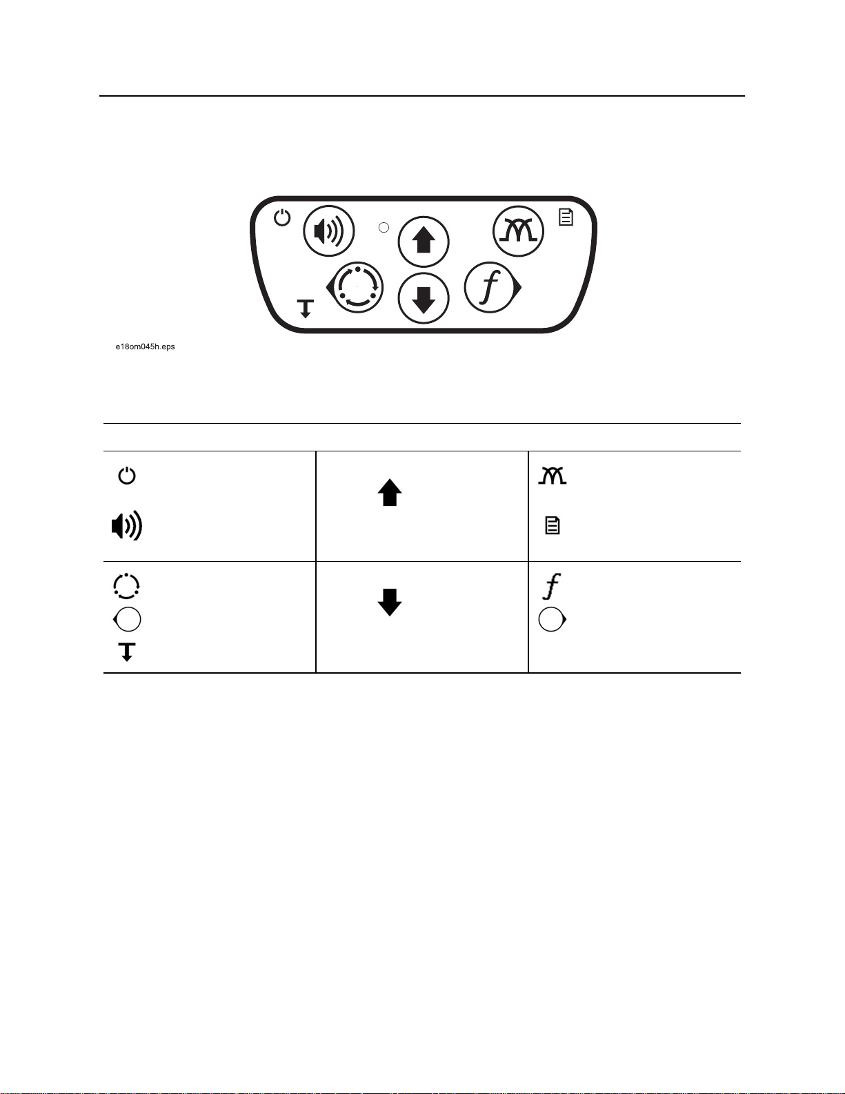
Control Icons - 18 Gen-Eye™ Hot Spot™ Operator’s Manual
Receiver
Receiver
Receiver Keypad
Keypad buttons perform several functions depending on operating mode. To activate most functions, press
and release the button. For other functions, press and hold the button until the function activates.
Receiver Keypad Icons
Power ON/OFF
(press and hold)
Volume
Exit Menu
Location Mode
Back
Depth
(press and hold)
Up
Down
Antenna Configuration
Menu
(press and hold)
Frequency
Select / Next
CMW
®
Page 20
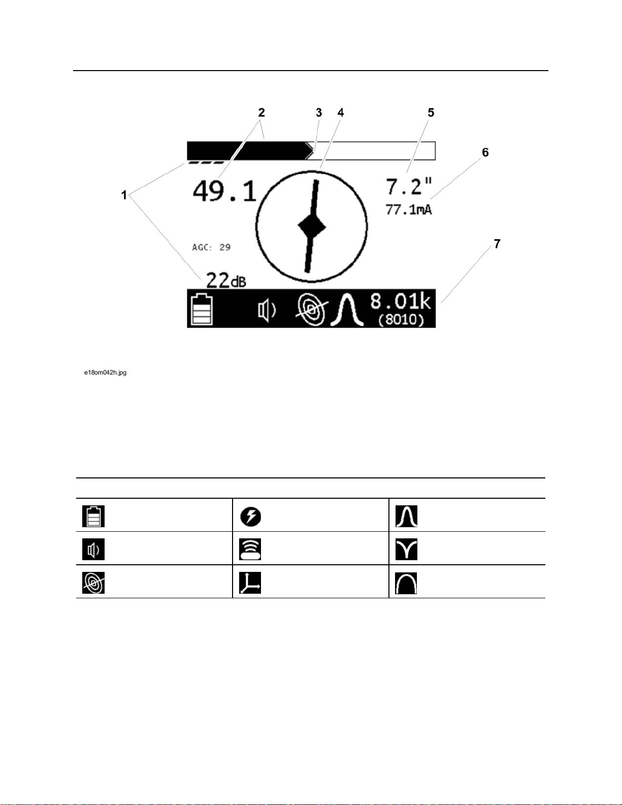
Gen-Eye™ Hot Spot™ Operator’s Manual Control Icons - 19
Receiver
Receiver Display
1. Gain
2. Signal strength
3. Peak signal
4. Compass
Status Bar Icons
Battery level Power mode Twin peak antenna
Volume level Beacon mode Null antenna
Line mode Total field antenna Single peak antenna
5. Estimated depth
6. Current meter
7. Unit status bar (see below)
CMW
®
Page 21
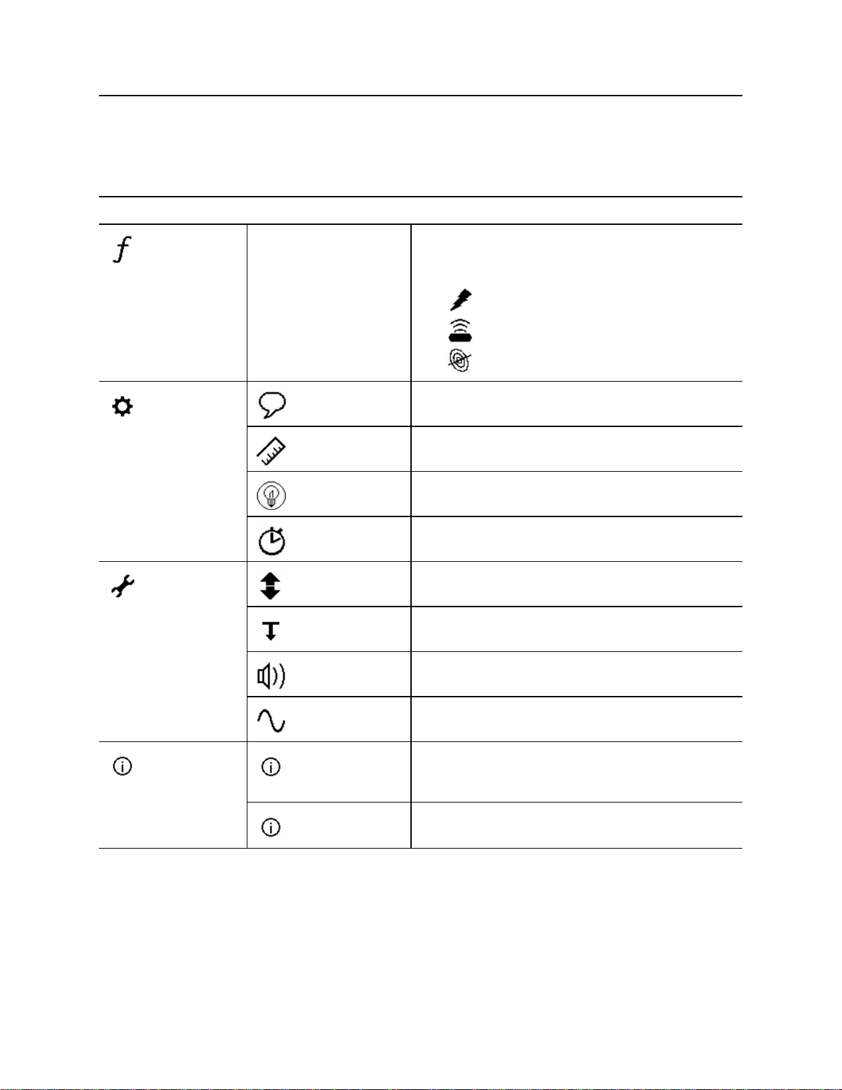
Control Icons - 20 Gen-Eye™ Hot Spot™ Operator’s Manual
Receiver
Receiver Menus
Menus allow the operator to set user interface preferences. Use the up, down, select/next, and back
buttons on the keypad to navigate the menu.
Receiver Menu Icons
Frequency Select frequencies to
activate.
Settings Language Select user interface language
Units Select measurement units for distance and depth
Backlight Select backlight setting
Shutdown Timer Set amount of time before unit shuts off
Options Gain Select gain option
Autodepth Select automatic or manual depth
Icons show which mode is suited for each
frequency:
Power
Beacon
Line
CMW
System
Information
®
Audio Mode Select audio mode setting
Audio Style Select audio style setting
System Info Displays the receiver model configuration, model
number, serial number, software version, hour
count, configuration date, and calibration date.
Diagnostics Use to troubleshoot receiver. Contact Product
support.
Page 22
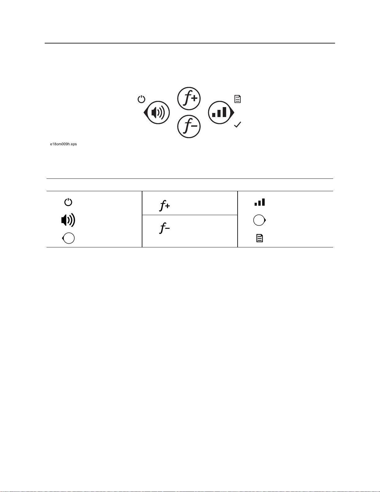
Gen-Eye™ Hot Spot™ Operator’s Manual Control Icons - 21
Transmitter
Transmitter
Transmitter Keypad
Keypad buttons perform several functions depending on operating mode. To activate most functions, press
and release the button. For other functions, press and hold the button until the function activates.
Transmitter Keypad Icons
Power ON/OFF
(press and hold)
Volume
Back
Frequency / Up
Frequency / Down
Power output
Select / Next
Menu
(Press and hold)
CMW
®
Page 23
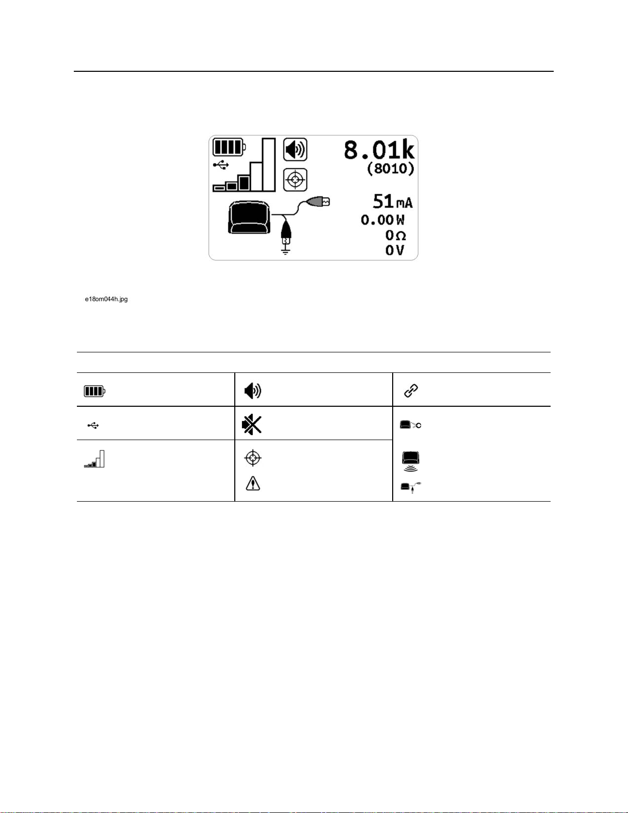
Control Icons - 22 Gen-Eye™ Hot Spot™ Operator’s Manual
Transmitter
Transmitter Display
The transmitter display shows the status of selected options as well as the active frequency and meter
reading.
Transmitter Display Icons
Battery level Volume on Linked to receiver
USB connected Volume off Inductive clamp
connected
Output power level Output active
Output interrupted
Induction active
Direct-connect leads
connected
CMW
®
Page 24
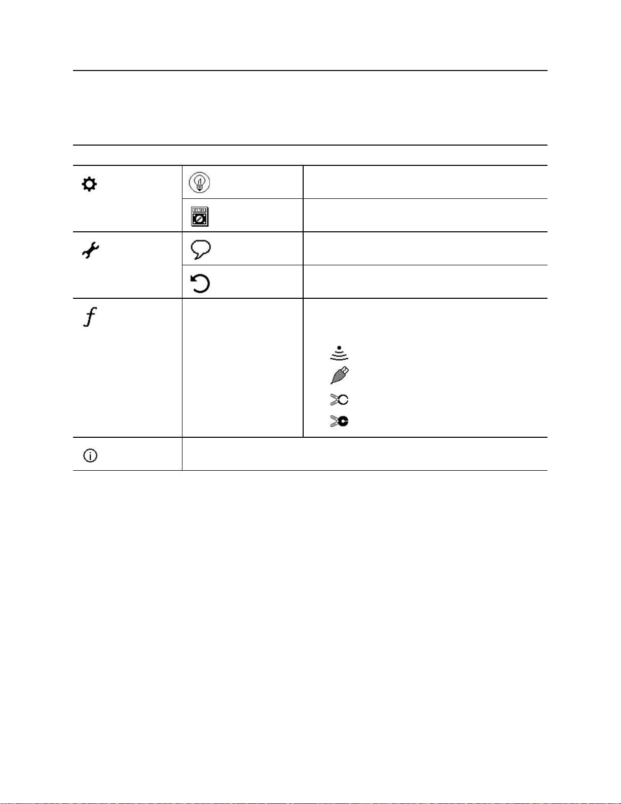
Gen-Eye™ Hot Spot™ Operator’s Manual Control Icons - 23
Transmitter Menus
Menus allow the operator to set user interface preferences. Use the up, down, select/next, and back
keypad buttons to navigate the menu.
Transmitter Menu Icons
Settings Backlight Select backlight setting
Meter Select meter setting
Options Language Select user interface language
Defaults Restores unit to factory default settings.
Frequencies Select frequencies to
activate.
System
Information
Displays the unit model configuration, model number, serial number, software
version, hour count, configuration date, and calibration date.
Icons show which connection can be used for each
frequency:
Induction
Direct connect
Induction clamp, standard
Induction clamp, low frequency
CMW
®
Page 25

Control Icons - 24 Gen-Eye™ Hot Spot™ Operator’s Manual
CMW
®
Page 26

Gen-Eye™ Hot Spot™ Operator’s Manual Locate - 25
Locate
Chapter Contents
Prepare. . . . . . . . . . . . . . . . . . . . . . . . . . . . . . . . . . . 26
• Select Signal Mode. . . . . . . . . . . . . . . . . . . . . . . . . . . . . . . . . . . . . . . . 26
• Select Antenna Configuration . . . . . . . . . . . . . . . . . . . . . . . . . . . . . . . . 27
• Select Locating Frequency . . . . . . . . . . . . . . . . . . . . . . . . . . . . . . . . . . 27
• Adjust Receiver Gain . . . . . . . . . . . . . . . . . . . . . . . . . . . . . . . . . . . . . . 28
Locate Active Signals. . . . . . . . . . . . . . . . . . . . . . . 29
• Setup. . . . . . . . . . . . . . . . . . . . . . . . . . . . . . . . . . . . . . . . . . . . . . . . . . . 29
• Technique . . . . . . . . . . . . . . . . . . . . . . . . . . . . . . . . . . . . . . . . . . . . . . . 32
Locate Passive Signals . . . . . . . . . . . . . . . . . . . . . 34
• Setup. . . . . . . . . . . . . . . . . . . . . . . . . . . . . . . . . . . . . . . . . . . . . . . . . . . 34
• Technique . . . . . . . . . . . . . . . . . . . . . . . . . . . . . . . . . . . . . . . . . . . . . . . 34
Locate Beacon Signals. . . . . . . . . . . . . . . . . . . . . . 36
• Setup. . . . . . . . . . . . . . . . . . . . . . . . . . . . . . . . . . . . . . . . . . . . . . . . . . . 36
• Technique . . . . . . . . . . . . . . . . . . . . . . . . . . . . . . . . . . . . . . . . . . . . . . . 36
Common Signal Problems . . . . . . . . . . . . . . . . . . . 39
CMW
®
Page 27
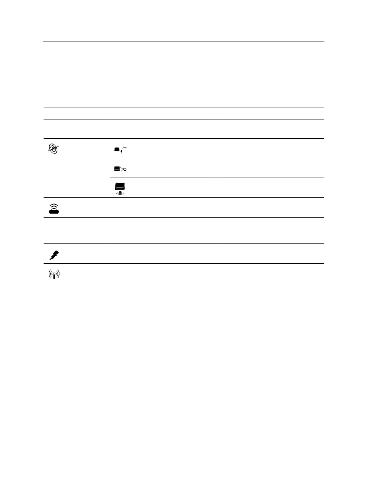
Locate - 26 Gen-Eye™ Hot Spot™ Operator’s Manual
Prepare
Prepare
Select Signal Mode
Gen-Eye Hot Spot receivers detect active and passive signals. Select the signal best suited for the locating
jobsite. Depending on the receiver model, all modes might not be available.
Signal Mode/Type Description Notes
Signal placed on a target line with a
Active Signals:
Line signal Direct Connection (preferred method) requires a
transmitter
connection directly to the target line
Clamp Induction requires placing an optional induction
clamp around the target line
Broadcast induction sends current into lines near the
transmitter
Beacon signal Signal transmitted from a beacon
inside a pipe or conduit
Passive Signals: Signal that a utility line picks up from
the environment
Power Signal Allows receiver to trace live 50 Hz or
60 Hz power cables
Radio Signal Allows receiver to trace cables that
pick up and radiate very low
frequency (VLF) radio waves
IMPORTANT: Current must be flowing
through the cable.
CMW
®
Page 28
Gen-Eye™ Hot Spot™ Operator’s Manual Locate - 27
Prepare
Select Antenna Configuration
Select the antenna configuration best suited for the locating jobsite.
Antenna Description Advantage / Disadvantage
Single Peak Uses one horizontal antenna to detect signal.
Response is highest at strongest signal.
Twin Peak Uses two horizontal antenna to detect signal.
Response is highest at strongest signal.
Null point Uses a vertical antenna to detect signal.
Search width is narrower than single peak.
Response is lowest when receiver is over the
line.
Total Field Uses a combination of two horizontal and one
vertical antenna to locate signal.
more range / less precise
most precise / less range
sharp response / easily distorted
in congested areas
easy to use when sweeping and
eliminates ghost signals / easily
distorted in congested areas
Select Frequency
The Gen-Eye Hot Spot transmitter can send signals in 4 frequencies at 5 watt power levels. Likewise, the
receiver can display information in over 70 frequencies. Optimal frequencies for your area can be
configured for each unit using software. Then, use the transmitter and receiver frequency menus to
activate only the frequencies most suited for a particular jobsite. Be aware of these points:
• Lower frequencies travel farther than higher frequencies.
• Higher frequencies couple onto lines more easily.
• Higher frequencies also couple onto lines other than the target line more easily.
CMW
®
Page 29
Locate - 28 Gen-Eye™ Hot Spot™ Operator’s Manual
Prepare
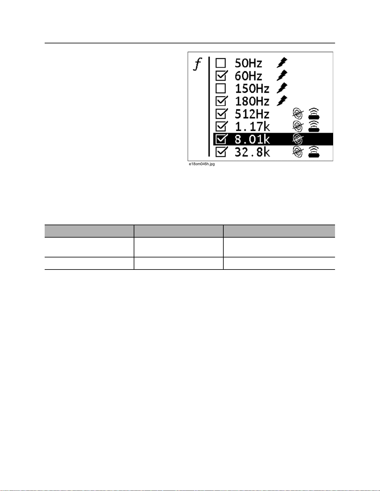
Activate Frequencies
To activate frequencies on the transmitter as well
as the receiver:
1. Navigate to Settings>Frequency menu.
2. Select the frequencies best suited for the
jobsite conditions. When the box is checked,
the frequency is active.
Note: Power, line, and beacon icons indicate
which mode a frequency is suited for.
3. While locating, press the Frequency button
to toggle between activated frequencies.
Adjust Receiver Gain
The receiver gain setting controls the sensitivity to the signal.
Action Result Effect
increasing gain more sensitive to signal allows location farther away from
signal source
decreasing gain less sensitive to signal stabilizes signal
CMW
®
Page 30
Gen-Eye™ Hot Spot™ Operator’s Manual Locate - 29
Locate Active Signals
Locate Active Signals
Setup
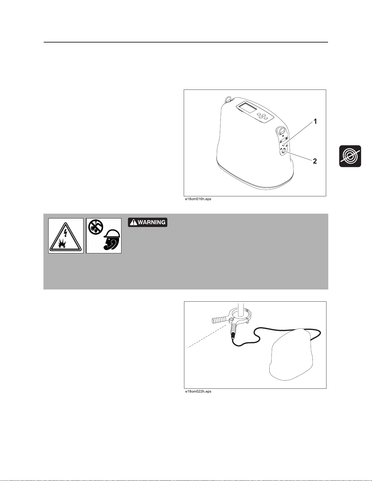
Follow setup procedures for the type of locating
you will be doing: direct connection, induction
clamp, or broadcast. For all types of active
location that require leads, connect leads to
transmitter at connector (2). Keep connector
covered when not in use. When it is necessary to
connect to external power, use connector (1).
Induction Clamp
Jobsite hazards could cause death or serious injury. Use
correct equipment and work methods. Use and maintain proper safety
equipment.
NOTICE: Electric shock or equipment damage can result if transmitter is connected to live cable.
Contact qualified utility personnel and follow all standards and requirements for disconnecting and
grounding cables.
To set up transmitter for use with induction
clamp:
1. Plug cable into transmitter.
2. Place clamp around cable.
3. Turn on transmitter.
4. Check battery level.
CMW
®
Page 31
Locate - 30 Gen-Eye™ Hot Spot™ Operator’s Manual
Locate Active Signals
Direct Connection
Jobsite hazards could cause death or serious injury. Use
correct equipment and work methods. Use and maintain proper safety
equipment.
NOTICE:
• Electric shock or equipment damage can result if transmitter is connected to live cable. Contact
qualified utility personnel and follow all standards and requirements for disconnecting and grounding
cables.
• A built-in circuit breaker will automatically disable transmitter when leads are connected to a live
cable. Display will flash and transmitter will beep. Turn off transmitter and disconnect from cable to
reset breaker.
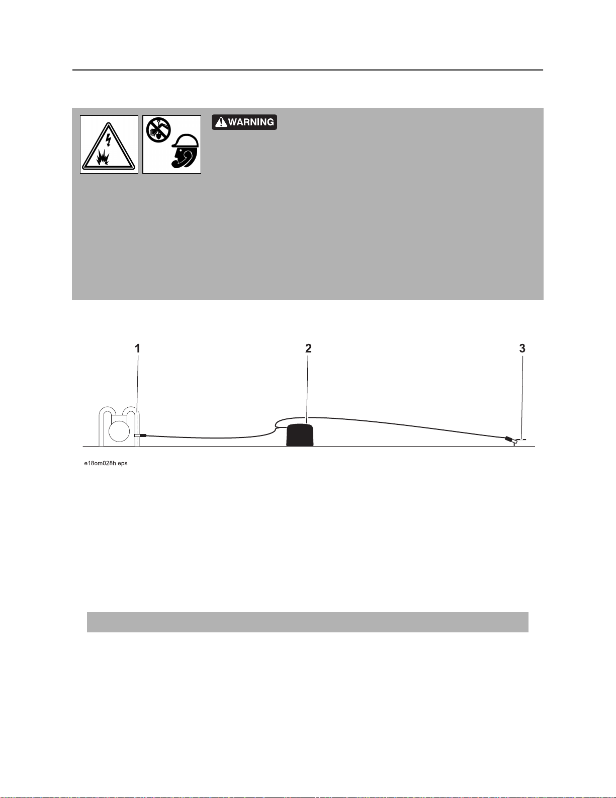
To set up transmitter for direct connection:
1. Carefully push ground stake (3) into ground.
2. Plug cable into transmitter (2).
3. Connect black lead to ground stake.
4. Connect red lead to cable (1).
Note: If using dual location, connect white lead to the additional cable to be located.
5. Turn on transmitter and check battery level.
NOTICE: Turn off transmitter when connecting or moving ground stake.
®
CMW
Page 32
Gen-Eye™ Hot Spot™ Operator’s Manual Locate - 31
Locate Active Signals
Induction
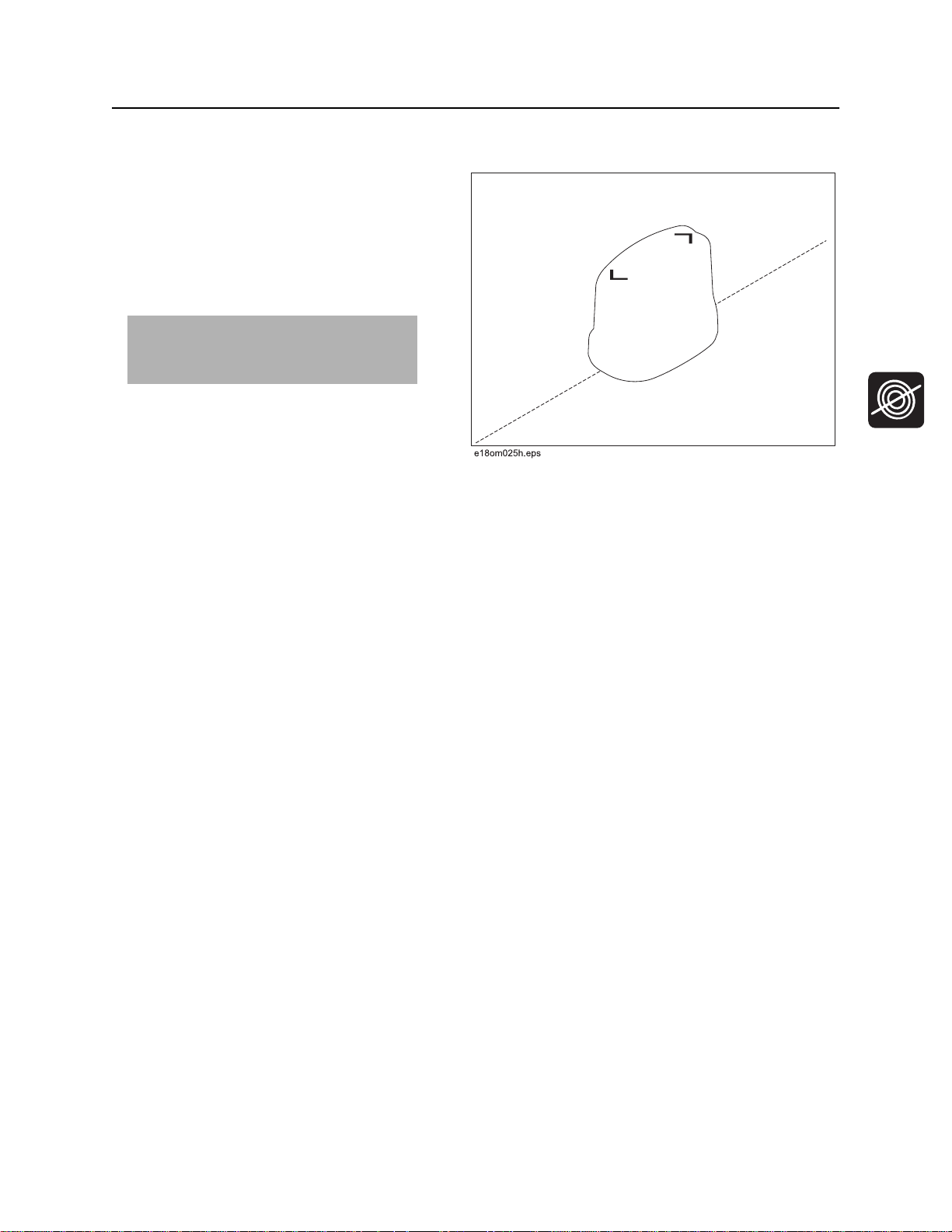
To set up transmitter for induction:
1. Remove cable, stake, clamp and any other
metal objects from transmitter.
2. Place transmitter parallel to and directly
above suspected cable as shown.
Note: Transmitter must be parallel to
object, as shown, in order to produce
the best signal.
3. Turn on transmitter.
4. Check battery level.
CMW
®
Page 33
Locate - 32 Gen-Eye™ Hot Spot™ Operator’s Manual
Locate Active Signals
Technique
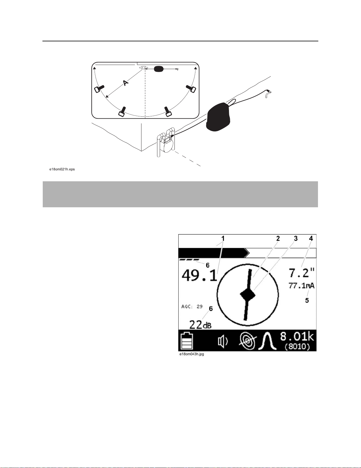
IMPORTANT: Follow steps below for all types of active location. For reference, the illustration above
shows direct connection method. If using broadcast induction, ensure that transmitter is in line with and
above suspected cable, as shown on previous page.
1. Facing away from the transmitter, walk in an arc approximately 25’ (A, 7.5 m) around transmitter, as
shown above.
2. Rotate the receiver and observe the screen:
• Target is located where signal response
(1) is strongest. Signal strength is shown
graphically as well as numerically.
• Adjust gain as needed to maintain signal
strength. Gain is shown graphically as
well as numerically (6).
• The Compass Line (2) shows the direction
the cable runs.
• Move in the direction of the center arrows.
When the arrows form a diamond (3), the
target is located.
• AutoDepth reading (4) will appear when
target is correctly located. If operating in
Manual depth mode, press and hold the
Depth button.
• Use Current Measurement (5) to identify target cable. Current on the target cable should be higher
than current on another cable that is picking up signal inductively from target cable.
3. Continue to trace the cable and observe depth estimates every few paces.
4. Retrace the cable and mark with appropriate flags or paint.
®
CMW
Page 34
Gen-Eye™ Hot Spot™ Operator’s Manual Locate - 33
Locate Active Signals
Mark the Cable
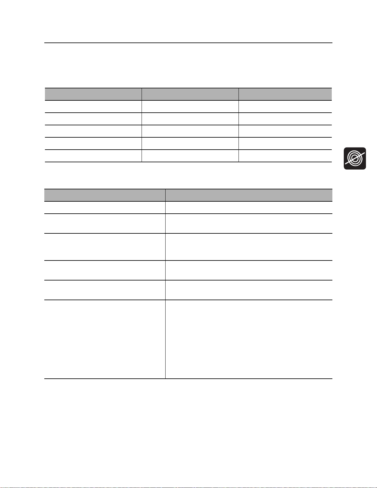
Sweep, focus, and trace all detected signals in the area. Mark cable paths with colored paint or flags. See
the chart below for standard color markings for cable locations.
Utility Color Marking Symbol
electric red -Egas/oil yellow -Gcommunications orange -TEL- or -TVwater blue -Wsewer green -S-
Special Situations
Situation What to try
Signal is lost. Walk in a circle to detect a tee or bend in the cable.
Signal varies from low to high and is
unstable.
You are near a power line and are
receiving interference.
Receiver does not function properly. Receiver gain could be set too high or low. Lower or raise
Target cable has connections to other
cables.
Signal is transferring to other cables. • Lower the frequency.
Mark as a hand-dig area.
Sweep the area in 50 Hz or 60 Hz power mode. If receiver
gives a strong signal response, a power line is interfering
with transmitter signal.
gain to locate the cable.
Disconnect target cable from other cables or use direct
connect or induction clamp to focus signal on target cable.
• Lower the power level.
• Use direct connection, if possible, or use induction
clamp.
• Move the ground stake away from the target cable and
away from other buried cables.
• Apply signal at the point where the target cable is
farthest from the other cables.
CMW
®
Page 35
Locate - 34 Gen-Eye™ Hot Spot™ Operator’s Manual
Locate Passive Signal
Locate Passive Signal
Setup
Follow setup procedures for the type of locating you will be doing. Always check receiver battery level at
startup.
NOTICE: Cables with no A/C current flowing through them are hard to detect and may be hazardous
because they may still have voltage potential. To locate, turn on an appliance to cause current to flow
and use active search methods.
Technique
Survey the Site
Make a visual check of the site for signs of buried cables such as:
• recent trenching
• buried cable markers
• overhead lines that run down pole and underground
• gas meters
• valve sights
• drains or manhole covers
Sweep the Site
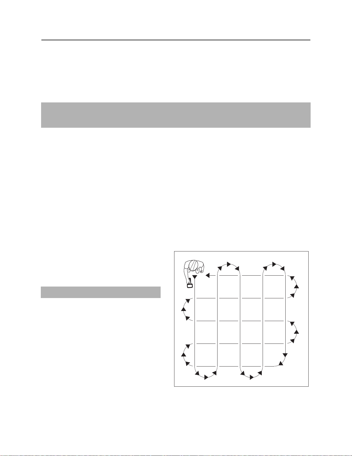
Search the site by walking a grid pattern while
holding receiver close to the ground.
NOTICE: Keep receiver vertical.
Focus the Signal
Move receiver over detected signal to find best
signal response. If using a peak antenna
mode, rotate receiver until signal is best. Best
signal indicates cable direction.
CMW
ss1076a-d.eps
®
Page 36
Gen-Eye™ Hot Spot™ Operator’s Manual Locate - 35
Locate Passive Signal
Trace the Cable
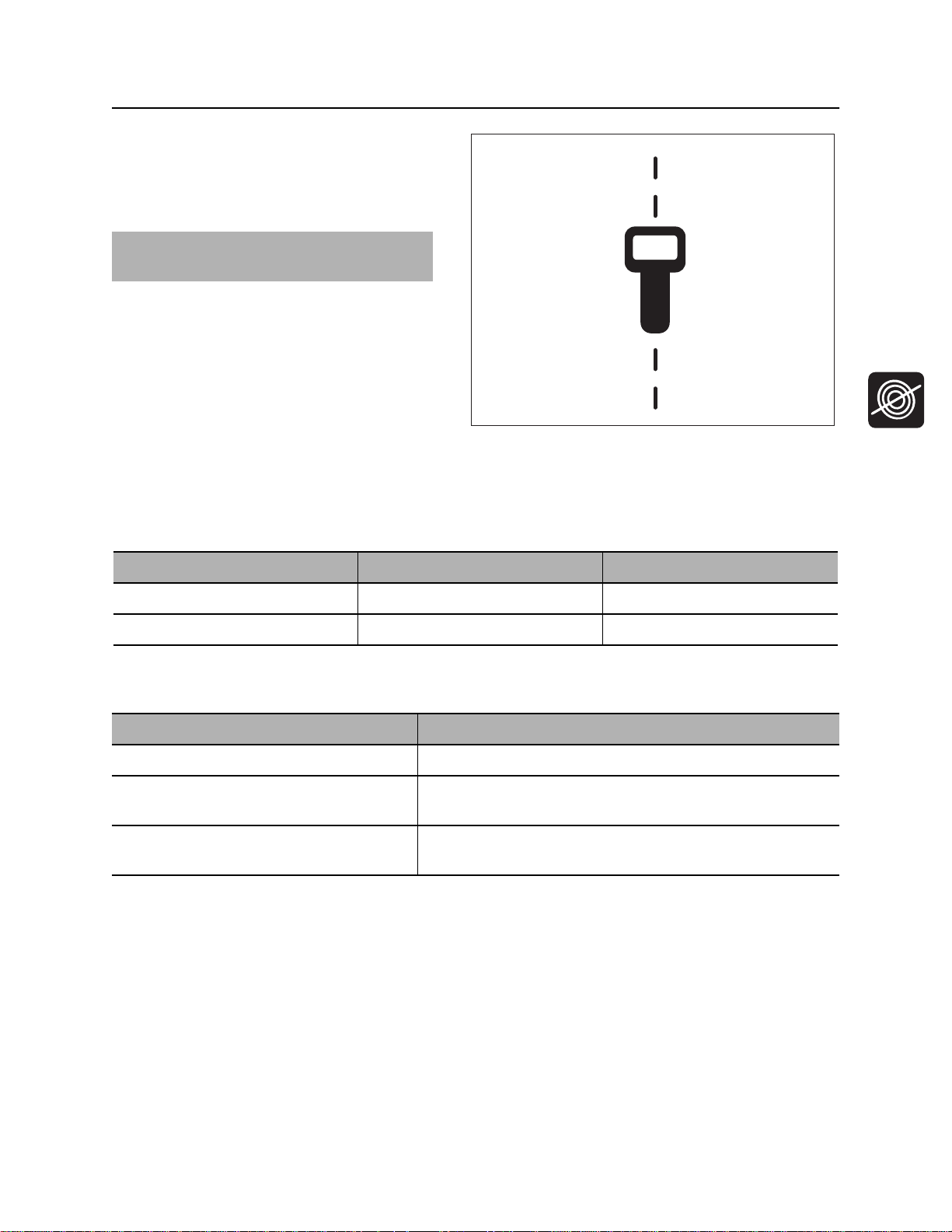
Walk along the suspected path while moving
the receiver from side to side across the area.
IMPORTANT: Keep receiver handle parallel
to the suspected cable path.
ss1080a-d.eps
Mark the Cable
Sweep, focus, and trace all detected signals in the area. Mark cable paths with colored paint or flags. See
the chart below for standard color markings for cable locations.
Utility Color Marking Symbol
electric red -Ecommunications orange -TEL- or -TV-
Special Situations
Situation What to try
Signal is lost. Walk in a circle to detect a tee or bend in the cable.
Signal varies from low to high and is
unstable.
Receiver does not function properly. Receiver gain could be set too high or low. Lower or raise
Mark as a hand-dig area.
gain to locate the cable.
CMW
®
Page 37
Locate - 36 Gen-Eye™ Hot Spot™ Operator’s Manual
Locate Beacon Signal
Locate Beacon Signal
Trace metallic pipes or conduits by locating and following a beacon signal.
IMPORTANT: Large metal objects and other signals (such as railroad signals or overhead power lines)
will distort signal.
Setup
1. Follow instructions for installing beacon battery.
2. Turn on receiver to ensure that beacon is functioning properly.
3. Attach beacon to plumber’s snake or flex rod.
Technique
1. Turn on receiver.
2. Set operating mode to Beacon location.
3. Set antenna configuration to Total Field.
4. Place beacon into the pipe and move it down
the pipe.
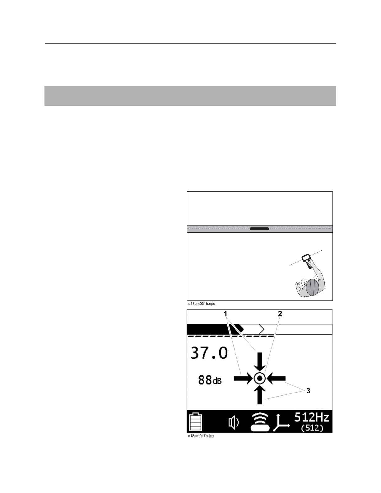
5. Locate beacon:
Null Point Method: Circle over
approximate location. Follow directional
arrows (1, 3) to locate the null point (2).
The beacon is correctly located at peak
signal between null points.
CMW
®
Page 38
Gen-Eye™ Hot Spot™ Operator’s Manual Locate - 37
Locate Beacon Signal
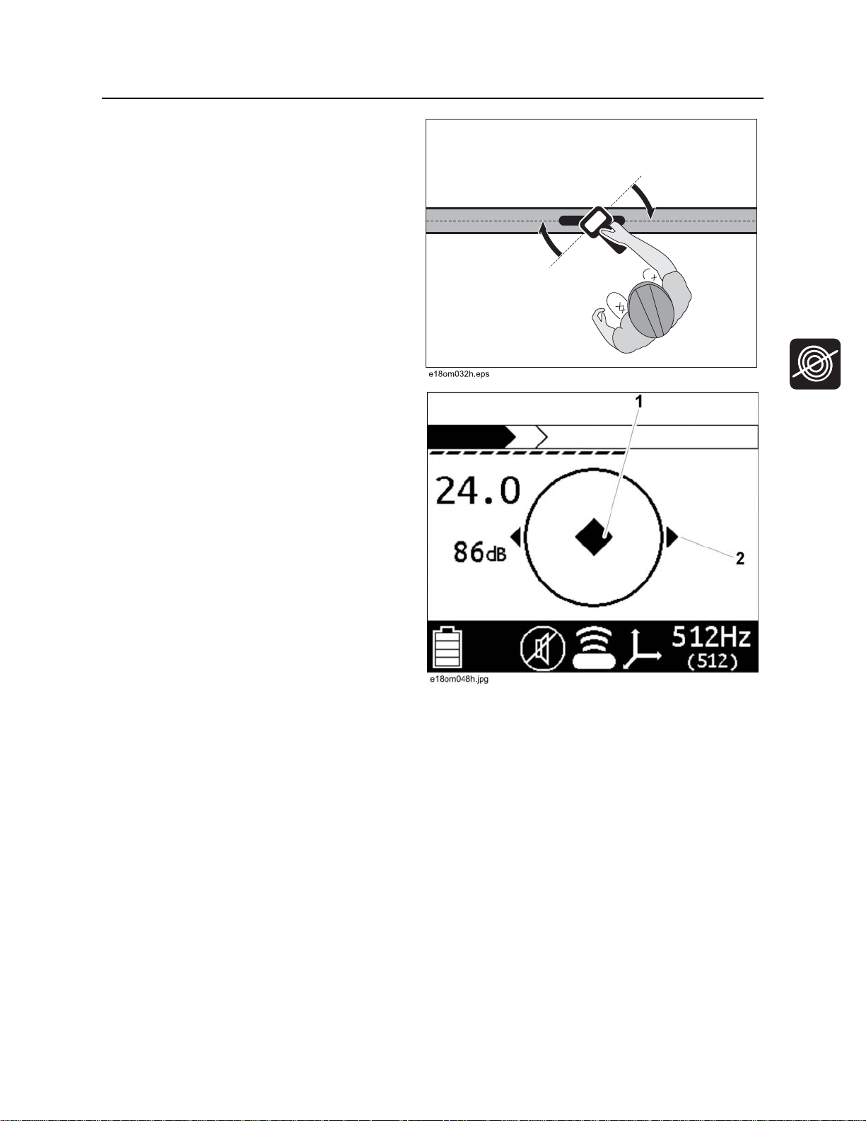
Peak Signal Method: When the peak signal
is in range, rotation arrows will appear. Follow
arrows (2) to rotate the receiver so that it is
perpendicular to the beacon.
Follow fore/aft arrow (1) to locate the
strongest signal response.
CMW
®
Page 39
Locate - 38 Gen-Eye™ Hot Spot™ Operator’s Manual
Locate Beacon Signal
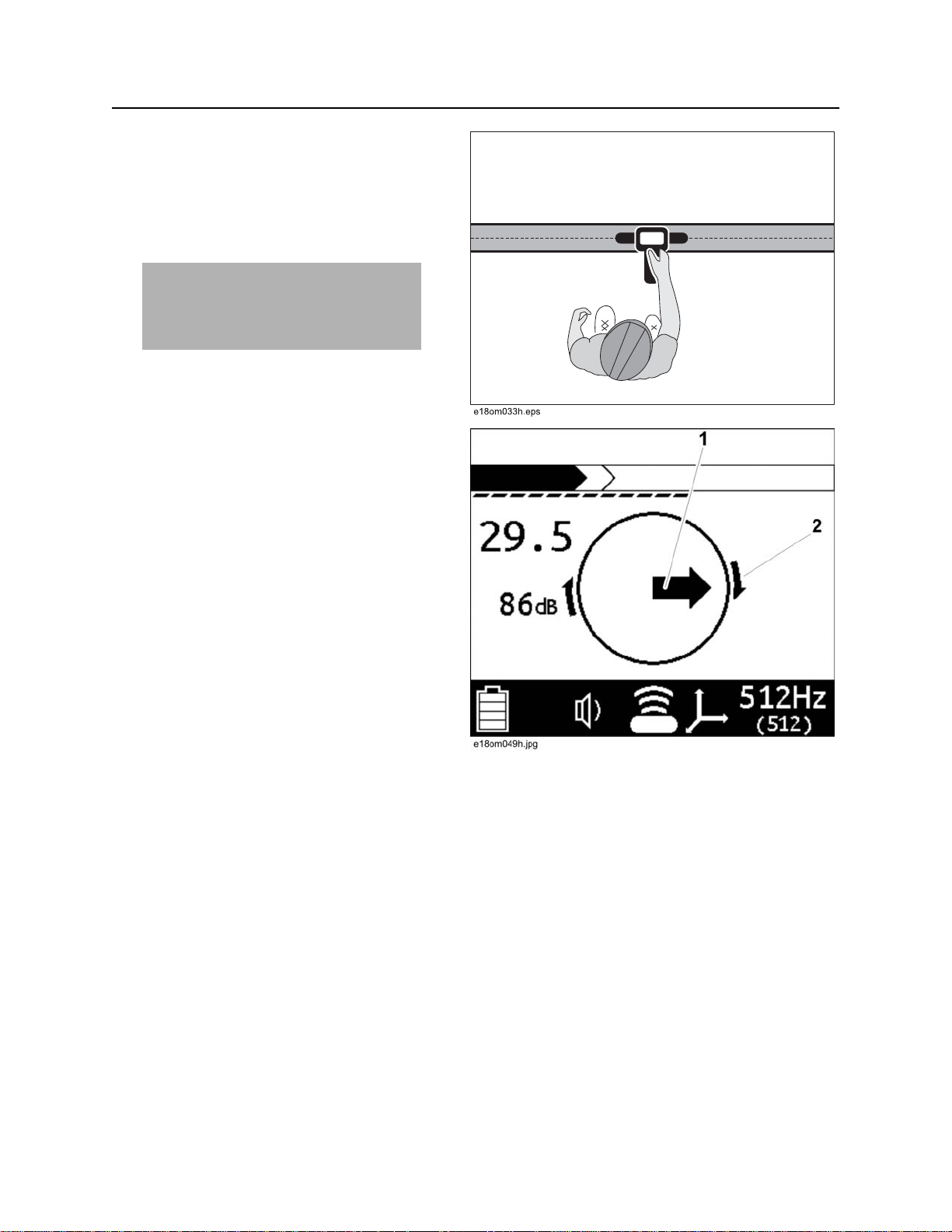
6. When the beacon is correctly located, a
diamond (1) will form in the center of the
compass, the exterior arrows (2) will appear,
and the depth reading will display.
7. If operating in Manual depth, press the Depth
key to estimate depth.
NOTICE: When estimating depth with
a beacon in nonmetallic pipe, depth
shown will be to the center of the
beacon, not to the top of the pipe.
8. Continue to track the beacon and observe
depth readings. Mark pipe location with paint.
CMW
®
Page 40
Gen-Eye™ Hot Spot™ Operator’s Manual Locate - 39
Common Signal Problems
Common Signal Problems
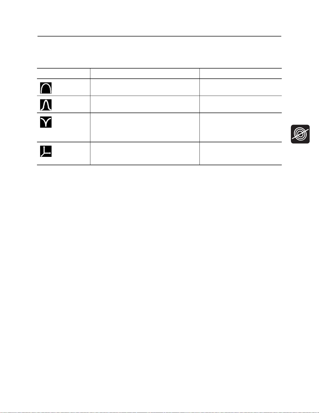
Distortions in the electromagnetic field around a cable can affect location accuracy. Tees, bends, parallel
cables, crossing cables, or large metallic objects can distort signals.
IMPORTANT: If target depth and location are critical, confirm by hand-digging or vacuum excavation.
Learn to recognize the following kinds of distortion:
Shadows
Shadows, also called blind spots, often happen when a metallic object partially obstructs the signal, or a
signal from a parallel cable interferes with target signal.
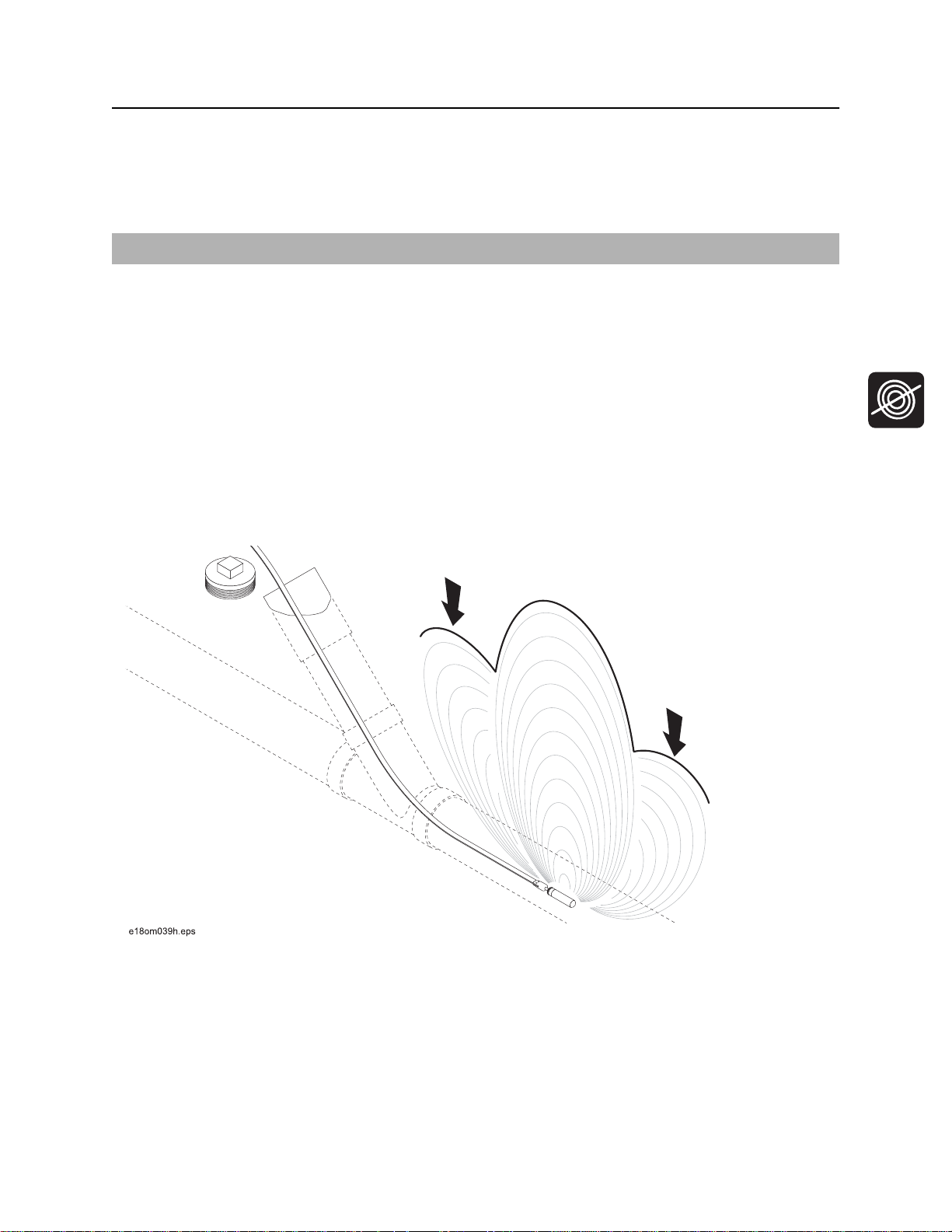
Secondary (Ghost) Signals
A typical beacon signal pattern shows a main signal and two weaker secondary signals. Identify beacon
location at the main signal. Familiarity with beacon signal patterns will lessen the effect of ghost signals.
Using the Total Field antenna mode will eliminate ghost signals. See “Select Antenna Configuration” on
page 27.
CMW
®
Page 41

Locate - 40 Gen-Eye™ Hot Spot™ Operator’s Manual
Common Signal Problems
CMW
®
Page 42

Gen-Eye™ Hot Spot™ Operator’s Manual Service - 45
Service
Chapter Contents
General Care . . . . . . . . . . . . . . . . . . . . . . . . . . . . . . 46
As Needed . . . . . . . . . . . . . . . . . . . . . . . . . . . . . . . 46
CMW
®
Page 43
Service - 46 Gen-Eye™ Hot Spot™ Operator’s Manual
General Care
General Care
Under normal operating conditions, receiver, transmitter and A-frame detector need only minor
maintenance. Following these care instructions can ensure longer equipment life:
• Do not drop the equipment.
• Do not expose the equipment to high heat (such as in the rear window of a vehicle).
• Clean equipment with a damp cloth and mild soap. Never use scouring powder.
• Do not immerse in any liquid.
• Inspect housing daily for cracks or other damage. If housing is damaged, contact your equipment
dealer for replacement.
• Do not mix new and used batteries.
As Needed
Location Task Notes
Receiver Unit Change batteries 2 “D” alkaline
Transmitter Unit Change batteries 10 “D” alkaline
Receiver Unit
Change Batteries
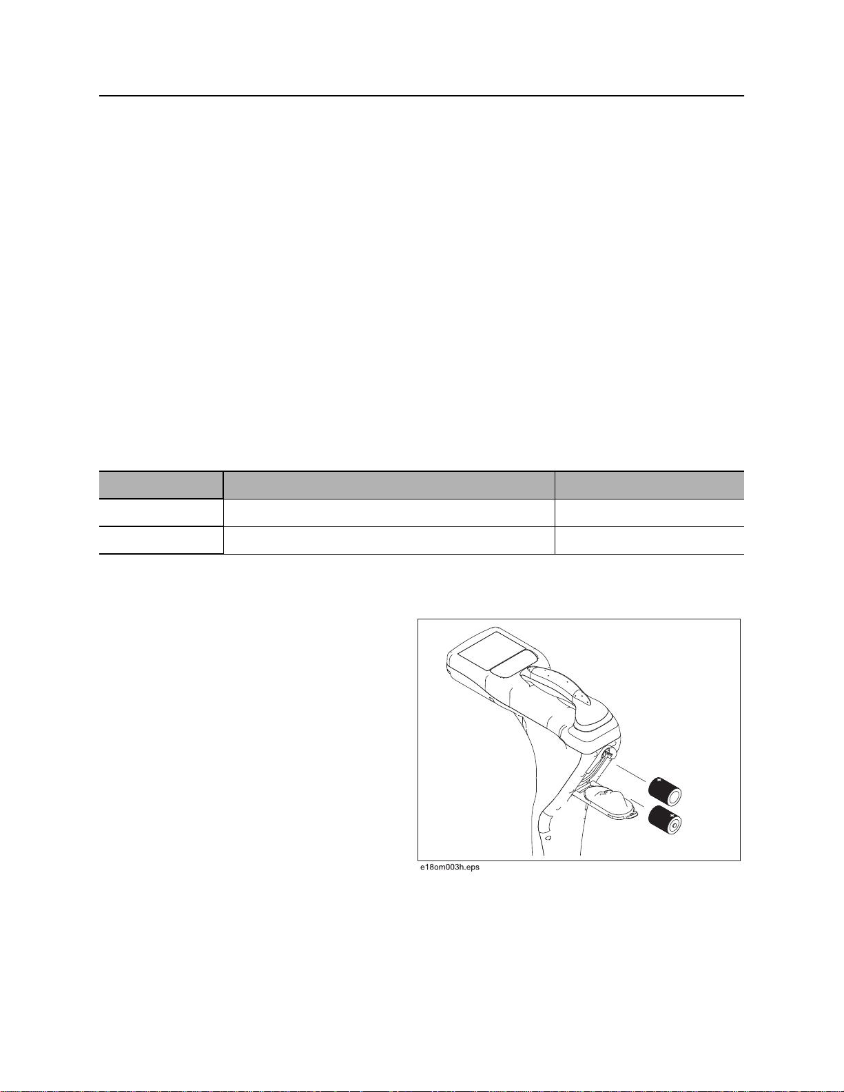
Use 2 D-cell alkaline batteries in receiver.
1. Remove battery cover.
2. Insert batteries as shown.
3. Install and tighten battery cover.
4. Check operation.
CMW
®
Page 44
Gen-Eye™ Hot Spot™ Operator’s Manual Service - 47
As Needed
Transmitter Unit
Change Batteries
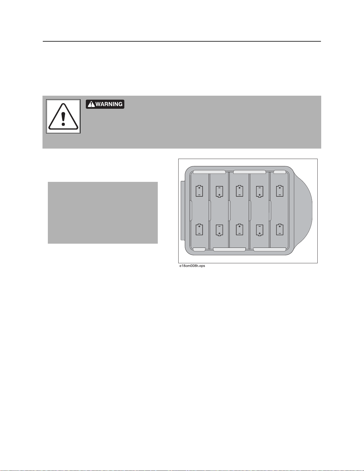
Use ten D-cell alkaline batteries or a Lithium-ion battery pack in transmitter.
Battery cells inside may vent or rupture. Do not crush, do not heat or
incinerate, do not short circuit, do not dismantle, do not immerse in any liquid. Observe
charging instructions.
To help avoid injury, see battery manufacturer’s safety instructions.
1. Open battery cover.
2. Insert batteries as shown.
IMPORTANT:
• Installing batteries backwards will
cause damage to batteries and
unit.
• Ensure that door is closed tightly.
• Do not mix new and used batteries.
3. Close and tighten battery cover.
4. Check operation. If battery light is flashing
when unit is turned on, then one battery is
incorrectly installed or batteries are weak.
CMW
®
Page 45
Service - 48 Gen-Eye™ Hot Spot™ Operator’s Manual
Update Software
Update Software
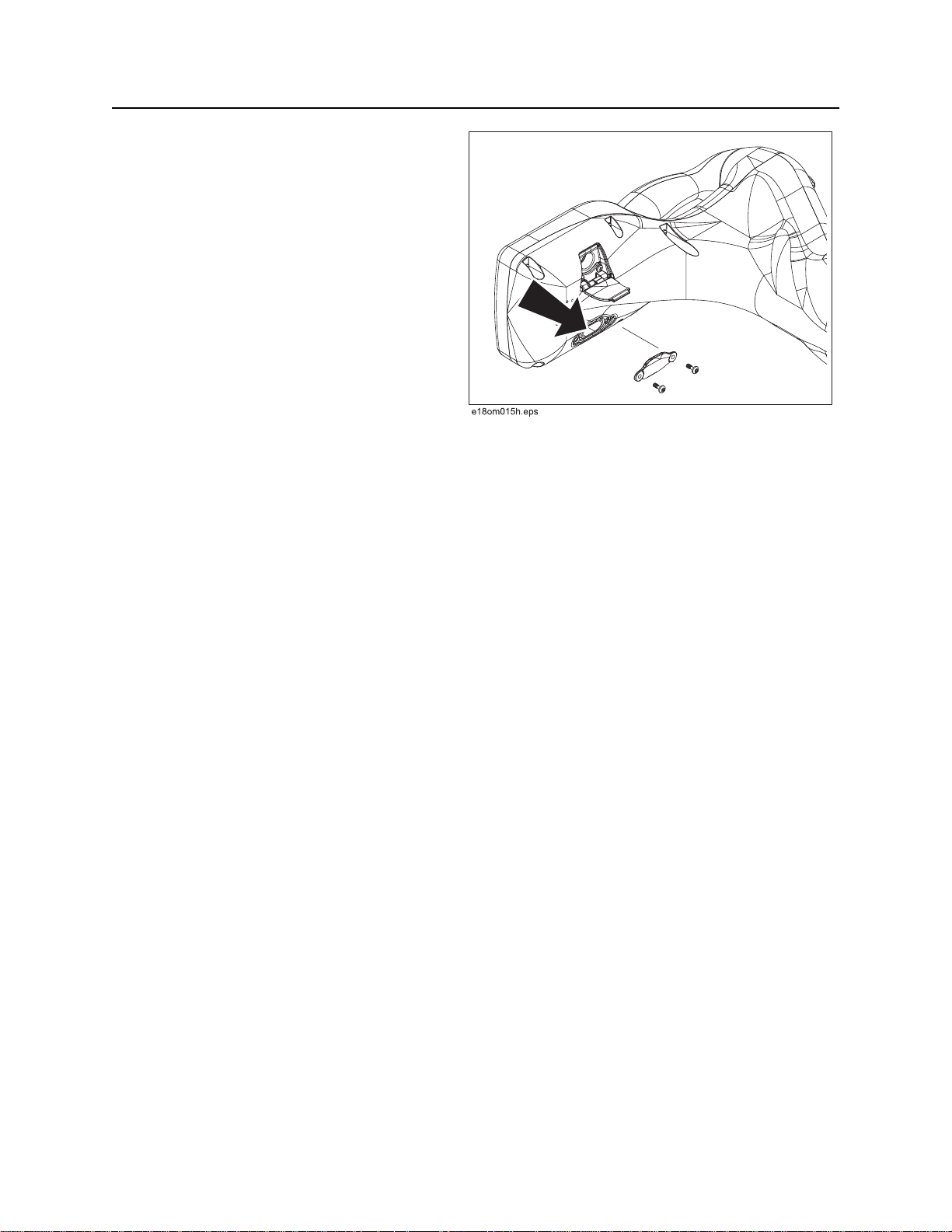
The manufacturer updates software periodically
to fix bugs and improve functionality. These
updates are accessible through web-based
software available with this product.
To install updates:
1. Use a USB cable to connect the unit to a
personal computer.
2. Launch the software and follow prompts to
install updates.
Refer to the software application for more
information.
CMW
®
Page 46
Gen-Eye™ Hot Spot™ Operator’s Manual Specifications - 49
Receivers
Specifications
Receivers
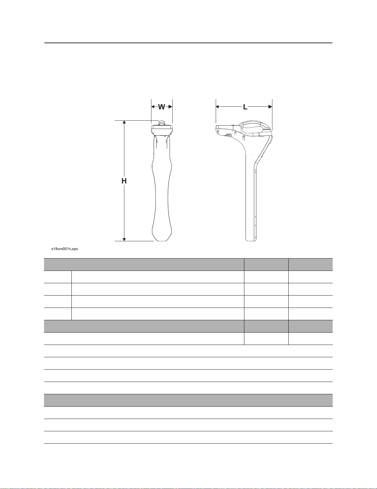
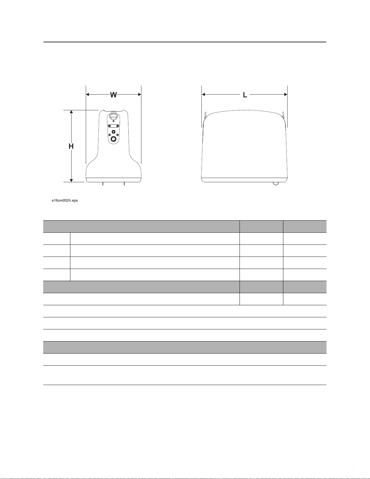
Dimensions U.S. Metric
H Height 27.2” 69.09 cm
L Length 12.8 ” 32.50 cm
W Width 4.8” 12.19 cm
Weight 4.8 lb 2.18 kg
Operation U.S. Metric
Operating temperature range -4°F to 122°F -20°C to 50°C
Antenna configurations: single peak, twin peak, null, left/right (cable only)
Audio output: speaker
LCD backlight: LED
External ports: Mini USB
Batteries
Type: 2 D-cell alkaline
Life (intermittent use at 70°F/21°C): approximately 30 hours
Battery saver: unit shuts off after 5 minutes of inactivity
CMW
®
Page 47
Specifications - 50 Gen-Eye™ Hot Spot™ Operator’s Manual
Transmitters
Transmitters
Dimensions U.S. Metric
H Height 10” 25.40 cm
L Length 12” 30.48 cm
W Width 7.8” 19.1 cm
Weight 7.8 lb 3.54 kg
Operation U.S. Metric
Operating temperature range -4°F to 122°F -20°C to 50°C
Maximum power output: 5 watts
Standard operating frequency: 1 kHz, 8 kHz, 33 kHz, 65 kHz
Timer: unit runs continuously or shuts off after running for a selected hour interval (8-hour maximum).
Batteries
Type: 10 D-cell alkaline or 1 Lithium ion battery pack (p/n 220-2221)
Life (continuous use at power level 2): Alkaline - approximately 100 hours; Lithium ion approximately 80
hours.
CMW
®
Page 48
Gen-Eye™ Hot Spot™ Operator’s Manual Specifications - 51
System Operation
System Operation
Operating Modes and Frequencies
Active cable, standard: 6 active frequencies
Passive cable, standard: 60 Hz, 120 Hz, 180 Hz, 50 Hz, 100 Hz, 150 Hz
Beacon (locate/depth only): 512 kHz and 33 kHz
Locating Ranges U.S. Metric
Cables 15’ 4.6 m
Beacons 10’ 3 m
Depth Estimate Tolerances* U.S. Metric
Passive cable ±10% 0.5-10’ 0.15-3 m
Active cable ±5% 0.2-10’ 0.2-3 m
Beacon ±5% 0.5-10’ 0.15-3 m
* Locators are calibrated to these tolerances under ideal test field conditions. Actual operating field
conditions may have signal distortions or may contain noise sources which result in depth range that is
less than specified.
CMW
®
Page 49

Specifications - 52 Gen-Eye™ Hot Spot™ Operator’s Manual
System Operation
CMW
®
Page 50

Gen-Eye™ Hot Spot™ Series Operator’s Manual Support - 53
Procedure
Support
Procedure
Notify your dealer immediately of any malfunction or failure of Gen-Eye equipment.
Always give model, serial number, and approximate date of your equipment purchase. This information
should be recorded and placed on file by the owner at the time of purchase.
Return damaged unit to dealer for inspection and warranty consideration if in warranty time frame.
All repairs must be done by an authorized repair facility. Repairs done elsewhere will void warranty.
Resources
Publications
Contact your Gen-Eye Hot Spot dealer for publications and videos covering safety, operation, service, and
repair of your equipment.
Training
For information about on-site, individualized training, contact your Gen-Eye Hot Spot dealer.
CMW
®
Page 51

Warranty - 54 Gen-Eye™ Hot Spot™ Series Operator’s Manual
Electronics Limited Warranty Policy
Warranty
Electronics Limited Warranty Policy
Subject to the limitation and exclusions herein, free replacement parts and labor will be provided when a
unit fails due to a defect in material or workmanship within one (1) year of first commercial use (See
Exceptions below for specific products). Defects shall be determined through inspection by Manufacturer
or authorized repair centers. An inspection must occur within thirty (30) days of the date of failure of the
product or part by Manufacturer or its authorized repair facility. Manufacturer will provide the location of its
inspection facilities or its nearest authorized dealer upon inquiry. Manufacturer reserves the right to supply
remanufactured replacement parts under this warranty as it deems appropriate. Each warranty repair
carries the remainder of the factory warranty or 90 days, whichever is longer, for all repaired components
and labor.
Product Warranty Exceptions:
• All Locate Beacons and Accessories carry a six (6) month warranty.
• All Used (Cosmetic) Electronics products sold from Manufacturer carry a six (6) month warranty from
date of sale to dealer.
EXCLUSIONS FROM PRODUCT WARRANTY
• All defects or damages caused by misuse, abuse, improper installation, alteration, neglect,
modification, lack of maintenance, or uses other than those for which products were intended.
• All defects, damages, or injuries caused by improper training, operation, or servicing of products in a
manner inconsistent with manufacturer’s recommendations.
• All batteries, which are considered consumable and therefore not covered under this warranty.
• All damaged plastics are considered to be the result of misuse or neglect unless Manufacturer has
determined otherwise.
• All repairs or attempted repairs by non-certified repair facilities or personnel will void the warranty.
• All incoming duties and freight charges.
CMW
®
Page 52

Gen-Eye™ Hot Spot™ Series Operator’s Manual Warranty - 55
Electronics Limited Warranty Policy
(Exclusions from Product Warranty, continued)
• Manufacturer reserves the right to make changes in design and/or improvements to products from time
to time, and user understands that Manufacturer shall have no obligation to upgrade any previously
manufactured product to include any such changes.
• In no event shall Manufacturer or its agents, assigns or parent company be liable for any indirect,
special, incidental, or consequential damages or for any cover, loss of information, profit, revenue or
use based upon any claim by user for breach of warranty, breach of contract, negligence, strict liability
or any other legal theory. In no event shall Manufacturer liability exceed the amount user has paid for
the Manufacturer product.
• Manufacturer will not be responsible for loss of accessories or loss or erasure of data storage media.
• Should it be determined that applicable law prohibits enforcement of any provision of this Warranty
Policy, then to the extent it is necessary to comply with the applicable law, this Warranty Policy shall be
deemed amended.
• This Warranty Policy shall be the entire agreement between Manufacturer and the Purchaser. Any
statements that purport to be different than or modify or expand the terms set forth in this written policy
are not effective for any purpose. ANY IMPLIED WARRANTIES, INCLUDING WARRATIES OF
MERCHANTABILITY AND FITNESS FOR A PARTICULAR USE ARE EXPRESSLY DISCLAIMED. IN
NO EVENT SHALL GENERAL PIPE CLEANERS, THE CHARLES MACHINE WORKS, INC., OR ANY
AUTHORIZED SERVICING AUTHORITY BE RESPONSIBLE FOR ANY LOSSES, INCLUDING
CONSEQUENTIAL AND INCIDENTAL DAMAGES, EXCEPT AS EXPRESSLY PROVIDED HEREIN.
SERVICE AND REPAIR
All units repaired at Manufacturer’s location or an authorized service center will carry a 90 day warranty on
all replaced components/parts and labor commencing on the date of repair.
EXTENDED WARRANTY
Consult your local Gen-Eye Hot Spot dealer for extended warranty options.
WARRANTY DETAILS
For information regarding this limited warranty, contact General Pipe Cleaners, 1101 Thompson Avenue,
McKees Rocks, PA 15136 USA, 800-245-6200, 412-771-6300, or your local dealer.
March 2013
CMW
®
Page 53

Warranty - 56 Gen-Eye™ Hot Spot™ Series Operator’s Manual
Electronics Limited Warranty Policy
CMW
®
 Loading...