


Course 13041.20D
Rear Wheel Steering
™
(QUADRASTEER
Service Technical College
)
Participant Guide Revised: 10/16/06

Caution
In order to reduce the risk of personal injury or property damage, carefully
observe the following information:
The service manuals of General Motors Corporation are intended for use
by professional, qualified technicians. Attempting service procedures
without the appropriate training, tools, and equipment could cause
personal injury, vehicle damage, or improper vehicle operation. Proper
vehicle service is important to the safety of the service technician and to
the safe, reliable operation of all motor vehicles. If a replacement part is
needed, use the same part number or an equivalent part. Do not use a
replacement part of lesser quality.
The service manuals contain effective methods for performing service
procedures. Some of the procedures require the use of tools that are
designed for specific purposes.
Accordingly, any person who intends to use a replacement part, a service
procedure, or a tool that is not recommended by General Motors, must
first establish that there is no jeopardy to personal safety or the safe
operation of the vehicle.
The service manuals contain Cautions and Notices that must be
observed carefully in order to reduce the risk of personal injury. Improper
service may cause vehicle damage or render the vehicle unsafe. The
Cautions and Notices are not all-inclusive. General Motors can not
possibly warn of all the potentially hazardous consequences that may
result by not following the proper service procedures.
The service manuals cover service procedures for vehicles that are
equipped with Supplemental Inflatable Restraints (SIR). Failure to observe
all SIR Cautions and Notices could cause air bag deployment, personal
injury, or otherwise unneeded SIR repairs. Refer to the SIR component
and wiring location views in Restraints before performing a service on or
around SIR components or wiring.
If multiple vehicle systems are in need of repair, including SIR, repair the
SIR system first to reduce the risk of accidental air bag deployment and
personal injury.
January 2002
© 2006 General Motors Corporation
All Rights Reserved

Table of Contents
Welcome and System Instructions .......................................................................i
Introduction ....................................................................................................... i-1
Module 1: Rear Wheel Steering System Introduction .....................................1-1
Module 2: Rear Wheel Steering System Operation ........................................2-1
Module 3: Four Wheel Steering Alignment......................................................3-1
Appendix..........................................................................................................A-1
Evaluation.........................................................................................................E-1
Instructor:
This manual contains information about service for the Rear Wheel Steering System. Always refer to applicable vehicle service information
and appropriate Dealer Technical Service Bulletins for additional information regarding system operation and diagnostic/repair procedures.
When this manual refers to a brand name, a number, or a specific tool, you may use an equivalent product in place of the recommended
item.
All information, illustrations and specifications in this manual are based on the latest product information available at the time of publication
approval. General Motors reserves the right to make changes at any time without notice.
No part of this book may be reproduced, stored in any retrieval system, or transmitted in any form or by any means (including but not
limited to electronic, mechanical, photocopying, and recording) without prior written permission of General Motors Corporation. This applies to
all text, illustrations, tables and charts.
© 2001, 2002, 2003, 2004, 2005, 2006
QUADRASTEER
TM
is a registered treademark of Delphi Automotive Systems, Inc.
© 2006 General Motors Corporation
All Rights Reserved

i Rear Wheel Steering (QUADRASTEERTM)
Welcome to Rear Wheel Steering
(QUADRASTEERTM)
Before the broadcast begins, please read the following information which will
help you understand the One Touch site controller and keypad — your links to
the instructor and the other course participants.
Using One Touch
1) Logging in to the system
To log in to the system, follow these steps:
1. Verify correct HOST number for your session by referring to the Host number
that appears in the lower, right corner of the TV screen during the broadcast.
2. Check the Host Number that appears on your OneTouch site controller,
which is the large black box located near your TV equipment. If necessary , use the
Plus (+) or Minus (-) key on the site controller's display to change the host to the
correct number, and then press the Enter Key (↵) to log onto the host.
3. Once the keypad asks for you ID, enter your student identification number.
(U.S. Social Security, Canadian EIN or Mexican IMSS or Person ID, effective
January 2005) on your OneTouch keypad, and then press the Enter Key. The
message "Validating" appears on the keypad for a few seconds. Next, your name
appears. this confirms that you have logged onto a host.
NOTE: If you have already logged in to your keypad and you determine that our site
controller is NOT set to the correct host number , you must first log off the site controller
by pressing the Esc key on the site controller's display. W ait until the sytem logs you
off, and then follow the steps above for logging back into the system.
Finally , if you are experiencing any technical difficulties and are unable to log in on both
the keypad and the site controller, please call the GM T raining Help Desk at 1-888-
748-2687 and press prompt 1.
2) Speaking to the Instructor
For best results while speaking to the instructor, follow these tips:
1. Place the keypad near the front of your desk. Put your class materials
between you and the keypad.
Speak directly into the microphone on the keyp ad. The microphone is located just
2.
below the row of five function keys. Speak in a normal tone from your standard
seated position. You will be heard by all of the other course participants and the
instructor.
© 2006 General Motors Corporation
All Rights Reserved
System Instructions ii
Using the Keypad
If you want to...
Ask a question, make a
comment, enter a
discussion, or cancel a call
to the instructor.
Signal the instructor
anonymously that you do
not understand.
Answer a multiple-choice
question.
Answer a question with a
numeric answer.
press: and this will happen...
Your WAIT light will be turned on and your
Call
Flag
A
BCDE
+
Enter
name will be added to the queue. Your
SPEAK light will come on when it is your
turn to speak. If you press the CALL key a
second time, your WAIT light will go off, and
your call will be canceled.
The percentage of students signaling the
instructor is displayed on the instructors
monitor. The instructor may adjust the
lecture accordingly.
If you are taking a multiple question quiz, the
answer is stored until you answer the last
question. On single questions the answer is
transmitted to the host site when you press
the ANSWER key.
If you are taking a multiple questions quiz
the answer is stored until you answer the
last question. On single questions,the
answer is transmitted to the host site when
you press the ENTER key.
Erase a numeric answer.
See the next quiz
questions answer set, and
any response you may
have entered for that
question.
See the previous quiz
questions answer set, and
any response you may
have entered for that
question
GM Training Help Desk 1-888-748-2687
Clear
Next
Quest
Prev
Ques
NOTE: To confirm that your response has been
received by the system, your letter or number
choice will be found in brackets in the upper
right-hand corner of the keypad display.
The answer in the window will be erased. On
single questions, you must press CLEAR
before you press ENTER.
The next questions ID and answer character
set will appear on the keypad display. If you
have already answered the question, your
answer will also display.
The previous questions ID and answer
character set will appear on the keypad
display. If you have already answered the
question, your answer will also display.
© 2006 General Motors Corporation
All Rights Reserved


Rear Wheel Steering
(QUADRASTEER
Introduction
TM
)


Introduction i-1
Welcome
Welcome to Rear Wheel Steering
(QUADRASTEERTM)
One Touch Familiarization
• Press the red call button to ask a question
• Wait for a green light before speaking
• Anticipate a momentary delay when
speaking
• Contact the Technical help desk at
1-888-748-2687, prompt 1, if necessary
Question 1
In which of the following regions is your
dealership located?
Course Goal
Upon successful completion of this course, you
will be able to identify the Rear Wheel Steering
System, associated components and apply
concepts and procedures to diagnose the
system operation.
Session Objectives
Identify the Rear Wheel Steering
System and its benefits
Identify system components and their
roles in operation
Identify unique system features
Identify diagnostic procedures
A. Atlanta
B. Chicago
C. Dallas
D. Los Angeles
E. New York
Question 2
Which of the following best
describes your experience level
at GM dealerships?
A . Greater than 10 years
B. Between 5-10 years
C. Between 2-5 years
D. Less than 2 years
Strategy Based Diagnostics
Step 1. Verify customer concern
Step 2. Make quick checks
Step 3. Follow diagnostic system checks
Step 4. Check service bulletins
Step 5. Diagnostics
Step 6. Decision on cause isolation
Step 7. Repair and verification
Special Instructions
The diagnostic charts in this courseware
are for reference only. Refer to Service
Information when servicing Rear Wheel
Steering Systems.
© 2006 General Motors Corporation Introduction
All Rights Reserved

i- 2 Rear Wheel Steering (QUADRASTEERTM)
STC T raining Courses*
Video CBT IDL Hands-On
1–Component Course
2–Component Course
3–Component Course
* Sample course component combinations
X
X
X
X
XX
*Course Components
•A 1-component course has no recommended prerequisite(s) or follow-up component
•A 2-component course has a recommended prerequisite(s) CBT or Video component
which you should complete before attending the IDL
(or)
it consists of an IDL or CBT followed by a Hands-On component which you will need to take in
order to complete the course
•A 3-component course has a recommended prerequisite(s) CBT or Video component
which should be completed before attending the IDL. You will need to take the follow-up
Hands-On component in order to complete the entire course
The dealership STS Report is credited when all components of the course are completed.
NOTICE: You’ll see your Training Record and Individual Training Plan change as each
course component is successfully completed. Just visit www.gmtraining.com and check
TMS.
To purchase authentic GM Service Training Materials,
contact the GM Training Materials Headquarters at 800-393-4831.
Participant Guide © 2006 General Motors Corporation Revised 10/16/06
All Rights Reserved

Rear Wheel Steering
(QUADRASTEER™)
Module 1
Rear Wheel Steering Introduction

Rear Wheel Steering System Introduction 1-1
Module 1 Objectives
Identify the benefits of the Rear Wheel
Steering System
Describe the three phases of
operation
Describe the three modes of operation
Identify system components and
operation
Turning Radius
Identify the cautions associated with
using in-ground hoist/jack stand
Rear Wheel Steering System
Benefits
The Rear Wheel Steering System, in
combination with the front steering system,
offers several benefits over typical non-rear
steering systems:
• Reduced turning radius
• Increased stability during high-speed
maneuvers such as passing and lane
changes
• Increased maneuverability when towing a
trailer
• Better maneuverability during low-speed
maneuvers such as parking
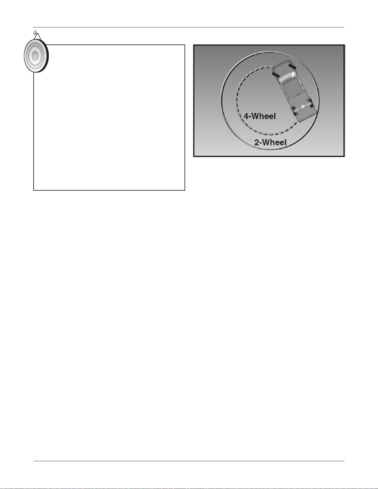
T urning Radius
The turning radius of a vehicle is significantly
enhanced with Rear Wheel Steering.
The turning radius of the GMC Sierra with
Rear Wheel Steering can be compared to
the turning radius of a Saturn Sedan
© 2006 General Motors Corporation Module 1
All rights reserved
1-2 Rear Wheel Steering (QUADRASTEER™)
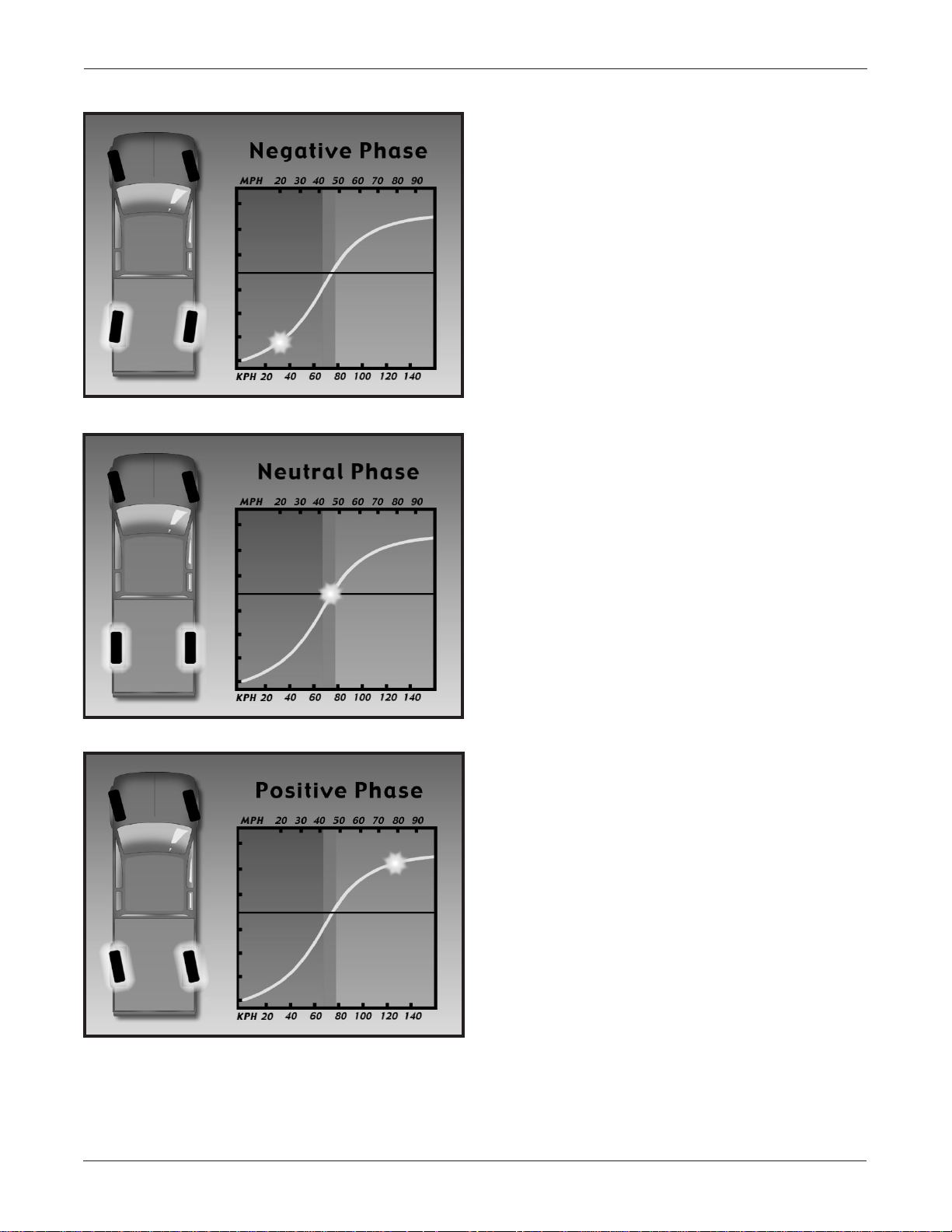
Driving Phases
Depending on the various inputs
communicated to the controller, the system
operates in one of three phases:
Negative Phase
• Used during low-speed maneuvers for
increased maneuverability
• Steers the wheels in the opposite direction
of the front wheels
Negative Phase
Neutral Phase
• Between zero and 45 mph
(approximately)
Neutral Phase
• Used during front-wheel only steering
• Rear wheels remain in a straight ahead
position no matter what direction the front
wheels turn
• It is the fail-safe phase of operation
• 45 mph (approximately)
Positive Phase
• Used during high-speed maneuvers and
when towing a trailer at high speeds for
increased stability
• Steers the rear wheels in the same
direction as the front wheels
• 45 mph and above (approximately)
The changes between the phases are subtle,
gradual changes.
Positive Phase
Participant Guide © 2006 General Motors Corporation Revised 10/16/06
All rights reserved
Rear Wheel Steering System Introduction 1-3
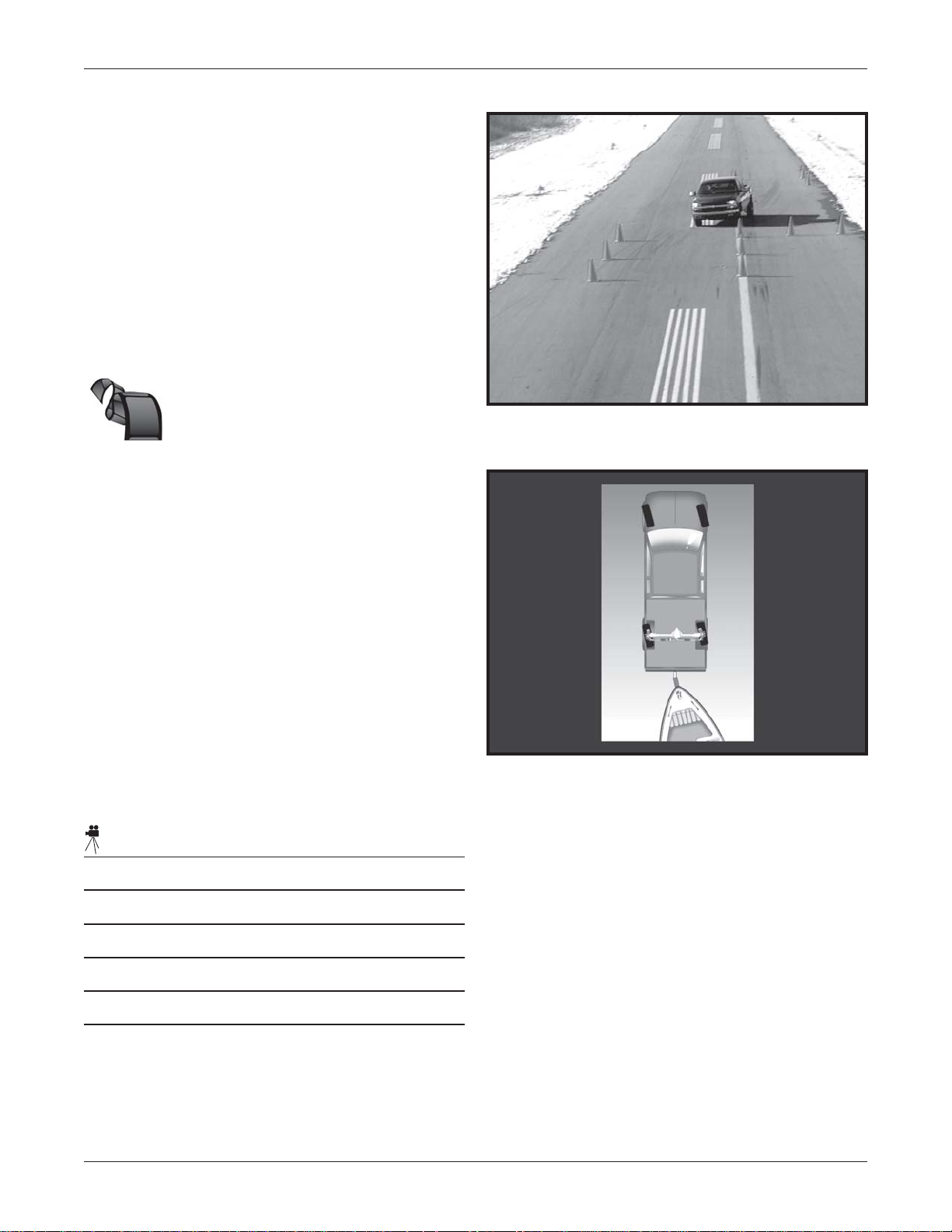
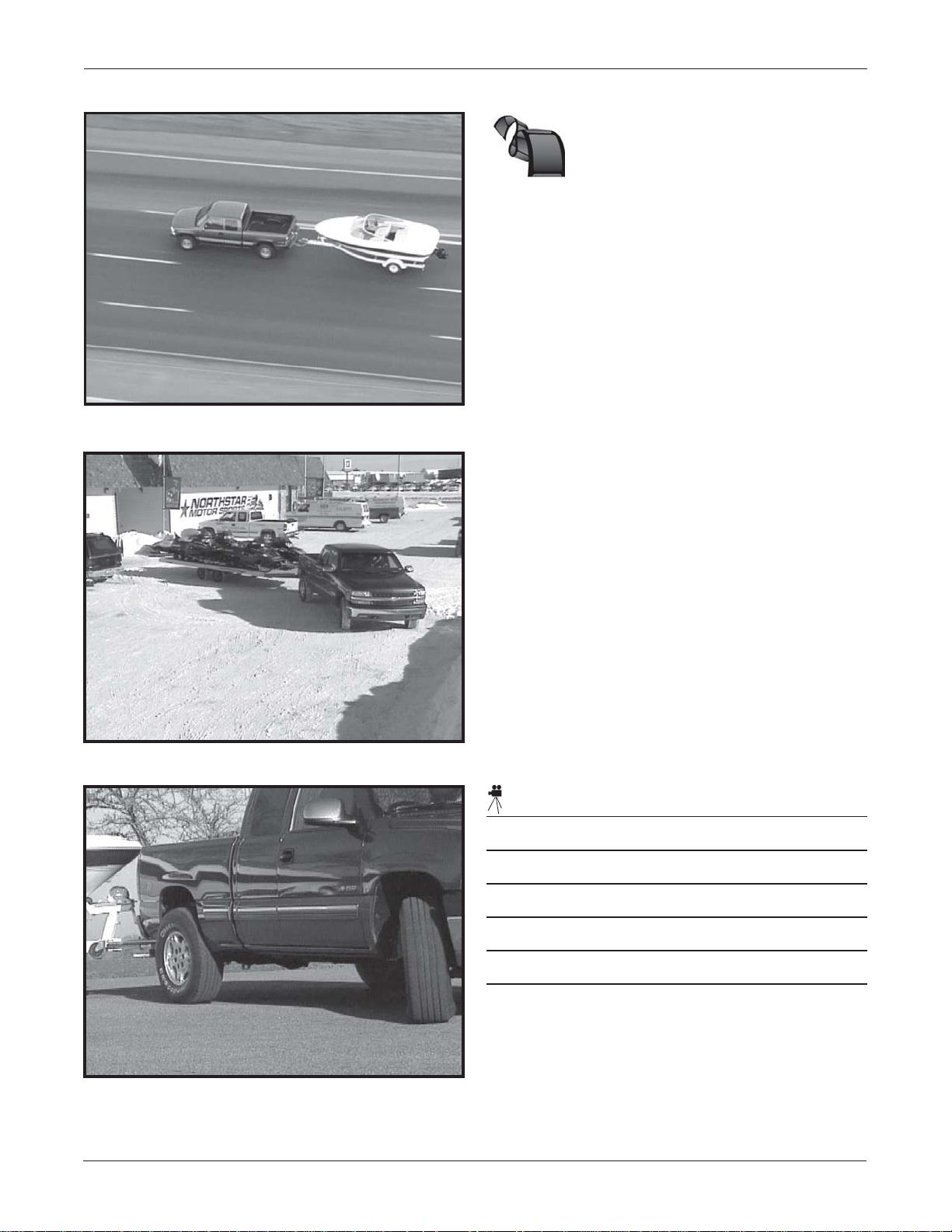
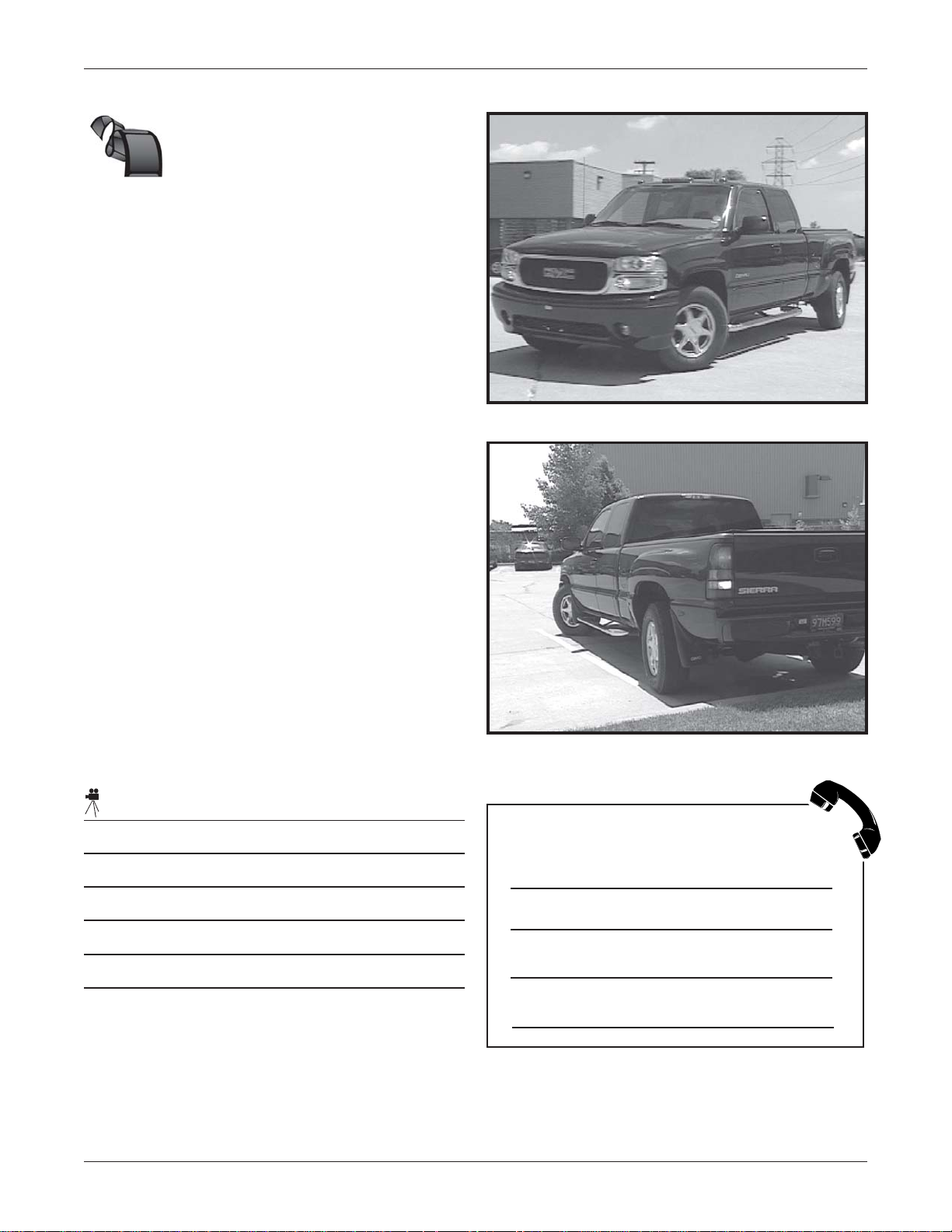
High-Speed St ability , T railering
Maneuverability , and Low-S peed
Maneuverability
These videos demonstrate how the combined
steering of the front and rear wheels improves
the truck’s maneuverability. These three video
segments will show high speed stability,
enhanced trailering and improved
maneuverability during parking.
Video Outline –
High-Speed Stability
• The Rear Wheel Steering System helps
improve stability during high-speed lane
changes
Front and Rear Wheels Turned in Same
Direction
• With the Mode Select Switch in the
4-wheel steer position, the front and rear
wheels turn in the same direction during
high-speed maneuvers
• When both the front and rear wheels turn in
the same direction, the system is operating
in the positive phase
• Positive phase Rear Wheel Steering
improves stability during higher-speed
maneuvers
Video Notes:
Lateral Motion Affected by Direction
Changes in Wheel Angle
© 2006 General Motors Corporation Module 1
All rights reserved
1-4 Rear Wheel Steering (QUADRASTEER™)
Video Outline cont. –
Trailering Maneuverability
• Stability of Rear Wheel Steering continues
with a trailer attached
• System continues operating in positive
phase, allowing the trailer to track the truck
more directly
• With Rear Wheel Steering, backing and
parking a trailer becomes easier,
particularly when additional maneuvering
Lane-Change when Towing a Trailer
space isn’t available
• When operating at slow speeds in the tow
mode, the rear wheels turn in the opposite
direction of the front wheels
Vehicle Parking with a Trailer Attached
• Allows for much easier maneuvering of the
trailer, particularly in tight spots
Video Notes:
Front Wheel and Rear Wheel Turning in
Opposite Directions
Participant Guide © 2006 General Motors Corporation Revised 10/16/06
All rights reserved
Rear Wheel Steering System Introduction 1-5
Video Outline cont. –
Low-Speed
Maneuverability
• Normal vehicle parking, especially in
tight parking spaces, also becomes
much easier with Rear Wheel Steering
• With the Mode Select Switch in the
4-wheel steer position, the front and rear
wheels turn in the opposite direction during
low-speed maneuvers, such as parking
• When the front and rear wheels turn in the
opposite direction, the system is operating
in the negative phase
• Negative phase Rear Wheel Steering
improves maneuverability while operating at
low speeds
Video Notes:
Vehicle Pulling into Parking Spot
Front and Rear Wheels Turning in Opposite
Directions
Why do we use a 5º positive phase
steering vs. a 12º negative phase?
© 2006 General Motors Corporation Module 1
All rights reserved
1-6 Rear Wheel Steering (QUADRASTEER™)
Modes of Operation
Video Outline –
The modes of operation steer by using the
driving phases.
2-Wheel Steer
• Steering Wheel Position Sensor – base of
steering column
Component Locations
– Conventional front steering
4-Wheel Steer
– Conventional front steering with rear
wheel steer
4-Wheel Steer Tow
– Conventional front steering with rear
wheel steering optimized for towing
Rear steering angle is determined based on:
• Mode selection by the driver
• Speed of the vehicle
Component Locations
The video on component locations
demonstrates the visual placement of each
component in the system.
• Mode Select Switch – instrument panel
• Yaw Rate and Lateral Accelerometer –
beneath front passenger seat (Removed in
MY04)
• Vehicle Speed Sensor – transmission
housing
• Steerable Rear Axle – normal rear axle
position
• Difference is steerable rear axle includes
quarter shafts with steering components on
ends of quarter shafts
• Rear Wheel Steering Control Module –
frame mounted on rear undercarriage of
vehicle
• Rear Actuator – positioned on rear axle and
consists of:
- Inner and outer tie rods
- Rear Position Sensor
- Steering gear motor
- Rack and pinion assembly with boots
• Wiring Harness – subsystem of the vehicle
harness
Component Locations
Participant Guide © 2006 General Motors Corporation Revised 10/16/06
All rights reserved
Rear Wheel Steering System Introduction 1-7
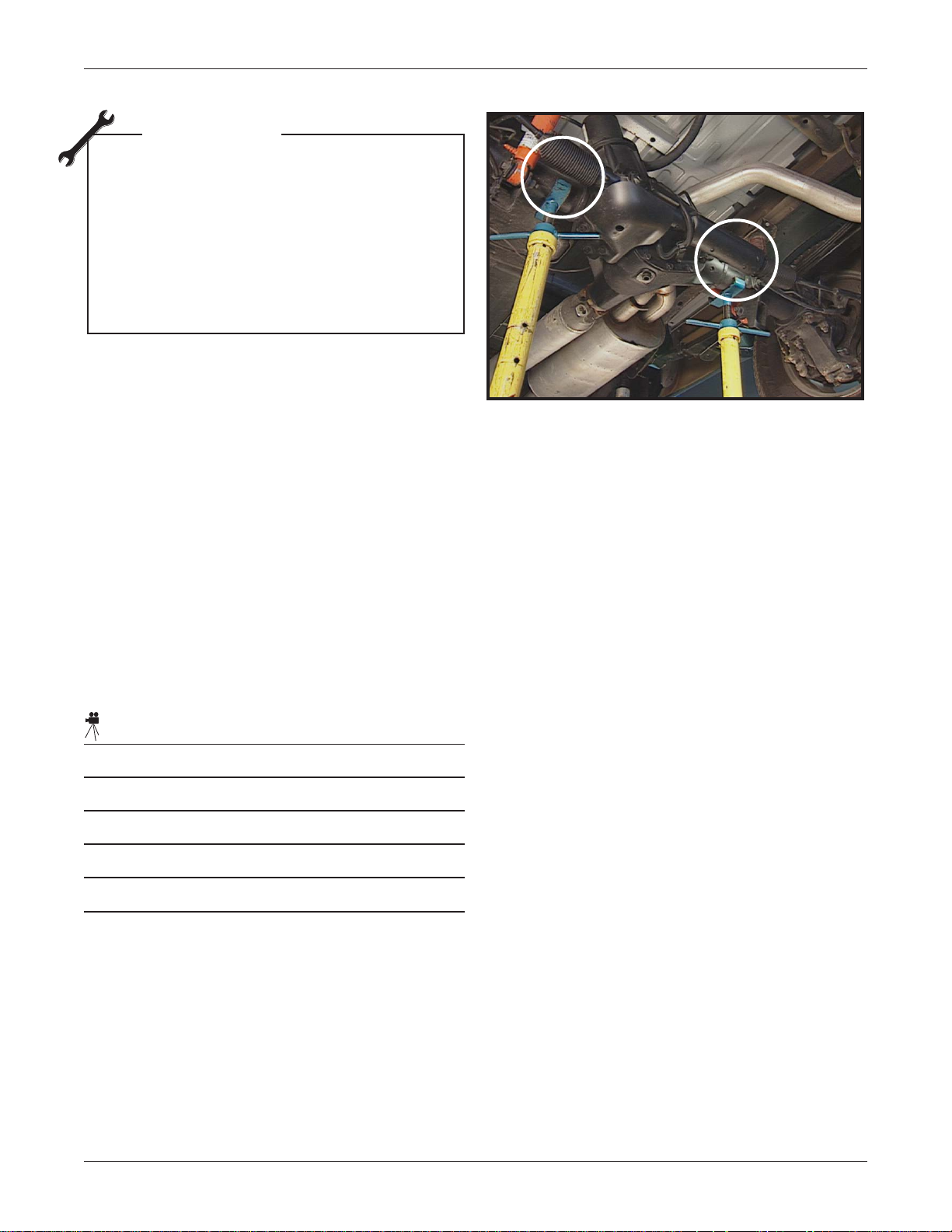
TECH TIP
Caution
When lifting the vehicle using an in-
ground hoist or supporting the axle
with jack stands, it’s very important that
the hoist is positioned at the correct
lifting points on the vehicle. If not, boot
damage may occur.
• Notice how close the lift point is to the boots
• Use caution when lifting this vehicle
Correct Lift Points (Circled)
• The recommended method to lift the vehicle
is using an above ground hoist
• Use current Service Information for details:
– Select "General Information" and then
"General Information " again. Next select
"Introduction". Finally select "Lifting and
Jacking the Vehicle".
Video Notes:
© 2006 General Motors Corporation Module 1
All rights reserved
1-8 Rear Wheel Steering (QUADRASTEER™)
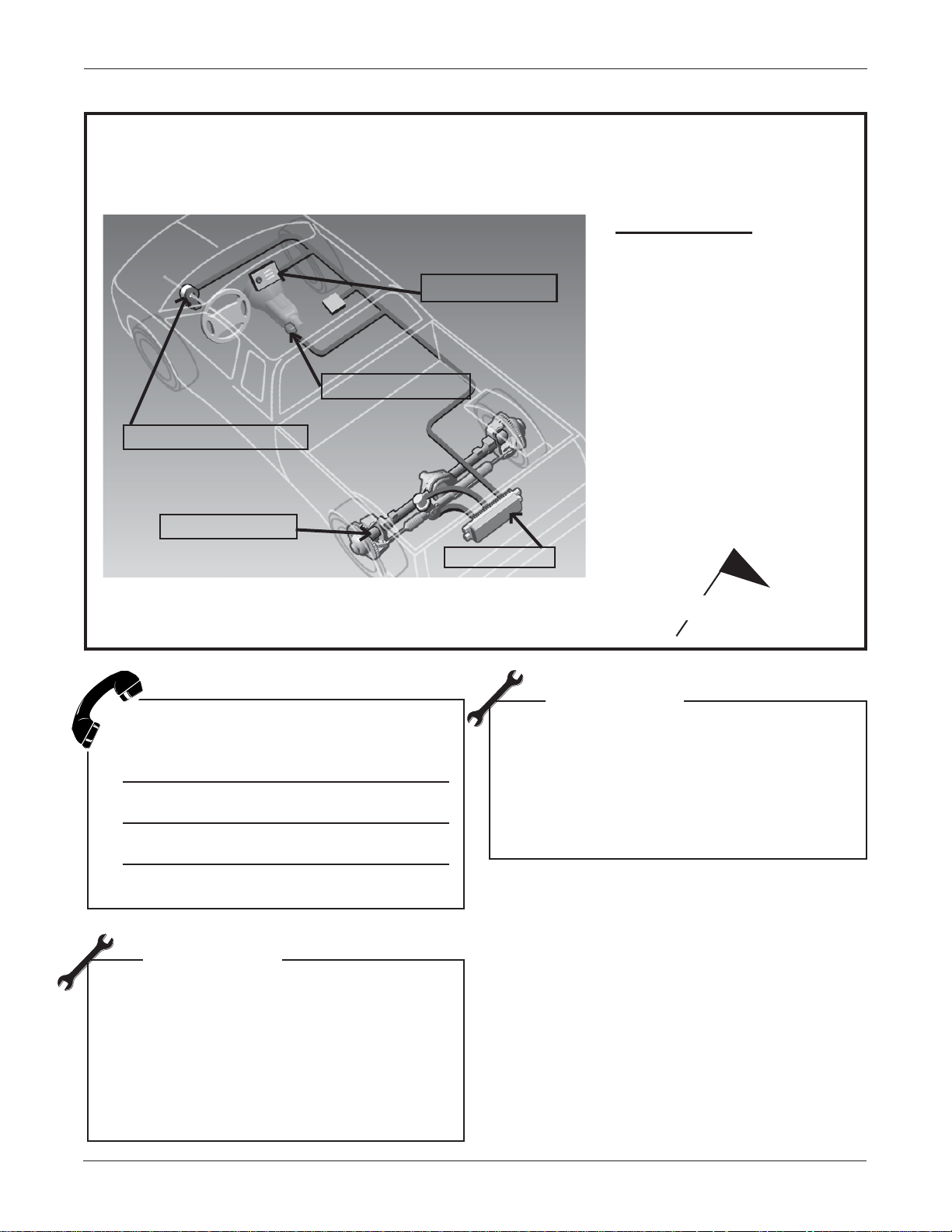
Fill in the blanks on the illustration below with the letter for each component shown in
the list.
Exercise: Component Locations
Components
A. Steering Wheel Position
Sensor
B. Vehicle Speed Sensor
C. Mode Select Switch
D. Control Module
E. Steerable Rear Axle
Identify any one of the three inputs and
its purpose.
TECH TIP
GM recommends you do not use tire
chains with the Rear Wheel Steering
System. The chains could hit the
wheel housing when the wheels are
turning left or right. If you must use
chains, keep the vehicle in 2WS mode.
Hit your flag key when finished.
TECH TIP
Do NOT change the tire size. This may
cause interference with the wheel
housing and calibration concerns
with the ABS, PCM and the Rear
Wheel Steering Module.
Module 1 Summary
Benefits of System
Three Phases of Operation
Three Modes of Operation
System Components and Operation
Caution When Using In-Ground Hoist/Jack
Stand
Participant Guide © 2006 General Motors Corporation Revised 10/16/06
All rights reserved

Rear Wheel Steering
(QUADRASTEER™)
Module 2
Rear Wheel Steering System Operation


Rear Wheel Steering System Operation 2- 1
Module 2 Objectives
Identify individual system components
and their operation
Identify unique system features
Identifiy diagnostic information as it
relates to component operation
Video Outline – Rear
Wheel Steering System
Operation
• With the Mode Select Switch in the
4-wheel steer position, the Rear Wheel
Steering Control Module identifies inputs
from:
– Steering Wheel Position Sensor
– Vehicle Speed Sensor
• Based on information from those sensors,
the control module will react either:
– in the negative phase, turning the rear
wheels in the opposite direction of the
front wheels
– in the positive phase, turning the rear
wheels in the same direction as the
front
• The amount rear wheels are steered in
either direction is based on an algorithm
programmed into the control module
Front and Rear Tires in Same Direction
Front and Rear Tires in Opposite Direction
• Algorithm takes into consideration mode of
operation selected, position of the steering
wheel and vehicle’s speed
• Control module then processes this
information and turns the rear wheels
• At a slow speed the wheels turn in the
opposite direction, or in negative phase
• At a higher speed the wheels turn in the
same direction, or in positive phase
© 2006 General Motors Corporation Module 2
All rights reserved
Algorithm Chart

2- 2 Rear Wheel Steering (QUADRASTEER™)
Steering Wheel Position Sensor
The Steering Wheel Position Sensor
determines the driver’s steering input.
• Pin can only be installed in one position due
to sensor cap alignment
• Not the same sensor used on earlier trucks
for EVO
• Similar to that used on Corvette (active
handling) or Cadillac's Stabilitrac
Steering Wheel Position Sensor
Steering Wheel Position Sensor Location
TECH TIP
The Steering Wheel Position Sensor is
pre-indexed and should NOT be rotated
after pulling the shipping pin. If the
shipping pin gets removed, or if you are
reassembling a column and reusing the
original sensor, you can center the
sensor by plugging it into the harness
and installing a scan tool. Navigate to
the rear wheel data screen and view the
steering wheel sensor analog voltage
signal. Rotate the inner portion of the
sensor to obtain 2.5 volts. This is the
centered position. The sensor can now
be mounted onto the column with the
wheels in the straight ahead position.
• Located at base of steering column
• Identifies position of the steering wheel
– Identifies direction that front wheels are
pointed
– Indicates how far the steering wheel is
turned
Steering Wheel Position Sensor
Signals (Outputs)
Unlike most two-wheel-steer trucks with this
type of sensor, the Steering Wheel Position
Sensor generates four output signals. One
signal is analog and three signals are digital.
Analog signal
– Sensor Signal
Digital signals – all high/low output
– Phase A
– Phase B
– Index Pulse
Participant Guide © 2006 General Motors Corporation Revised 10/16/06
All rights reserved

Rear Wheel Steering System Operation 2- 3
Analog signals:
• 5-volt reference
• Signal out
• Sensor return
• Reports to BCM for MY2003 and above
• Vary between near 0 or near 5 volts for all
Quadrasteer vehicles
• Indicate when steering wheel is furthest
turning capacity of either direction (+/- 225
degrees from center)
Steering Wheel Position Sensor Analog
• Indicate position of the steering wheel
• When the steering wheel is at 0
degrees,
the analog sensor voltage will be about 2.5
volts
Digital signals:
• Phase A and Phase B signals indicate the
direction and range of motion of the front
wheels
– Digital signals have a 12 volt reference
and vary from approximately 11.49 to
0.25 volts (for MY03 and newer)
Output to Control Module
5
4
3
2
1
0
0 100-100 200 300-200-300
Steering Angle (deg)
– MY02 uses a 5 volt reference circuit
• Index pulse marker signal indicates:
– When the steering wheel is in the
centered position
– When the front wheels are
positioned straight ahead
– Used for mode change
– Sensor must indicate steering wheel
has moved ±10º for change to occur
© 2006 General Motors Corporation Module 2
Steering Wheel Analog Signal
Steering Wheel Digital Signal
All rights reserved

2-4 Rear Wheel Steering
Steering Wheel Position Sensor Digital Output to Control Module
Notes:
Participant Guide Revised 10/16/06

Rear Wheel Steering System Operation 2- 5
CENTER
A
B
COUNTERCLOCKWISE
ROTATION
INDEX
DEGREES ROTATION
20 DEGREES
CLOCKWISE
ROTATION
0
Sensor Malfunction
These three bulletins are related to steering
wheel position sensor malfunction: PI01736,
PIT3057c, PI00196.
• For PI01736 - Ground fastening interior
issue
– G203: Left side of IP near A pillar is
loose
– G107 & G104: Braided ground from
strap cowl to engine block is loose ensure it is tight
• For PIT3057c, C0455 code - Specific
wheel
– Caused by steering wheel turned
within first few seconds of engine start
– BCM and RWS control module
compare SWP data over Class 2
– Class 2 bus is busy, message is
delayed
– Refer to bulletin
• For PI00196 - Underhood megafuse
– Inspect megafuse; 125 amp at
underhood fuse holder wire; may be
loose
– Check circuit 1042, red wire
© 2006 General Motors Corporation Module 2
All rights reserved

2- 6 Rear Wheel Steering (QUADRASTEER™)
Question 3
What assists with Steering Wheel
Position Sensor installation?
A . Sensor molds to installation
B. Sensor is pre-indexed
C. Sensor is color-coded to
mounting
D. Alignment of screw holes
Steering Modes
Mode Select Switch Circuit
The Mode Select Switch Circuit provides an
input to the module for the driver’s request on
steering mode.
• Resistance of the momentary contact switch
is:
– 1.8k ohms to 2.2k ohms when switch is
released
– 450 ohms to 550 ohms when depressed
• Reference voltage is 5 volts
• Normal voltage range is 0.49v to 4.2v
– DTC B3593 sets when voltage is
outside this range
• Module is looking for specific voltage drop,
depending on if the switch is pressed or
released
Mode Select Switch Circuit
Mode Select Switch
The position of the Mode Select Switch
determines the steering mode selected by the
driver.
Participant Guide © 2006 General Motors Corporation Revised 10/16/06
All rights reserved

Rear Wheel Steering System Operation 2- 7
Video Outline – Steering
Modes
• With the Mode Select Switch in the 2-wheel
steer position:
– the rear wheels are locked in the
straight ahead position
– the vehicle steers and operates in the
same manner as a normal, 2-wheel
steering vehicle.
• 2-wheel steering is also called neutral
phase. Rear wheels do not move relative to
the front wheels
• With the Mode Select Switch in the
4-wheel steer position:
2-Wheel Steer - Wheels Remain Straight
– system will operate in the negative
hase at low speeds, turning the rear
wheels in the opposite direction of the
front wheels
– or in positive phase at high speeds,
turning rear wheels in same direction
as front wheels
• Both negative phase and positive phase
are determined by control module and are
based on position of steering wheel and
speed of vehicle
• Resulting amount or degrees the rear
wheels are turned determined by the
algorithm programmed into the control
module
• In the positive phase, this amount could be
as high as five degrees with the vehicle
traveling at higher speeds or as low as
twelve degrees when the system is being
controlled by the Tech 2 in the shop
4-Wheel Steer - Positive/Negative Phase
• With the Mode Select Switch in 4-wheel
steer tow mode, system works essentially
the same as in 4-wheel steer, except that
system is optimized for towing a trailer
© 2006 General Motors Corporation Module 2
All rights reserved
4-Wheel Steer Tow - Positive/Negative Phase

2- 8 Rear Wheel Steering (QUADRASTEER™)
Mode Lamps
What is the main difference between
4-Wheel Steer Mode and 4-Wheel
Steer in Tow Mode?
If all mode lamps are illuminated, the vehicle
requires wheel alignment. A learn alignment
procedure is also required. Replacing the
module without reprogramming will illuminate
all the mode lamps.
TECH TIP
After performing an alignment procedure,
confirm all mode lamps are NOT
illuminated. If all the mode lamps are
illuminated, this would indicate an
incomplete learn electrical alignment
procedure.
Transitions
To change modes, press the desired mode
switch on the dash.
• Indicator lamp of selected mode flashes
until steering wheel passes through center
– passing through ±10 degrees
• Once steering wheel passes through center,
indicator lamp of selected mode remains
illuminated
Mode Lamps
With the vehicle in Neutral for 4 seconds, the
system will default to 2-wheel steer and flash
the previous mode until the transmission is
place in gear.
• This is to accommodate automatic car
wash requirements and is normal. It is
something you may notice in your
diagnosis.
• With the vehicle in the park or reverse
position, Rear Wheel Steering is limited to
±5 degrees.
• PRNDL info is pulled from Class 2 data
If the system has a malfunction, the system will
Steering Wheel Centers
Participant Guide © 2006 General Motors Corporation Revised 10/16/06
All rights reserved
default to 2-wheel steer mode.

Rear Wheel Steering System Operation 2- 9
Y aw Rate and Lateral
Question 4
If the Mode Select Switch lamps
are all illuminated, ______.
A. replace the indicator
B. the vehicle is in 4-wheel tow
mode
C. the mode is changing
D. perform a learn alignment
procedure
Accelerometer Sensor
The Yaw Rate and Lateral Accelerometer
Sensor is one combined component rather
than two individual components as on some
other systems. It was eliminated in MY04.
• Voltage range for the sensor is 0 to 5 volts
• Sensor reports to rear steer module: uses
special functions under rear steer to center
the lateral accelerometer portion of the
sensor
– This zeros out the sensor settings and
it learns center position
YAW RATE
RTN
SIGNAL
5V
Yaw Rate/Lateral Accelerometer Circuit
YAW RATE/
LATERAL
ACCELEROMETER
SENSOR
LATERAL
ACCELEROMETER
SIGNAL
REAR
WHEEL
STEERING
CONTROL
MODULE
© 2006 General Motors Corporation Module 2
All rights reserved

2-10 Rear Wheel Steering (QUADRASTEER™)
V ehicle Speed Sensor
The Vehicle Speed Sensor (VSS), also used
for the Instrument Panel Cluster (IPC) is used
as a discrete input to the Rear Wheel Steering
Control Module. If this signal is not present, the
system will default to 2 wheel steer.
• The rear wheel steering module also
receives a Class 2 VSS signal as a
comparative signal
• If Class 2 and discrete signal vary by more
than
> 9 mph (15 kph), DTC C000 sets
• Located on the transmission/transfer case
output housing
• Signal is processed by the Powertrain
Control Module (PCM)
• Signals are then sent to the Instrument
Panel Cluster and the Rear Wheel Steering
Control Module
Steerable Rear Axle
The steerable rear axle consists of:
• Ball joints
• Tie rods
• CV joints on quarter shaft
• Rear actuator
• DANA 9
• Rear actuator assembly bolts in place of
rear differential cover and serves as both
differential cover and actuator mount
– Axle fluid service does not require
– Axle fluid contains a friction modifier
– No recommended service interval
¾ in. limited slip differential
removal of the acutator, utilizes drain
plug
Steerable Rear Axle
TECH TIP
• Rear axle fill capacities
– Oil capacity: approximately 3 L
Vehicle Speed Sensor Schematic
Participant Guide © 2006 General Motors Corporation Revised 10/16/06
All rights reserved
• No friction modifer for locker
equipped axles

Rear Wheel Steering System Operation 2-11
The video on the rear axle quarter shaft
operation demonstrates the basic function of
the quarter shafts.
Video Outline – Quarter
Shaft Operation
• Quarter shaft operation parallels what you
have seen on other axle shafts that are a
constant velocity or CV joint
• The rear axle quarter shaft knuckle joints
are able to move independent of one
another
• Due to mechanical constraints only normal
axle rotation and steering of the wheels at
the CV joint is allowed
Rear Axle Quarter Shafts
• There is no camber or caster adjustment.
The only adjustment is for toe
Video Notes:
Diaphram Seal
© 2006 General Motors Corporation Module 2
All rights reserved

2-12 Rear Wheel Steering (QUADRASTEER™)
Steerable Rear Axle Handling
Precautions
1. Diaphragm seal must be rolled onto cardan
joint to prevent damage
2. When inserting the axle shaft into the
housing, be sure to avoid damaging the
axle shaft oil seal
What components were added to
make the rear axle steerable?
Rear Wheel Steering Control
Module
The Rear Wheel Steering Control Module
monitors and controls the actuator.
Pinch Point between Ball Joint housing area
of the Rear Axle and the Steering Knuckle OPEN
Pinch Point between Ball Joint housing area
of the Rear Axle and the Steering Knuckle CLOSED
The module is mounted in the rear underbody
near the spare tire on a bracket connected to
the frame.
• The Control Module determines the correct
amount of rear wheel steering needed at
the rear wheels
• Based on the inputs received, the module
energizes the steering motor to turn the rear
wheels either left or right
• Watch for the pinch point between the ball
joint housing area of the rear axle and
and the steering knuckle
Rear Wheel Steering Control Module
• The pinion angle should not be shimmed
or changed
Participant Guide © 2006 General Motors Corporation Revised 10/16/06
All rights reserved

Rear Wheel Steering System Operation 2-13
Control Module Inputs/Outputs
TECH TIP
Control Module Inputs and Outputs
Inputs:
• Vehicle Speed Sensor
Any time a controller is replaced, the
truck requires a learn alignment due to
calibration.
• Class 2 Serial data
• Mode Select Switch
• Steering Wheel Position Sensor
• Phase 1
• HWP Phase A, B
• HWP Absolute
• HWP Index Pulse
• Rear Position Sensor
• Hall Sensor A, B, C
Outputs:
• Mode Select Switch
• Steering gear motor assembly - Motor
phase 1, 2 & 3
• Service 4-Wheel Steer
Control Module Unique Features
• Calibrations are unique to each vehicle for
MY02 only
• There are three different part numbers for
the control module, each with an individual
calibration
• For MY03 and later there is one part
number and it is programmable through TIS
Control Module Features
There are two DTCs related to the operation of
the module. They are C0550 and U1305.
C0550 will set with any internal failure in the
rear wheel steering control module.
If normal Class 2 communication is interrupted
or disabled, a DTC U1305 may set.
• Class 2 serial data
• Shorting Relay
© 2006 General Motors Corporation Module 2
All rights reserved

2-14 Rear Wheel Steering (QUADRASTEER™)
Question 5
Which of the following is a true
statement about the 2002 Control
Module?
A . There is only one software
calibration.
B. A DTC C0550 can be set only
one way.
C. It has three part numbers with
three software calibrations.
D. There are three part numbers
for the module with one
calibration.
Rear Actuator
The Rear Actuator controls the direction of the
rear wheels and consists of the following
components:
• Inner tie rods
Operational Characteristics
The video on operational characteristics of the
actuator includes the normal operating sound
the actuator makes.
Video Outline –
Operational
Characteristics
• During normal vehicle operation, no
operating noise from the rear wheel
steering actuator should be audible
• When commanded by the Tech 2, sound
can be heard from the actuator during
operation, which is normal
TECH TIP
A mechanical binding condition in the
actuator could generate an electrical
DTC (C0543).
• Outer tie rods
• Rack and pinion unit with boots
• Steering motor
Actuator
Rear Actuator
Participant Guide © 2006 General Motors Corporation Revised 10/16/06
All rights reserved

Rear Wheel Steering System Operation 2-15
Inner Tie Rods
The inner tie rods are attached to the steering
rack and turn the rear wheels as the motor
rotates.
• Support clamp has right hand threads
– To remove the support clamp, turn it
counterclockwise
• Support nut has left hand threads
• Check for tie rod wear by physical
inspection
Inner Tie Rod Special T ools
Inner Tie Rods
Two special tools are required when servicing
the inner tie rods:
• J 44665-1 – Inner tie rod wrench
• J 44665-2 – Inner tie rod wrench (2-sided
wrench)
© 2006 General Motors Corporation Module 2
All rights reserved

2-16 Rear Wheel Steering (QUADRASTEER™)
Outer Tie Rods
The Outer Tie Rods are attached to the
steering knuckles at the ends of each axle
shaft. The tie rods use an overlaying bracket on
each side.
TECH TIP
When servicing the system, only
puller J 24319-B should be used to
disengage the outer tie rod from the
steering knuckle.
Outer Tie Rods
Tie Rod Bracket
• Prevents complete disengagement of the
tie rod from the steering knuckle
Tie Rod Bracket
• Bracket maintains tie rod operation, even
if nut malfunctions
TECH TIP
If the rear of the vehicle drifts or
wanders, a malfunctioning tie rod
may exist.
An important part near the Inner Tie Rods is
the Return To Center Spring. This spring is an
internal component of the actuator assembly
and is non-serviceable.
• Spring is very powerful and no
disassembly is allowed
• With the ignition OFF, the Return To
Center Spring returns the wheels to the
straight ahead position
Return to Center Spring
Participant Guide © 2006 General Motors Corporation Revised 10/16/06
All rights reserved

Rear Wheel Steering System Operation 2-17
Question 6
What should you suspect if you
notice a slight whining noise from the
actuator while operating the system?
A . The actuator should be replaced.
B. The inner tie rod is worn.
C. The actuator is working normally.
D. The rear position sensor is out of
alignment.
Rack and Pinion Boot
Rack and Pinion Boots
The Rear Rack and Pinion Boots function
similarly to the Front Rack and Pinion Boots.
Differences from the front boots include:
• Rear boots are more robust, stiffer and
thicker
• Rear boots may possibly be more exposed
to damage by road debris
• When replacing boots, make sure they are
in actuator and inner tie rod grooves
Boot Check
The video on checking boots demonstrates how
to check boots for damage.
TECH TIPS
• Rack and Pinion Boots can be
damaged by an in-ground hoist
• If boots are damaged on the hoist,
replace the boots with boot kit
• If damage to boots occurs while
driving, replace the entire
actuator assembly
– Damage could be due to water
intrusion which would cause
repeated failure of the rear
position sensor
© 2006 General Motors Corporation Module 2
All rights reserved

2-18 Rear Wheel Steering (QUADRASTEER™)
Rear Position Sensor Unique Features
What steering components could
cause the vehicle to drift?
Rear Position Sensor
• Skid plate must be removed to access
cover and the cover needs to be removed to
gain access to sensor
• Do not rotate sensor; it cannot be relocated
• Use Blue LocTite 242
• Properly torque bolt when reinstalling to
35 in/lbs
The Rear Position Sensor is located in the
bottom of the rack and pinion unit on the
Actuator Motor Assembly.
Rear Position Sensor with Cover Installed
• Provides rear wheel steer control module
with actuator position
Rear Position Sensor Additional Information
• O-ring in the actuator is green to be more
visible and housing is black
– Replace O-ring if sensor is removed/
replaced
– Retaining fingers in actuator housing
hold O-ring in place
– If oil or water is present when servicing
Rear Position Sensor, replace
actuator assembly
• If sensor is replaced, perform the learn
alignment procedure
• With wiring or connection malfunction,
replace motor assembly
– Do not attempt to repair harness or
terminals as they are integral part of
motor assembly
Participant Guide © 2006 General Motors Corporation Revised 10/16/06
All rights reserved

Rear Wheel Steering System Operation 2-19
Rear Position Sensor Activation
Video Outline – Rear
The video on Rear Position Sensor Operation
demonstrates the operation of the sensor as it
picks up movement of the rack.
Planetary Gear Activated
• Once the Mode Select Switch is placed in
one of the mode selections, the rear wheel
steering control module sends a signal to
the motor assembly
• The motor then activates the planetary gear
sets inside the motor housing
• The pinion gear drives the steering rack
along its teeth and the rear position steering
sensor through its center
• As the rack steers the rear wheels in the
commanded direction, the rear position
sensor sends a corresponding signal back
to the control module indicating the position
of the rear wheels
Position Sensor Operation
Pinion Gear
• The sequence continues constantly while
the Mode Select Switch is in one of the fourwheel steer positions
© 2006 General Motors Corporation Module 2
All rights reserved

2-20 Rear Wheel Steering (QUADRASTEER™)
REAR
WHEEL
STEERING
5 VOLT
REFERENCE
POSITION 1
SIGNAL
SENSOR
GROUND
POSITION 2
SIGNAL
CONTROL
MODULE
REAR
POSITION
SENSOR
Rear Position Sensor Circuit
There are several inputs and outputs for the
Rear Position Sensor.
• 5 volt reference
• Ground
• Position 1 signal
• Position 2 signal
Question 7
Does the Rear Position Sensor
obtain its data from circuits internal
to the steering motor?
Yes
No
Participant Guide © 2006 General Motors Corporation Revised 10/16/06
All rights reserved

Rear Wheel Steering System Operation 2-21
Rear Wheel Position Sensor Diagnostic Information
º
300
Rear Wheel Sensor Data
The two signals, when utilized together, provide
very accurate position signals.
• Position 1 signal (300 degrees either side
of center) - approximate signal
– provides module with approximate
rack location
Question 8
º
300
• Position 2 signal - refined signal
– provides module with refined location
depending on approximate signal
• At 2.5 volts, actuator is in the straight ahead
position
• If voltage is too close to 0 volts or 5 volts, it
indicates a circuit fault
Which of the following is important
to check when replacing the Rear
Position Sensor?
A. O-ring lubrication
B. Bolt torque
C. Pinion aligment
D. Sensor cover index marks
© 2006 General Motors Corporation Module 2
All rights reserved

2-22 Rear Wheel Steering (QUADRASTEER™)
Steering Gear Motor
The Steering Gear Motor is inside the Rear
Rack and Pinion Steering Gear. It:
• Mounts to top of Actuator Assembly
• Operates through planetary gear set at 45:1
ratio
Steering Gear Motor Unique Features
• If motor replaced, make sure O-ring
installed and seated properly
• Motor removal exposes planetary gear set
which must be protected from
contamination (clean undercarriage before
removal)
– fluid not replaceable/not serviceable
– if the fluid is contaminated, replace the
entire actuator assembly
• Motor installation requires engaging sun
gear with planetary gears
• Harness must be oriented properly during
motor installation
• Motor replacement does not require learn
alignment
Steering Gear Motor
• Ground straps must be connected
– one for the motor and two for the
controller
If the motor is not operating properly it could
generate an electronic-related DTC, which is
C0538.
Participant Guide © 2006 General Motors Corporation Revised 10/16/06
All rights reserved

Rear Wheel Steering System Operation 2-23
The Steering Gear Motor inputs control selfpositioning motor circuitry.
• Hall sensor 12v reference
• Hall sensor ground
• Actuator Hall A signal, Actuator Hall B
signal, Actuator Hall C signal
– used to determine which motor phase
to energize
• Hall sensor malfunction only repaired by
actuator motor replacement
The Steering Gear Motor outputs control motor
operation.
• Actuator Phase A control, Actuator Phase B
control, Actuator Phase C control
– control module energizes phases
• The shorting relay shorts all 3 phases
together, causing the motor to act as an
electromagnetic brake whenever the
module removes power, slowing the rear
wheel return to center
• Relay shorts all of these phases together
• Relay slows vehicle with a controlled return;
doesn't "snap" back
• Motor shorting relay power and ground
• 3 phase brushless DC motor
ACTUATOR
HALL A
SIGNAL
ACTUATOR
HALL B
SIGNAL
ACTUATOR
HALL C
SIGNAL
HALL
SENSOR
12 V
REFERENCE
C1
Steering Gear Motor Inputs/Outputs
HALL
SENSOR
GROUND
ACTUATOR
PHASE A
CONTROL
C2
ACTUATOR
PHASE B
CONTROL
MOTOR
M
3 Ω
ACTUATOR
PHASE C
CONTROL
SHORTING
RELAY
VO LTAGE
C1
SHORTING
RELAY
GROUND
SHORTING
RELAY
REAR
WHEEL
STEERING
CONTROL
MODULE
STEERING
GEAR
MOTOR
ASSEMBLY
© 2006 General Motors Corporation Module 2
All rights reserved

2-24 Rear Wheel Steering (QUADRASTEER™)
Question 9
When the motor is serviced, you
should ______.
A . replace the lubricant
B. perform an alignment
C. re-calibrate the control module
D. protect the gearset from
contamination
Exercise
Draw a line to match the component in the left column with its function in the right column.
Component
Steering Wheel
Position Sensor
Rear Wheel
Steering Control
Module
Rear Actuator
Function
Commands Rear
Actuator
Controller Input
Positions Wheels
Hit your flag key when finished.
Participant Guide © 2006 General Motors Corporation Revised 10/16/06
All rights reserved

Rear Wheel Steering System Operation 2-25
System Operation
The video on system operation demonstrates
how the components all work together.
Video Outline – System
Operation
• Explain system operation by looking at its
sensor data
• Steering Wheel Postion Sensor
continuously monitors the position of the
steering wheel and tells the control module
the number of degrees from center the
steering wheel has been turned in either
direction
Steering Wheel Speed Sensor Activation
• Mode Select Switch provides a driverselectable input to the control module of the
desired steering mode
• Vehicle Speed Sensor is multi-purpose
sensor that continuously monitors the
vehicle’s speed so it can determine rear
wheel steering phase and amount rear
wheels will be turned
• Yaw Rate and Lateral Accelerometer
Sensor only records history information
• Rear Wheel Steering Control Module output
consists of three voltage phases applied to
the Rear Wheel Seering Gear Motor
• Last rear wheel steering input comes from
the Rear Position Sensor
• This information, along with other inputs, is
used to determine rear wheel steering
phase and amount the rear wheels will be
turned
Vehicle Speed Sensor Activation
Module 2 Summary
System Components
System Operation
Unique System Features
Diagnostic Information
© 2006 General Motors Corporation Module 2
All rights reserved


Rear Wheel Steering
(QUADRASTEER™)
Module 3
Four-Wheel Steering Alignment


Four-Wheel Steering Alignment 3-1
Mechanical Alignment Procedure
Module 3 Objectives
Identify Tech 2 Learn Alignment
Procedure
Identify Tech 2 Special Functions
TECH TIP
Replacement of any serviceable
component, other than the rear wheel
steering motor, requires a learn
alignment procedure, which in turn
requires a four-wheel alignment
Alignment Guidelines
Alignment with the Rear Wheel Steering
System consists of four major steps:
1. Repair concerns and clear DTCs from the
RWS system
2. Clear the learned alignment parameters:
The steering wheel position sensor and rear
wheel position sensor straight ahead info
– connect Tech 2 and follow Special
Function instructions
1. Repair concerns and clear DTCs from the
RWS system
2. Clear the learned alignment parameters
3. Perform the mechanical alignment
4. Perform learn alignment procedure
Clear Alignment Information
© 2006 General Motors Corporation Module 3
All rights reserved

3- 2 Rear Wheel Steering (QUADRASTEER™)
Mechanical Alignment Procedure
cont.
3. Perform the mechanical alignment
• Tech 2 instructs you to turn the ignition
OFF and perform mechanical adjustments
as necessary
– press CONTINUE when done
Perform Mechanical Adjustments
4. Perform learn alignment procedure
• START engine
– check to be sure the rear wheels
are centered (lift rear wheels)
– if OK, press CONTINUE
Start Engine
Participant Guide © 2006 General Motors Corporation Revised 10/16/06
All rights reserved

Four-Wheel Steering Alignment 3-3
The Tech 2 directs you to turn the steering
wheel 90 degrees (or a quarter turn) to the left,
followed by turning to 90 degrees past center to
the right.
• System “learns” front and rear sensor
positions
• Tech 2 verifies “Learn Alignment
procedure has been successfully
completed”
Upon completion, the system defaults to
2-Wheel Steer mode. Drive the vehicle with all
Learn Alignment
modes to verify proper 4-Wheel Steer
operation.
If the Learn Alignment Procedure didn't function
as expected, several things will happen to
indicate that this has occurred.
Unsuccessful Alignment
Question 10
Before clearing the controller
learned parameters, it is important to
______.
A . turn the igniton OFF
B. run the engine for five minutes
C. diagnose and repair any DTCs
Upon completion of learning the front and rear
sensor positions:
• If Tech 2 screen displays “Learn
Alignment unsuccessful,” then retry learn
alignment procedure up to 2 additional
times
– Tech 2 identifies whether front or
rear sensor is out of range
– Follow Service Information to repair
it
Alignment Procedure Wrap-Up
A test drive using all modes is required after an
alignment is completed.
When in the four-wheel steering tow mode, the
steering wheel may be slightly offset from
center, up to but no more than five degrees.
D. learn sensor positions
© 2006 General Motors Corporation Module 3
All rights reserved

3- 4 Rear Wheel Steering (QUADRASTEER™)
Tech 2 Special Functions
The video on Tech 2 Special Functions
demonstrates the operation of the following:
• Lamps
• Motor control
• Steering commands
Video Outline – Tech 2
Special Functions
• Rear wheel steering system offers
bi-directional interface for scan tools, such
as Tech 2. Functional output tests allow
verification of proper operation
Tech 2 Special Functions Submenu
• Functional output tests are listed by
pressing F2 from the Chassis menu
• After F0, “Learn Alignment," other nine
selections allow activation of system
functions
• F1 through F5 command specific system
actions. F6 through F9 operate system
indicator lamps
• Using “Command Rear Steer” left or right
actuates system to commanded position
• When ON is selected, rear wheels are
steered to commanded position
• When OFF is selected, wheels return to
normal straight ahead position
• Changing data parameters can be noted…
most notably rear position sensor
• Selecting one of three mode commands
allows system to be placed into that mode
Tech 2 Data Parameters
• Selected parameter should be displayed
until OFF is selected
• Four separate mode lamp tests possible to
verify operation
• Each can be operated individually as well
as all ON at once
Participant Guide © 2006 General Motors Corporation Revised 10/16/06
All rights reserved
Tech 2 with Mode ON

Four-Wheel Steering Alignment 3-5
Notes:
Module 3 Summary
Tech 2 Learn Alignment Procedure
Tech 2 Special Functions
Evaluation Instructions
Turn to the Evaluation at the end of this session in your workbook; remove and
complete the course evaluation as instructed
Use the keypad to answer the multiple choice questions
Press the "Next Quest" key after answering each question
Press "Yes" when completed
Fill out the back of the evaluation form
Include today's date, time and time zone
Fax your written evaluation to the Detroit Training Center at (586) 576-3319
© 2006 General Motors Corporation Module 3
All rights reserved


Rear Wheel Steering
(QUADRASTEER™)
Appendix


Appendix A-1
**** QUADRASTEERTM Service Update ****
Features of normal QUADRASTEERTM operation
· Rear angle is limited to 5 degrees in park (w/ no vehicle speed) - once vehicle speed is
present the system is capable of 12 degrees.
· Rear angle is limited to 5 degrees when driving in reverse
· Neutral operation - system defaults to 2WS if in neutral for more than 4 seconds. The 2ws
mode light will be illuminated and the previous mode will be flashing. When shifted out of
neutral the system will automatically go back to the previous mode.
· Mode changes - QUADRASTEER
TM
will only change modes when the steering wheel passes
through center, until then the requested mode will be flashing. ('03 and newer models will
switch modes immediately if speed=0)
Vehicle requirements for QUADRASTEERTM to operate
· Engine must be running
· Alternator / Charging system must be functional. If a fault is detected by the Alternator/
Charging system, the QUADRASTEERTM system will become inoperable to minimize battery
drain.
· System voltage must be within a 9 - 16 volt range.
· System voltage is supplied by 1 high-current connection, 1 low-current connection, & 1 ignition
line.
· Valid vehicle speed information from the PCM (hard-wired & class II message) and ABS
(class II message) must all correlate.
· Valid hand wheel position information must be received. Analog information from the Truck
Body Controller (TBC) via Class II and digital information is obtained from phase A, phase B,
& Marker pulse of the position sensor wired directly to the QUADRASTEERTM control module.
· Valid signals from rear position sensor.
© 2006 General Motors Corporation Appendix
All rights reserved

A-2 Rear Wheel Steering (QUADRASTEER™)
Most common mis-diagnosed QUADRASTEER
TM
issues
· QUADRASTEERTM does not operate and all three mode lights illuminated solidly
May be caused by
– Service control modules need to be programmed (03 MY and above) and/or needs tech II
alignment to be performed. No class II information is available until module is
programmed.
· QUADRASTEERTM does not operate and blinking mode lights
May be caused by
– Vehicle in Neutral. QUADRASTEERTM will return to normal operation when shifted out of
Neutral and steered through straight ahead.
· C0550 DTC - internal controller fault
May be caused by
– A loose 125 Amp Mega-fuse.
– Shorted Lat / Yaw combo sensor
– Water intrusion into rear position sensor
· C0522 DTC and/or C0532 DTC - Rear Wheel Sensor and Rear Sensor to Hall Comparison
May be caused by
– Shorted Lat / Yaw combo sensor
– Water intrusion into rear position sensor
· C0455 DTC - Handwheel Position Sensor (HWPS)
May be caused by
– Improper terminal tension at HWPS connector
– Loose or damaged ground at circuit G203 (03 MY and above).
– Damaged harness between C201 and HWPS connector
· QUADRASTEERTM inoperable with no DTC's present
May be caused by
– Missing required vehicle signals such as Ignition (541), Batt2 (2640), Engine Run message
(Class II) or faulted Charging System. See Vehicle Requirements for
QUADRASTEERTM Operation above.
Note: Clearing History DTCs from the controller is NOT required to restore normal operation
during troubleshooting. PLEASE LEAVE CODES STORED IN THE MODULE. This will aid in
root cause analysis.
Participant Guide © 2006 General Motors Corporation Revised 10/16/06
All rights reserved

Rear Wheel Steering
(QUADRASTEER
Evaluation
TM
)


Service T echnical Level 1 Evaluation E-3
Rear Wheel Steering (QUADRASTEERTM) Course #13041.20D
Customer Satisfaction Survey
Interactive Distance Learning
We value your opinion regarding this course. Please take a few minutes to complete this evaluation,
including your suggestions for course improvements.
If a statement does not apply , leave it blank.
Strongly Disagree
Disagree
Somewhat Agree
Relevance / Value
1. This course provides knowledge/skills useful to me now and/or in the future. A B C D E
2. This course met the stated objectives. A B C D E
Agree
Strongly Agree
3. I will recommend this course to others. A B C D E
Design
4. The amount of material presented in this course is just right. A B C D E
5. The content is realistic and practical. A B C D E
6. The content is sequenced so that it is easily understood. A B C D E
7. The participant materials support the instructor’s presentation. A B C D E
Instructor
8. The instructor appeared well-prepared and organized. A B C D E
9. The instructor demonstrated a thorough understanding of the subject matter. A B C D E
10. The instructor presented course material at a comfortable pace. A B C D E
11. The instructor responded effectively to questions. A B C D E
Delivery
12. There were no technical (equipment) problems during this course. A B C D E
13. Handouts, workbook, visuals and/or other aids are clear, effective, and understandable. A B C D E
14. The activities / exercises helped me better understand the information presented. A B C D E
Version 1.0 © 2006 General Motors Corporation
All rights reserved

E-4 Service T echnical Level 1 Evaluation
Course #13041.20D Rear Wheel Steering (QUADRASTEERTM)
Customer Satisfaction Survey
Interactive Distance Learning
We value your opinion regarding this course. Please take a few minutes to complete this evaluation, including
your suggestions for course improvements.
Course Date: _____/_____/_____ Time: _________________ Time Zone: AT ET CT MT PT
Instructor's Name:__________________________________________________
Additional Comments
Please share any additional comments you may have to improve the relevance of this training.
__________________________________________________________________________________________
__________________________________________________________________________________________
__________________________________________________________________________________________
Please share any additional comments you may have to improve the design of this training.
__________________________________________________________________________________________
__________________________________________________________________________________________
__________________________________________________________________________________________
Please share any additional comments you may have regarding the instructor conducting this training.
__________________________________________________________________________________________
__________________________________________________________________________________________
__________________________________________________________________________________________
Please share any additional comments you may have to improve the delivery of this training.
__________________________________________________________________________________________
__________________________________________________________________________________________
__________________________________________________________________________________________
Please share any additional comments, positive or negative, you may have regarding course improvements.
__________________________________________________________________________________________
__________________________________________________________________________________________
__________________________________________________________________________________________
Thank you for taking the time to help us build an effective GM Distance Learning Program.
Please fax to: Detroit IDL Center at 586-576-3319
Version 1.0 © 2006 General Motors Corporation
All rights reserved
 Loading...