

Page 1
PT9050SF
ADA
COMPLIANT
F
E
22
"
Conduit
40"
D
Cutout depth
23-1/2" MIN
B
A
C
Cutout width
28-1/2" MIN.
28-5/8" MAX.
Recommended
cutout location
from oor
32-1/2"
Cutout height
27-1/4" MIN.
27-5/16" MAX.
23" minimum
door opening
allowance
22" to
bottom of
junction box
Junction box
location
9-1/2"
MAX.
B
30''
A
C
Cutout width
28-1/2" MIN.
28-5/8" MAX.
Recommended
cutout location
from oor
32-1/2"
Cutout height
27-1/4" MIN.
27-5/16" MAX.
C
L
Suitable
bracing
to support
runners
(must support 200 lbs.)
2 x 4 or
equivalent runners
level with bottom of cutout
and ush with sides of cutout
or solid bottom oor.
F
E
22
"
Conduit
40"
D
Cutout depth
23-1/2" MIN
Cabinet 30"
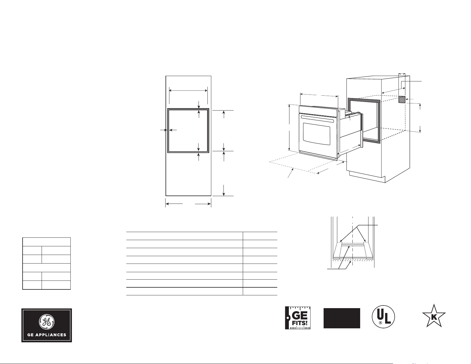
A – Overlap of oven at top of cutout 1-1/4"
B – Overlap of oven over side of edges of cutout 3/4"
C – Overlap of oven at bottom of cutout 1-1/4"
Oven
D – Install depth 23-1/2"
E – Overall height with trim 28-3/4"
F – Overall width 29-3/4"
PT9050
B
30''
A
C
Cutout width
28-1/2" MIN.
28-5/8" MAX.
Recommended
cutout location
from oor
32-1/2"
Cutout height
27-1/4" MIN.
27-5/16" MAX.
23" minimum
door opening
allowance
22" to
bottom of
junction box
Junction box
location
9-1/2"
MAX.
Cutout depth
23-1/2" MIN
Cabinet 30"
A – Overlap of oven at top of cutout 1-1/4"
B – Overlap of oven over side of edges of cutout 3/4"
C – Overlap of oven at bottom of cutout 1-1/4"
Oven
D – Install depth 23-1/2"
E – Overall height with trim 28-3/4"
F – Overall width 29-3/4"
PT9050
B
30''
A
C
Cutout width
28-1/2" MIN.
28-5/8" MAX.
Recommended
cutout location
from oor
32-1/2"
Cutout height
27-1/4" MIN.
27-5/16" MAX.
22" to
bottom of
junction box
Junction box
location
GE Profile
DIMENSIONS AND INSTALLATION INFORMATION (IN INCHES)
MOST 30" WALL CABINETS CAN BE
USED WITH THIS UNIT.
NOTE: These ovens are not approved
for stackable installations. Cabinets
installed adjacent to wall ovens must
have an adhesion spec of at least a 194°F
temperature rating.
Door handle protrudes 3" from door face.
Cabinets and drawers on adjacent 45°
and 90° walls should be placed to avoid
interference with the handle.
Electric wall ovens are not approved for
installation with a plug and receptacle.
They must be hard wired in accordance with
installation instructions.
INSTALLATION I N FORMATI O N :
Before installing, consult installation
instructions packed with product for
current dimensional data.
Side-by-side installations rerquire at least
2" between cutouts.
KW R ATI N G
240V 4.5
208V 3.4
BREAKER SIZE
24 0V 20 Amps
208V 20 Amps
™
Series 30 in. Built-In Single Convection Wall Oven
For answers to your Monogram, GE Café™ Series, GE Profile™ Series or
GE Appliances product questions, visit our website at geappliances.com
or call GE Answer Center® Service, 800.626.2000.
Dimension and
installation information
are shown in inches.
Listed by
Underwriters
Laboratories
Speci fication Revised 4/16
Page 2
PT9050SF
25
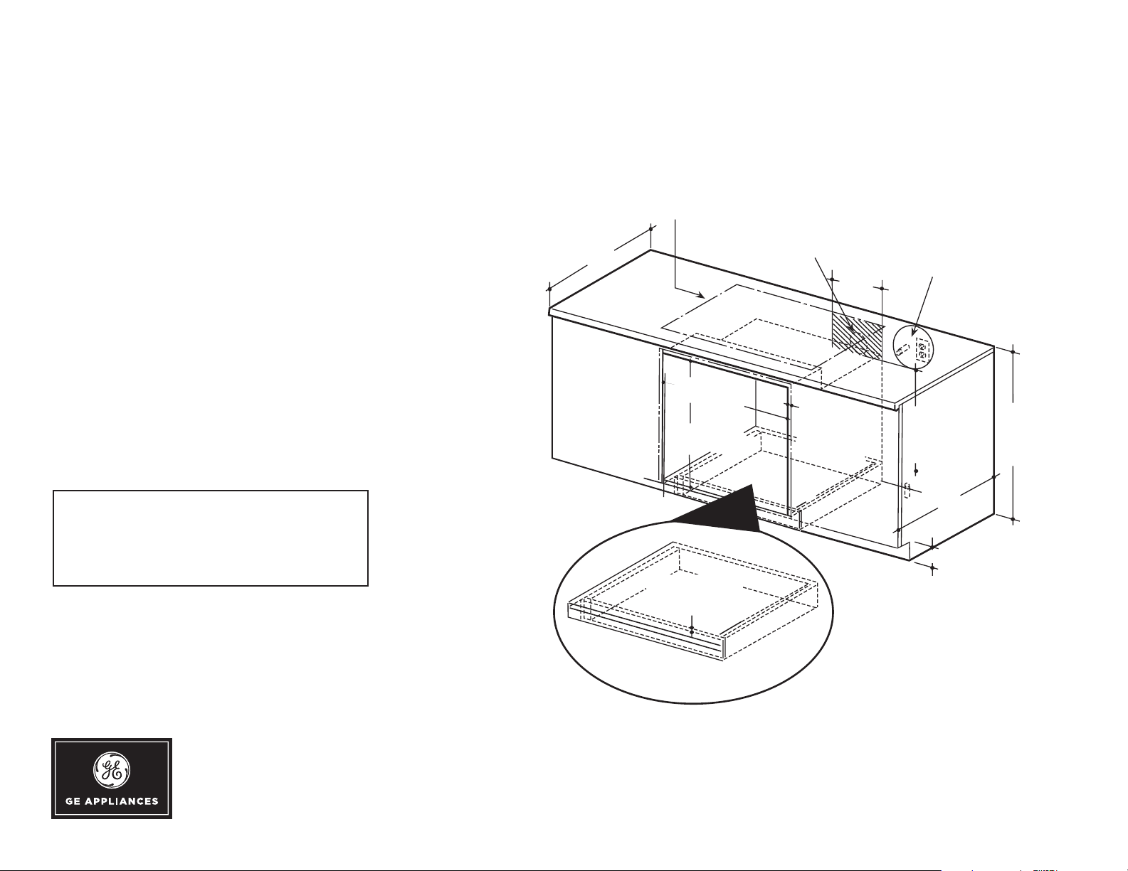
Gas or electric cooktops may be installed over this
oven. See cooktop installation instructions for cutout size.
See label on top of oven for approved cooktop models.
Gas or electric connections
for gas cooktop must be
located in an adjacent
accessible location to the right
240V / 208V
Junction box
location
36"
Typical
countertop
height
24
4
"
Allow 1-1/4"
top/bottom and
1" on sides for
overlap
28 1/2" MIN.
28 5/8" MAX.
9-1/2"
27 1/4" MIN.
27 5/16" MAX.
3/4" Support
platform required
Must Support 200 Lbs.
22" MIN.
Above
support
platform
Side by Side single ovens
Side-by-Side Installations
Install two ovens in separate cutouts.
Center Line
Cutout -
observe all
dimensions and
requirements.
Cutout -
observe all
dimensions and
requirements.
Center Line
30" models
2
" MIN.
27" models
GE Profile
OPTIONAL UNDERCOUNTER DIMENSIONS AND INSTALLATION INFORMATION
NOTE: 36" ribbon cooktop are approved
for use over GE 30" single wall ovens and
warming drawers. 30" ribbon cooktops
are approved for use over 30" and GE 27"
single wall ovens and warming drawers.
Refer to cooktop and wall oven installation
information packed with products for current
dimensional data.
NOTE: Door handle protrudes 3" from door
face. Cabinets and drawers on adjacent 45°
and 90° walls should be placed to avoid
interference with the handle.
INSTALLATION I N FORMATI O N : Before
installing, consult installation instructions
packed with products for current dimensional
data and for alternate installation options.
ELECTRIC WALL OVENS ARE NOT
APPROVED FOR INSTALLATION WITH
A PLUG AND RECEPTACLE. THEY
MUST BE HARD WIRED IN ACCORDANCE
WITH INSTALLATION INSTRUCTIONS.
™
Series 30 in. Built-In Single Convection Wall Oven
For answers to your Monogram, GE Café™ Series, GE Profile™ Series or
GE Appliances product questions, visit our website at geappliances.com
or call GE Answer Center® Service, 800.626.2000.
Speci fication Revised 4/16
Page 3

PT9050SF
GE Profile
FEATURES AND BENEFITS
True European Convection with Direct Air - Bakes evenly as warm
air blows from the top in and around bakeware
WiFi Connect – Wirelessly control oven functions from
your smartphone
Notification lighting – Know the status of your oven functions with
a quick glance
Ten-pass bake element – Even baking is assured with heat that covers
more surface area
Ten-pass dual broil element – Large and small dishes brown evenly
with two, full-coverage elements
Self-clean heavy-duty roller rack – Easily access items with
a rack that glides smoothly
Progressive halogen oven lighting – See what you’re baking
with lights that slowly illuminate the oven
Self-clean with steam clean option – Clean your oven the way
you want
™
Series 30 in. Built-In Single Convection Wall Oven
Glass touch controls – Set temperatures quickly and clean
with little effort
5.0 cu. ft. oven capacity – Cook more dishes at once
Model PT9050SFSS – Stainless steel
GUARANTEED FIT
Replacing a similar wall oven from GE or another brand? GE wall ovens are
guaranteed for an exact fit to make replacement easy
Visit geappliances.com for more info
Speci fication Revised 4/16
 Loading...