

Page 1
PROPANE CONVERSION INSTRUCTIONS
WARNING
Death or serious injury can result from failure to follow
these instructions.
• Service by a qualified service technician only.
• Shut off gas supply and disconnect power before servicing.
• Reconnect all grounding devices after service.
• Replace all parts and panels before operating.
The pressure regulator and the burner orifices are set for
natural gas. To use propane gas, the regulator and burner
orifices must be converted.
WARNING
burners of this range when using propane (bottled) gas
before converting the pressure regulator and burner orifices
for propane gas use. Failure to do so could cause high
flames and toxic fumes which can result in serious injury.
The propane orifices for the cooktop burners are shipped on
the back of the range in a small box.
Propane Conversion Kit
LP
CONVERSION
KIT
TOOLS REQUIRED:
• Adjustable wrench
• 1/2” Open-end wrench
• Phillips head screwdriver
To adjust your range for use with propane gas, follow these
instructions:
1. Disconnect all electrical power, at the main circuit breaker or
fuse box.
2. Shut off the gas supply to the range by closing the manual
shut-off valve.
Explosion Hazard
Do not operate the cooktop or oven
• Flat bladed screwdriver
(blade approximately
3/32” across)
• Nut drivers: 1/4”, 9/32”
or 7mm
Pressure Regulator Gas Valve
NOTICE:
If you are using propane (bottled) gas, all adjustments
described in the following steps must be made before you
make any burner adjustments.
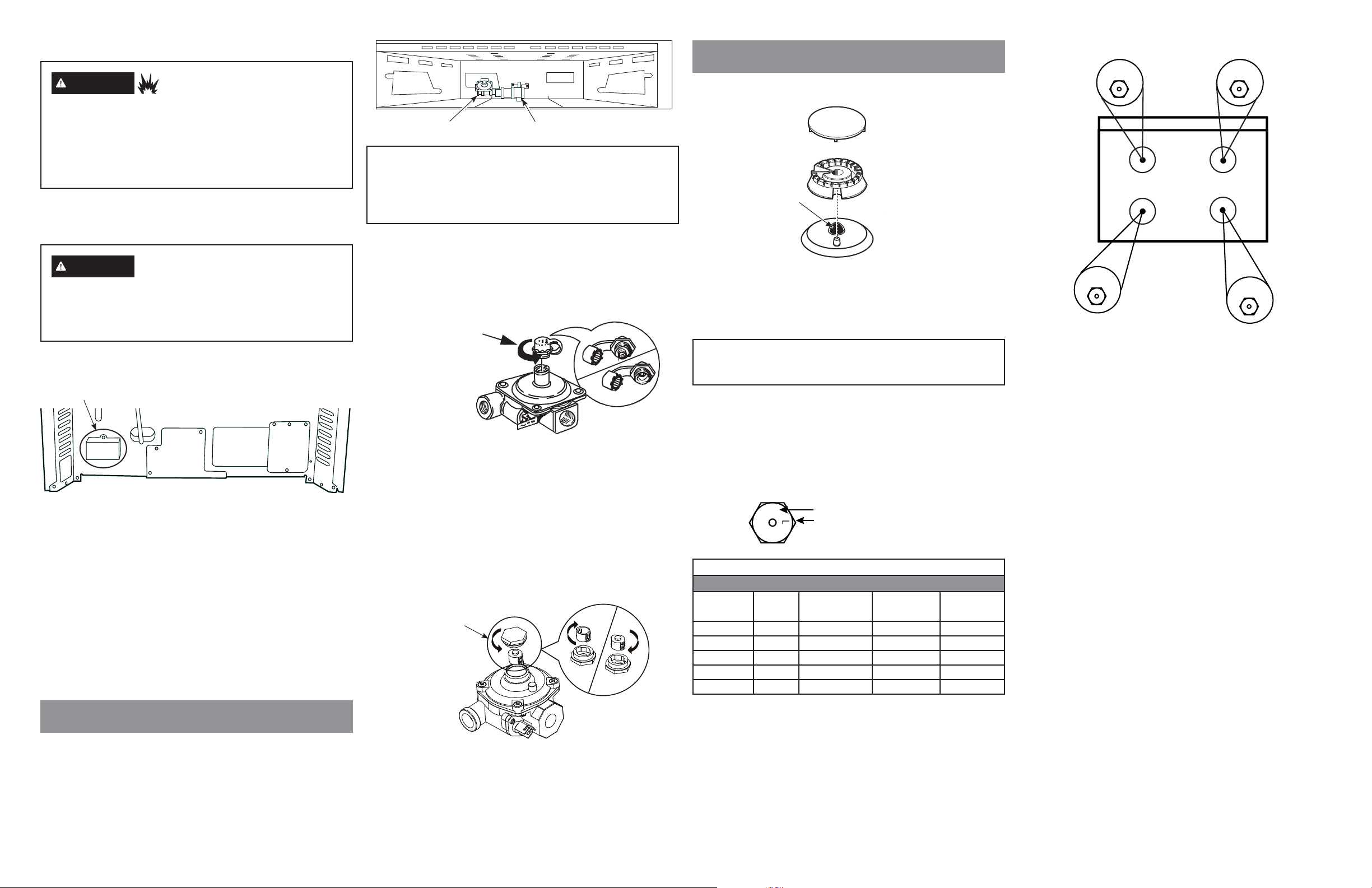
A. If this is your regulator:
1. Use an adjustable wrench to unscrew the hex-nut cap
from the pressure regulator.
2. Completely remove the protective plastic cap off the
threaded metal cap.
Rotate cap counterclockwise to loosen
Regulator style A
3. Turn the metal cap so the type of gas being converted to
is displayed and replace the protective plastic cover.
4. Screw the hex-nut cap back into the regulator.
(Do not over tighten)
B. If this is your regulator:
1. Use an adjustable wrench to unscrew the hex-nut cap
from the pressure regulator.
2. Turn the plastic cap 1/4 turn to disassemble.
Rotate cap counterclockwise to loosen.
NAT
PROPANE
Cap assembly
NAT
PROPANE
CONVERTING THE COOKTOP BURNERS
A. Remove the top grates, burner caps and burner heads.
Burner
cap
Orifice
located
through this
opening
Burner construction
Burner
head
Base
B. Using a 7 mm or 9/32” nut driver, remove the top burner
orifices. These may be accessed through the burner
opening in the base.
NOTICE:
Save these orifices for future conversion back to natural gas.
C. Remove the propane orifices from the box provided. The
propane orifices have the letter “L” on the top.
To aid in identifying the proper location for the propane
orifices during conversion from Natural Gas to Propane
Gas, color codes have been added to the side or top of the
orifice. See the chart below. Each orifice may also show a
series of engraved marks (I, II, III . . .) located on the top.
95
III
BURNER OUTPUT RATINGS: BTU/HR
BTU
BURNER
RF 9,500 0.035” (0.89) Blue/Brown 89L
LF 15,000 0.045” (1.14) Orange/Yellow 114L
RR 12,000 0.039” (0.99) Blue/Magenta 99L
LR 5,000 0.026” (0.66) Red/Yellow 66L
OVEN 16,000 0.048” (1.21) Pink .048
RATE
Denotes 0.95mm Orifice size opening
Denotes LP (Propane)
Propane Gas 10” W.C.P.
ORIFICE
SIZE (mm) COLOR MARKING
D. Install the propane orifices in their precise locations.
Propane
Red/Yellow
LR
Propane
Blue/Magenta
RR
LF RF
Propane
Orange/Yellow
To prevent leakage, make sure the orifice spuds are securely
screwed into the gas supply tubes.
E. Install the old orifice spuds into the metal box or bracket
along with these instructions, and replace onto the back of
the range for possible future conversion.
Propane
Blue/Brown
CONVERTING THE PRESSURE REGULATOR
The pressure regulator is located on the rear of the range.
(Some models will have a metal shield protecting the regulator
that must be removed for conversion and reinstalled when
conversion is complete.) The pressure regulator is located in the
lower, left hand side of the range as viewed from the front left.
Printed in Mexico
Regulator style B
3. Turn the plastic cap over and hook it into the slots.
Rotate cap 1/4 turn to reassemble. The type of gas to be
used should now be visible on the top of the cap.
4. Screw the hex-nut cap back onto the pressure regulator.
PROPANE CONVERSION INSTRUCTIONS
31-11121 06-17 GEA
JGBS62
Page 2
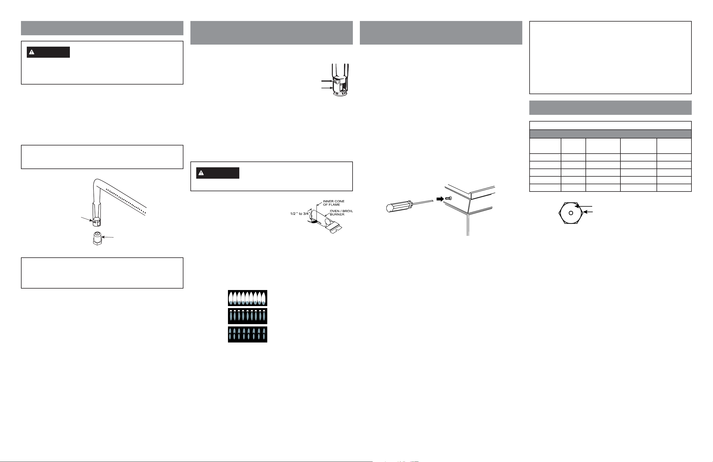
CONVERTING THE OVEN BURNERS
WARNING
before turning on the gas to the oven burner. Failure to
do so could result in serious injury due to high flames and
toxic fumes.
The following adjustments must be made
OVEN BURNER ORIFICE
1. Remove oven door, broil drawer, oven bottom, and burner.
The oven burner orifice is located behind the drawer. On
some models a metal shield must be removed.
2. To convert to propane, replace oven orifice with the one
supplied in kit with range.
NOTICE:
Save these orifices for future conversion back to natural gas.
ADJUSTING AIR SHUTTER SETTINGS
FOR OVEN BURNERS
1. With a Phillips head screwdriver, loosen the screws
securing the air shutter on the bake burner. Adjust the air
shutter to fully open.
2. Turn on the gas.
3. Turn on the electricity.
4. Reinstall the oven door.
5. Turn on the bake burner.
Oven burner flame must be observed with the door closed
to properly check flame characteristics.
6. As you watch the flame with the oven door closed, check
the following through the oven door window.
a. If the flames are yellow, open the air shutter more.
b. If the flames blow away or flutter from the burner, close
the air shutter slightly.
7. Turn bake burner off and repeat with broil burner.
WARNING
If you attempt to measure the inner cone
of the flame, please use caution: burns could result.
Screw
Air shutter
ADJUSTING LOW FLAME SETTING
ON COOKTOP BURNERS
Low setting adjustments must be made with other burners in
operation on a medium setting. This procedure prevents the
low flame from being set too low, resulting in the flame being
extinguished when other burners are turned on.
A. Turn on all surface burners.
B. Turn the knob on the burner being adjusted to “LO”.
C. Remove the knob and insert a small, flat blade screwdriver
into the valve shaft as shown and turn clockwise to fully
tighten down the bypass screw. Repeat for all valves.
D. If flame appears too low or unstable, slowly turn bypass
screw counterclockwise until a stable flame exists for each
burner. Remember, other burners must be turned on to
medium.
E. Additionally, for each burner being adjusted, quickly open
and close the oven door while observing flame. If flame is
extinguished, continue adjusting bypass screw for a larger
flame. Repeat door openings until flame is stable.
F. Replace the knob.
NOTICE:
Once the conversion is complete and confirmed, fill out
the propane sticker and include your name, organization
and date conversion was made. Apply the sticker to
the range near the regulator to alert others in the future
that this appliance has been converted to propane. If
converting back to natural gas from propane, please
remove the sticker so others know the appliance is set to
use natural gas.
ADDITIONAL INFORMATION
BURNER OUTPUT RATINGS: BTU/HR
NG (Natural) Gas 5” W.C.P.
BTU
BURNER
RF 9,500 0.053” (1.36) Green 136N
LF 15,000 0.070” (1.78) Brown 178N
RR 12,000 0.061” (1.55) Red 155N
LR 5,000 0.040” (1.01) White/Purple 101N
OVEN 18,000 0.076” (1.93) None .076
RATE
ORIFICE
SIZE (mm) COLOR MARKING
Oven burner
air shutter
Oven
orifice
NOTICE:
This product cannot be converted to propane by adjusting
the oven orifices. The orifices must be replaced for propane.
8 Checking the flame size:
It should be approximately 1/2”
to 3/4” long for the bake and broil
burners.
The combustion quality of the
burner flames needs to be
determined visually.
NOTE: If burner flames look like (A), further air shutter
adjustment to the bake buner is required. Normal
burner flames should look like (B) or (C), depending
on the type of gas you use. With propane gas, some
yellow tipping on the outer cones is normal.
(A) Yellow flames:
Further Adjustment
Required
(B) Yellow tips on
outer cones:
Normal for Propane Gas
(C) Soft blue flames:
Normal for Natural Gas
Foreign particles in the gas line may cause an orange flame at
first, but this will soon disappear.
9.
When all adjustments are made and the results are
satisfactory:
a. Retighten the air shutter screws.
b. Replace the oven bottom.
c. Replace the storage drawer.
Center adjustment screw for all burners.
198
III
Denotes 1.98mm Orifice size opening
Denotes Natural Gas
N
SPECIAL NOTE:
To convert the oven back to natural gas, reverse the
instructions given in making propane adjustments.
PROPANE CONVERSION INSTRUCTIONS
31-11121 06-17 GEA
JGBS62
 Loading...