

Page 1
GE Home Generator Systems
Not
for
Reproduction
Home Generator System
Installation and
Start-Up Manual
Page 2

Thank you for purchasing this quality-built GE home generator. We’re pleased that you’ve placed your confidence in the
Not
for
Reproduction
GE brand. When operated and maintained according to the instructions in the operator’s manual, your home generator
will provide many years of dependable service.
This manual contains safety information to make you aware of the hazards and risks associated with residential
generator systems and how to avoid them. This generator system is designed and intended only for use as an
optional home standby system that provides an alternate source of electric power and to serve loads such as heating,
refrigeration systems, and communication systems that, when stopped during any power outage, could cause
discomfort or inconvenience. Save these original instructions for future reference.
This generator requires professional installation before use. The installer should follow the instructions completely.
Where to Find Us
You never have to look far to find support and service for your generator. For quick service when you need it most
fill out the information below and keep your original receipt with this manual. You may contact Customer Service at
(888) 575-8226, or click on SERVICE & SUPPORT at www.homestandbygeneratorsystems.com, which provides a list of
authorized dealers.
For Future Reference
Please fill out the information below and keep with your receipt to assist in unit identification for future purchase issues.
DATE OF PURCHASE
GENERATOR
Model Number
Model Revision
Serial Number
ENGINE
Model Number
2
Page 3

Table of Contents
Not
for
Reproduction
Safety Rules. . . . . . . . . . . . . . . . . . . . . . . . . . . . . . . . . . . . . . . . . . . . . . . . . . . . .4
Important Safety Instructions. . . . . . . . . . . . . . . . . . . . . . . . . . . . . . . . . . . . . . . . . . . . . . . . . . . . . . 4
Installation . . . . . . . . . . . . . . . . . . . . . . . . . . . . . . . . . . . . . . . . . . . . . . . . . . . . .7
Home Owner Responsibilities . . . . . . . . . . . . . . . . . . . . . . . . . . . . . . . . . . . . . . . . . . . . . . . . . . . . . . 7
Installing Dealer/Contractor Responsibilities . . . . . . . . . . . . . . . . . . . . . . . . . . . . . . . . . . . . . . . . 7
Cold Weather Kit . . . . . . . . . . . . . . . . . . . . . . . . . . . . . . . . . . . . . . . . . . . . . . . . . . . . . . . . . . . . . . . . . 7
Unpacking Precautions. . . . . . . . . . . . . . . . . . . . . . . . . . . . . . . . . . . . . . . . . . . . . . . . . . . . . . . . . . . . 8
Delivery Inspection . . . . . . . . . . . . . . . . . . . . . . . . . . . . . . . . . . . . . . . . . . . . . . . . . . . . . . . . . . . . . . . 8
Shipment Contents . . . . . . . . . . . . . . . . . . . . . . . . . . . . . . . . . . . . . . . . . . . . . . . . . . . . . . . . . . . . . . . 8
Installation Checklist. . . . . . . . . . . . . . . . . . . . . . . . . . . . . . . . . . . . . . . . . . . . . . . . . . . . . . . . . . . . . . 9
Generator Placement . . . . . . . . . . . . . . . . . . . . . . . . . . . . . . . . . . . . . . . . . . . . . . . . . . . . . . . . . . . . . 9
Placement of Standby Generator to Reduce the Risk of Carbon Monoxide Poisoning . . . 10
Placement of Standby Generator to Reduce the Risk of Fire . . . . . . . . . . . . . . . . . . . . . . . . . . 12
Other General Location Guidelines . . . . . . . . . . . . . . . . . . . . . . . . . . . . . . . . . . . . . . . . . . . . . . . . 14
National Fire Protection Association (NFPA) Standard NFPA 37
Requirements and Testing. . . . . . . . . . . . . . . . . . . . . . . . . . . . . . . . . . . . . . . . . . . . . . . . . . . . . . . . 14
Electrical and Fuel Inlet Locations . . . . . . . . . . . . . . . . . . . . . . . . . . . . . . . . . . . . . . . . . . . . . . . . . 15
Lifting the Generator. . . . . . . . . . . . . . . . . . . . . . . . . . . . . . . . . . . . . . . . . . . . . . . . . . . . . . . . . . . . . 15
Access Ports . . . . . . . . . . . . . . . . . . . . . . . . . . . . . . . . . . . . . . . . . . . . . . . . . . . . . . . . . . . . . . . . . . . . 16
The Gaseous Fuel System. . . . . . . . . . . . . . . . . . . . . . . . . . . . . . . . . . . . . . . . . . . . . . . . . . . . . . . . . 18
System Connectors . . . . . . . . . . . . . . . . . . . . . . . . . . . . . . . . . . . . . . . . . . . . . . . . . . . . . . . . . . . . . . 21
Generator AC Connection System . . . . . . . . . . . . . . . . . . . . . . . . . . . . . . . . . . . . . . . . . . . . . . . . . 22
Grounding the Generator. . . . . . . . . . . . . . . . . . . . . . . . . . . . . . . . . . . . . . . . . . . . . . . . . . . . . . . . . 22
Utility Circuit Connection. . . . . . . . . . . . . . . . . . . . . . . . . . . . . . . . . . . . . . . . . . . . . . . . . . . . . . . . . 23
Transfer Switch Communication . . . . . . . . . . . . . . . . . . . . . . . . . . . . . . . . . . . . . . . . . . . . . . . . . . 23
Fault Detection System . . . . . . . . . . . . . . . . . . . . . . . . . . . . . . . . . . . . . . . . . . . . . . . . . . . . . . . . . . 24
System Control Panel . . . . . . . . . . . . . . . . . . . . . . . . . . . . . . . . . . . . . . . . . . . . . . . . . . . . . . . . . . . . 24
Concrete Slab (Optional). . . . . . . . . . . . . . . . . . . . . . . . . . . . . . . . . . . . . . . . . . . . . . . . . . . . . . . . . . 25
Final Installation Considerations . . . . . . . . . . . . . . . . . . . . . . . . . . . . . . . . . . . . . . . . . . . . . . . . . . 26
Initial Start-up (No Load) . . . . . . . . . . . . . . . . . . . . . . . . . . . . . . . . . . . . . . . . . . . . . . . . . . . . . . . . . 27
Engine Adjustment . . . . . . . . . . . . . . . . . . . . . . . . . . . . . . . . . . . . . . . . . . . . . . . . . . . . . . . . . . . . . . 28
Schematic / Wiring Diagrams. . . . . . . . . . . . . . . . . . . . . . . . . . . . . . . . . . . . . . . . . . . . . . . . . . . . . 30
Operation. . . . . . . . . . . . . . . . . . . . . . . . . . . . . . . . . . . . . . . . . . . . . . . . . . . . . 34
Automatic Operation Sequence . . . . . . . . . . . . . . . . . . . . . . . . . . . . . . . . . . . . . . . . . . . . . . . . . . . 34
Setting Exercise Timer. . . . . . . . . . . . . . . . . . . . . . . . . . . . . . . . . . . . . . . . . . . . . . . . . . . . . . . . . . . . 35
Installation Inspection . . . . . . . . . . . . . . . . . . . . . . . . . . . . . . . . . . . . . . . . . . . . . . . . . . . . . . . . . . . 36
3
Page 4
Safety Rules
Not
for
Reproduction
Important Safety Instructions
SAVE THESE INSTRUCTIONS - This manual contains
important instructions that should be followed during
installation and maintenance of the generator and batteries.
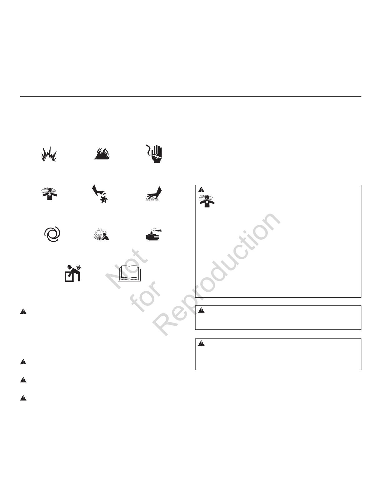
Safety Symbols and Meanings
Explosion
Toxic Fumes
Lift Hazard
Fire
Rotating Parts
Read Manual
Electrical Shock
Hot Surface
Chemical BurnExplosive PressureAuto Start
The manufacturer cannot possibly anticipate every possible
circumstance that might involve a hazard. The warnings
in this manual, and the tags and decals affixed to the unit
are, therefore, not all-inclusive. If you use a procedure, work
method or operating technique that the manufacturer does
not specifically recommend, you must satisfy yourself that it
is safe for you and others. You must also make sure that the
procedure, work method or operating technique that you
choose does not render the generator system unsafe.
WARNING Running engine gives off carbon monoxide, an
odorless, colorless, poison gas.
Breathing carbon monoxide could result in death, serious
injury, headache, fatigue, dizziness, vomiting, confusion,
seizures, nausea or fainting.
• Operate this product ONLY outdoors in an area that will not
accumulate deadly exhaust gas.
• Keep exhaust gas away from any windows, doors, ventilation
intakes, soffit vents, crawl spaces, open garage doors or other
openings that can allow exhaust gas to enter inside or be drawn
into a potentially occupied building or structure.
• Carbon monoxide detector(s) MUST be installed and maintained
indoors according to the manufacturer’s instructions/
recommendations. Smoke alarms cannot detect carbon
monoxide gas.
The safety alert symbol indicates a potential personal
injury hazard. A signal word (DANGER, WARNING, or
CAUTION) is used with the alert symbol to designate a degree
or level of hazard seriousness. A safety symbol may be used
to represent the type of hazard. The signal word NOTICE is
used to address practices not related to personal injury.
DANGER indicates a hazard which, if not avoided, will
result in death or serious injury.
WARNING indicates a hazard which, if not avoided, could
result in death or serious injury.
CAUTION indicates a hazard which, if not avoided, could
result in minor or moderate injury.
NOTICE addresses practices not related to personal injury.
4
WARNING The engine exhaust from this product contains
chemicals known to the State of California to cause cancer, birth
defects, or other reproductive harm.
WARNING Certain components in this product and related
accessories contain chemicals known to the State of California
to cause cancer, birth defects, or other reproductive harm. Wash
hands after handling.
Page 5
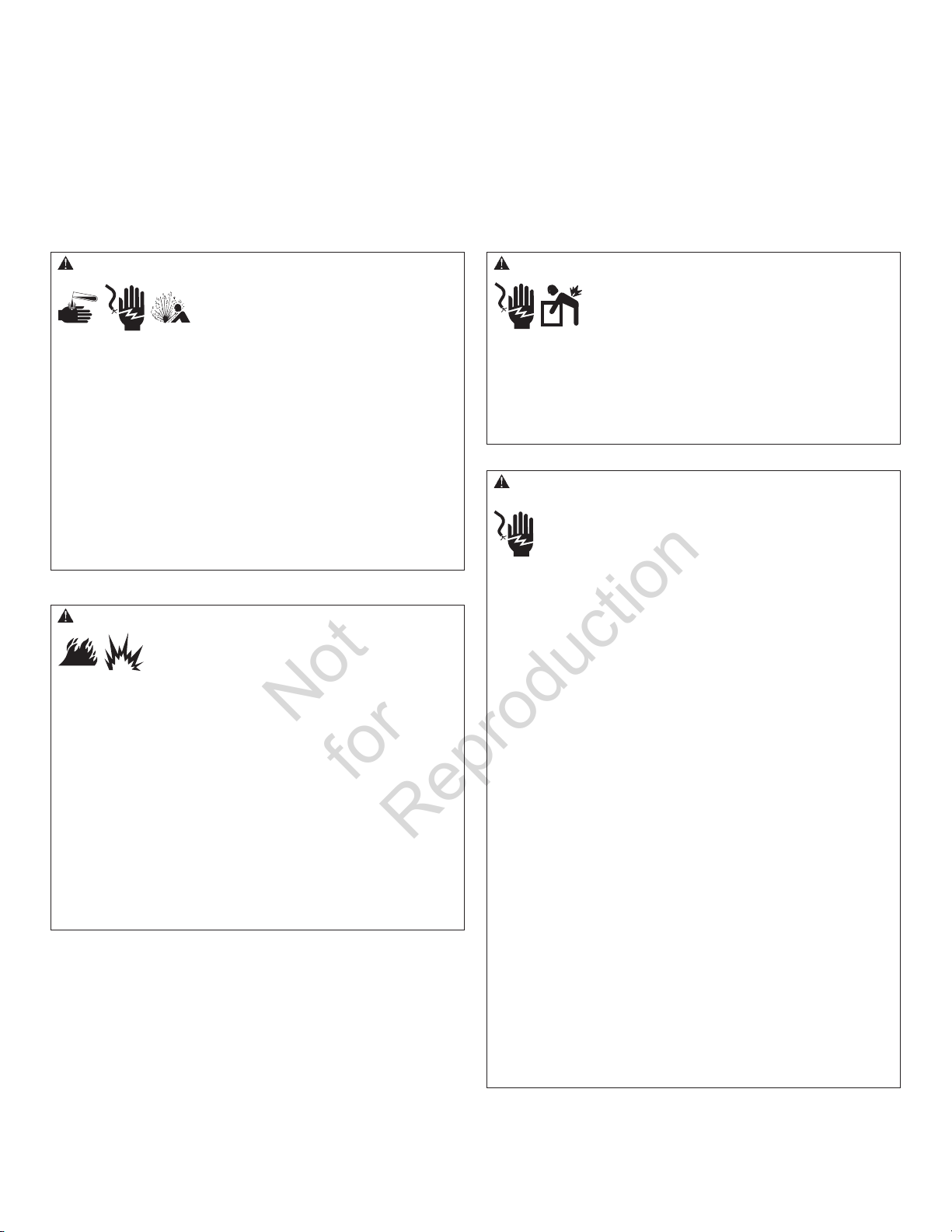
WARNING Storage batteries give off explosive hydrogen gas
Not
for
Reproduction
during recharging.
Slightest spark will ignite hydrogen and
cause explosion, resulting in death, serious
injury and/or property damage.
Battery electrolyte fluid contains acid and is extremely caustic.
Contact with battery contents could cause severe chemical burns.
A battery presents a risk of electrical shock and high short
circuit current.
• DO NOT dispose of battery in a fire. Recycle battery.
• DO NOT allow any open flame, spark, heat, or lit cigarette during
and for several minutes after charging a battery.
• DO NOT open or mutilate the battery.
• Wear protective goggles, rubber apron, rubber boots and
rubber gloves.
• Remove watches, rings, or other metal objects.
• Use tools having insulated handles.
WARNING Propane and Natural Gas are extremely flammable
and explosive, which could cause burns, fire or
explosion resulting in death, serious injury and/or
property damage.
• Install the fuel supply system according to NFPA 37 and other
applicable fuel-gas codes.
• Before placing the generator into service, the fuel system lines
must be properly purged and leak tested.
• After the generator is installed, you should inspect the fuel
system periodically.
• NO leakage is permitted.
• DO NOT operate engine if smell of fuel is present or other
explosive conditions exist.
• DO NOT smoke around the generator. Wipe up any oil spills
immediately. Ensure that no combustible materials are left in the
generator compartment. Keep the area near the generator clean
and free of debris.
WARNING Hazardous Voltage - Contact with power lines could
cause electric shock or burn, resulting in death or
serious injury.
Lifting Hazard / Heavy Object - Could result in
serious injury.
• If lifting or hoisting equipment is used, DO NOT contact any
power lines.
• DO NOT lift or move generator without assistance.
• Use lifting pipes as described in Lifting the Generator.
• DO NOT lift unit by roof as damage to generator will occur.
WARNING Generator produces hazardous voltage.
Failure to properly ground generator could result
in electrocution.
Failure to isolate generator from utility power could result
in death or serious injury to electric utility workers due to
backfeed of electrical energy.
• When using generator for backup power, notify utility company.
• DO NOT touch bare wires or bare receptacles.
• DO NOT use generator with electrical cords which are worn,
frayed, bare or otherwise damaged.
• DO NOT handle generator or electrical cords while standing in
water, while barefoot, or while hands or feet are wet.
• If you must work around a unit while it is operating, stand on an
insulated dry surface to reduce the risk of a shock hazard.
• DO NOT allow unqualified persons or children to operate or
service generator.
• In case of an accident caused by electrical shock, immediately
shut down the source of electrical power and contact the local
authorities. Avoid direct contact with the victim.
• Despite the safe design of the residential generator, operating
this equipment imprudently, neglecting its maintenance or being
careless could cause possible injury or death.
• Remain alert at all times while working on this equipment.
Never work on the equipment when you are physically or
mentally fatigued.
• Before performing any maintenance on the generator, disconnect
the battery cable indicated by a NEGATIVE, NEG or (-) first. When
finished, reconnect that cable last.
• After your system is installed, the generator may crank and start
without warning any time there is a power failure. To prevent
possible injury, always set the generator’s system switch to OFF,
remove the service disconnect from the disconnect box AND
remove the 15 Amp fuse BEFORE working on the equipment.
5
Page 6
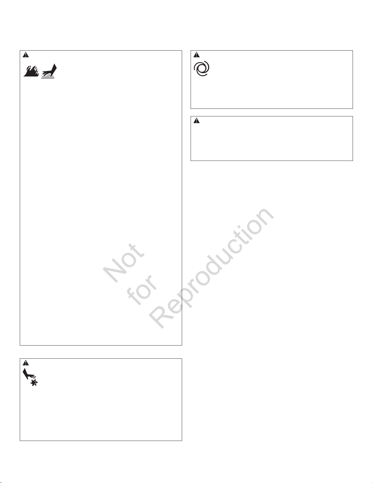
WARNING Exhaust heat/gases could ignite combustibles or
Not
for
Reproduction
structures resulting in death, serious injury and/or
property damage.
Contact with muffler area could cause burns
resulting in serious injury.
• DO NOT touch hot parts and AVOID hot exhaust gases.
• Allow equipment to cool before touching.
• DO NOT place weatherproof enclosure opposite exhaust side closer
than 18 inches (0.5 m) from any structure.
• Exhaust outlet side of weatherproof enclosure must have at least
5 ft (1.5 m) minimum clearance from any structure, shrubs, trees or
any kind of vegetation.
• Standby generator weatherproof enclosure must be at least 5 ft
from windows, doors, any wall opening, shrubs or vegetation over
12 inches (30.5 cm) in height.
• Standby generator weatherproof enclosure must have a minimum
of 4 feet (1.2 m) overhead clearance from any structure, overhang
or trees.
• DO NOT place weatherproof enclosure under a deck or other type
of structure that may confine airflow.
• USE ONLY flexible steel fuel line provided. Connect provided fuel
line to generator, DO NOT use with or substitute any other flexible
fuel line.
• Smoke detector(s) MUST be installed and maintained indoors
according to the manufacturer’s instructions/ recommendations.
Carbon monoxide alarms cannot detect smoke.
• Keep at least minimum distances shown in Generator Placement
to insure for proper generator cooling and maintenance
clearances.
• It is a violation of California Public Resource Code, Section 4442,
to use or operate the engine on any forest-covered, brushcovered, or grass-covered land unless the exhaust system is
equipped with a spark arrester, as defined in Section 4442,
maintained in effective working order. Other states or federal
jurisdictions may have similar laws.
Contact the original equipment manufacturer, retailer, or dealer to
obtain a spark arrester designed for the exhaust system installed
on this engine.
• Replacement parts must be the same and installed in the same
position as the original parts.
WARNING Starter and other rotating parts could entangle
hands, hair, clothing, or accessories resulting in
serious injury.
CAUTION Installing the 15A fuse could cause the engine
to start at any time without warning resulting in minor or
moderate injury.
• Observe that the 15 Amp fuse has been removed from the control
panel for shipping.
• DO NOT install this fuse until all plumbing and wiring has been
completed and inspected.
CAUTION Excessively high operating speeds could result in
minor injury and/or equipment damage.
Excessively low speeds impose a heavy load on generator.
• DO NOT tamper with governed speed. Generator supplies correct
rated frequency and voltage when running at governed speed.
• DO NOT modify generator in any way.
NOTICE Improper treatment of generator could damage it and
shorten its life.
• Use generator only for intended uses.
• If you have questions about intended use, contact your
authorized dealer.
• Operate generator only on level surfaces.
• Adequate, unobstructed flow of cooling and ventilating air is
critical for correct generator operation.
• The access panels/door must be installed whenever the unit
is running.
• DO NOT expose generator to excessive moisture, dust, dirt, or
corrosive vapors.
• Remain alert at all times while working on this equipment.
Never work on the equipment when you are physically or
mentally fatigued.
• DO NOT start engine with air cleaner or air cleaner cover removed.
• DO NOT insert any objects through cooling slots.
• DO NOT use the generator or any of its parts as a step. Stepping
on the unit could cause stress and break parts. This may result in
dangerous operating conditions from leaking exhaust gases, fuel
leakage, oil leakage, etc.
• If connected devices overheat, turn them off and disconnect them
from generator.
• Shut off generator if:
-electrical output is lost;
-equipment sparks, smokes, or emits flames;
-unit vibrates excessively;
-unit makes unusual noises.
• NEVER operate generator without protective housings, covers, or
guards in place.
• DO NOT wear loose clothing, jewelry or anything that could be
caught in the starter or other rotating parts.
• Tie up long hair and remove jewelry.
• Before servicing, remove 15 Amp fuse from control panel and
disconnect Negative (NEG or -) battery cable.
6
Page 7
Installation
Not
for
Reproduction
This product is intended for use as an optional home
generator system which provides an alternate source
of electric power and to serve loads such as heating,
refrigeration systems, and communication systems that,
when stopped during any power outage, could cause
discomfort or inconvenience. This product does not qualify
for emergency standby as defined by NFPA 70 (NEC).
Home Owner Responsibilities
• Read and follow the instructions given in the
operator’s manual.
• Follow a regular schedule in maintaining, caring for
and using your home generator, as specified in the
operator’s manual.
Installing Dealer/Contractor Responsibilities
Every effort has been made to ensure that information in this
manual is accurate and current. However, we reserve the
right to change, alter, or otherwise improve the product and
this document at any time without prior notice.
Only current licensed electrical and plumbing professionals
should attempt home generator system installations.
Installations must strictly comply with all applicable codes,
industry standards, laws and regulations.
• Carbon monoxide detector(s) MUST be installed and
maintained indoors according to the manufacturer’s
instructions/ recommendations. Smoke alarms
cannot detect carbon monoxide gas.
• Read and observe the safety rules.
• Install only an UL approved transfer switch that is
compatible with the generator.
• Read and follow the instructions given in this
installation and start-up manual.
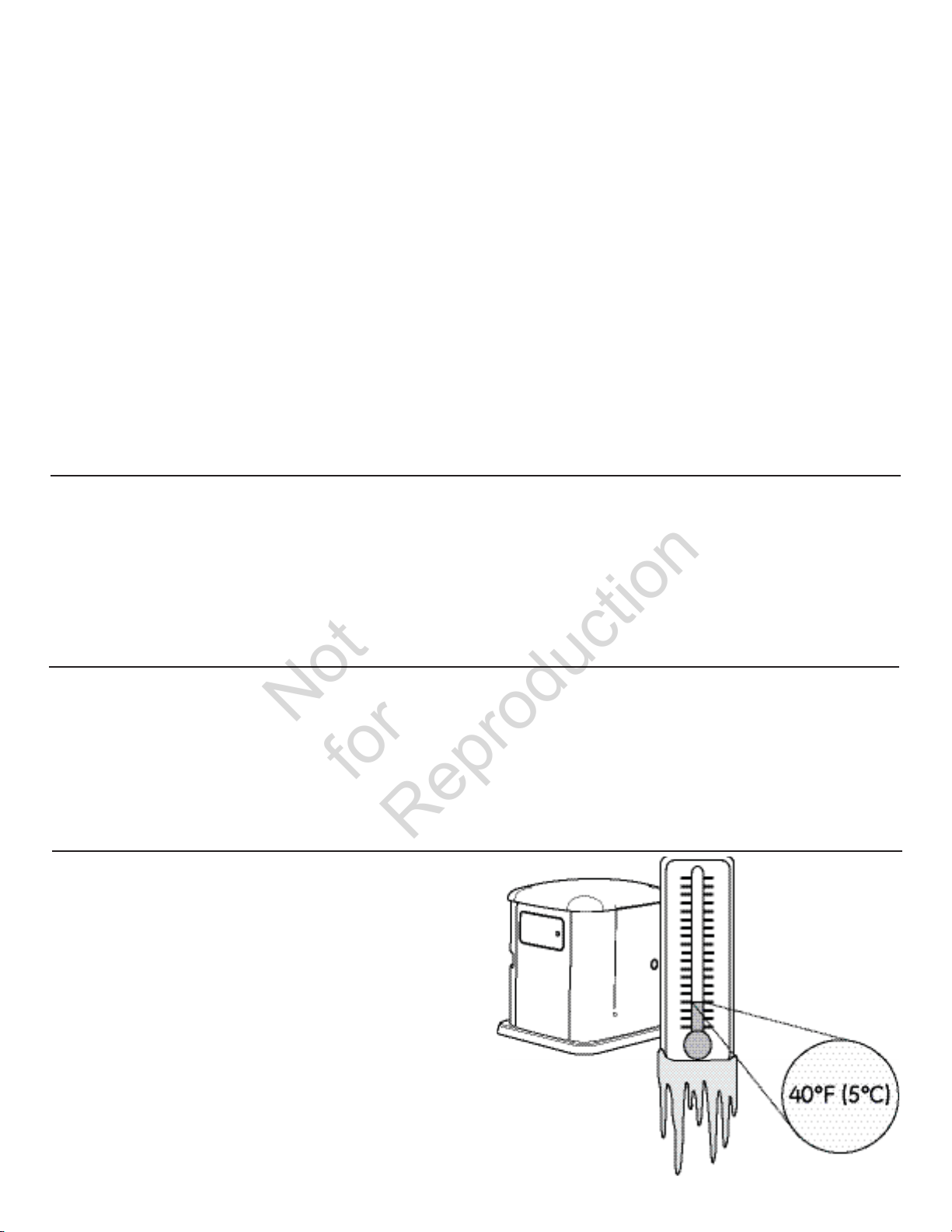
Cold Weather Kit
If operating the generator below 40°F (5°C), it is HIGHLY
RECOMMENDED that a Model 6030 Cold Weather Kit
(includes oil warmer and battery warmer) be installed.
These items are available at your local servicing dealer.
If you need more information on this matter, please call
(888) 575-8226, between 8:00 AM and 5:00 PM CT.
• Installation must strictly comply with all applicable
codes, industry standards, laws, and regulations.
• Allow sufficient room on all sides of the generator for
maintenance and servicing.
7
Page 8

Unpacking Precautions
Not
for
Reproduction
Avoid damage from dropping, bumping, collision, etc. Store
and unpack carton with the proper side up, as noted on the
shipping carton.
Delivery Inspection
After removing the carton, carefully inspect the generator for
any damage that may have occurred during shipment.
If loss or damage is noted at time of delivery, have the
person(s) making delivery note all damage on the freight bill
and affix his signature under the consignor’s memo of loss or
damage. If loss or damage is noted after delivery, separate
the damaged materials and contact the carrier for claim
procedures. Missing or damaged parts are not warranted.
Shipment Contents
The home generator system is supplied with:
• Fully-serviced oil/lubricating system
• Flexible steel fuel line
• Installation and start-up manual
• Operator’s manual
• Spare access door keys
• Spare 15 Amp ATO-type fuse
• Two pin control panel connector
• Ten pin control panel connector
• Lifting hole plugs (4)
• LP conversion jet
Not included:
• Carbon monoxide detector(s)
• Starting battery
• Connecting wire and conduit
• Fuel supply valves/plumbing
• Crane, lifting straps, chains or cables
• Two 48” lengths of 1” pipe (NOT conduit)
• Torque screwdriver, 5 to 50 inch-pound range
• Voltage/frequency meter
8
Page 9
Installation Checklist
Not
for
Reproduction
Proper installation of the home generator requires the
completion of the following tasks:
Carbon Monoxide (CO) Detector
Carbon Monoxide (CO) detector in working order.
Placement
Required permits have been obtained.
Generator placed in a Carbon Monoxide (CO) safe
zone. See Placement of Standby Generator to
Reduce the Risk of Carbon Monoxide Poisoning.
Generator placed in a fire safe zone. See Placement
of Standby Generator to Reduce the Risk of Fire.
Generator placed in a water damage safe zone. See
Other General Location Guidelines.
Generator placed in a utility safe zone. See Other
General Location Guidelines.
Generator placed in a debris free zone. See Other
General Location Guidelines.
Fuel
Generator is connected to fuel source with flexible
fuel line, has no fuel leaks and conforms to local
codes. See The Gaseous Fuel System.
Proper fuel pressure has been measured with all gas
appliances operating. See The Gaseous Fuel System.
Fuel system has been configured for the proper fuel
supply: Natural gas (NG) or liquefied petroleum ( LP)..
See Fuel Conversion.
Electrical
Generator neutral is connected to Automatic
Transfer Switch. See Generator AC Connection
System.
Generator is grounded. See Grounding the
Generator is connected to the transfer switch with
Dipswitches in most transfer switches must be set
Operation
Cold weather kit is installed, if required. See Cold
Correct battery type is installed and fully charged.
Generator engine oil level is at full mark. See Final
Utility was shut off to test the operation of generator
Generator.
Generator is connected to the transfer switch with
the specified wiring. See Utility Circuit Connection
and Transfer Switch Communication.
the specified wiring. #18AWG twisted pair wiring
from the generator control panel to the transfer
switch is installed in a separate conduit from
high voltage wires unless the insulation rating on
all wiring is rated for 600V See Transfer Switch
Communication.
to correspond to the wattage of the generator. See
Transfer Switch Operator/Installation Manual.
Weather Kit.
See Final Installation Considerations.
Installation Considerations.
and transfer switch. Note any fault codes and make
corrections as required.
Generator Placement
Before installing the generator, consult with the homeowner
and convey the following requirements, which must be
satisfied before the installation is complete.
There are two equally important safety concerns in regards
to carbon monoxide poisoning and fire. There are also
several general location guidelines that must all be met
before the installation is considered complete.
WARNING Running engine gives off carbon monoxide, an
odorless, colorless, poison gas.
Breathing carbon monoxide could result in death, serious
injury, headache, fatigue, dizziness, vomiting, confusion,
seizures, nausea or fainting.
• Operate this product ONLY outdoors in an area that will not
accumulate deadly exhaust gas.
• Keep exhaust gas away from any windows, doors, ventilation
intakes, soffit vents, crawl spaces, open garage doors or other
openings that can allow exhaust gas to enter inside or be drawn
into a potentially occupied building or structure.
• Carbon monoxide detector(s) MUST be installed and maintained
indoors according to the manufacturer’s instructions/
recommendations. Smoke alarms cannot detect carbon
monoxide gas.
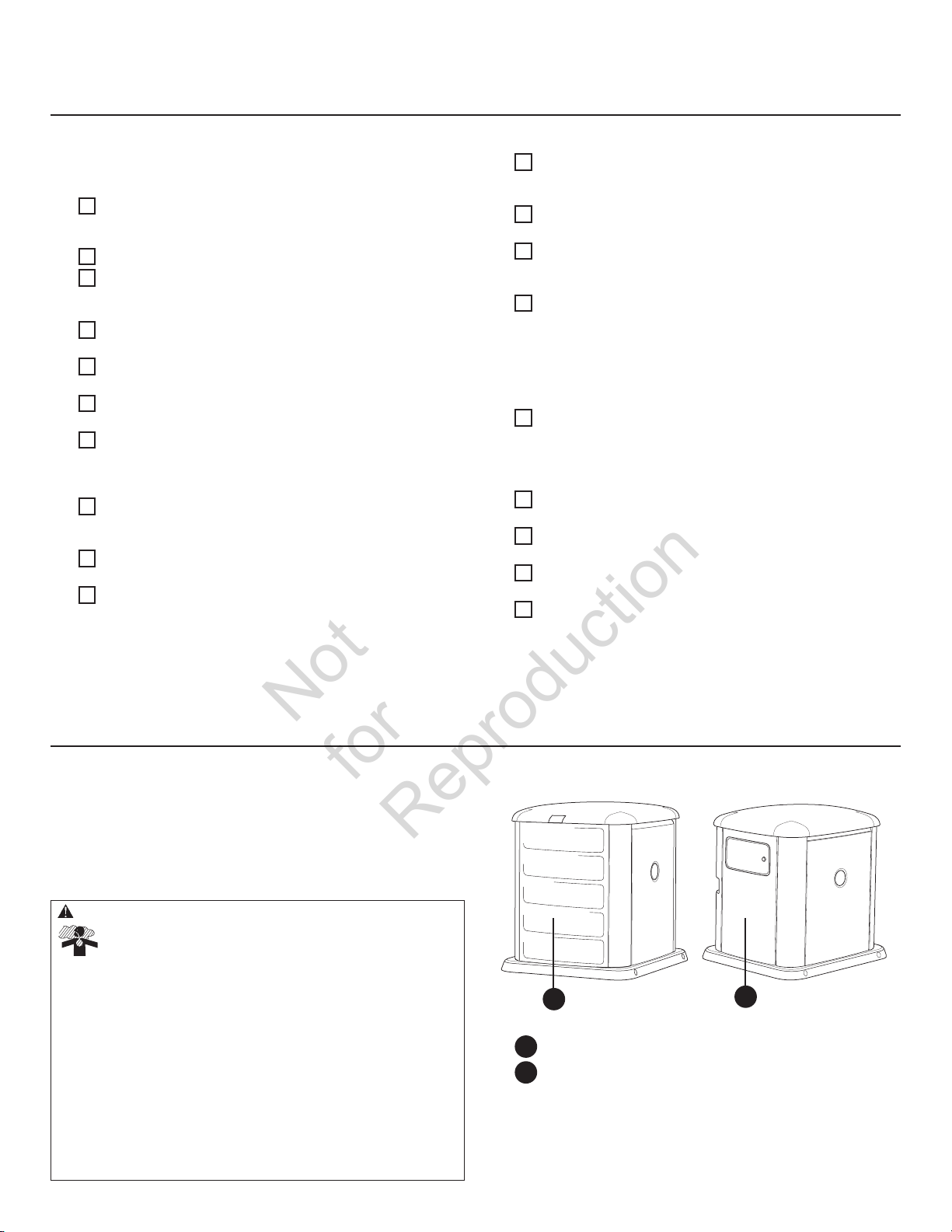
Exhaust Side of the Generator
A
Exhaust outlet side of weatherproof enclosure.
A
Weatherproof enclosure opposite exhaust side.
B
B
9
Page 10
Placement of Standby Generator to
B
D
E
F
G
C
Not
for
Reproduction
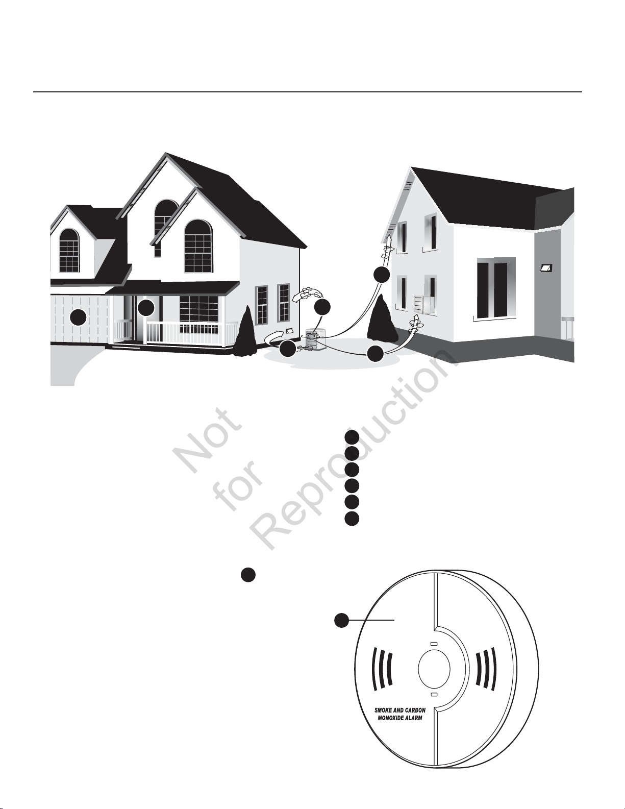
REDUCE THE RISK OF CARBON MONOXIDE POISONING
The arrows in the figure below point to POTENTIAL points of entry for Carbon Monoxide Gas.
B
All fossil fuel burning equipment, such as standby
generators, contains carbon monoxide (CO) gas in the engine
exhaust. CO gas is odorless, colorless and tasteless and is
unlikely to be noticed until a person is overcome. CO gas can
kill you so it is required that the following is included as part
of the installation:
• Install generator outdoors in an area that will not
accumulate deadly exhaust gas.
• DO NOT install generator where exhaust gas could
accumulate and enter inside or be drawn into a
potentially occupied building or structure.
• By law it is required in many states to have a Carbon
Monoxide (CO) detector in operating condition in
your home. Carbon monoxide detector(s)
be installed and maintained indoors according to
the manufacturer’s instructions/ recommendations.
A CO monitor is an electronic device that detects
hazardous levels of CO. When there is a buildup of
CO, the monitor will alert the occupants by flashing
visual indicator light and alarm. Smoke alarms cannot
detect CO gas.
• Your neighbor(s) home may be exposed to the engine
exhaust from your standby generator and must be
considered when installing your standby generator.
A
MUST
• Ensure exhaust gas is kept away from:
windows
B
doors
C
ventilation intakes
D
E
soffit vents
F
garage doors
G
crawl spaces or other openings that can allow
exhaust gas to enter inside or be drawn into a
potentially occupied building or structure.
A
10
Page 11
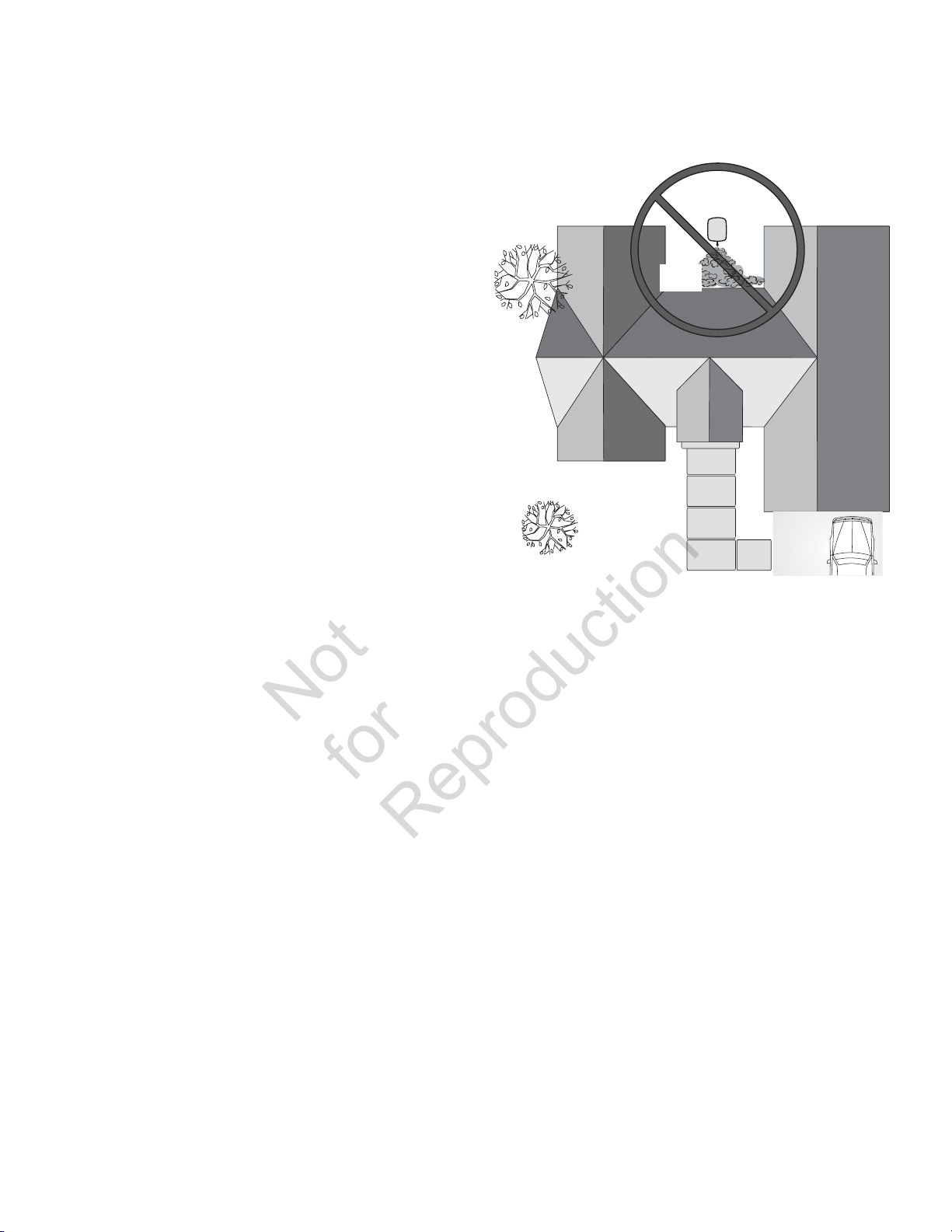
• Direct the standby generator exhaust away from or
Not
for
Reproduction
parallel to the building or structure. DO NOT direct the
generator exhaust towards a potentially occupied
building, structure, windows, doors, ventilation intakes,
soffit vents, crawl spaces, open garage doors or other
openings where exhaust gas could accumulate and
enter inside or be drawn into a potentially occupied
building or structure.
• DO NOT place standby generator in any area where
leaves or debris normally accumulates. Position
standby generator in an area where winds will carry
the exhaust gas away from any potentially occupied
building or structure.
Standby
Generator
Exhaust
Gas
11
Page 12
Placement of Standby Generator to REDUCE THE RISK OF FIRE
Not
for
Reproduction
The National Fire Protection Association (NFPA) standard
NFPA 37 establishes criteria for minimizing the hazard
of fire during the installation and operation of stationary
combustion engines. NFPA 37 limits the spacing of an
enclosed generator from openings in walls, structures and
combustible materials outside the enclosure.
The placement requirements provided are based on
compliance to NFPA 37 2010 section 4.1.4 and a full-scale
demonstration fire test. Details of compliance testing can be
found in section National Fire Protection Association (NFPA)
standard NFPA 37 requirements and testing.
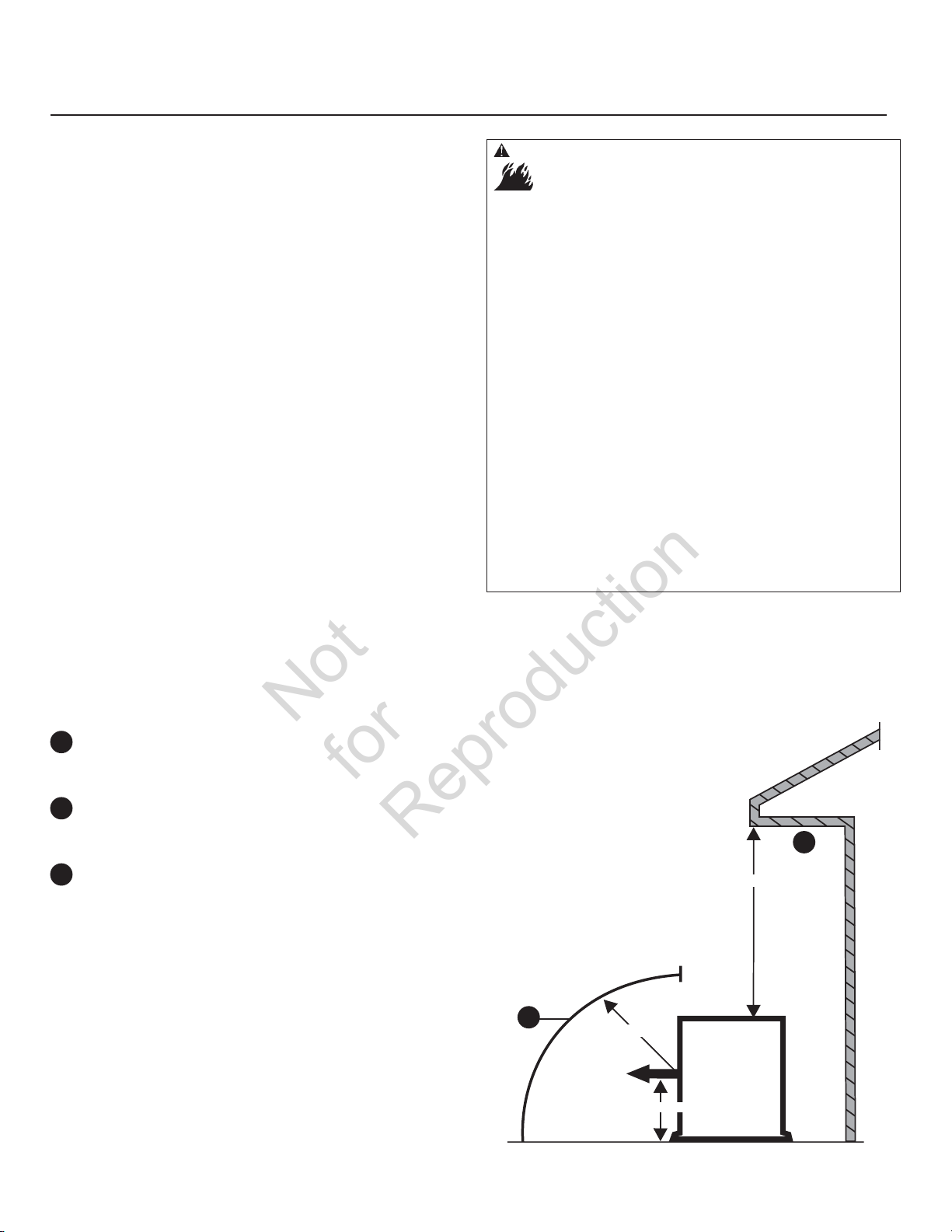
WARNING Exhaust heat/gases could ignite combustibles or
structures resulting in death, serious injury and/or property
damage.
• DO NOT place weatherproof enclosure opposite exhaust side closer
than 18 inches (0.5 m) from any structure.
• Exhaust outlet side of weatherproof enclosure must have at least
5 ft (1.5 m) minimum clearance from any structure, shrubs, trees or
any kind of vegetation.
• Standby generator weatherproof enclosure must be at least
5 ft (1.5 m) from windows, doors, any wall opening, shrubs or
vegetation over 12 inches (30.5 cm) in height.
• Standby generator weatherproof enclosure must have a minimum
of 4 feet (1.2 m) overhead clearance from any structure, overhang
or trees.
• DO NOT place weatherproof enclosure under a deck or other type
of structure that may confine airflow.
• USE ONLY flexible steel fuel line provided. Connect provided fuel
line to generator, DO NOT use with or substitute any other flexible
fuel line.
• Smoke detector(s) MUST be installed and maintained indoors
according to the manufacturer’s instructions/ recommendations.
Carbon monoxide alarms cannot detect smoke.
• DO NOT place weatherproof enclosure in manner other than shown
in illustrations.
Examples of standby generator locations to reduce the
risk of fire:
Legend for Generator Locations to reduce the risk of fire.
Standby weatherproof enclosure must be at least 5 ft
A
(1.5 m) from windows, doors, any wall opening, shrubs
or vegetation over 12 inches (30.5 cm) in height.
Exhaust outlet side of weatherproof enclosure must
B
have at least 5 ft (1.5 m) minimum clearance from any
structure, shrubs, trees or any kind of vegetation.
Standby weatherproof enclosure must have a
C
minimum of 4 feet (1.2 m) overhead clearance from
any structure, overhang or trees.
NOTICE DO NOT place weatherproof enclosure under a deck
or other type of covered structure that may confine airflow.
Vertical Clearances
B
Exhaust
Direction
Center of Exhaust Panel
5 ft (1.5 m)
Structure
C
4 ft (1.2 m)
Standby
12
Page 13
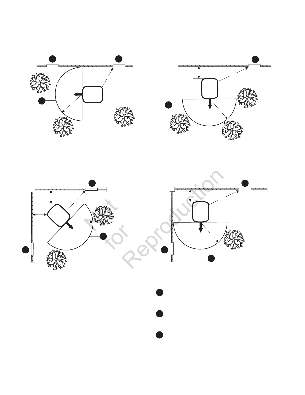
Single Structure Installations
Not
for
Reproduction
A A
Exhaust
Direction
B
Two Structure Installations
18 in (45.7 cm) min
5 ft (1.5 m)
Structure
5 ft (1.5 m) min
Structure
5 ft (1.5 m) min
Standby
A
Shrubs, Tree or
Vegitation
18 in (45.7 cm) min
B
18 in (45.7 cm) min
Standby
Exhaust
Direction
Structure
5 ft (1.5 m) min
5 ft (1.5 m)
Structure
5 ft (1.5 m) min
A
A
Standby
A
Exhaust
Direction
5 ft
(1.5 m)
Standby
Exhaust
B
A
Legend for Generator Locations to reduce the risk of fire.
Standby weatherproof enclosure must be at least 5 ft
A
Exhaust outlet side of weatherproof enclosure must
B
Standby weatherproof enclosure must have a
C
NOTICE DO NOT place weatherproof enclosure under a deck
or other type of covered structure that may confine airflow.
Direction
(1.5 m) from windows, doors, any wall opening, shrubs
or vegetation over 12 inches (30.5 cm) in height.
have at least 5 ft (1.5 m) minimum clearance from any
structure, shrubs, trees or any kind of vegetation.
minimum of 4 feet (1.2 m) overhead clearance from
any structure, overhang or trees.
5 ft (1.5 m)
B
13
Page 14

Other General Location Guidelines
Not
for
Reproduction
• Place the standby generator in a prepared location
that is flat and has provisions for water drainage.
• Install the standby generator in a location where
sump pump discharge, rain gutter down spouts, roof
run-off, landscape irrigation, or water sprinklers will
not flood the unit or spray the enclosure and enter
any air inlet or outlet openings.
• Install the standby generator where it will not affect or
obstruct any services (including covered, concealed
and underground), such as telephone, electric, fuel
(natural gas / LPG vapor), irrigation, air conditioning,
cable, septic, sewer, well and so forth.
• Install the standby generator where leaves, grass,
snow, etc will not obstruct air inlet and outlet
openings. If prevailing winds will cause blowing or
drifting, you may need to construct a windbreak to
protect the unit.
National Fire Protection Association (NFPA) Standard NFPA 37 Requirements and Testing
Requirements:
NFPA 37 2010, section 4. 1. 4, Engines Located Outdoors.
Engines, and their weatherproof housings if provided, that
are installed outdoors shall be located at least 1.5m (5 ft)
from openings in walls and at least 1.5 m (5 ft) from structures
having combustible walls. A minimum separation shall not be
required where either of the following conditions exist:
1. The adjacent wall of the structure has a fire resistance
rating of at least 1 hour.
2. The weatherproof enclosure is constructed
of noncombustible materials and it has been
demonstrated that a fire within the enclosure will not
ignite combustible materials outside the enclosure. *
* Annex A Explanatory Material
A.4.1.4 (2) Means of demonstrating compliance are by means
of full-scale fire tests or by calculation procedures, such as
those given in NFPA 555, Guide on Methods for Evaluating
Potential for Room Flashover.
To comply with condition 2 above the weatherproof
enclosure has been constructed completely of noncombustible materials and full-scale fire tests have been
conducted to demonstrate that a fire within the enclosure
will not ignite combustible materials outside the enclosure.
A U.S. Department of Labor Occupational Safety & Health
Administration (OSHA) Nationally Recognized Testing
Laboratory (NRTL) performed full scale fire demonstration
testing. This 3rd party independent NRTL evaluated
many worst-case ignition scenarios. The results of the
demonstration testing concluded that a fire within the
enclosure would not ignite combustible materials outside the
enclosure.
14
Page 15
Electrical and Fuel Inlet Locations
Not
for
Reproduction
The 3/4 inch N.P.T. fuel inlet connector
location
The home generator is shipped alr
mounting pad. Unless mandated by local code, a concrete
slab is not required.
B
is shown at right.
A
and electrical inlet
eady attached to its
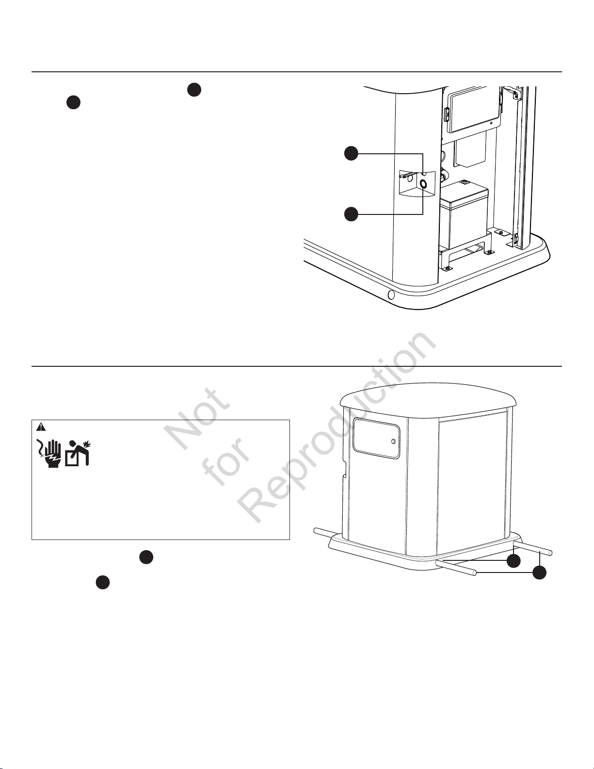
Lifting the Generator
B
A
The generator weighs more than 240 kg (530 pounds). Proper
tools, equipment and qualified personnel should be used in
all phases of handling and moving the generator.
WARNING Hazardous Voltage - Contact with power lines could
cause electric shock or burn, resulting in death or
serious injury.
Lifting Hazard / Heavy Object - Could result in
serious injury.
• If lifting or hoisting equipment is used, DO NOT contact any
power lines.
• DO NOT lift or move generator without assistance.
• Use lifting pipes as described in Lifting the Generator.
• DO NOT lift unit by roof as damage to generator will occur.
Two 48” lengths of 1” pipe
required to lift the generator manually. Insert pipes through
the lifting holes D located near the unit’s base.
You may also lift the unit using a “hook and hoist” method
attached to the lifting pipes, provided that you use a
spreader bar to ensure that the chains or cables DO NOT
touch the generator’s roof.
C
, supplied by the installer, are
D
C
After unit is in place, fill the lifting holes with the supplied
lifting hole plugs.
15
Page 16
Access Ports
Not
for
Reproduction
Each home generator is suppied with a set of identical keys.
These keys fit the lock that secures the control panel access
door.
To open access door:
1. Insert key into lock of access door and turn key one
quarter turn counterclockwise.
2. Remove key.
To close access door:
1. Close control panel door and insert key into lock and
turn key one quarter turn clockwise.
2. Remove key.
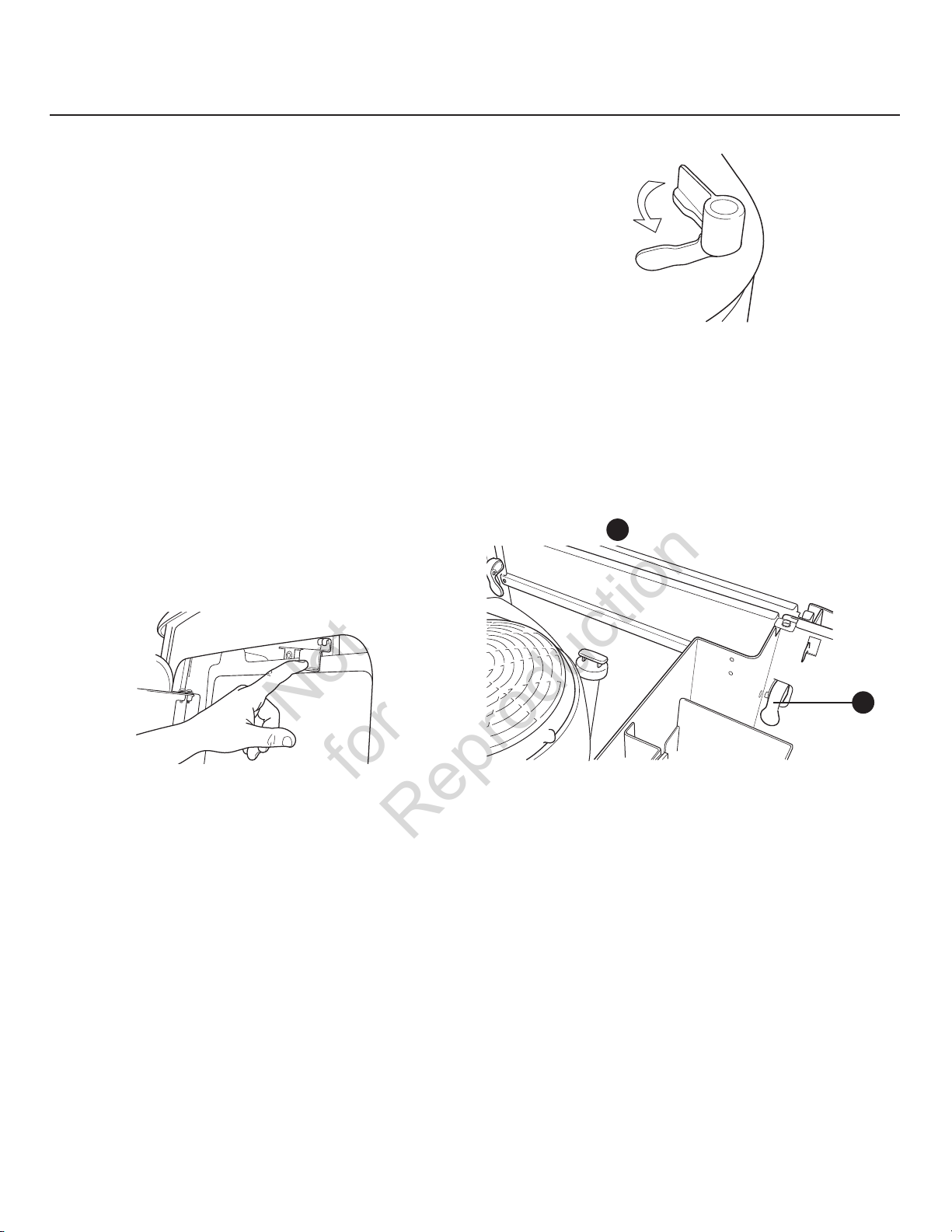
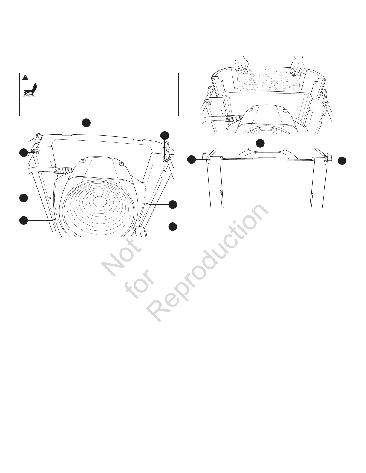
The home generator is equipped with a removable roof and
removable side panels to permit simple servicing.
To remove roof and divider:
1. Open the control panel access door.
2. Set generator’s circuit breaker to OFF position.
3. Set control panel system switch to OFF.
4. Remove 15 Amp fuse from control panel.
5. Move roof latch to the left until roof pops up slightly.
7. Rotate 4 knobs 1/4 turn and lift divider off.
8. Replace divider and roof in reverse order.
To remove side panels:
1. Open the control panel access door.
2. Set generator’s circuit breaker to OFF position.
3. Set control panel system switch to OFF.
4. Remove 15 Amp fuse from control panel.
5. Remove roof and divider.
6. Lift latches
A
up on both sides of panel to release.
6. Lift roof off of generator.
A
7. Pull panel upward and out of grooves.
16
Page 17
To remove exhaust panel:
Not
for
Reproduction
1. Remove roof and divider.
2. Remove side panels.
WARNING Contact with muffler area could cause burns
resulting in serious injury.
• DO NOT touch hot parts and AVOID hot exhaust gases.
• Allow equipment to cool before touching.
4. Pull exhaust panel up and out of base.
3. Remove 6 screws
A
A
A
A
from exhaust panel.
A
5. Remove two screws
B
A
6. Replace muffler cover and exhaust panel in reverse order.
A
To install side panels:
1. Place panel in grooves and slide down in place.
2. Push latches down on both sides of panel to lock into place.
3. Replace divider and roof.
and pull muffler cover off.
B
B
17
Page 18
The Gaseous Fuel System
Not
for
Reproduction
The information below is provided to assist gaseous fuel
system technicians in planning installations. In no way
should this information be interpreted to conflict with
applicable fuel gas codes. Consult with your local fuel
supplier or Fire Marshall if questions or problems arise.
WARNING Propane and Natural Gas are extremely flammable
and explosive, which could cause burns, fire or
explosion resulting in death, serious injury and/or
property damage.
• LP gas is heavier than air and will settle in low areas.
• Natural gas is lighter than air and will collect in high areas.
• The slightest spark could ignite these fuels and cause an explosion.
• DO NOT light a cigarette or smoke.
TO THE INSTALLER: Consult with the generator owner(s) and
convey any technical considerations that might affect their
installation plans before applying these general guidelines.
The following general rules apply to gaseous fuel
system piping:
WARNING Propane and Natural Gas are extremely flammable
and explosive, which could cause burns, fire or
explosion resulting in death, serious injury and/or
property damage.
• Before placing the generator into service, the fuel system lines
must be properly purged and leak tested.
• No leakage is permitted.
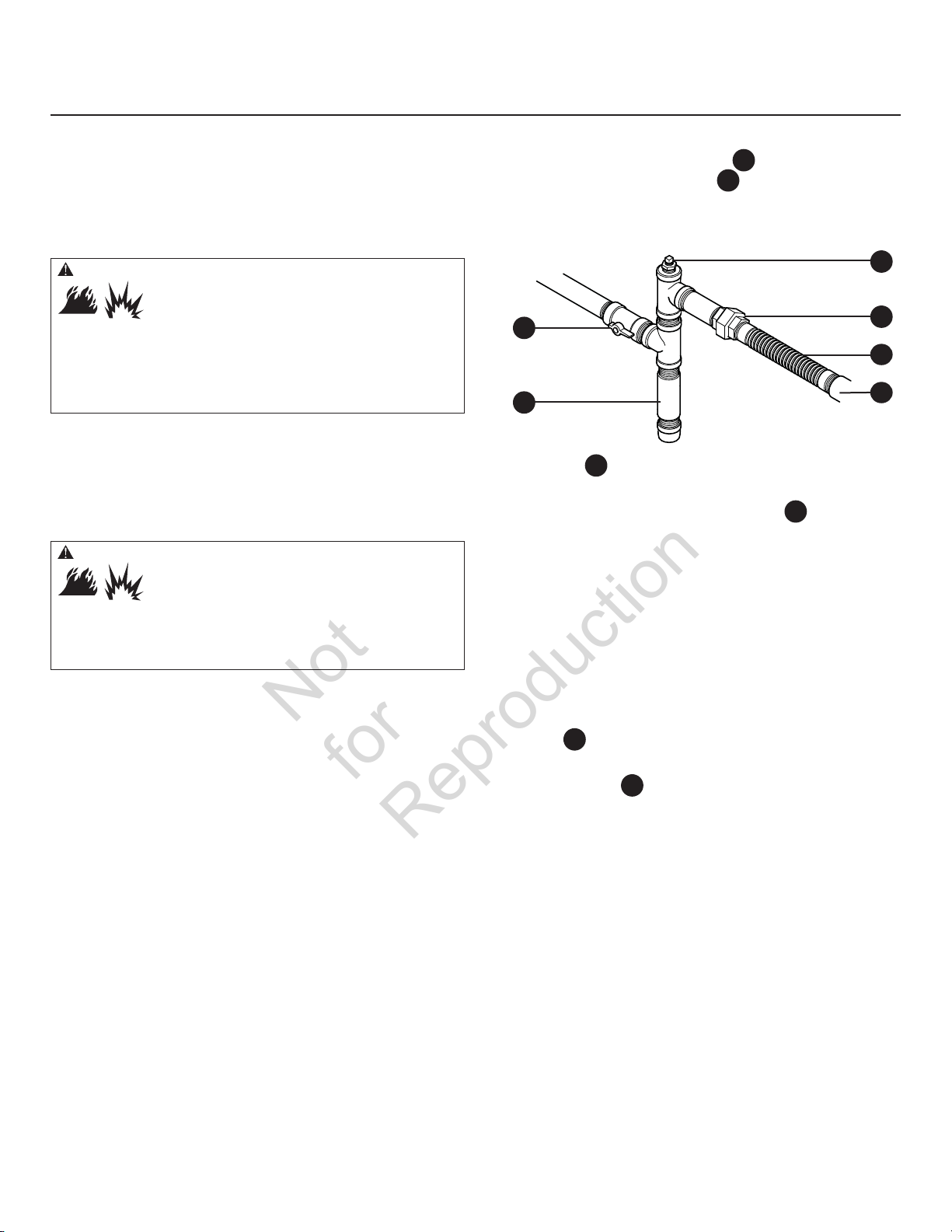
NOTICE The supplied flexible
underground or in contact with the ground.
• The entire
periodic inspection and must not be concealed within
nor contact nor run through any wall, floor, or partition.
• The piping should be of a material that conforms
to federal and local codes, rigidly mounted and
protected against vibration.
• Piping should be protected from physical damage
where it passes through flower beds, shrub beds, and
other cultivated areas where damage could occur.
flexible
steel fuel line
steel fuel line must be visible for
is not to be installed
• Install the
the generator fuel inlet port A and rigid piping
to prevent thermal expansion or contraction from
causing excessive stress on the piping material.
E
F
• A union C or flanged connection shall be provided
downstream to permit removal of controls.
• A manometer port should be provided D. A digital
manometer, P/N 19495, is available at your Briggs &
Stratton service center. When the initial test runs are
completed, the manometer is removed and the port
is plugged. The manometer port permits temporary
installation of a manometer to ensure that the
engine receives the correct fuel pressure to operate
efficiently throughout its operating range.
• Where the formation of hydrates or ice is known to
occur, piping should be protected against freezing. The
termination of hard piping should include a sediment
trap F where condensate is not likely to freeze.
• A minimum of one accessible, approved manual
shutoff valve E shall be installed in the fuel supply
line within 6 ft (180 cm) of the home generator.
• A minimum 10 ft. (3 m) section of gas pipe between
the primary fuel regulator and the generator fuel inlet
connection (acts as accumulator for high block loads).
• A manual fuel shut-off valve located in the interior of
the building.
• Where local conditions include earthquake,
tornado, unstable ground, or flood hazards, special
consideration shall be given to increase strength and
flexibility of piping supports and connections.
flexible
steel fuel line B (supplied) between
D
C
B
A
18
Page 19

• Piping must be of the correct size to maintain the
Not
for
Reproduction
r
equired supply pressures and volume flow under
varying generator load conditions with all gas
appliances connected to the fuel system turned on
and operating.
• Use a pipe sealant or joint compound approved for
use with NG/LPG on all threaded fittings to reduce the
possibility of leakage.
• Installed piping must be properly purged and
leak tested, in accordance with applicable codes
and standards.
Fuel Pressure
Both LP vapor and natural gas fuel supply pressure at the
generator’s fuel inlet port should be between the following levels
at full load with all gas appliances turned on and operating.
• NG is 5-7” W.C.
• LP is 11-14” W.C.
Ensur
e that all gas line shutoff valves are OPEN and that
adequate fuel pressure is available whenever automatic
operation is desired.
Power Loss
Air density is less at high altitudes, resulting in less available
engine power. Specifically, engine power will decrease 3.5%
for each 1,000 feet (300 m) above sea level and 1% for each
10° F (5.6°C) above 77°F (25°C). Generators located in these
conditions must have their transfer switch programmed
appropriately for this power decrease.
Fuel Pipe Sizing
There are numerous on-line or otherwise-published
references for fuel pipe sizing. For example, NFPA 54 National Fuel Gas Code, 2006 (Item #: 320-6031-06) is a
common resource.
The installer should consider the specific gravity of gas
and compensate for a nominal amount of restriction from
bends, fittings, etc. If an unusual number of fittings, bends, or
other restrictions are used, refer to federal and local codes
for guidance.
19
Page 20
Fuel Conversion
Not
for
Reproduction
The engine of your home generator system is factory
calibrated to run on natural gas (NG). It may also be operated
on liquefied petroleum (LP) vapor. The LP Conversion Kit
(supplied) is required to convert the unit to LP vapor fuel.
LP fuel inlet pressure must be between 11 and 14 inches
water column at full load with all gas appliances turned on
and operating.
To configure the fuel system for LP use:
1. Set generator’s system switch to OFF.
2. Remove 15 Amp fuse from control panel.
3. Remove roof, divider, side panels, exhaust panel and
muffler cover.
4. Change main jet in fuel mixer following instructions
provided in LP Conversion Kit.
5. Reinstall muffler cover, exhaust panel, side panels,
divider and roof.
6. Reinstall 15 Amp fuse in control panel.
7. Set generator’s system switch to AUTO.
The system is now ready to operate automatically using
LP vapor fuel.
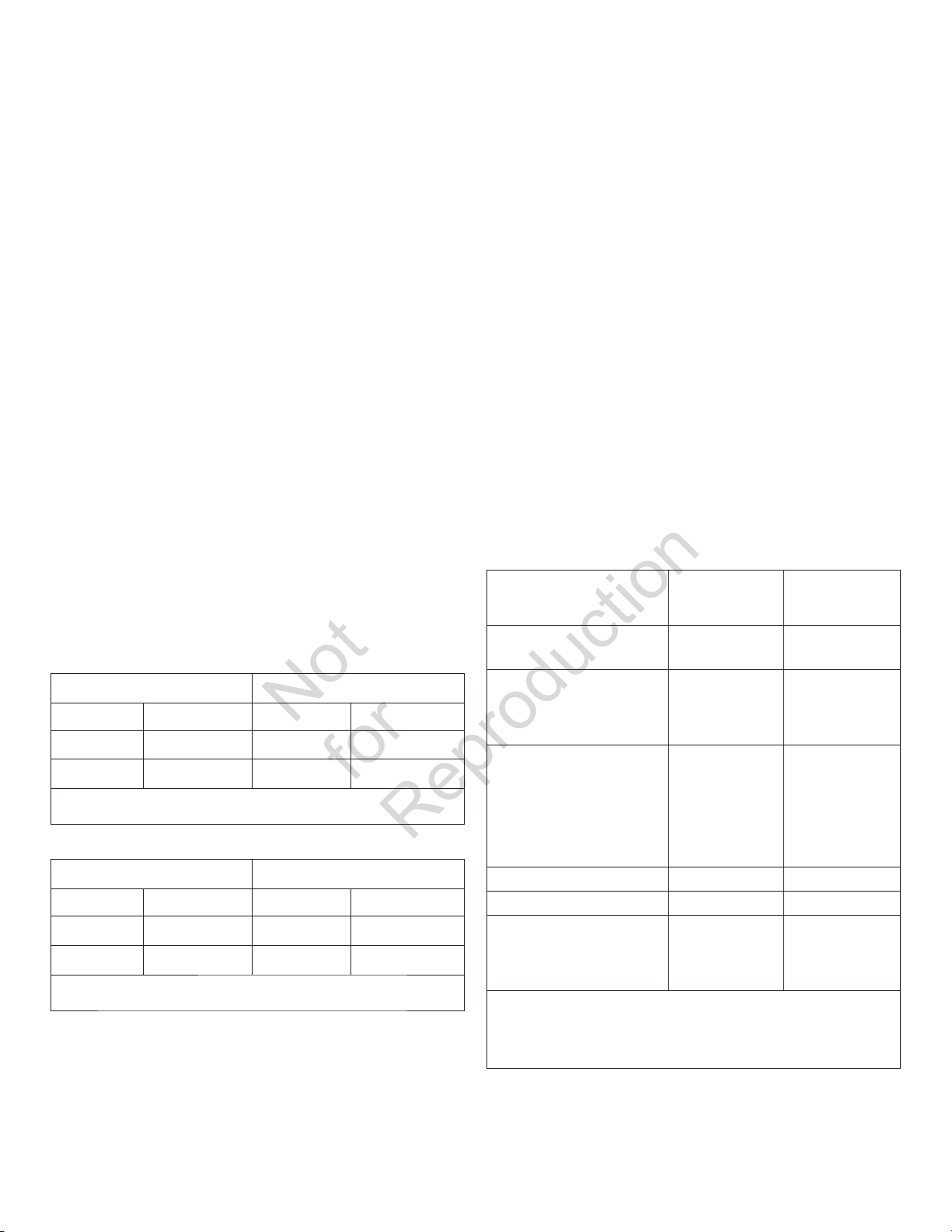
Fuel Consumption
Estimated fuel supply requirements at half and full load for
natural gas and LP vapor fuels are shown here.
11K Watt
Natural Gas LP Vapor
1/2 Load Full Load 1/2 Load Full Load
82 C 143 C 44 C 73 C
82,000 B 143,000 B 108,350 B 181,200 B
C = Cubic feet per hour
B = BTU’s per hour
13K Watt
Natural Gas LP Vapor
1/2 Load Full Load 1/2 Load Full Load
93 C 164 C 49 C 83 C
93,000 B 164,400 B 121,600 B 207,699 B
C = Cubic feet per hour
B = BTU’s per hour
Physical
Properties
Normal Atmospheric
State
Boiling Point (in °F):
Initial
End
Heating Value:
BTU per gallon (Net
LHV*)
BTU per gallon (gross**)
Cubic feet (gas)
Density*** 36.39 57.75
Weight† 4.24 2.65
Octane Number:
Research
Motor
* LHV (Low Heat Value) is the more realistic rating.
** Gross heat value does not consider heat lost in the form of water during
combustion.
*** Density is given in “Cubic Feet of Gas per Gallon of Liquid”.
† Weight is given in “Pounds per Gallon of Liquid”.
LP Vapor Natural
Gas
Gas Gas
-44
-44
83,340
91,547
2,500
110+
97
-259
-259
63,310
1,000
110+
20
Page 21
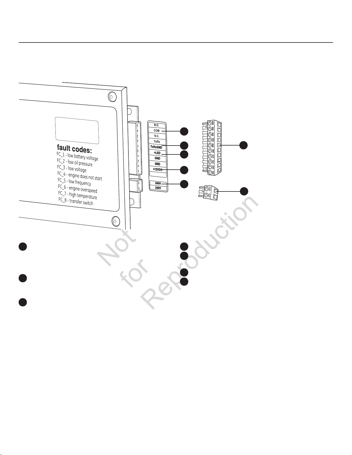
System Connectors
Not
for
Reproduction
Low Voltage connections to signal fault contacts, transfer switch communication, remote LED and auxiliary 12VDC power are
made via a removable ten-pin connector plug. Compare this illustration with your generator to familiarize yourself with the
location of these connections. Count down to the proper pin location on the control board since visual alignment with the decal
can be misleading:
A
A
- Fault Contacts ― Use NO, COM and NC to hook up a
siren, light, etc. to alert you in case of a fault. Contacts
reverse state (NO goes to NC and vice versa) upon a
fault condition.
B
- Transfer Switch Communication ― Connect to transfer
switch control board for communication interface using
18AWG copper twisted pair wire.
C
– LED ― Not Used.
B
C
D
E
D
- +12 Volt DC, .5 Amp Output ― Internal power supply.
E
- 240 Volt Utility ― Use to hook up the 240V utility leads
from the transfer switch to the generator.
F
– Ten-pin Connector Plug
G
– Two-pin Connector Plug
F
G
• For power output connection, use #6 AWG minimum 300 volt 90°C copper wire, (ref. NEC Table 310.16, 100 ft.
Use National Electric Code for correction factors and wire size calculations).
• For utility circuit connection use #14 AWG minimum 300 volt 90°C copper wire.
• For transfer switch communication use #18 AWG twisted pair conductors, no greater than 200 ft in length, 300 volt 90°C
copper wire.
• When connecting to the connector plugs, fasten only one wire to each connector screw.
• Torque connector plug screws to 7 in-lb (7.9 Newton meter).
21
Page 22

Generator AC Connection System
Not
for
Reproduction
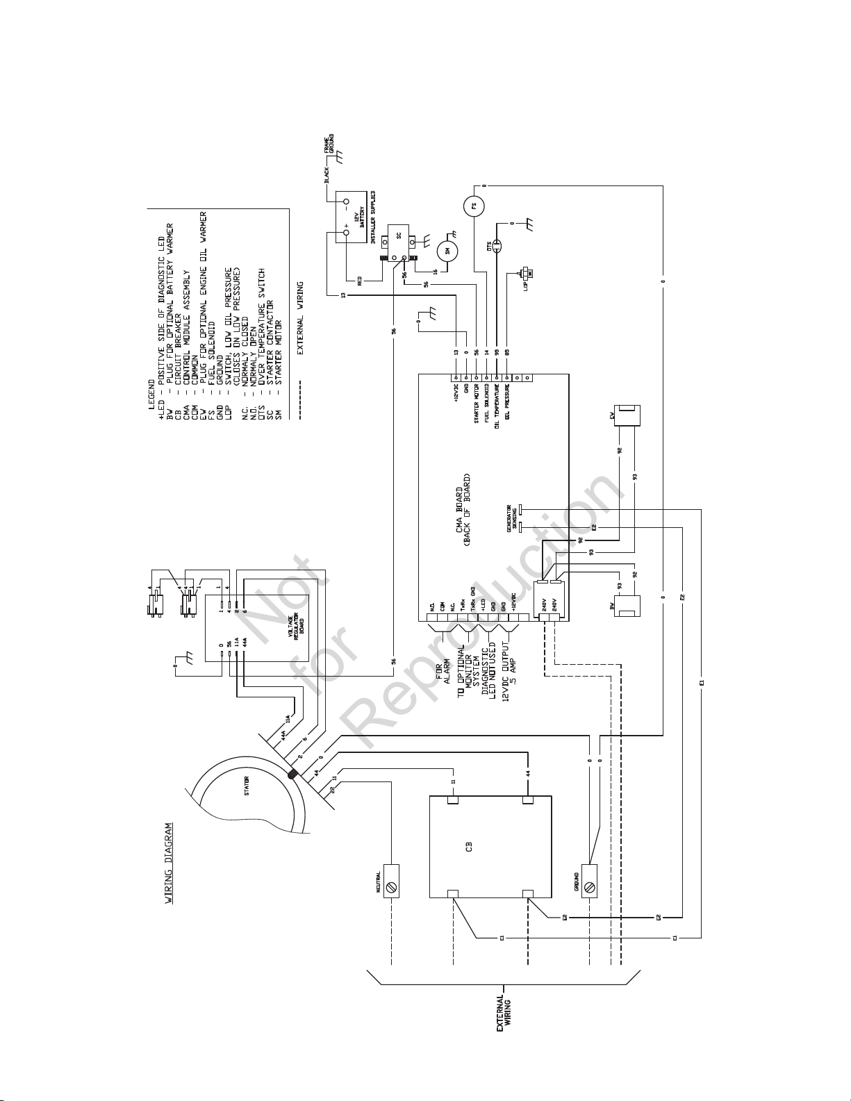
A single-phase, three-wire AC connection system is used in
the home generator. The stator assembly consists of a pair
of stationary windings with two leads brought out of each
winding. The junction of leads 22 and 33 forms the neutral
lead, as shown schematically and as a wiring diagram. A
complete schematic and wiring diagram can be found later
in this manual.
NOTICE
Neutral is not bonded to ground at generator.
The conduit
control panel is a UL requirement. If removed, it must be
replaced with similar conduit.
A
A
between the corner electrical inlet and the
Power Winding
33
44
Neutral
22
120V
120V
Circuit
Breaker
11
240V
1122 33 440
Grounding the Generator
Ground the home generator per applicable codes, standards,
and regulations. The generator GND lug is located inside the
control panel box.
Neutral
Circuit
Breaker
Line 2Ground
To Transfer Switch
Line 1
22
Page 23
Utility Circuit Connection
Not
for
Reproduction
“240V Utility” leads must be routed in conduit. The “240V
Utility” leads deliver power to the generator’s circuit board,
optional battery warmer and optional oil warmer. This power
also charges the battery. When power on these leads is lost,
the generator will start.
Using provided 2 pin connector plug and installer-supplied
minimum 300V, 14 AWG copper wire, connect each control
circuit terminal in the generator to the two-amp fuse
terminals in the automatic transfer switch.
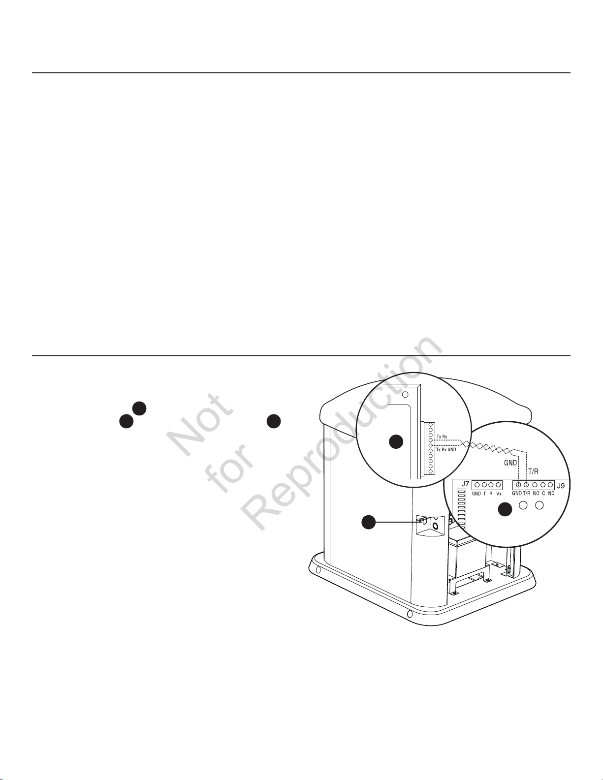
Transfer Switch Communication
(Units with ACCM II or later transfer switch only)
Using #18 AWG twisted pair conductors, no greater than
200 ft in length, connect Tx Rx and Tx Rx GND from the
generator control panel
switch control board B via the low voltage access hole C.
A
to T/R and GND on the transfer
When making connections, obey wire type and torque
specifications printed on the circuit breaker and neutral/
ground connector.
A
B
C
23
Page 24
Fault Detection System
Not
for
Reproduction
The generator may have to run for long periods of time with
no operator present. For that reason, the system is equipped
with sensors that automatically shut down the generator
in the event of potentially damaging conditions, such as
low oil pressure, high temperature, over speed, and other
conditions. Refer to Fault Detection System in the operator’s
manual for more detailed information.
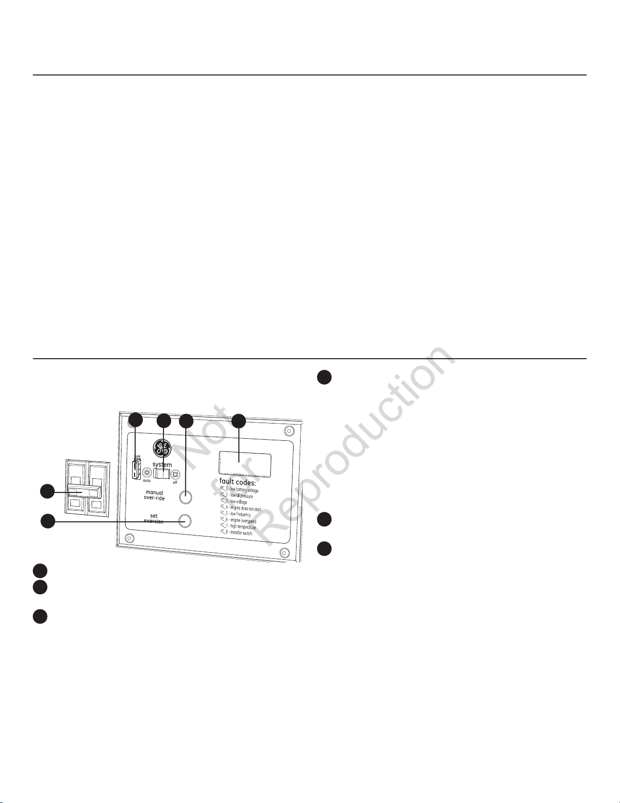
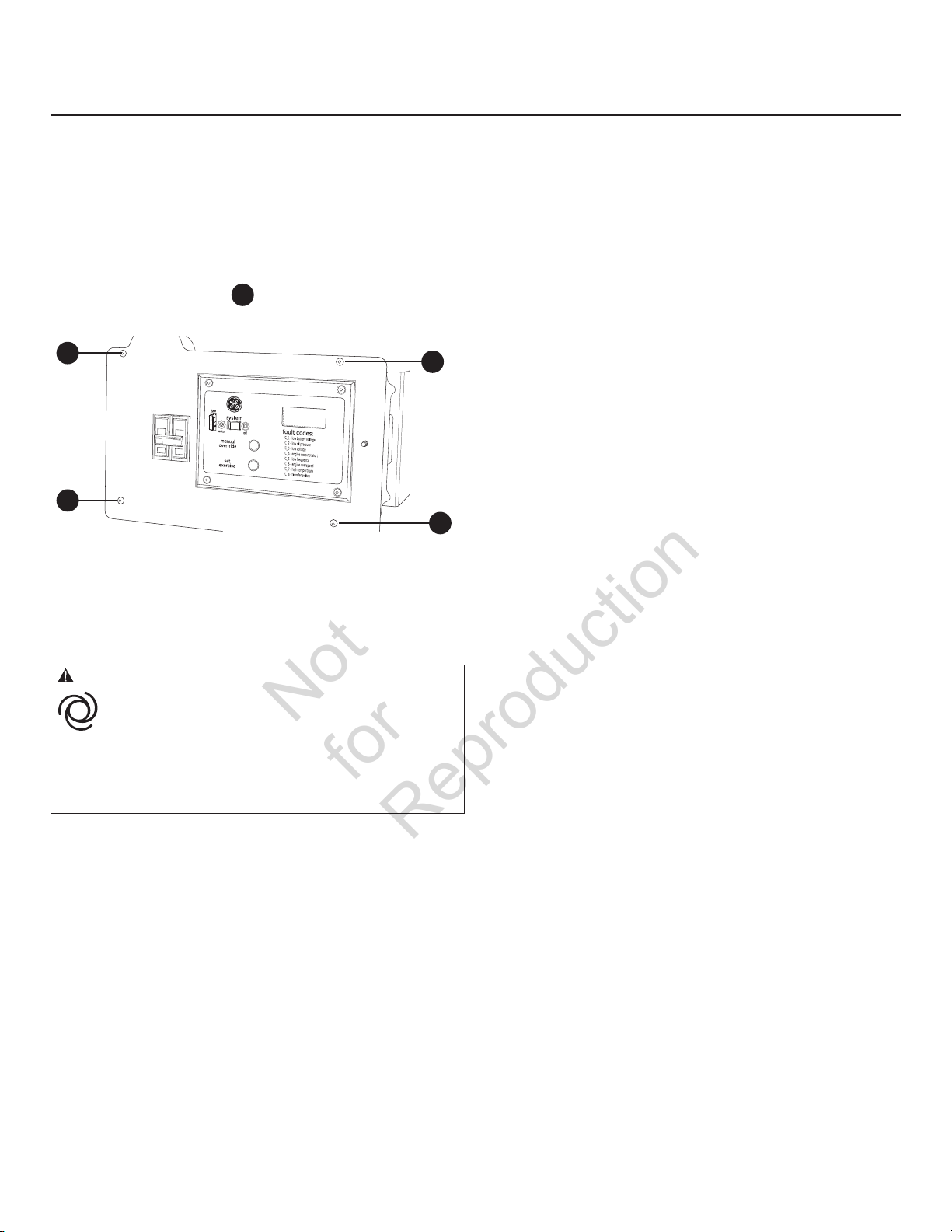
System Control Panel
The home generator control panel, located inside the
generator housing, is shown below. Brief descriptions of the
controls used during installation are:
C
D
E F
B
A
A
- Set Exercise ― Used to set the exercise cycle.
B
- Circuit Breaker ― Must be ON to supply power to the
transfer switch.
C
- 15 Amp Fuse ― Protects the home generator DC
control circuits. If the fuse has ‘blown’ (melted open) or
was removed, the engine cannot crank or start. Replace
the fuse using only an identical ATO 15A fuse. One
spare fuse is supplied with the unit. If fuse was blown or
removed, you will need to reset the exercise timer (see
Setting Exercise Timer).
D
- System Switch ― This two-position switch is the most
important control on the home generator and is used as
follows:
•“AUTO” position is the normal operating position. If a
utility power outage is sensed, the system will start the
generator. When utility power is restored, lets the engine
stabilize internal temperatures, shuts off the generator,
and waits for the next utility power outage.
•“OFF” position turns off running generator, prevents unit
from starting and resets any detected faults.
E
– MANUAL OVER-RIDE ― Used to manually start and
stop the generator.
F
- Digital Display ― Displays running time in hours or
fault codes.
e information may be found in Controls in the
Mor
operator’s manual.
24
Page 25
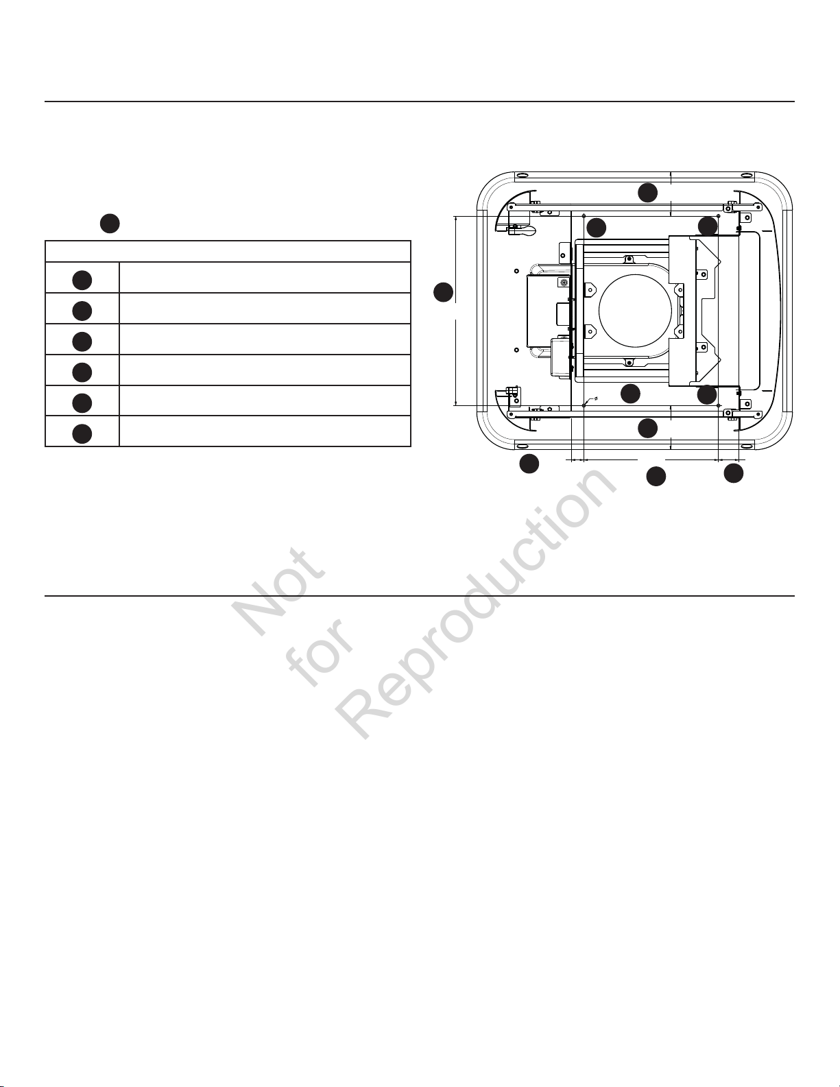
Concrete Slab (Optional)
Not
for
Reproduction
If mandated by local code, construct a concrete slab at least
3 in (76 mm) thick and 6 in (152 mm) longer and wider than
the unit (34.6 in (880 mm) x 39.4 in (1000 mm)). Attach unit to
slab with 1/4” (6 mm) diameter (minimum) masonry anchor
bolts long enough to retain the unit.
Drill anchor bolt holes into the unit base at the four ideal
locations
Anchor Bolt Drill Location Measurements
F
indicated.
5.51 in
140
A
(140mm)
F
F
A
B
C
D
E
F
5.51 in (140 mm)
23.62 in (600 mm)
16.78 in (426.4 mm)
2.55 in (65 mm)
1.57 in (40 mm)
1/4 in (6 mm) holes
Gravel Base (Optional)
If mandated by local code, clear an area approximately five
inches deep and about six inches wider that the foot print
of the standby generator. Line the area with polyurethane
film and fill with pea gravel or crushed stone. Compact and
level the stone. If concrete slab is required, see Concrete Slab
section in this manual.
B
23.62 in
(600mm)
1/4 in
F
(6mm)
5.51 in
A
(140mm)
1.57 in
40
(40mm)
E
16.78 in
426.4
(426.4mm)
C
F
140
2.55 in
(65mm)
D
25
Page 26
Final Installation Considerations
Not
for
Reproduction
Engine Oil
NOTICE Any attempt to crank or start the engine before it has
been properly serviced with the recommended oil will result in
equipment failure.
• Refer to Maintenance in the operator’s manual for oil fill
information.
• Damage to equipment resulting from failure to follow this
instruction will void engine and generator warranty.
This engine is shipped from the factory pre-run and filled
with synthetic oil (API SJ/CF 5W-30). This allows for system
operation in a wide range of temperature and climate
conditions. Before starting the engine, check oil level as
described in Maintenance of the Operator’s Manual.
The use of synthetic oil does not alter the required oil change
intervals described in the Operator’s Manual.
Battery
The installer must supply and install a valve-regulated
rechargeable 12 volt starting battery. The starting battery
MUST conform to the specifications shown in this chart.
Battery Specifications
Volts 12 Volt DC
Amps (MIN) 600 CCA (cold cranking amps)
Type AGM (absorbent glass mat)
Terminal Hardware M6
Dimensions (MAX):
Width 5.5 inches (140 mm)
Length 9.0 inches (230 mm)
Height 8.25 inches (210 mm)
Install the battery as described in Servicing the Battery in
the Maintenance section of the operator’s manual. Always
make sure the NEGATIVE cable is connected last and that
the red POSITIVE terminal insulator is fully in place.
WARNING Battery posts, terminals and related accessories
contain lead and lead compounds, chemicals known to the State
of California to cause cancer and reproductive harm. Wash hands
after handling.
WARNING Storage batteries give off explosive hydrogen gas
during recharging.
Slightest spark will ignite hydrogen and
cause explosion, resulting in death, serious
injury and/or property damage.
Battery electrolyte fluid contains acid and is extremely caustic.
Contact with battery contents could cause severe chemical burns.
A battery presents a risk of electrical shock and high short
circuit current.
• DO NOT dispose of battery in a fire. Recycle battery.
• DO NOT allow any open flame, spark, heat, or lit cigarette during
and for several minutes after charging a battery.
• DO NOT open or mutilate the battery.
• Wear protective goggles, rubber apron, rubber boots and
rubber gloves.
• Remove watches, rings, or other metal objects.
• Use tools having insulated handles.
26
Page 27
Initial Start-up (No Load)
Not
for
Reproduction
Unit has been set-up for NG operation at the factory. Fuel
conversion, if needed, must be completed prior to performing
these steps. See Fuel Conversion.
Before operating the home generator or placing it into
service, inspect the entire installation carefully. Then begin
testing the system without any electrical loads connected,
as follows:
1. Remove four screws
to enclosure to expose unit’s circuit breaker.
A
A
2. Connect an accurate frequency meter to line side of
generator’s main circuit breaker.
3. Set generator’s main circuit breaker to ON
(closed) position.
4. Set generator’s system switch to OFF.
CAUTION Installing the 15A fuse could cause the engine
to start at any time without warning resulting in minor or
moderate injury.
A
that secure control box front
A
A
When the generator is started for the very first time, it will
require that air in the gaseous fuel lines be purged. This may
take a few minutes.
8. Listen for unusual noises, vibration or other
indications of abnormal operation. Check for oil leaks
while engine runs.
9. Let engine warm up for about five minutes to allow
internal temperatures to stabilize.
10. Check generator output at load side of circuit breaker.
Voltage should be 239 - 262 Volts, frequency should
be 62.0 - 62.5 Hz.
If either parameter is outside these ranges, perform Engine
Adjustment described later in this section.
11. Check generator output between one generator
connection lug and neutral lug, then between
other generator connection lug and neutral lug.
In both cases, voltage reading should be between
119 and 131 Volts.
DO NOT proceed until you are certain that generator AC
voltage and frequency are correct and within the stated
limits. To obtain the proper generator frequency, see
Engine Adjustment.
12. Push and hold MANUAL OVER-RIDE button on control
panel until engine stops.
13. Reinstall control panel into enclosure.
• Observe that the 15 Amp fuse has been removed from the control
panel for shipping.
• DO NOT install this fuse until all plumbing and wiring has been
completed and inspected.
5. Install 15 Amp fuse in control panel.
6. Set generator’s system switch to AUTO.
7. Push and hold MANUAL OVER-RIDE button on control
panel for about six seconds. Engine will start.
27
Page 28
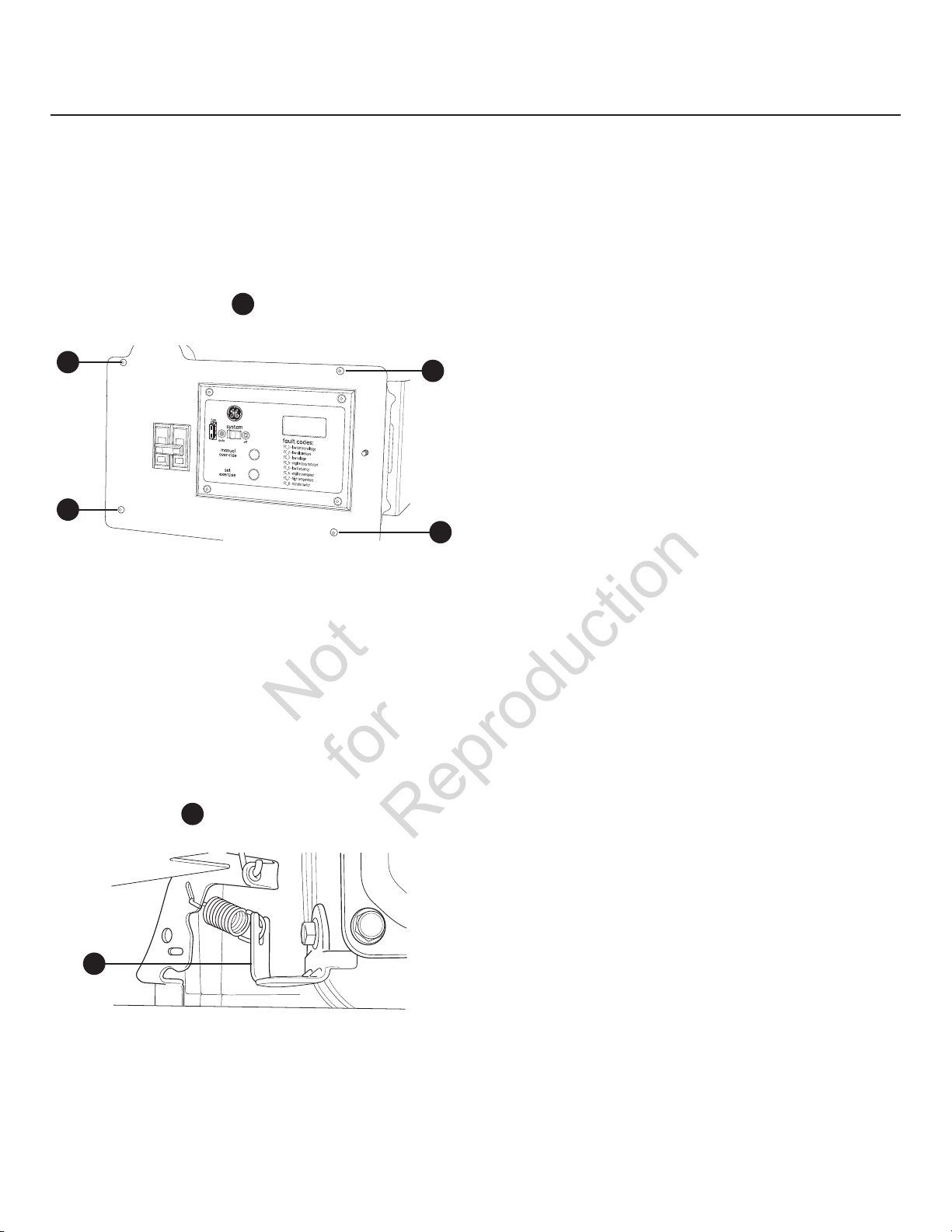
Engine Adjustment
Not
for
Reproduction
There are regional variances in the composition of natural
gas. Each home generator unit leaves the factory set for
NG operation. If the generator output voltage or frequency
measured during Initial Start-Up is outside the listed ranges,
the combustibility of the gas supplied at the installation
site may be substantially different from the fuel used at
the factory.
To adjust the engine for this difference, proceed as follows:
1. Remove four screws
to enclosure to expose unit’s circuit breaker.
A
A
2. Connect an accurate frequency meter to line side of
generator’s main circuit breaker.
3. Ensure that the 15 Amp fuse is installed.
4. Set the generator’s main circuit breaker ON.
5. Set the generator’s system switch to AUTO.
6. Push MANUAL OVER-RIDE button on control panel.
When the engine starts, allow it to warm up for
five minutes.
7. Normal no load frequency is 62.0 to 62.5 Hz. If
adjustment is needed at no load, remove unit
side panels. Using needle nose pliers, bend spring
anchor tang B slowly up or down until frequency is
62.0 to 62.5 Hz.
A
that secure control box front
A
8. Turn utility service disconnect to transfer switch OFF.
After a short time delay, transfer switch will connect
to generator.
9. Load generator to full load.
10. After load stabilizes, frequency should be
above 57.0 Hz.
11. If frequency is below 57.0 Hz, slowly adjust the
governor until frequency is above 57.0 Hz.
12. Turn service disconnect to transfer switch ON.
Transfer switch will connect to utility power after
five minutes.
13. Push and hold MANUAL OVER-RIDE button on control
panel until engine stops.
14. After the engine has stopped:
• If an adjustment was made in step 11, repeat steps
2 through 7.
• If an adjustment was not made in step 11, proceed
A
If no load frequency falls out of the no load range shown
in step 7 after full load adjustment is made, contact an
authorized service center.
15. Reinstall control panel into enclosure.
to step 15.
B
28
Page 29

Not
for
Reproduction
29
Page 30
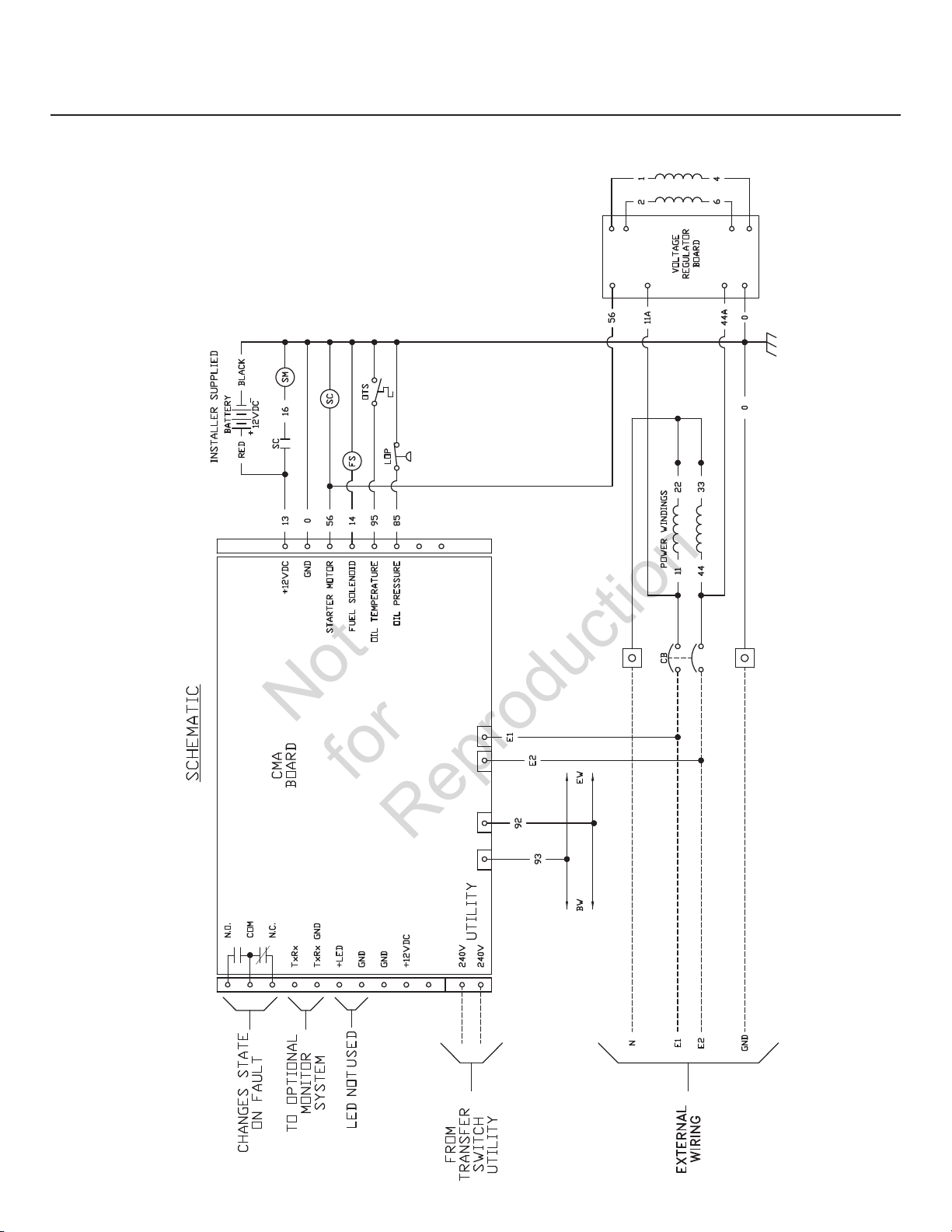
Schematic / Wiring Diagrams
Not
for
Reproduction
Schematic Diagram 11,000 Watt
30
Page 31

Wiring Diagram 11,000 Watt
Not
for
Reproduction
31
Page 32
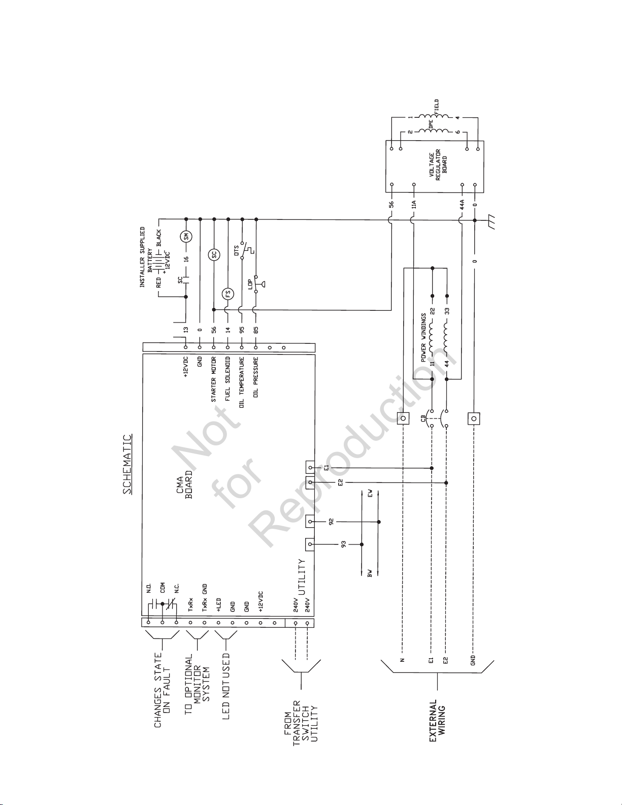
Schematic Diagram 13,000 Watt
Not
for
Reproduction
32
Page 33
Wiring Diagram 13,000 Watt
Not
for
Reproduction
33
Page 34

Operation
Not
for
Reproduction
Automatic Operation Sequence
The generator’s control panel houses a logic control circuit
board. This control board constantly monitors utility power
source voltage. Should that voltage drop below a preset
level, control board action will signal the engine to crank
and start.
When utility source voltage is restored above a preset
voltage level, the engine is signaled to shut down.
The actual system operation is not adjustable and is
sequenced by sensors and timers on the control board,
as follows:
Utility Voltage Dropout Sensor
• This sensor monitors utility source voltage.
• If utility source voltage drops below about 70 percent
of the nominal supply voltage, the sensor energizes
a 10 second timer. The timer is used to ‘sense’
brown-outs.
• Once the timer has expired, the engine will crank
and start.
Utility Voltage Pickup Sensor
This sensor monitors utility power supply voltage. When that
voltage is restored above 80 percent of the nominal source
voltage, a time delay starts timing and the engine will go to
engine cool-down.
Engine Cool-down Timer
• When the load is transferred back to the utility power
source, the engine cool-down timer starts timing.
• The timer will run for about one minute, then the
generator will stop.
• Minimum engine run time is 5 minutes.
34
Page 35

Setting Exercise Timer
Not
for
Reproduction
The home generator is equipped with an exercise timer that
will start and exercise the system once every seven days.
During this exercise period, the unit runs for approximately
20 minutes and then shuts down. Electrical load transfer
DOES NOT occur during the exercise cycle (unless an utility
power outage occurs).
A button on the control panel is labeled “SET EXERCISE” (see
System Control Panel). The specific day and the specific
time of day this button is pressed is programmed into the
control board memory. This date and time is then used to
automatically initiate the system exercise cycle. The “SET
EXERCISE” legend on the control panel will flash until the set
exercise cycle is set.
To perform the Set Exercise procedure:
1. Choose the day and time you want your home
generator to exercise.
2. On that day and time, press and hold “SET EXERCISE”
for three seconds.
The “Set Exercise” display will illuminate then turn off
to confirm that the exercise timer has been set. Then
release the button.
The unit will crank and run the exercise cycle. During
the cycle, “Set Exercise” will illuminate.
Once the exercise cycle is complete, the unit will turn
off and “Set Exercise” will no longer be displayed.
The exercise cycle may be discontinued at anytime by
turning the System Switch to OFF.
3. The unit will then start and run it’s 20 minute exercise
cycle.
For example, if you press SET EXERCISE on Sunday morning
at 10:00 AM, the unit will run an immediate exercise cycle
and an exercise cycle every following Sunday at 10:00 AM
(+/- 1/2 hour).
“Set Exercise” will only work if the unit is in the AUTO mode
and this exact procedure is followed. The exerciser will need
to be re-set if the 15 Amp fuse is removed or changed, or if
the starting battery is disconnected.
If you want to change the day and time the unit exercises,
simply perform the “Set Exercise” procedure at the exact
weekday and time you want it to take place.
Generator will not exercise if timer is not set.
35
Page 36

Installation Inspection
Not
for
Reproduction
Before placing the generator system into service, inspect the
entire installation carefully.
This completes the installation and start-up instructions.
The operator’s manual provides full details on Operation,
Maintenance and Troubleshooting for this generator system.
is a trademark of General Electric Company
and is under license by Briggs & Stratton
Power Products Group, LLC.
36
Copyright © 2011. All rights reserved. No part of this material may
be reproduced or transmitted in any form without the express
written permission of Briggs & Stratton Power Products Group, LLC.
Page 37

GE Home Generator Systems
Not
for
Reproduction
Sistema generador doméstico
Manual de instalación
y arranque
Page 38

Gracias por aduirir este generador doméstico de reserva GE de alta calidad. Nos complace ue haya depositado su
Not
for
Reproduction
confianza en la marca GE. Si se utiliza y mantiene conforme a las instrucciones de este manual, el generador GE le
ofrecerá muchos años de servicio fiable.
Este manual contiene información de seguridad para que usted conozca los peligros y riesgos propios de los sistemas
generadores domésticos y cómo evitarlos. Este sistema generador doméstico está diseñado y pensado para utilizarlo
únicamente como un sistema de reserva doméstico opcional que proporciona una fuente alternativa de energía
eléctrica con capacidad para alimentar cargas tales como sistemas de calefacción y refrigeración y sistemas de
comunicaciones, que cuando dejan de funcionar a causa de una interrupción de la alimentación eléctrica de la red
pueden producir incomodidades o problemas. Guarde estas instrucciones originales para futuras consultas.
Este generador de reserva doméstico debe ser instalado por un profesional antes de ser utilizado. El instalador
debe seguir las instrucciones por completo.
Dónde encontrarnos
No tiene que buscar mucho para obtener ayuda y servicio de mantenimiento para su generador. Consulte las Páginas
Amarillas. Existen muchos distribuidores de servicio autorizados de GE que brindan servicio de calidad. También
puede comunicarse por teléfono al número 888 575-8226. entre 08:00 a. m. y 5:00 p. m., hora del centro de los EE.
UU; o haga clic en SERVICE & SUPPORT en www.homestandbygeneratorsystems.com para que aparezca una lista de
distribuidores autorizados.
Para la referencia futura
Complete por favor la información abajo y guarde con su recibo para asistir a la identificación de la unidad para las
ediciones futuras de la compra.
Fecha de compra
Generador
Número de modelo
Revisión
Número de serie
Motor
Número de modelo
38
Page 39

Tabla de contenido
Not
for
Reproduction
Instrucciones de seguridad . . . . . . . . . . . . . . . . . . . . . . . . . . . . . . . . . . . . . 40
Instrucciones importantes de seguridad . . . . . . . . . . . . . . . . . . . . . . . . . . . . . . . . . . . . 40
Instalación. . . . . . . . . . . . . . . . . . . . . . . . . . . . . . . . . . . . . . . . . . . . . . . . . . . . 44
Responsabilidades del propietario. . . . . . . . . . . . . . . . . . . . . . . . . . . . . . . .
Responsabilidades del distribuidor/técnico instalador. . . . . . . . . . . . . . . . . . . . . . . . 44
Juego para climas fríos . . . . . . . . . . . . . . . . . . . . . . . . . . . . . . . . . . . . . . . . . . . . . . . . . . . 44
Precauciones al momento del desempaque . . . . . . . . . . . . . . . . . . . . . . . . . . . . . . . . . 45
Inspección al momento de la entrega. . . . . . . . . . . . . . . . . . . . . . . . . . . . . . . . . . . . . . . 45
Contenido de la caja . . . . . . . . . . . . . . . . . . . . . . . . . . . . . . . . . . . . . . . . . . . . . . . . . . . . . . 45
Lista de control de la instalación . . . . . . . . . . . . . . . . . . . . . . . . . . . . . . . . . . . . . . . . . . . 46
Colocación del generador . . . . . . . . . . . . . . . . . . . . . . . . . . . . . . . . . . . . . . . . . . . . . . . . . 46
Colocación de un generador de reserva para
reducir el riesgo de envenenamiento por monóxido de carbono . . . . . . . . . . . . . . 47
Colocación de un generador de reserva para reducir el riesgo de incendio . . . . . 49
OTRAS directrices generales de ubicación. . . . . . . . . . . . . . . . . . . . . . . . . . . . . . . . . . . 51
Requisitos y pruebas de la norma NFPA 37 de National Fire Protection Association (NFPA) 51
Ubicación de las entradas eléctricas y de combustible . . . . . . . . . . . . . . . . . . . . . . . 52
Elevación del generador. . . . . . . . . . . . . . . . . . . . . . . . . . . . . . . . . . . . . . . . . . . . . . . . . . . 52
Puertas de acceso . . . . . . . . . . . . . . . . . . . . . . . . . . . . . . . . . . . . . . . . . . . . . . . . . . . . . . . . 53
Sistema de combustible gaseoso. . . . . . . . . . . . . . . . . . . . . . . . . . . . . . . . . . . . . . . . . . . 55
44
Conversión de combustible . . . . . . . . . . . . . . . . . . . . . . . . . . . . . . . . . . . . . . . . . . . . . . . . 57
Consumo de combustible. . . . . . . . . . . . . . . . . . . . . . . . . . . . . . . . . . . . . . . . . . . . . . . . . . 57
Conexiones de sistema . . . . . . . . . . . . . . . . . . . . . . . . . . . . . . . . . . . . . . . . . . . . . . . . . . . . 58
Sistema de conexión de c.a. del generador . . . . . . . . . . . . . . . . . . . . . . . . . . . . . . . . . . 59
Conexión a tierra del generador. . . . . . . . . . . . . . . . . . . . . . . . . . . . . . . . . . . . . . . . . . . . 59
Interconexiones del circuito de control. . . . . . . . . . . . . . . . . . . . . . . . . . . . . . . . . . . . . . 60
Comunicación del conectador . . . . . . . . . . . . . . . . . . . . . . . . . . . . . . . . . . . . . . . . . . . . . 60
Sistema de detección de fallas . . . . . . . . . . . . . . . . . . . . . . . . . . . . . . . . . . . . . . . . . . . . . 61
Panel de control del sistema . . . . . . . . . . . . . . . . . . . . . . . . . . . . . . . . . . . . . . . . . . . . . . . 61
Solera de concreto (opcional) . . . . . . . . . . . . . . . . . . . . . . . . . . . . . . . . . . . . . . . . . . . . . . 62
Consideraciones finales para la instalación . . . . . . . . . . . . . . . . . . . . . . . . . . . . . . . . . 63
Arranque inicial (sin carga) . . . . . . . . . . . . . . . . . . . . . . . . . . . . . . . . . . . . . . . . . . . . . . . . 64
Ajuste del motor. . . . . . . . . . . . . . . . . . . . . . . . . . . . . . . . . . . . . . . . . . . . . . . . . . . . . . . . . . 65
Utilización . . . . . . . . . . . . . . . . . . . . . . . . . . . . . . . . . . . . . . . . . . . . . . . . . . . . 66
Secuencia de operación automática . . . . . . . . . . . . . . . . . . . . . . . . . . . . . . . . . . . . . . . . 66
Configuración del temporizador de práctica. . . . . . . . . . . . . . . . . . . . . . . . . . . . . . . . . 67
Inspección posterior a la instalación. . . . . . . . . . . . . . . . . . . . . . . . . . . . . . . . . . . . . . . . 68
39
Page 40

Instrucciones de seguridad
Not
for
Reproduction
Instrucciones importantes de seguridad
GUARDE ESTAS INSTRUCCIONES - Este manual contiene
instrucciones importantes que se deben seguir durante
la instalación y el mantenimiento del generador y de
las baterías.
Símbolos sobre la seguridad y significados
Explosión
Gases Tóxicos
Peligro al Elevar Lea el Manual
Fuego
Partes en Movimiento Superficie Caliente
Presión ExplosivaArranque Automático
Descarga Eléctrica
Quemaduras Química
El fabricante no puede prever todas las posibles
circunstancias que pueden implicar riesgos. Por lo tanto, las
advertencias que aparecen en este manual y las etiquetas
y calcomanías adheridas a la unidad no incluyen todas las
posibilidades. Si aplica un procedimiento, método de trabajo
o técnica de operación no recomendada específicamente
por el fabricante, debe estar seguro de que se trata de una
práctica segura para usted y para otras personas. También
debe asegurarse de que el procedimiento, método de trabajo
o técnica de operación que elija, no haga que el generador
se torne inseguro.
ADVERTENCIA Los motores en funcionamiento emiten
monóxido de carbono, un gas tóxico, inodoro e incoloro.
La inhalación de monóxido de carbono puede provocar
lesiones graves, dolor de cabeza, fatiga, mareos, vómitos,
confusión, convulsiones, náuseas, desmayos o incluso la muerte.
• Haga funcionar este producto ÚNICAMENTE a la intemperie en una
zona en donde no se acumulen gases de escape mortales.
• Evite que los gases de escape entren por ventanas, puertas, tomas
de aire de ventilación, ventilaciones en plafones, entresuelos, puertas
de garaje abiertas u otras aberturas que permitan que entre o se
arrastre dentro de un edificio o estructura que pueda estar habitado.
• Los detectores del monóxido de carbono deben ser instalados y
deben ser mantenidos dentro según las instrucciones del fabricante
recomendaciones. Los detectores de humo no pueden discernir gas
de monóxido de carbono.
El símbolo de alerta de seguridad indica un posible
riesgo para su integridad física. Se utiliza una palabra de
señalización (PELIGRO, ADVERTENCIA o ATENCIÓN) junto
con el símbolo de alerta para designar un grado o nivel
de gravedad de riesgo. Se puede utilizar un símbolo de
seguridad para representar el tipo de riesgo. La palabra de
señalización AVISO se utiliza para hacer referencia a una
práctica no relacionada con una lesión física.
PELIGRO indica un riesgo que, de no evitarse, provocará
la muerte o lesiones de gravedad.
ADVERTENCIA indica un riesgo que, de no evitarse, podría
provocar la muerte o lesiones de gravedad.
ATENCIÓN indica un riesgo que, de no evitarse, podría
provocar lesiones leves o moderadas.
AVISO hace referencia a una práctica no relacionada con
una lesión física.
40
ADVERTENCIA El escape del motor de este producto contiene
elementos químicos reconocidos en el Estado de California
por producir cáncer, defectos de nacimiento u otros daños de
tipo reproductivo.
ADVERTENCIA Determinados componentes en este producto
y los accesorios relacionados contienen sustancias químicas
declaradas cancerígenas, causantes de malformaciones, y otros
defectos congénitos por el Estado de California. Lávese las manos
después de manipular estos elementos.
Page 41
ADVERTENCIA
Not
for
Reproduction
El fluido de electrolito de la batería contiene ácido y es
extremadamente cáustico.
El contacto con el fluido de la batería puede causar quemaduras
químicas severas.
Las baterías presentan un riesgo de descarga eléctrica y de
elevada corriente de cortocircuito.
• NO deseche la batería tirándola al fuego. Recicle la batería.
• No permita ninguna llama abierta, chispa, calor, o encienda
un cigarrillo durante y por varios minutos después de haber
recargado la batería.
• NO abra ni manipule la batería.
• Utilice gafas de protección, y delantal, botas y guantes de goma.
• No lleve relojes, anillos ni otros objetos metálicos.
• Utilice herramientas con mangos aislados.
ADVERTENCIA El Gas Natural y el Propano son
• Instale el sistema de suministro de combustible de acuerdo con
los códigos de gas combustible que correspondan.
• Antes de poner en servicio el sistema de generador de doméstico,
se deben purgar las líneas del sistema de combustible y se debe
probar si presentan pérdidas.
• Una vez instalado el sistema, se lo debe inspeccionar en
forma periódica.
• NO se debe permitir que se produzca ninguna pérdida.
• NO haga funcionar el motor si se percibe olor a combustible o si
existe alguna otra fuente de ignición.
• NO fume cerca del generador. Limpie en forma inmediata
cualquier derrame de aceite. Asegúrese de no dejar materiales
combustibles en el compartimiento del generador. Mantenga el
área próxima al generador limpia y libre de desperdicios.
Las baterías almacenadas producen hidrógeno
explosivo mientras estén siendo recargadas.
Una pequeña chispa puede encender el
hidrógeno y causar una explosión.
extremadamente inflamables y explosivos.
El fuego o una explosión pueden causar
quemaduras severas e inclusive la muerte.
ADVERTENCIA Los generadores producen un voltaje
muy poderoso.
Si no hace tierra apropiadamente con un generador, puede
hacer que ocurra un electrocutamiento.
Si no aísla el generador de utilidades de energía, puede
hacer que los trabajadores de electricidad sufran heridas graves
e inclusive la muerte, debido a la retroalimentación de la energía
eléctrica.
• Cuando use un generador como poder de energía auxiliar,
notifique a la compañía de utilidades.
• NO toque los cables pelados ni las tomas expuestas.
• NO use un generador con cables eléctricos que estén
malgastados, rotos, pelados o dañados de cualquier forma.
• NO maneje el generador o cables eléctricos mientras esté parado
en agua, descalzo o cuando las manos y los pies estén mojados.
• Si tiene que trabajar junto a una unidad en funcionamiento,
manténgase en una superficie aislada y seca para reducir el
riesgo de descarga eléctrica.
• NO permita que personas descalificadas o niños operen o sirvan
al generador.
• En caso de que se produzca un accidente causado por una
descarga eléctrica, cierre inmediatamente la fuente de energía
eléctrica y contacta administración local. Evite el contacto
directo con la víctima.
• A pesar del diseño seguro del sistema de generador de
doméstico, si se opera este equipo en forma imprudente, si no
se cumple con el mantenimiento o si se actúa con descuido, se
pueden producir lesiones o la muerte.
• Permanezca siempre alerta cuando trabaje con este equipo.
NUNCA trabaje con este equipo si se siente cansado física
o mentalmente.
• Antes de realizar cualquier tarea de mantenimiento en el
generador, desconecte primero el cable de la batería marcado
como NEGATIVE, NEG o (-). Cuando haya terminado, vuelva a
conectar el cable en último lugar.
• Después de instalar el sistema generador, puede arrancarse y
comenzar a funcionar sin previo aviso cada vez que se presente
una falla eléctrica. Para evitar posibles lesiones, siempre fije el
conmutador del sistema en OFF, Y retire el fusible de 15 Amperios
ANTES de realizar trabajos en el equipo.
41
Page 42

ADVERTENCIA El contacto con la zona del silenciador puede
Not
for
Reproduction
producir quemaduras graves.
Los gases y el calor de escape pueden inflamar
los materiales combustibles y las estructuras y
provocar un incendio.
• NO toque las superficies calientes y evite los gases del escape a
alta temperatura.
• Permita que el equipo se enfríe antes de tocarlo.
• NO coloque el lado opuesto del escape de la caja a prueba
de intemperie a menos de 0,5 m (18 pulgadas) de cualquier
estructura.
• En el lado de salida del escape de la caja a prueba de intemperie
debe haber lo menos 1,5 m (5 pies) libres de cualquier estructura,
arbusto, árbol o cualquier tipo de vegetación.
• La caja a prueba de intemperie del generador de reserva debe
estar por lo menos a 1,5 m (5 pies) de las ventanas, puertas, de
cualquier abertura en la pared, arbusto o vegetación que tenga
más de 30,5 cm (12 pulgadas) de alto.
• La caja a prueba de intemperie del generador de reserva debe
tener un espacio libre mínimo de 1,2 m (4 pies) por arriba respecto
a cualquier estructura, saliente o árbol.
• NO coloque la caja a prueba de intemperie bajo una plataforma u
otro tipo de estructura que pueda limitar el flujo de aire.
• UTILICE SOLAMENTE el tubo de combustible flexible de acero que
se le proporcionó. Conecte al generador el tubo de combustible
que se le proporcionó; NO utilice otro tubo de combustible flexible
ni lo sustituya.
• Los detectores del monóxido de carbono deben ser instalados
y deben ser mantenidos dentro según las instrucciones del
fabricante recomendaciones. Los detectores de humo no pueden
discernir gas de monóxido de carbono.
• Mantenga por lo menos las distancias mínimas que se
muestran en las Colocación del generador de colocación para
garantizar la refrigeración del generador y el espacio libre para
mantenimiento adecuados.
• Utilizar el motor en un terreno boscoso, con maleza o cubierto de
hierba constituye una infracción al Código de recursos públicos
de California, a menos que el sistema de escape esté equipado
con una pantalla apagachispas, de acuerdo a la definición de
la Sección 4442, que se mantenga en buenas condiciones de
funcionamiento. En otros estados o jurisdicciones federales puede
haber leyes similares en vigor.
Póngase en contacto con el fabricante, el vendedor o el
distribuidor del equipo original para obtener una pantalla
apagachispas diseñada para el sistema de escape instalado en
este motor.
• Las piezas de recambio deben ser las mismas que las piezas
originales y estar instaladas en la misma posición.
• Si utiliza equipos de elevación o izado, EVITE el contacto con los
• NO eleve ni mueva el generador sin ayuda.
• Utilice tubos de elevación conforme a la sección Elevación
• NO levante la unidad por la parte superior; podría provocar daños
• NUNCA utilice el generador sin las carcasas, tapas o guardas de
• NO use ropa suelta, joyas o elementos que puedan quedar
• Ate para arriba el pelo largo y quite la joyería.
• Antes de trabajar en el equipo, quite el fusible de 15 A del panel
ADVERTENCIA Tensión peligrosa - El contacto con los
cables eléctricos puede provocar electrocución
y quemaduras.
Peligro al elevar el equipo/objeto pesado - Puede
provocar daños en los músculos y en la espalda.
cables eléctricos.
del generador. La unidad se puede mover sobre los tubos de
elevación y provocar lesiones.
en el generador.
ADVERTENCIA El arrancador y otras piezas que rotan pueden
enredar las manos, el pelo, la ropa, o los accesorios.
protección en su lugar.
atrapados en el arranque o en otras partes rotatorias.
de control y desconecte el cable Negativo de la batería (NEG o -).
42
Page 43

ATENCIÓN Instala el fusible se puede producir el arranque
Not
for
Reproduction
del motor.
• Tenga en cuenta que el fusible de 15 Amperios ha sido retirado
del panel de control para realizar el envío.
• NO instale este fusible hasta que no se hayan completado e
inspeccionado todas las conexiones de cables y tuberías.
ATENCIÓN Las velocidades de operación en exceso, aumentan
los riesgos de heridas y daños al generador.
Las velocidades excesivamente bajas incrementan la carga de
trabajo del generador.
• NO cambie ninguna velocidad determinada. El generador
suministra una frecuencia y un voltaje calificado cuando funciona
a una velocidad determinada.
• NO modifique al generador en ninguna forma.
AVISO El tratamiento inadecuado del generador puede dañarlo y
acortar su vida productiva.
• Use el generador solamente con la finalidad para el cual
fue diseñado.
• Si usted tiene alguna pregunta acerca de las finalidades de
uso del generador, pregúntele a su concesionario o contacte
distribuidor autorizado.
• Opere el generador solamente en superficies niveladas.
• Para la correcta operación del generador es fundamental
contar con ventilación y una circulación de aire de refrigeración
adecuada y que no sufra obstrucciones.
• La puerta de servicio deben estar instaladas siempre que la
unidad esté en funcionamiento.
• No exponga al generador a una humedad excesiva, polvo,
suciedad o vapores corrosivos.
• Permanezca siempre alerta cuando trabaje con este
equipo. NUNCA trabaje con este equipo si se siente cansado
física o mentalmente.
• NUNCA encienda el motor si el filtro de aire o su cubierta han
sido retirados.
• NO inserte cualquier objeto a través de las ranuras
de enfriamiento.
• NUNCA utilice el generador ni ninguna de sus piezas como
escalera. Si se sube sobre la unidad, sus piezas se pueden ver
sobreexigidas y pueden romperse. Esto puede dar como resultado
condiciones de operación peligrosas como consecuencias de
la fuga de gases del escape, pérdida de combustible, pérdida
de aceite, etc.
• Si los aparatos conectados se sobrecalientan, apáguelos y
desconéctelos del generador.
• Apague el generador si:
-Se pierde la salida eléctrica;
-El equipo produce chispas, humo o emite llamas;
-La unidad vibra de una manera excesiva;
-La unidad hace ruidos extraños.
43
Page 44

Instalación
Not
for
Reproduction
Este producto está pensado para utilizarlo como un
sistema de reserva doméstico opcional que proporciona
una fuente alternativa de energía eléctrica con capacidad
para alimentar cargas tales como sistemas de calefacción
y refrigeración y sistemas de comunicaciones, que
cuando dejan de funcionar a causa de una interrupción
de la alimentación eléctrica de la red pueden producir
incomodidades o problemas. Este producto no pertenece a
la categoría de reserva de emergencia según lo definido por
la norma NFPA 70 (NEC).
Se ha hecho cada esfuerzo posible para asegurarse que
la información que aparece en este manual es exacta y se
encuentra actualizada. Sin embargo, nosotros se reserva
el derecho a cambiar, alterar o de otra manera mejorar,
el producto y este documento en cualquier momento, sin
previo aviso.
La instalación de los sistemas de generadores domésticos
(HGS) debe estar a cargo de contratistas especializados en
electricidad y plomería, sin excepciones. Las instalaciones
deben cumplir estrictamente con todos los códigos,
regulaciones y normas industriales aplicables.
Responsabilidades del propietario
• Lea y cumpla las instrucciones incluidas en el Manual
del operario.
• Siga un programa regular para mantener, cuidar y
utilizar el sistema de generador de doméstico, según
se especifica en el Manual del operario.
• Los detectores del monóxido de carbono deben ser
instalados y deben ser mantenidos dentro según
las instrucciones del fabricante recomendaciones.
Los detectores de humo no pueden discernir gas de
monóxido de carbono.
Responsabilidades del distribuidor/técnico instalador
• Lea y observe las reglas de seguridad.
• Instale únicamente un conectador aprobado por UL
que sea compatible con el generador doméstico.
• Lea y siga las instrucciones que se encuentran en este
manual de instalación.
Juego para climas fríos
Si el generador se pone en funcionamiento a una
temperatura inferior a los 5 °C (40 °F), se RECOMIENDA
AMPLIAMENTE instalar un juego para climas fríos Modelo
6030 (que incluye un calentador de aceite y un calentador de
batería). Podrá encontrar estos accesorios con su distribuidor
local.
En caso de dudas sobre el uso de la unidad, consulte al
instalador o al distribuidor o comuníquese al (888) 575-8226
entre 08:00 a. m. y 5:00 p. m., hora del centro de los EE. UU.
• Las instalaciones deben cumplir estrictamente con
todos los códigos, regulaciones y normas industriales
aplicables.
• Permita habitación suficiente por todos lados del
generador para el mantenimiento y atender a.
44
Page 45

Precauciones al momento del desempaque
Not
for
Reproduction
La unidad se envía lista para su instalación en una solera
de cemento reforzada y preparada o en una base diseñada
para tal fin. Tenga cuidado a fin de evitar daños causados
por caídas, golpes, choques, etc. Guarde y desempaque
la caja ubicando el lado correcto hacia arriba, tal como se
indica en la misma.
Inspección al momento de la entrega
Luego de retirar la caja, inspeccione cuidadosamente el
sistema de generador de doméstico para detectar cualquier
daño que pudiera haber ocurrido durante el traslado.
Si detecta faltas o daños en el momento de la entrega,
solicite a la persona que realiza la entrega que anote todos
los daños en Ia nota de entrega y que la firme bajo el área
Contenido de la caja
El sistema de generador de doméstico incluye lo siguiente:
• Placa de montaje fijada previamente
• Sistema de aceite/lubricante con todos los servicios
• Línea flexible de combustible de acero
• Manual de instalación
• Manual del operario
• Llaves para puerta de acceso
• Fusible de repuesto tipo ATO de 15 A
• Conector del panel de control de dos alfileres
• Conector del panel de control de diez alfileres
• Bandeja de vaciado de aceite
• Tapones para orificios de elevación (4)
• Propulsor de conversión a PL
de pérdidas y daños del remitente. Si la pérdida o el daño
se detecta después de la entrega, separe los materiales
dañados y póngase en contacto con el transportista para
llevar a cabo los procedimientos de reclamo. Las piezas
perdidas o dañadas no están garantizadas.
No incluye:
• Batería de arranque
• Cable y conducto de conexión
• Válvulas/tubería de suministro de combustible
• Grúa, correas, cadenas o cables de elevación
• Dos segmentos de 1,22 m (48 pulg.) de tubo de 2,5 cm
(1 pulg.) (NO conducto)
• Destornillador de torsión, de entre 5 y 50 libras
por pulgada
• Voltímetro/medidor de frecuencia
45
Page 46

Lista de control de la instalación
Not
for
Reproduction
Para instalar de manera apropiada el generador doméstico es
necesario que se completen las siguientes tareas:
Detector de monóxido de carbono (CO)
Detector de monóxido de carbono (CO) en buenas
condiciones de funcionamiento.
Colocación
Se deben haber obtenido los permisos correspondientes.
Se debe colocar el generador en un área en la
Se debe colocar el generador en un área a prueba
Se debe colocar el generador en un área en donde
Se debe colocar el generador en un área donde se
Se debe colocar el generador en un área libre de residuos.
Combustible
La presión del combustible debe ser la adecuada
El motor del sistema del generador doméstico ha
que no se acumule el monóxido de carbono (CO).
Consulte Colocación de un generador de reserva
para reducir el riesgo de envenenamiento por
monóxido de carbono.
de incendios. Consulte Colocación de un generador
de reserva para reducir el riesgo de incendio.
no pueda dañarse por acción del agua. Consulte
Otras pautas generales de ubicación.
garantice el suministro de servicio de la red pública.
Consulte Otras pautas generales de ubicación.
Consulte Otras pautas generales de ubicación.
El generador se conecta al suministro de
combustible mediante un tubo flexible de
combustible que no debe tener fugas y debe cumplir
con los códigos locales. Consulte Sistema de
combustible gaseoso.
al medirse con todos los aparatos de gas en
funcionamiento. Consulte Sistema de combustible
gaseoso.
sido configurado de fábrica para funcionar :con gas
Colocación del generador
natural (GN) o vapor de petróleo licuado. Consulte
Conversión de Combustible.
Sistema eléctrico
El neutro del generador se debe enchufar al
conectador automático. Consulte Sistema de
conexión de CA del generador.
El generador se debe conectar a tierra. Consulte
El generador se debe enchufar al conectador
Conductores de par torcido 18 AWG, con una
Los interuptores en la mayoría de los interruptores
Funcionamiento
El juego para climas fríos debe ser instalado, si es
El tipo correcto de batería debe estar instalado y
El nivel de aceite del motor del generador
El servicio de red pública se debe interrumpir para
Conexión a tierra del generador.
mediante el cableado que se especifica. Consulte
Conexión de circuitos de uso general y
Comunicación del conectador.
longitud máxima de 61 m (200 pies), conecte los
terminales Tx Rx y Tx Rx GND desde el panel de
control del generador a los terminales T/R y GND
en la tarjeta de control del conectador por medio
del orificio de acceso de tensión baja . Consulte
Comunicación del conectador
de transferencia deben ser puestos a corresponder
al vataje del generador. Consulte Transferencia
Manual de Operario/Instalación de Interruptor.
necesario. Consulte Juego para climas fríos.
totalmente cargado. Consulte Consideraciones
finales de instalación.
debe llegar a la marca Full (lleno). Consulte
Consideraciones finales de instalación.
probar el funcionamiento del generador y del
conectador. Observe si hay códigos de fallo y realice
las correcciones necesarias.
Antes de instalar el generador, hable con el propietario
doméstico e indíquele los siguientes requisitos, los cuales se
deben cumplir antes de terminar la instalación.
Hay dos problemas de seguridad igualmente importante en
lo que respecta a la intoxicación por monóxido de carbono
y el fuego. También hay varias directrices generales de
ubicación generales que deben cumplirse en su totalidad
antes de considerar terminada la instalación.
ADVERTENCIA Los motores en funcionamiento emiten
monóxido de carbono, un gas tóxico, inodoro e incoloro.
La inhalación de monóxido de carbono puede provocar
lesiones graves, dolor de cabeza, fatiga, mareos, vómitos,
confusión, convulsiones, náuseas, desmayos o incluso la muerte.
• Haga funcionar este producto ÚNICAMENTE a la intemperie en una
zona en donde no se acumulen gases de escape mortales.
• Evite que los gases de escape entren por ventanas, puertas, tomas
de aire de ventilación, ventilaciones en plafones, entresuelos, puertas
de garaje abiertas u otras aberturas que permitan que entre o se
arrastre dentro de un edificio o estructura que pueda estar habitado.
• Los detectores del monóxido de carbono deben ser instalados y
deben ser mantenidos dentro según las instrucciones del fabricante
recomendaciones. Los detectores de humo no pueden discernir gas
de monóxido de carbono.
46
Agote Lado del Generador
A
Agote lado del generador.
A
El lado opuesto del escape de la caja..
B
B
Page 47

Colocación de un generador de reserva para
B
D
E
F
G
C
Not
for
Reproduction
reducir el riesgo de envenenamiento por monóxido de carbono
Las fl echas en el punto antes mencionado de la fi gura a puntos de entrada POTENCIALES para el escape de
Monóxido de carbono.
B
Todo equipo que utiliza combustibles fósiles, como los
generadores de reserva, contiene gas monóxido de carbono
(CO) en el escape del motor. El gas CO no tiene olor, color ni
sabor y es poco probable que se perciban hasta que una
persona padece de asfixia. El gas CO puede provocar la
muerte, por lo que es requisito que se incluya lo siguiente
como parte de la instalación:
• Instale el generador a la intemperie en una zona en
donde no se acumulen gases de escape mortales.
• NO instale el generador en lugares en los que los
gases de escape se puedan acumular o entrar a un
edificio o estructura que pueda estar habitado.
• En muchos estados, por ley, es necesario que en los
hogares se cuente con un detector de monóxido
de carbono (CO) en buenas condiciones de
funcionamiento. Instale y dé mantenimiento a los
detectores de CO bajo techo
las instrucciones/r
El monitor de CO es un dispositivo electrónico que
detecta niveles peligrosos de CO. Cuando hay
acumulación de CO, el monitor alerta a los ocupantes
con una luz centellante y una alarma. Las alarmas de
humo no pueden detectar el gas CO.
• La casa de los vecinos puede quedar expuesta a
los gases de escape del motor de su generador de
reserva; esta situación debe tomarla en cuenta al
instalar su generador de reserva.
ecomendaciones del fabricante.
, de acuerdo con
A
• Asegúrese de que los gases de escape no entren por:
ventanas
B
puertas
C
tomas de aire de ventilación
D
entresuelos
E
puertas de garaje
F
otras aberturas que permitan que entre o se
G
arrastre dentro de un edificio o estructura que
pueda estar habitado.
A
47
Page 48
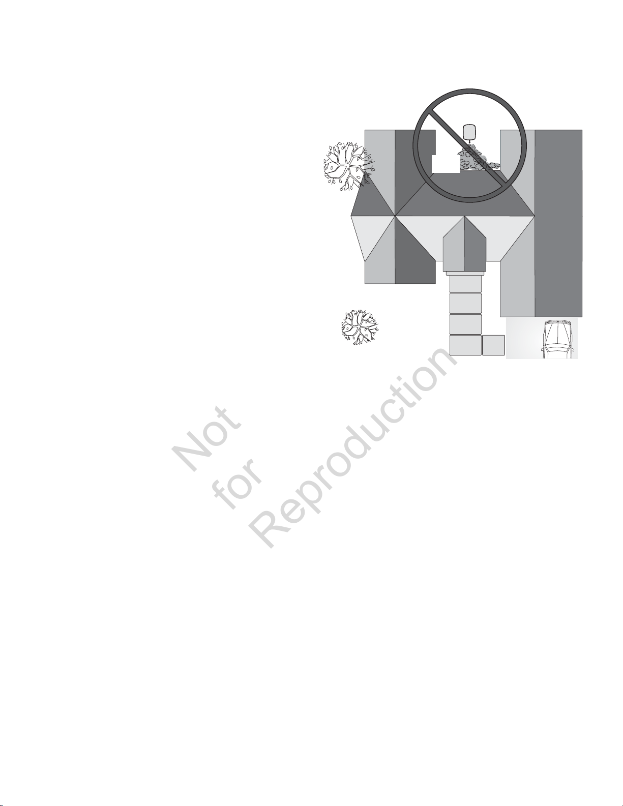
• Dirija el escape el generador lejos de o paralelo
Not
for
Reproduction
al edificio o la estructura. No dirija el escape de
generador hacia una construcción potencialmente
ocupada, la estructura, las ventanas, las puertas,
tomas de ventilación, aberturas de sofito, los
espacios entre plantas, abren puertas de garaje u
otras aperturas donde agotan gas podrían acumular
y podrían entrar dentro o son involucrados en
una construcción o la estructura potencialmente
ocupadas.
• NO coloque el generador de reserva en ninguna
área en donde normalmente se acumulen hojas o
residuos. Coloque el generador de reserva en un lugar
en el que los vientos arrastren el gas de escape fuera
de cualquier edificio o estructura que pueda estar
habitado.
Standby
Generator
Exhaust
Gas
48
Page 49

Colocación de un generador de reserva para reducir el riesgo de incendio
Not
for
Reproduction
La norma NFPA 37 de National Fire Protection Association
(Asociación Nacional de Protección Contra Incendios, NFPA)
establece criterios para reducir al mínimo el riesgo de
incendios durante la instalación y operación de motores
de combustión estacionarios. La norma NFPA 37 limita la
separación entre un generador encerrado y aberturas en
paredes, estructuras y materiales combustibles fuera de la caja.
Los requisitos de colocación proporcionados se basan en
el cumplimiento de la norma NFPA 37 2010, sección 4.1.4 y
en una prueba de demostración de incendio a gran escala.
Los detalles de las pruebas de cumplimiento se pueden
encontrar en la sección correspondiente a requisitos y
pruebas de la norma NFPA 37 de National Fire Protection
Association (NFPA).
ADVERTENCIA Los gases/calor del escape podría encender
combustibles o estructuras y provocar daños materiales,
lesiones graves y/o la muerte.
• NO coloque el lado opuesto del escape de la caja a prueba
de intemperie a menos de 45,7 cm (18 pulgadas) de cualquier
estructura.
• En el lado de salida del escape de la caja a prueba de intemperie
debe haber lo menos 1,5 m (5 pies) libres de cualquier estructura,
arbusto, árbol o cualquier tipo de vegetación.
• La caja a prueba de intemperie del generador de reserva debe
estar por lo menos a 1,5 m (5 pies) de las ventanas, puertas, de
cualquier abertura en la pared, arbusto o vegetación que tenga
más de 30,5 cm (12 pulgadas) de alto.
• La caja a prueba de intemperie del generador de reserva debe
tener un espacio libre mínimo de 1,2 m (4 pies) por arriba respecto
a cualquier estructura, saliente o árbol.
• NO coloque la caja a prueba de intemperie bajo una plataforma u
otro tipo de estructura que pueda limitar el flujo de aire.
• UTILICE SOLAMENTE el tubo de combustible flexible de acero que
se le proporcionó. Conecte al generador el tubo de combustible
que se le proporcionó; NO utilice otro tubo de combustible flexible
ni lo sustituya.
• Los detectores del monóxido de carbono deben ser instalados
y deben ser mantenidos dentro según las instrucciones del
fabricante recomendaciones. Los detectores de humo no pueden
discernir gas de monóxido de carbono.
• NO coloque la caja a prueba de intemperie en ninguna otra
posición que no sea la que se indica.
Ejemplos de ubicaciones del generador de reserva para
reducir el riesgo de incendio:
Espacio Libre Respecto a Estructuras/Vegetación
La caja a prueba de intemperie de reserva debe
A
estar por lo menos a 1,5 m (5 pies) de las ventanas,
puertas, de cualquier abertura en la pared, arbusto o
vegetación que tenga más de 30,5 cm (12 pulgadas)
de alto.
En el lado de salida del escape de la caja a prueba de
B
intemperie debe haber lo menos 1,5 m (5 pies) libres
de cualquier estructura, arbusto, árbol o cualquier
tipo de vegetación.
La caja a prueba de intemperie de reserva debe tener
C
un espacio libre mínimo de 1,2 m (4 pies) por arriba
respecto a cualquier estructura, saliente o árbol.
AVISO NO coloque la caja a prueba de intemperie bajo una
plataforma u otro tipo de estructura que pueda limitar el
flujo de aire.
Espacio libre vertical
B
1,5 m (5 pies)
Agote
Dirección
El centro de Panel de Escape
Estructura
C
1,2 m (4 pies)
Generador
Stand-by
49
Page 50
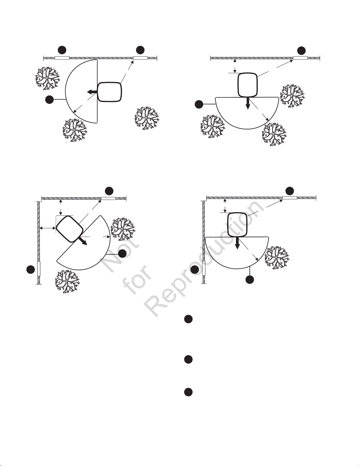
Instalaciones De Una Sola Estructura
Not
for
Reproduction
A A
B
Instalaciones de Dos Estructuras
45,7
cm (18 pulgadas)
Generador
Stand-by
Estructura
Agote
Dirección
1,5 m (5 pies)
Estructura
1,5 m (5 pies)
1,5 m
(5 pies)
Agote
Dirección
Generador
Stand-by
A
1,5 m (5 pies)
B
Arbustos, árboles
o vegitation
45,7
B
45,7
cm (18 pulgadas)
Generador
Stand-by
Agote
Dirección
Estructura
cm (18 pulgadas)
Generador
Stand-by
Agote
Dirección
1,5 m (5 pies)
Estructura
min
1,5 m (5 pies)
1,5 m (5 pies)
1,5 m (5 pies)
A
A
A
A
B
Espacio Libre Respecto a Estructuras/Vegetación
La caja a prueba de intemperie de reserva debe
A
estar por lo menos a 1,5 m (5 pies) de las ventanas,
puertas, de cualquier abertura en la pared, arbusto o
vegetación que tenga más de 30,5 cm (12 pulgadas)
de alto.
En el lado de salida del escape de la caja a prueba de
B
intemperie debe haber lo menos 1,5 m (5 pies) libres
de cualquier estructura, arbusto, árbol o cualquier
tipo de vegetación.
La caja a prueba de intemperie de reserva debe tener
C
un espacio libre mínimo de 1,2 m (4 pies) por arriba
respecto a cualquier estructura, saliente o árbol.
AVISO NO coloque la caja a prueba de intemperie bajo una
plataforma u otro tipo de estructura que pueda limitar el
flujo de aire.
50
Page 51

OTRAS directrices generales de ubicación
Not
for
Reproduction
• Instale el generador de reserva en donde no afecte
• Coloque el generador de reserva en una ubicación
acondicionada que sea plana y cuente con drenaje
de agua.
• Instale el generador de reserva en un lugar en el que
el agua procedente de bombas, canalizaciones de
desagüe, canalones de tejado, sistemas de irrigación
o aspersores no pueda inundarlo, mojar la caja ni
penetrar por las aberturas de entrada o salida de aire.
u obstruya ningún servicio (incluidos los servicios
cubiertos, ocultos y subterráneos), como teléfono,
electricidad, combustible (gas natural/vapor de gas
LP), sistemas de irrigación, aire acondicionado, cable,
fosa séptica, drenaje, pozos, etc.
• Instale el generador de reserva de forma que las
aberturas de entrada y salida de aire no queden
obstruidas por hojas, césped, nieve, etc. Si los vientos
predominantes pueden arrastrar estos materiales,
es posible deberá construir un cortavientos para
proteger la unidad.
Requisitos y pruebas de la norma NFPA 37 de National Fire Protection Association
(NFPA)
Requisitos:
NFPA 37 2010, sección 4.1.4, Motores ubicados a la
intemperie. Los motores y sus compartimientos a prueba
de intemperie, si se proporcionan, que sean instalados a
la intemperie, deben estar a una distancia mínima de 1,5
m (5 pies) de aberturas en paredes y de estructuras que
tienen paredes combustibles. NO se requiere una separación
mínima cuando se presenta alguna de las siguientes condiciones:
1. La pared adyacente de la estructura tiene una
capacidad de resistencia contra incendios de por lo
menos 1 hora.
2. La caja a prueba de intemperie está fabricada de
materiales no combustibles y se ha demostrado
que un incendio dentro de ésta no incendiará los
materiales combustibles que se encuentran fuera de ella.*
* Anexo A Material explicativo
A.4.1.4 (2) Los medios para demostrar el cumplimiento
son pruebas contra incendios realizadas a gran escala o
procedimientos de cálculo, como los que se indican en la
norma NFPA 555, Guide on Methods for Evaluating Potential
for Room Flashover (Guía de métodos para evaluar la
posibilidad de que se produzca una descarga en la habitación).
Para cumplir con la condición 2 anterior, la caja a prueba de
intemperie fue fabricada completamente con materiales no
combustibles y se realizaron pruebas de incendios a gran
escala para demostrar que un incendio dentro de la caja no
incendiará los materiales combustibles que se encuentran
fuera de ella.
Un laboratorio de pruebas reconocido a nivel nacional (NRTL,
por su sigla en inglés) del Departamento de Administración
de Seguridad y Salud Ocupacional (Occupational Safety
& Health Administration, OSHA) de EE. UU. realizó pruebas
de demostración de incendios a gran escala. Este NRTL
externo independiente evaluó muchos de los peores casos
de incendios. Los resultados de las pruebas de demostración
concluyeron que un incendio dentro de la caja no incendiará
los materiales combustibles que se encuentran fuera de ésta.
51
Page 52
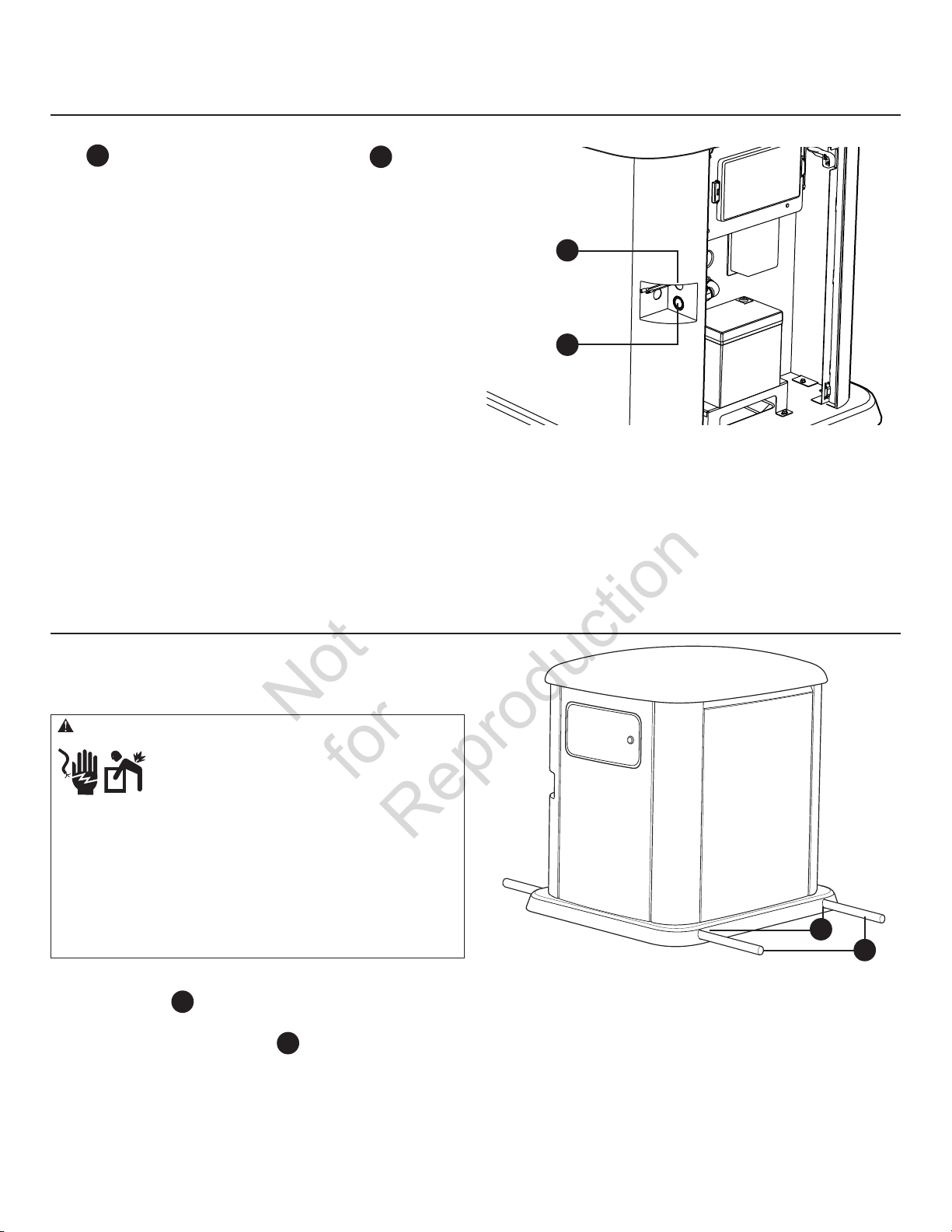
Ubicación de las entradas eléctricas y de combustible
Not
for
Reproduction
El conectador de la admisión de combustible de 3/4 pulgada
N.P.T.
se demuestra:
El sistema de generador de doméstico se envía y
su placa de montaje. A menos que los códigos locales así lo
soliciten, no es necesario construir una losa de concreto.
y la localización eléctrica de la entrada
A
B
a unido a
B
A
Elevación del generador
El generador pesa más de 240 kg (530 libras). Todas las fases
de manipulación y traslado del generador requieren el uso
de herramientas, equipos y profesionales cualificados.
ADVERTENCIA Tensión peligrosa - El contacto con los
cables eléctricos puede provocar electrocución
y quemaduras.
Peligro al elevar el equipo/objeto pesado - Puede
provocar daños en los músculos y en la espalda.
• Si utiliza equipos de elevación o izado, EVITE el contacto con los
cables eléctricos.
• NO eleve ni mueva el generador sin ayuda.
• Utilice tubos de elevación conforme a la sección Elevación
del generador. La unidad se puede mover sobre los tubos de
elevación y provocar lesiones.
• NO levante la unidad por la parte superior; podría provocar daños
en el generador.
Se requieren dos segmentos de 1,22 m (48 pulg.) de tubo
de 2,5 cm (1 pulg.)
antar manualmente el generador. Inserte los tubos a
lev
través de los orificios de elevación
base de la unidad.
ambién puede elevar la unidad con el método de “gancho e
T
izado” colocado en los tubos de elevación, siempre y cuando
utilice una barra separadora para asegurarse de que las
cadenas o cables NO toquen el techo del generador.
C
, suministrados por el instalador, para
ubicados cerca de la
D
D
C
Después de que la unidad esté en su lugar, cubra los orificios
de elevación con los tapones para orificios de elevación
suministrados.
Retoque los desconchones con la pintura que se suministra
a tal efecto.
52
Page 53

Puertas de acceso
Not
for
Reproduction
Cada generador doméstico se suministra con un juego de
llaves idénticas que accionan la cerradura que asegura la
puerta de acceso al panel de control.
Para abrir la puerta de acceso:
1. Inserte la llave en la cerradura de la puerta de acceso
y gire un cuarto de vuelta hacia la izquierda.
2. Retire la llave.
Para cerrar la puerta de acceso:
1. Cierre la puerta del panel de control, inserte la llave
en la cerradura y gire un cuarto de vuelta hacia la
derecha.
2. Retire la llave.
El generador doméstico está equipado con un techo y
paneles laterales desmontables, lo que permite dar un
mantenimiento de manera sencilla.
Para desmontar el techo y el separador:
1. Abra la puerta de acceso al panel de control.
2. Ponga el disyuntor del generador en la posición OFF.
3. Ponga el interruptor del sistema del panel de control
en OFF.
4. Quite el fusible de 15 A del panel de control.
5. Mueva el pestillo del techo hacia la izquierda hasta
que el techo abra ligeramente.
7. Gire los 4 pomos un cuarto de vuelta y levante el
separador.
8. Vuelva a colocar el separador y el techo en orden
inverso.
Para desmontar los paneles laterales:
1. Abra la puerta de acceso al panel de control.
2. Ponga el disyuntor del generador en la posición OFF.
3. Ponga el interruptor del sistema del panel de control
en OFF.
4. Quite el fusible de 15 A del panel de control.
5. Desmonte el techo y el separador.
6. Levante los pestillos
para soltarlos.
en ambos lados del panel
A
6. Levante el techo del generador.
A
7. Tire del panel hacia arriba y hacia afuera de las
ranuras.
53
Page 54

Para desmontar el panel de escape:
Not
for
Reproduction
1. Desmonte el techo y el separador.
2. Desmonte los paneles laterales.
ADVERTENCIA El contacto con la zona del silenciador puede
producir quemaduras graves.
• NO toque las superficies calientes y evite los gases del escape a
alta temperatura.
• Permita que el equipo se enfríe antes de tocarlo.
4. Tire del panel de escape hacia arriba y hacia afuera
de la base.
3. Quite los 6 tornillos
B
B
B
B
del panel de escape.
B
5. Quite los dos tornillos C y saque la cubierta
del silenciador.
C
B
B
6. Vuelva a colocar la cubierta del silenciador y el panel
de escape en orden inverso.
Para instalar los paneles laterales:
1. Coloque el panel en las ranuras y deslícelo hacia
abajo a su lugar.
2. Empuje los pestillos hacia abajo en ambos lados del
panel para trabarlos en su lugar.
3. Vuelva a colocar el separador y el techo.
B
C
54
Page 55
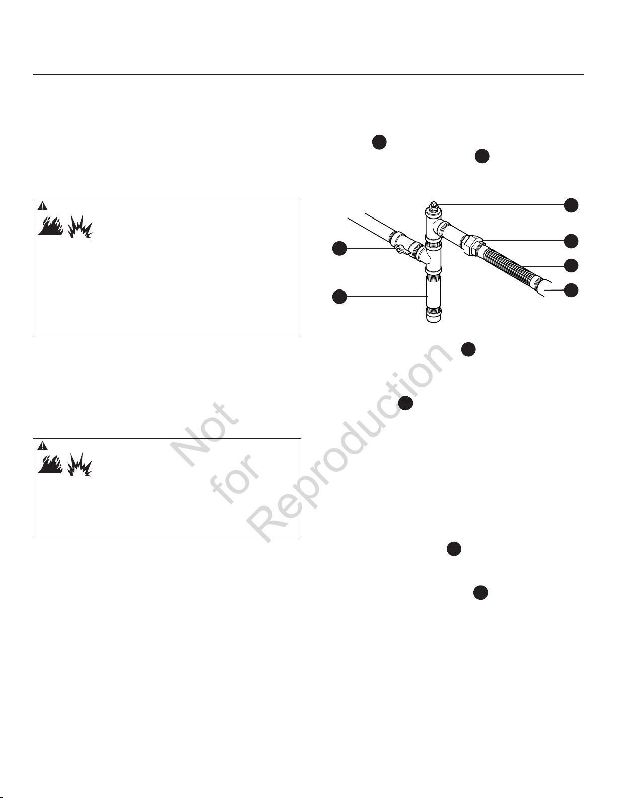
Sistema de combustible gaseoso
Not
for
Reproduction
La siguiente información se proporciona para ayudar
a los técnicos de los sistemas de combustible gaseoso
a planear las instalaciones. En ninguna circunstancia
esta información debe interpretarse en forma contraria
a los códigos aplicables a temas de gas combustible.
Consulte al proveedor de combustible local o al supervisor
del departamento de bomberos si surgen problemas
o preguntas.
ADVERTENCIA El Gas Natural y el Propano son
extremadamente inflamables y explosivos.
El fuego o una explosión pueden causar
quemaduras severas e inclusive la muerte.
• El gas LP es más pesado que el aire y se puede concentrar en
áreas bajas.
• El gas natural es más liviano que el aire y se puede concentrar en
áreas elevadas.
• Hasta la menor chispa puede hacer que estos combustibles se
enciendan y causen una explosión.
• NO encienda un cigarrillo o fume.
AL INSTALADOR: Antes de aplicar estas pautas generales,
consulte al propietario del sistema de generador y
comuníquele cualquier factor técnico a tener en cuenta que
pudiera influir en sus planes de instalación.
Las siguientes son reglas generales que se aplican a las
cañerías utilizadas en los sistemas de combustible gaseoso:
ADVERTENCIA El Gas Natural y el Propano son
extremadamente inflamables y explosivos.
El fuego o una explosión pueden causar
quemaduras severas e inclusive la muerte.
• Antes de poner en servicio el sistema de generador de doméstico,
se deben purgar las líneas del sistema de combustible y se debe
probar si presentan pérdidas.
• No se debe permitir que se produzca ninguna pérdida.
AVISO
La línea flexible suministrada del combustible del
acero es de no ser instalada bajo tierra ni en el contacto con
el suelo.
• Todo el tubo de combustible flexible de acero debe
estar visible para realizarle una inspección periódica
y no debe quedar oculto tras ninguna pared, piso
o mampara, tampoco debe entrar en contacto con
estos elementos ni instalarse de tal manera que los
atraviese.
• Los tubos deben ser de un material que cumpla
con los reglamentos nacionales y locales y deben
montarse rígidamente y protegerse contra
las vibraciones.
• Los tubos deben estar protegidos contra daños físicos
cuando pasen por arriates de flores y arbustos y por
otras zonas cultivadas.
• Instale la línea flexible de combustible de
acero
de combustible del generador A y los tubos rígidos
para evitar que la expansión o contracción térmica
ovoque tensión excesiva en el material de los tubos.
pr
E
F
• Se debe instalar una unión o conexión con brida
en sentido descendente para facilitar el desmontaje
de los mandos.
• Se debe proporcionar un puerto para el
manómetro D. Puede adquirir un manómetro
digital (Ref. 19495) en el centro de servicio de Briggs
& Stratton. Al completar las pruebas iniciales, el
manómetro se quita y el puerto se conecta. El puerto
para manómetro permite instalar de forma temporal
un manómetro para garantizar que el motor reciba la
presión correcta de combustible y opere eficazmente
durante todo el margen de funcionamiento.
• En caso de peligro de formación de hidratos o hielo,
los tubos se deberán proteger contra la congelación.
Los extremos de los tubos duros deben incluir un
colector de sedimentos
no sea susceptible a congelarse.
• Se debe instalar como mínimo una válvula de paso
manual aprobada y accesible
suministr
del generador doméstico.
• Un mínimo de 3 m (10 pies) de tubería para gas entre
el regulador de combustible principal y la conexión de
la entrada de combustible del generador (actúa como
acumulador para cargas del bloque superior).
• Una válvula de paso manual de combustible ubicada
en el interior del edificio.
• En caso de peligro de terremoto, tornado,
inestabilidad del terreno o inundación, se recomienda
(suministrada) entre el puerto de entrada
B
C
F
donde la condensación
E
en el conducto de
o de combustible a menos de 1,8 m (6 pies)
D
C
B
A
55
Page 56

adoptar medidas especiales para mejorar la
Not
for
Reproduction
resistencia y flexibilidad de los soportes y las
conexiones de los tubos.
• La dimensión de los tubos debe ser la adecuada
para mantener la presión y el caudal suficientes en
distintas condiciones de carga del generador, con
todos los equipos de gas conectados al sistema de
combustible y en funcionamiento.
• Use un sellador de tubos o compuesto para uniones
aprobado para uso con NG/LPG en todos los
acoplamientos con rosca para reducir la posibilidad
de fugas.
• Los tubos instalados se deben purgar
adecuadamente y se debe comprobar que no tengan
fugas, de acuerdo con los códigos y estándares
correspondientes.
Presión del combustible
La presión de suministro de combustible de vapor de PL
y gas natural en el puerto de entrada de combustible del
generador debe estar entre los siguientes niveles en carga
completa, con todos los aparatos de gas encendidos y en
funcionamiento.
• GN es de 5 a 7 pulg. de W.C.
• PL es de 11 a 14 pulg. de W.C.
La presión máxima con el motor APAGADO sin carga es de
13,85 psi.
Pérdida de potencia
La densidad del aire es menor en altitudes elevadas,
lo que origina menor potencia disponible del motor.
Específicamente, la potencia del motor se reducirá un 3,5%
por cada 300 metros (1.000 pies) de altitud sobre el nivel
del mar y un 1% por cada 5,6 °C (10 °F) por encima de 25
°C (77 °F). Los generadores ubicados en estas condiciones
deben programarse adecuadamente para dicha disminución
de potencia.
Dimensiones de la cañería de combustible
Existen numerosas referencias en línea o publicadas en
otros medios para conocer el tamaño de la tubería de
combustible. Por ejemplo, el Código Nacional de Gas
Combustible 2006 de NFPA 54 (Artículo N.° 320-6031-06) es
un recurso común.
El instalador debe considerar la densidad específica del gas
y compensar la cantidad normal de restricciones debidas
a curvas, accesorios, etc. En caso de que se use un número
poco frecuente de accesorios, curvas u otras restricciones,
consulte los códigos federales y locales como guía.
56
Page 57

Conversión de combustible
Not
for
Reproduction
El motor del sistema del generador doméstico ha sido
configurado de fábrica para funcionar con gas natural (GN).
También funciona con vapor de petróleo licuado (PL). Se
requiere un juego de conversión a PL (suministrado) para
convertir la unidad a fin de que funcione con combustible
de vapor de PL. La presión de entrada de combustible de PL
debe ser 11 a 14 pulgadas de columna de agua en carga
completa, con todos los aparatos de gas encendidos y
en funcionamiento.
Consumo de combustible
Para configurar el sistema de combustible para usar PL:
1. Coloque el interruptor del sistema del generador en
OFF.
2. Quite el fusible de 15 A del panel de control.
3. Desmonte el techo, el separador, los paneles laterales,
el panel de escape y la cubierta del silenciador.
4. Cambie el propulsor principal del mezclador de
combustible conforme a las indicaciones incluidas en
el juego de conversión a PL.
5. Vuelva a colocar la cubierta del silenciador, el panel
de escape, los paneles laterales, el separador y el
techo.
6. Vuelva a instalar el fusible de 15 A en el panel de
control.
7. Coloque el interruptor del sistema del generador en
AUTO.
El sistema ya está listo para funcionar automáticamente con
combustible de vapor de PL.
A continuación, se muestran los requisitos estimados de
suministro de combustible a plena y media carga de gas
natural y vapor de LP.
11K
Gas natural Vapor de PL
1/2 Carga Carga completa 1/2 Carga Carga completa
82 C 143 C 44 C 73 C
82,000 B 143,000 B 108,350 B 181,200 B
C = en pies cúbicos por hora
B = BTU por hora
13K
Gas natural Vapor de PL
1/2 Carga Carga completa 1/2 Carga Carga completa
93 C 164.4 C 48.64 C 83.08 C
93,000 B 164,400 B 121,600.71 B 207,699.11 B
C = en pies cúbicos por hora
B = BTU por hora
Propiedades
físicas
Estado normal a presión
atmosférica
Punto de ebullición (en °F):
Inicia
Fina
Poder calorífico:
BTU por galón (LHV Neto*)
BTU por galón (bruto**)
Pies cúbicos (gas)
Densidad*** 36.39 57.75
Peso† 4.24 2.65
Número de octanos:
De investigación
Motor
* LHV (poder calorífico inferior) es el valor nominal más realista.
** El poder calorífico bruto no considera la pérdida de calor en forma de agua
durante la combustión.
*** La densidad se expresa en “Pies Cúbicos de Gas por Galón de Líquido”.
† El peso se indica en “Libras por Galón de Líquido”.
Vapor de
PL
Gas Gas
-44
-44
83,340
91,547
2,500
110+
97
-259
-259
63,310
1,000
110+
Gas
natural
57
Page 58

Conexiones de sistema
Not
for
Reproduction
Las conexiones de baja tensión (LV) a los contactos de fallo de señal, comunicación del conectador, LED remoto y alimentación
auxiliar de 12 V CC se realiza con un conector extraíble de diez polos. Compare la ilustración con su generador para
familiarizarse con la conozca la ubicación de estas conexiones. Cuente hasta llegar a la posición de pasador correcta en el
conector de la tarjeta de control debido a que la alineación visual con la calcomanía puede ser confusa.
A
A
- Contactos de fallo - Utilice NO
una sirena, un indicador luminoso, un dispositivo
opcional, etc. como aviso para los casos de fallo. Los
contactos cambian de estado cuando se presenta una
condición de fallo.
- Comunicación con el conectador - Conecte al
B
o de control del conectador para la interfaz de
tabler
comunicación utilizando un cable de cobra de par
torcido 18 AWG.
, COM y NC para activar
B
C
D
E
- LED - No utilizado.
C
- Salida de +12 V CC y 0,5 A - Fuente de alimentación
D
interna auxiliar
E
– 240 V de servicio - Para conectar los cables de ser
de 240 V del conectador al generador.
F
- Cableado para toma de diez alfileres
- Cableado para toma de dos alfileres
G
F
G
.
vicio
• Para la conexión de salida de alimentación, utilice un cable de 300 voltios como mínimo de 90 °C de cobre 6 AWG,
(referencia. Cuadro 310.16, 100 pies del NEC. Utilice el código eléctrico nacional para los factores de corrección y ate con
alambre los cálculos del tamaño.)
• Para la conexión de la red pública, utilice un cable de cobre 14 AWG de 300 voltios como mínimo de 90 °C.
• Para la comunicación del conectador, utilice conductores de par torcido 18 AWG, con una longitud máxima de 61 m, con
cable de cobre de 300 voltios de 90 °C.
• F ije solamente un cable a cada tornillo del conector.
• Apriete los tornillos del conector a 7 pulgadas-libras (7,9 Newton-metro).
58
Page 59

Sistema de conexión de c.a. del generador
Not
for
Reproduction
En el sistema de generador de doméstico se utiliza un
sistema de conexión monofásico de CA de tres hilos. El
conjunto del estator consta de un par de devanados
estacionarios con dos terminales que salen de cada
devanado. La unión de los conductores 22 y 33 forma el
neutro, como se muestra en el diagrama siguiente. El manual
ilustrado de componentes incluye un esquema completo y
un diagrama de conexiones.
AVISO El neutro no está conectado a tierra en el generador.
El conducto
panel de contr
debe sustituirse por un conducto similar.
A
entre la entrada eléctrica de la esquina y el
A
ol es un requisito exigido por UL. Si se quita,
33
22
Devanado eléctrico
11
44
Neutro
120V
120V
Disyuntor
240V
1122 33 440
Conexión a tierra del generador
Conecte a tierra el sistema de generador de doméstico con
arreglo a los códigos y normas vigentes. El terminal GND
(tierra) del generador está situado en el interior de la puerta
del panel de control, bajo la tapa del interruptor.
Tierra
Neutro
Disyuntor
Línea 1Línea 2
Hacia el conectador
59
Page 60

Interconexiones del circuito de control
Not
for
Reproduction
Los cables “240V Utility” (servicio de 240 V) se deben pasar
a través del conducto. “240V Utility” suministra potencia a
la tarjeta de circuito impreso del generador, el calentador
opcional de la batería y de aceite y el cargador de la
batería. El generador arrancará cuando se interrumpa la
alimentación de servicio.
Conecte cada terminal del circuito de control del generador
al conectador automático. Para ello, utilice el conector
bipolar incluido y cable de cobre 14 AWG de 300 V, como
mínimo, suministrado por el instalador.
Comunicación del conectador
(Unidades con un ACCM II o tablero de control
posterior solamente).
Utilizando conductores de par torcido 18 AWG, con
una longitud máxima de 61 m (200 pies), conecte los
terminales Tx Rx y Tx Rx GND desde el panel de control del
generador
ol del conectador B por medio del orificio de acceso
contr
de tensión baja
a los terminales T/R y GND en la tarjeta de
A
.
C
Cuando realice las conexiones, considere el tipo de cable y
las especificaciones de torsión impresas en el disyuntor y
conector neutro/de conexión a tierra.
A
C
B
60
Page 61

Sistema de detección de fallas
Not
for
Reproduction
Tal vez sea necesario que el generador se ponga en
funcionamiento por períodos largos sin que un operario
esté presente. Por esta razón, el sistema está equipado con
detectores que apagan automáticamente el generador en
condiciones de riesgo potencial para el equipo, como baja
presión de aceite, alta temperatura, exceso de velocidad, y
otras condiciones. Para obtener información más detallada,
consulte Sistema de detección de fallos en el manual del
operario.
Panel de control del sistema
A continuación se muestra el panel de control del generador,
situado en el interior del cuerpo del generador.
A continuación se muestra el panel de control del generador,
situado en el interior del cuerpo del generador.
Breve descripción de los mandos utilizados durante
la instalación:
CAD
B
- Set Exercise (Establecer ejercicio) - Permite preparar el
A
ciclo de prueba.
– Disyuntor - Debe estar en ON (Encendido) para
B
suministrar alimentación al conectador
FE
.
C
- Fusible de 15 A - Pr
CC del generador doméstico. Si el fusible se ‘fundió’
(se quemó y abrió) o fue retirado, el motor no puede
arrancar. Cambie el fusible por otro idéntico: ATO de 15
A. La unidad se suministra con un fusible de repuesto.
Si el fusible se fundió o fue retirado, necesitará
reinicializar el temporizador de prueba (consulte la
sección Configuración del temporizador de práctica).
- Conmutador del sistema - Este dispositivo de dos
D
posiciones es el control más importante en el sistema.
Se utiliza de la siguiente manera:
• La posición “AUTO” es la posición normal
funcionamiento. Si se detecta una interrupción de
la alimentación eléctrica de la red, el sistema hace
que arranque el generador. Cuando se restablece la
alimentación eléctrica de la red, el sistema espera
a que se estabilicen las temperaturas internas del
motor, para el generador y se pone en estado de
espera para la próxima vez que se interrumpa la
alimentación eléctrica.
• La posición “OFF” hace que se pare el generador,
impide el arranque de la unidad y reinicializa
cualquier fallo detectado.
E
– MANUAL OVER-RIDE (Cancelación manual) - Activa y
desactiva el generador.
F
- Pantalla digital - Muestra la hora de funcionamiento
en horas o los códigos de falla.
Para obtener más información, consulte la sección Controles
del manual del operario.
otege los circuitos de control de
61
Page 62

Solera de concreto (opcional)
Not
for
Reproduction
Si los códigos locales exigen ese requisito, construya una
losa de concreto que tenga por lo menos 3 pulgadas (76 mm)
de espesor y que sea 6 pulgadas (152 mm) más larga y más
ancha que la unidad (34.6 in (880 mm) x 39.4 in (1000 mm)).
Coloque la unidad sobre la losa utilizando pernos de anclaje
para albañilería de 1/4” (6mm) de diámetro (como mínimo),
que sean lo suficientemente largos para soportar la unidad.
Taladre orificios para pernos de anclaje en la base de la
unidad en las cuatro ubicaciones recomendadas
Mediciones de ubicación para taladrar orifi cios para per-
nos de anclaje
A
B
C
D
5.51 in (140 mm)
23.62 in (600 mm)
16.78 in (426.4 mm)
2.55 in (65 mm)
.
F
B
23.62 in
(600mm)
5.51 in
140
(140mm)
A
F
1/4 in
F F
(6mm)
5.51 in
(140mm)
1.57 in
40
(40mm)
E
16.78 in
426.4
(426.4mm)
C
F
140
A
2.55 in
(65mm)
D
E
F
1.57 in (40 mm)
1/4 in (6 mm) holes
Cubra con grava Base (opcional)
Si puesto bajo el mandato por código local, vacía
un área aproximadamente cinco pulgadas profundas y aproximadamente seis pulgadas más
anchas que la impresión de pie del generador
stand-by. Forre el área con película de poliuretano
y llene de grava de guisante o piedra aplastada.
Comprima y nivele la piedra. Si trozo concreto es
requerido, vea sección Concreta de Trozo en este
manual.
62
Page 63

Consideraciones finales para la instalación
Not
for
Reproduction
Aceite de motor
AVISO Si intenta arrancar el motor antes de llenarlo con el aceite
recomendados, provocará un fallo del equipo.
• Consulte la información de llenado de aceite y combustible en la
sección Mantenimiento y en el manual del operario.
• El daño a la generador, resultado de la desatención a esta
precaución, no será cubierto por la garantía.
El motor se entrega configurado en fábrica y lleno de
aceite sintético (API SJ/CF 5W-30), lo que permite que el
sistema funcione en la gama más amplia de condiciones
de temperatura y climáticas. Antes de arrancar el motor,
compruebe el nivel de aceite como se describe en la sección
Mantenimiento del manual del operario. Antes de ponerlo en
marcha, compruebe el nivel de aceite y asegúrese de que se
sigan los procedimientos de mantenimiento descritos en el
manual del operario.
El hecho de utilizar aceite sintético NO modifica los intervalos
de cambio de aceite necesarios descritos más adelante en la
sección dedicada a mantenimiento en la manual del motor.
Batería
El instalador debe suministrar e instalar una batería
de arranque con válvula de regulación y recargable
12 voltios. La batería de arranque DEBE cumplir con las
especificaciones que se indican en este cuadro.
Especificaciones de la batería
Voltios 12 V CC
A (MÍN) 600 CCA (amperios de arranque en frío)
Tipo AGM
Hardware Terminal M6
Dimensiones (MÁX):
Ancho 5.5 pulgadas (140 mm)
Longitud 9.0 pulgadas (230 mm)
Altura 8.25 pulgadas (210 mm)
Instale la batería como se explica en el apartado Servicio la
Batería de la sección Mantenimiento del manual del operario.
Asegúrese siempre de conectar el cable NEGATIVO en
último lugar y que el aislante del terminal POSITIVO rojo esté
bien colocado.
ADVERTENCIA
El fluido de electrolito de la batería contiene ácido y es
extremadamente cáustico.
El contacto con el fluido de la batería puede causar quemaduras
químicas severas.
Las baterías presentan un riesgo de descarga eléctrica y de
elevada corriente de cortocircuito.
• NO deseche la batería tirándola al fuego. Recicle la batería.
• No permita ninguna llama abierta, chispa, calor, o encienda
un cigarrillo durante y por varios minutos después de haber
recargado la batería.
• NO abra ni manipule la batería.
• Utilice gafas de protección, y delantal, botas y guantes de goma.
• No lleve relojes, anillos ni otros objetos metálicos.
• Utilice herramientas con mangos aislados.
Las baterías almacenadas producen hidrógeno
explosivo mientras estén siendo recargadas.
Una pequeña chispa puede encender el
hidrógeno y causar una explosión.
ADVERTENCIA Las patillas de las baterías, los terminales y los
accesorios relacionados contienen plomo y compuestos de plomo
- sustancias químicas declaradas cancerígenas y causantes de
malformaciones congénitas por el Estado de California. Lávese las
manos después de manipular estos elementos.
63
Page 64
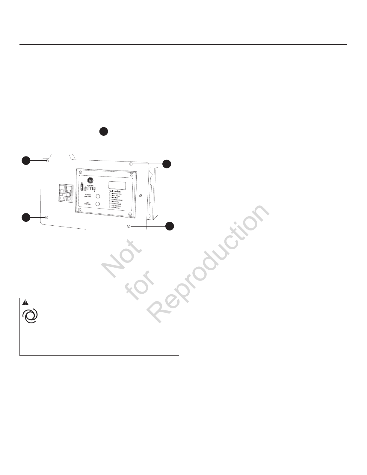
Arranque inicial (sin carga)
Not
for
Reproduction
La unidad se configuró en fábrica para que funcione con
gas natural. La conversión de combustible, si se requiere,
debe completarse antes de realizar estos pasos (consulte
Conversión de combustible).
Antes de poner a funcionar el generador doméstico o
de ponerlo en servicio, inspeccione toda la instalación
cuidadosamente. Posteriormente, comience a probar
el sistema sin conectar cargas eléctricas, de la
siguiente manera.
1. Quite los cuatro tornillos
contr
ol a la caja para dejar al descubierto el disyuntor
de la unidad.
A
A
2. Conecte un medidor de frecuencia de precisión del
lado de carga del interruptor principal del generador.
3. Fije el interruptor de potencia principal del generador
en la posición ON (cerrada).
4. Fije el cconmutador del sistema del generador en la
posición OFF.
ATENCIÓN Instala el fusible se puede producir el arranque
del motor.
• Tenga en cuenta que el fusible de 15 Amperios ha sido retirado
del panel de control para realizar el envío.
• NO instale este fusible hasta que no se hayan completado e
inspeccionado todas las conexiones de cables y tuberías.
que fijan el panel de
A
A
7. Pulse MANUAL OVER RIDE (cancelación manual) en
el panel de control aproximadamente durante seis
segundos. El motor se pondrá en funcionamiento.
Cuando el sistema de generador de doméstico se arranca
por primera vez, es necesario purgar el aire de las líneas de
combustible gaseoso. Esto puede tardar algunos minutos.
8. Escuche si se oyen ruidos anormales o si se observa
vibración u otros indicios de funcionamiento anormal.
Compruebe si se produce alguna fuga de aceite
durante el funcionamiento del generador.
9. Deje que el motor se caliente durante
aproximadamente cinco minutos para permitir que
las temperaturas internas se estabilicen.
10. Verifique la tensión debe estar entre
239 y 262 Voltios y la frecuencia entre 62.0 y 62.5 Hz.
Si alguno de los parámetros está fuera de estos rangos, lleve
a cabo los ajustes del motor que se describen en la sección
Ajuste del motor.
11. Verifique la salida del generador entre una de
las orejetas terminales de conexión al generador
A
NO siga avanzando hasta que no esté seguro de que la
tensión de c.a. del generador y la frecuencia sean las
correctas y se encuentren dentro de los límites establecidos.
Para obtener la frecuencia apropiada del generador,
consulte la sección Ajuste del motor.
12. Pulse y tiene el conmutador MANUAL OVER-RIDE
13. Vuelva a instalar el panel de control en la caja.
y la orejeta terminal de conexión al neutro, luego
entre la otra orejeta de conexión al generador y la
orejeta terminal de conexión al neutro. En ambos
casos, las lecturas de tensión deben estar entre
119 y 131 Voltios.
(cancelación manual) del panel de control hasta
paradas de motor.
5. Instale el fusible de 15 Amperios en el panel
de control.
6. Fije el cconmutador del sistema del generador en la
posición AUTO.
64
Page 65

Ajuste del motor
Not
for
Reproduction
Hay variaciones regionales en la composición del gas
natural. Cada unidad HGS se ajusta en fábrica para
funcionamiento con gas natural. Si la tensión de salida
del generador o la frecuencia medidas durante el
Arranque inicial están fuera de los intervalos admisibles,
la combustibilidad del gas suministrado en el lugar de
instalación puede ser sustancialmente distinta.
Para ajustar el motor para este combustible diferente, haga
lo siguiente.
1. Quite los cuatro tornillos que fijan el panel de control
a la caja para dejar al descubierto el disyuntor
de la unidad.
2. Conecte un medidor de frecuencia de precisión del
lado de carga del interruptor principal del generador.
3. Asegúrese de que el fusible de 15 Amperios se
encuentre instalado.
4. Fije el interruptor de potencia principal del generador
en ON.
5. Sitúe el conmutador del sistema del generador en la
posición AUTO.
6. Pulse el conmutador MANUAL OVER-RIDE
(cancelación manual) del panel de control. Cuando
el motor arranque, déjelo calentar durante
cinco minutos.
7. La frecuencia normal sin carga es de 62,0 a 62,5 Hz.
Si se requiere hacer un ajuste sin carga, desmonte los
paneles laterales de la unidad. Con unos alicates de
punta fina, doble la espiga de anclaje de resorte
lentamente hacia arriba o hacia abajo hasta que la
ecuencia sea de 62,0 a 62,5 Hz
fr
A
8. Sitúe el seccionador de servicio del conectador en la
posición “OFF” (abierto). El conectador se conectará al
generador después de un breve período de tiempo.
9. Cargue el generador a plena carga.
10. La frecuencia debe ser superior a 57,0 Hz.
11. Si la frecuencia es inferior a 57,0 Hz, gire lentamente
el elemento de ajuste del regulador hasta que la
frecuencia sea superior a 57,0 Hz.
12. Sitúe el seccionador de servicio del conectador en la
posición “On” (cerrado). El conectador se conectará a
la red pública después de un breve período de tiempo.
13. Pulse y tiene el conmutador MANUAL OVER-RIDE
(cancelación manual) del panel de control hasta
paradas de motor.
14. Una vez que se pare el motor:
• Si se realizó un ajuste en el paso 11, repita los pasos
del 2 al 7.
• Si no se realizó un ajuste en el paso 11, siga en el
paso 15.
Si la frecuencia sin carga es inferior al parámetro sin carga
después de realizar el ajuste a plena carga, póngase en
contacto con un centro de servicio autorizado.
15. Vuelva a instalar el panel de control en la caja.
A
65
Page 66

Utilización
Not
for
Reproduction
Secuencia de operación automática
El panel de control del generador aloja una plaqueta
de control lógico. Esta plaqueta de control supervisa
constantemente la tensión de origen de energía de la
compañía proveedora de electricidad. Si esa tensión cae por
debajo de un nivel preestablecido, la acción de la plaqueta
de control indica al motor que arranque.
Cuando se restablece la tensión de origen de la compañía
proveedora de electricidad por encima de un nivel de tensión
preestablecida, se indica al motor que se apague.
La operación real del sistema no se puede ajustar y se divide
en secuencias mediante sensores y temporizadores en la
plaqueta de control, de la siguiente manera:
Sensor de caída de tensión de la compañía proveedora
de electricidad
• Este sensor supervisa la tensión de origen de la
compañía proveedora de electricidad.
• Si la tensión de origen de la compañía proveedora
de electricidad cae por debajo de aproximadamente
el 70 por ciento de la tensión de suministro nominal,
el sensor energiza un temporizador de 10 segundos.
El temporizador se utiliza para detectar caídas
de tensión.
• Una vez transcurrido el tiempo del temporizador, el
motor arranca en forma manual.
Sensor de excitación de tensión de la compañía
proveedora de electricidad
Este sensor vigila la tensión de alimentación de la red.
Cuando se restablece la tensión alcanzando un valor
superior al 80% de la tensión nominal, se pone en marcha
un temporizador y el motor sigue funcionando durante un
tiempo para enfriarse.
Temporizador de enfriamiento del motor
• Cuando la carga se transfiere nuevamente a la
fuente de energía de la compañía proveedora de
electricidad, comienza el conteo de tiempo del
temporizador de enfriamiento del motor.
• El temporizador funciona durante aproximadamente
un minuto, luego el generador se apaga.
• El tiempo mínimo de funcionamiento del motor es
de 5 minutos.
66
Page 67

Configuración del temporizador de práctica
Not
for
Reproduction
El generador doméstico está euipado con un temporizador
de práctica ue arranca el sistema y lo prueba una vez cada
siete días. Durante este período de práctica, la unidad
trabaja durante aproximadamente 20 minutos y luego
se apaga. Durante el ciclo de práctica NO se produce la
transferencia de cargas eléctricas (a menos ue se produzca
un corte en el suministro de la compañía proveedora
de electricidad).
El panel de control incluye un botón “Set Exercise” (Preparar
prueba) (consulte Panel de control del sistema). La fecha
y la hora concretas en las ue se pulsa dicho botón están
programadas en la memoria de la tarjeta de control. Esta
información se utiliza para iniciar automáticamente el ciclo
de prueba del sistema. La leyenda “SET EXERCISE” del panel
de control parpadeará hasta ue se active el ciclo de prueba.
Para llevar a cabo el procedimiento para configurar la
práctica (Set Exercise):
1. Elija el día y la hora en que desea que se realice la
práctica del generador doméstico.
2. Ese día y a esa hora, pulse y mantenga pulsado el
conmutador “Set Exercise” (Preparar prueba) durante
tres segundos.
La presentación de “Ejercicio de Conjunto” iluminará
entonces apaga para confirmar que el reloj de
ejercicio ha sido puesto. Entonces suelte el botón Fijo
de Ejercicio.
La unidad acodar y correrá el ciclo de ejercicio.
Durante el ciclo, Ejercicio de Conjunto iluminará.
Una vez el ciclo de ejercicio es completo, la unidad
apagará y “Ejercicio de Conjunto” ya no será
demostrado.
El ciclo de Ejercicio puede ser discontinuado en
girando en cualquier momento el Interruptor de
Sistema a LEJOS.
3. Posteriormente, la unidad arrancará y realizará su
ciclo de prueba de 20 minutos.
Por ejemplo, si pulsa el botón “Set Exercise” el domingo en
la mañana a las 10:00 a.m., la unidad realizará un ciclo de
prueba inmediato y un ciclo de prueba cada domingo a las
10:00 a.m. (+/- 1/2 hora).
La función de configuración de práctica (“Set Exercise”) sólo
funciona si la unidad se encuentra en el modo AUTO y si se
cumple este procedimiento en forma estricta. El dispositivo
de prueba deberá rearmarse si el fusible de 15 A se cambia o
retira o si la batería de arranque se desconecta.
Si desea cambiar el día y la hora en que se realiza la práctica
de la unidad, simplemente realice el procedimiento de
configuración de práctica (“Set Exercise”) exactamente el día
de la semana y a la hora en que desea que se lleve a cabo.
El generador no se probará si el temporizador no se ha
programado.
67
Page 68

Inspección posterior a la instalación
Not
for
Reproduction
Antes de poner el sistema generador en servicio, inspeccione
toda la instalación cuidadosamente.
Ha terminado de realizar las instrucciones de instalación
y de arranque. El manual del operario incluye detalles
completos sobre la operación, el mantenimiento y la
resolución de problemas de este sistema generador.
es una marca registrada de General Electric
Company y se utiliza con licencia por
Briggs & Stratton Power Products Group, LLC.
68
Copyright © 2011. Reservados todos los derechos. Queda prohibida la
reproducción o transmisión total o parcial de este material, sin el permiso
previo y por escrito de Briggs & Stratton Power Products Group, LLC.
Page 69
GE Home Generator Systems
Not
for
Reproduction
Groupe électrogène
Manuel d’installation
et démarrage
Page 70

Nous vous remercions d’avoir acheté cette génératrice résidentielle de ualité GE. Nous sommes heureux ue vous
Not
for
Reproduction
fassiez confiance à la marue GE. Lorsue utilisée et entretenue selon les instructions de ce manuel, votre génératrice
GE vous offrira de nombreuses années de service fiable.
Ce manuel contient des renseignements sur la sécurité pour vous informer des dangers et des risques associés aux
groupes électrogènes ainsi que de la façon de les éviter. Le groupe électrogène est conçu pour être utilisé comme
génératrice résidentielle auxiliaire fournissant une source d’électricité alternative et pour desservir des charges
comme le chauffage, les systèmes de réfrigération et les systèmes de communication qui, lorsqu’ils sont arrêtés
durant une panne d’électricité, peuvent causer de l’inconfort ou des inconvénients. Conservez ces instructions
d’origine pour référence future.
Cette génératrice résidentielle auxiliaire exige une installation par un professionnel avant d’être utilisée. Votre
installateur doit suivre ces directives à la lettre.
Où nous trouver
Vous n’aurez jamais à chercher bien loin pour trouver un centre de soutien et service pour votre génératrice.
Consultez les Pages Jaunes. De nombreux distributeurs de service après-vente agréés GE offrent un service
de qualité. Vous pouvez également communiquer avec le service à la clientèle en téléphonant sans frais au
888 575 8226 de 8 h à 17 h HNC, ou cliquez sur SERVICE & SUPPORT à www.homestandbygeneratorsystems.com,
qui procure une liste des détaillants autorisés.
Pour la future référence
Veuillez fournir les renseignements suivants et les conserver avec votre reçu pour vous aider dans l’identification de
l’appareil lors de vos prochains achats d’équipement.
Date d’achat
Génératrice
Numéro de modèle
Révision
Numéro de série
Moteur
Numéro de modèle
70
Page 71

Table des matiêres
Not
for
Reproduction
Directives importantes. . . . . . . . . . . . . . . . . . . . . . . . . . . . . . . . . . . . . . . . . 72
Veuillez conserver ces instructions . . . . . . . . . . . . . . . . . . . . . . . . . . . . . . . . . . . . . . . . . 72
Installation . . . . . . . . . . . . . . . . . . . . . . . . . . . . . . . . . . . . . . . . . . . . . . . . . . . 76
Responsabilités du propriétaire . . . . . . . . . . . . . . . . . . . . . . . . . . . . . . . . . . . . . . 76
Responsabilités du détaillant/de l’entrepreneur chargé de l’installation. . . . . . . . 76
Trousse pour les temps froids . . . . . . . . . . . . . . . . . . . . . . . . . . . . . . . . . . . . . . . . . . . . . 76
Précautions lors du déballage. . . . . . . . . . . . . . . . . . . . . . . . . . . . . . . . . . . . . . . . . . . . . . 77
Vérification de la livraison . . . . . . . . . . . . . . . . . . . . . . . . . . . . . . . . . . . . . . . . . . . . . . . . . 77
Contenu de la boîte . . . . . . . . . . . . . . . . . . . . . . . . . . . . . . . . . . . . . . . . . . . . . . . . . . . . . . . 77
Liste de vérification d’installation . . . . . . . . . . . . . . . . . . . . . . . . . . . . . . . . . . . . . . . . . . 78
Mise en place de la génératrice . . . . . . . . . . . . . . . . . . . . . . . . . . . . . . . . . . . . . . . . . . . . 78
Mise en place de la génératrice de secours pour
réduire le risque d’empoisonnement au monoxyde de carbone . . . . . . . . . . . . . . . 79
Mise en place de la génératrice de secours pour réduire le risque d’incendie . . . 81
AUTRES directives générales concernant l’emplacement . . . . . . . . . . . . . . . . . . . . . 83
Exigences et tests de la norme NFP37 de la National Fire Protection Association 83
Emplacements de l’admission du combustible et de l’entrée électrique. . . . . . . . . 84
Soulèvement de la génératrice. . . . . . . . . . . . . . . . . . . . . . . . . . . . . . . . . . . . . . . . . . . . . 84
Portes d’accès. . . . . . . . . . . . . . . . . . . . . . . . . . . . . . . . . . . . . . . . . . . . . . . . . . . . . . . . . . . . 85
Le système de combustible gazeux . . . . . . . . . . . . . . . . . . . . . . . . . . . . . . . . . . . . . . . . . 87
Conversion du combustible . . . . . . . . . . . . . . . . . . . . . . . . . . . . . . . . . . . . . . . . . . . . . . . . 89
Consommation de combustible . . . . . . . . . . . . . . . . . . . . . . . . . . . . . . . . . . . . . . . . . . . . 89
Connexions de système . . . . . . . . . . . . . . . . . . . . . . . . . . . . . . . . . . . . . . . . . . . . . . . . . . . 90
Système de branchement C.A. de la génératrice . . . . . . . . . . . . . . . . . . . . . . . . . . . . . 91
Mise à la masse de la génératrice . . . . . . . . . . . . . . . . . . . . . . . . . . . . . . . . . . . . . . . . . . 91
Interconnexions du circuit de commande . . . . . . . . . . . . . . . . . . . . . . . . . . . . . . . . . . . 92
Communication du commutateur de transfert. . . . . . . . . . . . . . . . . . . . . . . . . . . . . . . 92
Système de détection des pannes . . . . . . . . . . . . . . . . . . . . . . . . . . . . . . . . . . . . . . . . . . 92
Système de détection des pannes . . . . . . . . . . . . . . . . . . . . . . . . . . . . . . . . . . . . . . . . . . 93
Tableau de commande du système . . . . . . . . . . . . . . . . . . . . . . . . . . . . . . . . . . . . . . . . . 93
Dalle en béton (en option) . . . . . . . . . . . . . . . . . . . . . . . . . . . . . . . . . . . . . . . . . . . . . . . . . 94
Considérations pour l’installation finale. . . . . . . . . . . . . . . . . . . . . . . . . . . . . . . . . . . . . 95
Démarrage initial (sans charge) . . . . . . . . . . . . . . . . . . . . . . . . . . . . . . . . . . . . . . . . . . . . 96
Réglage du moteur . . . . . . . . . . . . . . . . . . . . . . . . . . . . . . . . . . . . . . . . . . . . . . . . . . . . . . . 97
Fonctionnement. . . . . . . . . . . . . . . . . . . . . . . . . . . . . . . . . . . . . . . . . . . . . . . 98
Séquence de fonctionnement automatique. . . . . . . . . . . . . . . . . . . . . . . . . . . . . . . . . . 98
Réglage de la minuterie de cycle d’exercice . . . . . . . . . . . . . . . . . . . . . . . . . . . . . . . . . 99
Vérification installation . . . . . . . . . . . . . . . . . . . . . . . . . . . . . . . . . . . . . . . . . . . . . . . . . . . 99
71
Page 72
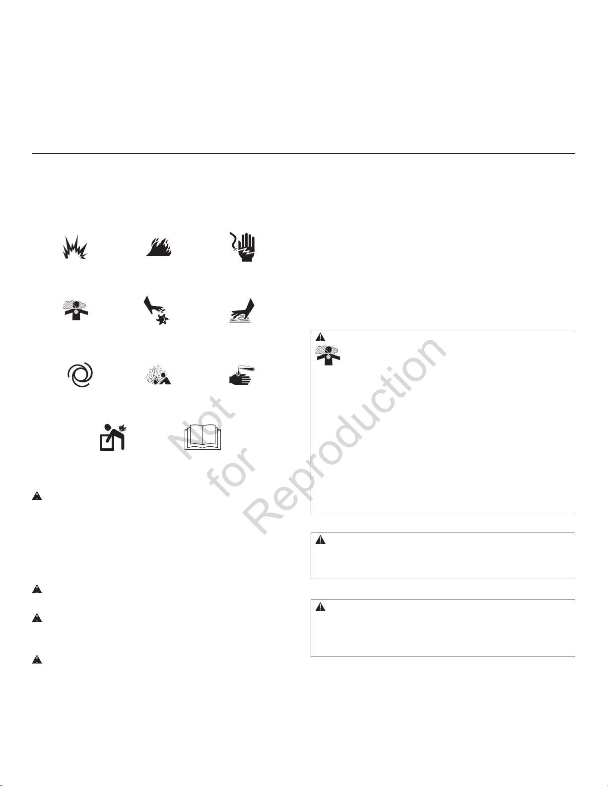
Directives importantes
Not
for
Reproduction
Veuillez conserver ces instructions
CONSERVEZ CES DIRECTIVES – Ce manuel renferme
d’importantes directives qu’il faut suivre durant l’installation
et l’entretien de la génératrice et des batteries.
Symboles de sécurité et leur signification
Explosion
Emanations Toxiques
Risque de Levage Lire le Manuel
Le symbole d’alerte de sécurité indique un risque potentiel
de blessure personnelle. Un mot signal (DANGER, ATTENTION
ou AVERTISSEMENT) est utilisé avec un symbole d’alerte pour
vous indiquer le degré ou le niveau du risque. Un symbole de
sécurité peut être utilisé pour représenter le type de risque.
Le mot signal AVIS est utilisé pour traiter les pratiques qui ne
sont pas reliées aux blessures personnelles.
Le mot signal DANGER indique un danger qui, s’il n’est
pas évité, causera la mort ou des blessures graves.
Le mot signal AVERTISSEMENT indique un risque
qui, s’il n’est pas évité, pourrait causer la mort ou des
blessures graves.
Le mot signal ATTENTION indique un risque qui, s’il
n’est pas évité, pourrait causer des blessures mineures
ou modérées.
Le mot AVIS est utilisé pour les pratiques qui ne sont pas
reliées aux blessures personnelles.
Feu
Parties en Mouvement Surface Chaude
Pression ExplosiveAuto Démarrage
Choc Électrique
Brûlures Chimiques
Le fabriquant ne peut anticiper toutes les circonstances
potentielles pouvant comporter un danger. Par conséquent,
les avertissements contenus dans le présent manuel,
ainsi que les plaques et les décalques apposés sur l’unité
n’englobent pas toutes les possibilités. Si vous utilisez
une procédure, une méthode de travail ou une technique
d’opération non spécifiquement recommandée par le
fabricant, vous devez vous assurer qu’elle ne compromet
pas votre sécurité ni celle des autres. Vous devez également
vous assurer que la procédure, la méthode de travail ou la
technique d’opération que vous choisissez ne rende pas la
génératrice dangereuse.
AVERTISSEMENT Un moteur en marche dégage du monoxyde de
carbone, un gaz inodore, incolore et toxique. L’inhalation du
monoxyde de carbone peut entraîner la mort, des blessures
graves, des maux de tête, de la fatigue, des étourdissements,
des vomissements, de la confusion, des crises épileptiques, des
nausées et l’évanouissement.
• Faites fonctionner la génératrice UNIQUEMENT à l’extérieur, dans un
endroit où les gaz d’échappement mortels ne s’accumuleront pas.
• Assurez-vous que les gaz d’échappement sont éloignés des fenêtres,
des portes, des prises d’aération, des orifices de ventilation dans
l’avant-toit, des vides sanitaires, des portes de garage ouvertes
ou de toute autre ouverture par lesquelles les gaz d’échappement
pourraient pénétrer à l’intérieur ou être aspirés dans les espaces d’un
édifice qui pourraient être occupés.
• Les détecteurs monoxyde de carbone doivent être installés et doivent
être maintenus à la maison selon les recommandations des instructions
du fabricant. Les détecteurs de fumée ne peuvent pas détecter du gaz
monoxyde de carbone.
AVERTISSEMENT L’échappement du moteur de ce produit
contient des produits chimiques que l’État de Californie considère
comme causant le cancer, des déformations à la naissance ou
d’autres dangers concernant la reproduction.
AVERTISSEMENT Certains composants de ce produit ainsi
que les accessoires reliés contiennent des produits chimiques
reconnus par l’État de la Californie comme causant des cancers,
des malformations congénitales, ou d’autres problèmes de
reproduction. Nettoyez-vous les mains après la manipulation.
72
Page 73

AVERTISSEMENT Les batteries d’accumulateur produisent
Not
for
Reproduction
du gaz hydrogène explosif lorsqu’elles
se rechargent.
La plus petite étincelle enflammera
l’hydrogène et provoquera une explosion.
Le liquide d’électrolyte de l’accumulateur contient de l’acide et est
extrêmement caustique.
Le contact avec le liquide de l’accumulateur provoquera de graves
brûlures chimiques.
Toute batterie présente un risque de choc électrique et de courant
de court-circuit élevé.
• NE jetez PAS la batterie dans un feu. Recyclez la batterie.
• Ne laissez aucune flamme, étincelle, source de chaleur ou
cigarette allumée pendant ou plusieurs minutes suivant la charge
de l’accumulateur.
• N’ouvrez PAS ni N’endommagez la batterie.
• Portez des lunettes de sécurité ainsi qu’un tablier, des bottes et
des gants en caoutchouc.
• Enlevez votre montre, vos bagues et tout autre objet de métal.
• Utilisez des outils avec des poignées isolées.
AVERTISSEMENT Le gaz propane et le gaz naturel sont
extrêmement inflammables et explosifs.
Le feu ou l’explosion risque de provoquer des
blessures graves, pouvant être fatales.
• Installez le système d’alimentation de combustible conformément
aux codes applicables aux combustibles et aux gaz.
• Avant de mettre en service le génératrice d’état d’attente, il faut
purger adéquatement les lignes d’alimentation de combustible et
les tester pour les fuites.
• Une fois le système installé, vous devez vérifier le système de
combustible sur une base régulière.
• Aucune fuite ne peut être tolérée.
• NE faites PAS fonctionner le moteur si vous sentez une odeur de
combustible ou si d’autres conditions d’explosion sont présentes.
• Abstenez-vous de fumer près de la génératrice. Essuyez
immédiatement tout déversement d’huile. Assurez-vous de ne
laisser aucun matériau combustible dans le compartiment de
la génératrice. Gardez la zone autour de la génératrice propre
et sans débris.
AVERTISSEMENT Le générateur produit une tension élevée.
Ne pas relier le générateur à la terre risque de provoquer
des électrocutions.
NE PAS isoler le générateur de l’installation électrique
risque de provoquer des blessures ou même d’être fatal
pour les ouvriers électriciens et de causer des dommages au
générateur dus à un “backfeed” d’énergie électrique
• Lorsque vous utilisez le générateur comme source d’énergie de
secours, il est nécessaire d’aviser les services publics d’électricité.
• NE touchez PAS aux fils ou aux prises dénudés.
• N’utilisez PAS le générateur avec des cordons électriques usés,
effilochés ou dénudés, ou abîmés de quelque sorte que ce soit.
• NE manipulez PAS le générateur ou les cordons d’alimentation
lorsque vous êtes debout dans l’eau, pieds nus ou avec les mains
ou les pieds humides.
• Si vous devez travailler aux environs d’une unité alors qu’elle
est en marche, placez-vous sur une surface sèche isolée afin de
réduire les risques de choc électrique.
• NE laissez PAS des personnes non qualifiées ou des enfants se
servir ou réparer le générateur.
• En cas d’accident causé par un choc électrique, procédez
immédiatement à la mise hors tension de l’alimentation électrique
et contacter des autorités locales. Évitez tout contact direct
avec la victime.
• En dépit de la conception sécuritaire du groupe électrogène, le fait
d’opérer l’équipement de façon imprudente, de ne pas l’entretenir
ou d’être négligent peut causer des blessures et la mort.
• Demeurez alerte en tout temps lorsque vous travaillez sur cet
équipement. NE travaillez JAMAIS sur l’équipement si vous êtes
fatigué physiquement ou mentalement.
• Avant de procéder à tout entretien sur la génératrice, débranchez
tout d’abord le câble de batterie identifié par NEGATIVE, NEG ou
(-). Rebranchez le câble après avoir terminé.
• Une fois votre groupe électrogène installé, la génératrice peut
se lancer et démarrer sans avertissement lorsque survient une
panne électrique. Pour prévenir des blessures potentielles, AVANT
de travailler sur l’équipement, réglez toujours l’interrupteur de
système sur OFF, ET enlevez le fusible de 15 Ampères.
73
Page 74

AVERTISSEMENT Tension dangereuse - Tout contact avec les
Not
for
Reproduction
lignes d’électricité peut causer un choc électrique
ou des brûlures.
Risque de levage/Objet lourd - Peut entraîner un
claquage musculaire ou des blessures au dos.
• Si vous utilisez un appareil de levage, prenez garde de NE PAS
toucher aux lignes d’électricité.
• NE soulevez ni ne déplacez PAS la génératrice sans aide.
• Utilisez les tuyaux de levage tel que décrit dans la section Levage
de la génératrice. L’unité peut glisser sur les tuyaux de levage lors
du déplacement et ainsi causer des blessures.
• NE soulevez PAS l’unité par sa partie supérieure car cela
endommagera la génératrice.
AVERTISSEMENT Démarreur et autre tourneres peut empêtrer
mains, cheveux, vêtement, ou accessoires.
• N’utilisez JAMAIS la génératrice sans bâtis, couvercles ou gardes
de protection installés.
• NE portez PAS de vêtements lâches, de bijoux ou tout ce
qui risquerait d’être pris dans le démarreur ou toute autre
pièce rotative.
• Embouteiller des cheveux longs et enlève la bijouterie.
• Avant l’entretien, ôtez le fusible de 15 ampères du tableau de
commande et débranchez le câble de batterie Négatif (NEG ou -).
AVERTISSEMENT Tout contact avec la zone du silencieux peut
causer des brûlures graves.
La chaleur et les gaz d’échappement peuvent
enflammer des matériaux combustibles et les
structures ainsi que causer un incendie.
• NE touchez PAS aux pièces chaudes et évitez le contact avec les
gaz d’échappement.
• Laissez l’équipement refroidir avant de le toucher.
• NE placez PAS le côté opposé à l’échappement du boîtier étanche
à moins de 45,7 cm (18 po) de toute structure.
• Le dégagement entre le côté avec sortie d’air du boitier et toute
structure, tout arbre ou arbuste ou toute végétation doit être d’au
moins 1,5 m (5 pi).
• Le boîtier étanche de la génératrice de secours doit être situé à
au moins 1,5 m (5 pi) des fenêtres, des portes, des ouvertures,
des arbustes ou de la végétation ayant plus de 30 cm (12 po) de
hauteur.
• Le dégagement entre le dessus du boîtier étanche de la
génératrice de secours et toute structure, tout porte-à-faux ou
tout arbre doit être d’au moins 1,2 m (4 pi).
• NE placez PAS le boîtier étanche sous une terrasse ou n’importe
quelle autre structure qui pourrait limiter la circulation d’air.
• UTILISEZ SEULEMENT la conduite d’alimentation en carburant
en acier flexible fournie. Raccordez la conduite d’alimentation
en carburant fournie à la génératrice; N’utilisez AUCUNE autre
conduite d’alimentation flexible.
• Installez et entretenez des détecteurs de fumée à l’intérieur
conformément aux instructions et recommandations du
fabricant. Les détecteurs de CO ne peuvent pas détecter la fumée.
• Laissez au moins les distances minimum indiquées dans
les Mise en place de la génératrice afin de vous assurer d’un
refroidissement approprié de la génératrice et des dégagements
requis pour l’entretien.
• L’utilisation ou le fonctionnement d’un moteur sur un terrain
boisé, couvert de broussailles ou gazonné constitue une violation
dans l’État de la Californie, en vertu de la section 4442 du
California Public Resources Code, à moins qu’il ne soit doté d’un
pare-étincelles tel que défini dans la section 4442 et maintenu
en bon état de fonctionnement. Il se peut que d’autres États ou
d’autres compétences fédérales aient des lois semblables.
Communiquez avec le fabricant, le détaillant ou le
concessionnaire original de l’appareil afin d’obtenir un pareétincelles conçu pour le système d’échappement installé
sur ce moteur.
• Les pièces de rechange doivent être identiques aux pièces
d’origine et être installées à la même position.
74
Page 75

ATTENTION L’installation du fusible pourrait causer le
Not
for
Reproduction
démarrage du moteur.
• Prenez note que, avant l’expédition, le fusible de 1 Ampères a été
retiré du panneau électrique.
• N’installez PAS ce fusible avant que toute la plomberie et le
câblage n’aient été complétés et vérifiés.
ATTENTION Les vitesses de fonctionnement excessivement
élevées augmentent les risques de blessure ou risquent
d’endommager le génératrice.
Des vitesses excessivement lentes produisent une charge
importante pour la génératrice.
• NE trafiquez PAS la vitesse régulée. Le génératrice produit une
fréquence nominale et une tension correctes lorsqu’il fonctionne à
une vitesse régulée.
• NE modifiez PAS le génératrice d’aucune façon.
AVIS Un traitement inapproprié du génératrice risque de
l’endommager et de raccourcir sa durée d’utilisation.
• Ne vous servez du générateur que pour les utilisations prévues.
• Si vous avez des questions concernant les utilisations prévues,
demandez à votre distributeur ou revendeur autorisé.
• Ne faites fonctionner le générateur que sur des
surfaces horizontales.
• Des débits d’air de refroidissement et d’aération adéquats sont
nécessaires au bon fonctionnement de la génératrice.
• Lorsque l’unité est en marche, il faut que les portes
soient installées.
• N’exposez pas le générateur à une humidité excessive, à de la
poussière, à de la saleté ou à des vapeurs corrosives.
• Demeurez alerte en tout temps lorsque vous travaillez sur cet
équipement. Ne travaillez jamais sur l’équipement si vous êtes
fatigué physiquement ou mentalement.
• Ne démarrez jamais le moteur sans son filtre à air ou sans le
couvercle du filtre à air.
• N’insérez aucun objet dans les fentes de refroidissement.
• N’utilisez pas la génératrice ni aucune partie de celle-ci comme
palier. Le fait de marcher sur l’unité peut causer des contraintes
et briser des pièces. Cela peut résulter en des conditions de
fonctionnement dangereuses à cause d’une fuite de gaz
d’échappement, de combustible, d’huile, etc.
• Si les appareils branchés sont en surchauffe, éteignez-les et
débranchez-les du générateur.
• Arrêtez le générateur si :
- la puissance électrique est inexistante;
- l’équipement produit des étincelles, de la fumée ou des
flammes;
- l’unité vibre excessivement;
- l’unité fait des bruits curieux.
75
Page 76

Installation
Not
for
Reproduction
Ce produit est conçu pour être utilisé comme groupe
électrogène optionnel fournissant une source d’électricité
alternative et pour desservir des charges comme le
chauffage, les systèmes de réfrigération et les systèmes
de communication qui, lorsqu’ils sont arrêtés durant une
panne d’électricité, peuvent causer des inconforts ou autre.
Ce produit ne se qualifie pas comme groupe électrogène
d’urgence tel que défini par la NFPA 70 (NEC).
Tout a été fait pour s’assurer que les renseignements
contenus dans le présent guide soient exacts et à jour.
Toutefois, le fabriquant se réserve le droit de changer, de
modifier ou encore d’amélorer le système en tout temps et
ce, sans préavis.
Seuls des entrepreneurs en électricité et en plomberie
qualifiés devraient procéder à l’installation des groupes
électrogènes. Toute installation doit être conforme à tous
codes de sécurité applicables, ainsi qu’aux normes et à la
réglementation de l’industrie.
Responsabilités du propriétaire
• Vous devez lire et suivre les instructions indiquées
dans le manuel d’utilisation.
• Établissez un programme d’entretien, de soins et
d’utilisation régulier de votre groupe électrogène, tel
qu’indiqué dans le manuel d’utilisation.
• Les détecteurs monoxyde de carbone doivent être
installés et doivent être maintenus à la maison selon
les recommandations des instructions du fabricant. Les
détecteurs de fumée ne peuvent pas détecter du gaz
monoxyde de carbone.
Responsabilités du détaillant/de l’entrepreneur chargé de l’installation
• Vous devez lire et respecter les règles de sécurité
décrites dans le manuel d’utilisation.
• Installez uniquement un commutateur de transfert
homologué UL qui est compatible avec le
groupe électrogène.
• Vous devez lire et suivre les instructions indiquées
dans le présent guide d’installation.
• Toute installation doit être conforme à tous codes
de sécurité applicables, ainsi qu’aux normes et à la
réglementation de l’industrie.
• Permettre la pièce suffisante de tous côtés du
générateur pour l’entretien et d’entretenir.
Trousse pour les temps froids
Nous RECOMMANDONS FORTEMENT d’installer une trousse
pour les temps froids de modèle 6030 (incluant un chauffebatterie et un réchauffeur d’huile) lorsque la génératrice est
utilisée à des températures inférieures à 5 °C (40 °F). Ces
articles sont disponibles auprès de votre détaillant local.
If you need more information on this matter, please call
(888) 575-8226, between 8:00 AM and 5:00 PM CT.
76
Page 77

Précautions lors du déballage
Not
for
Reproduction
Avant son expédition, l’unité prête à installer a été placée
sur une dalle de béton armé ou une base artificielle. Prenez
soins d’éviter les dommages causés par une chute, un choc,
une collision, etc. Entreposez et déballez la boîte dans le bon
sens, tel qu’indiqué sur le carton d’expédition.
Vérification de la livraison
Après avoir enlevé le carton, examinez avec soin les
éléments de la génératrice pour tout dommage subi durant
l’expédition.
Au moment de la livraison, si vous remarquez des
dommages ou des pièces manquantes, demandez au
livreur de noter tous les dommages sur la facture de fret
Contenu de la boîte
Le groupe électrogène est livré avec les éléments suivants:
• Berceau de montage préfixé
• Système de lubrification viabilisé
• La ligne de carburant en acier flexible
• Guide d’installation et de démarrage
• Manuel d’utilisation
• Clés pour la porte d’accès
• Fusible de rechange de 15 ampères ATO
• Connecteur à deau épingles pour tableau de
commande
• Connecteur à dix épingles pour tableau de commande
• Peinture de retouche
• Bouchons pour les trous de levage (4)
• Trousse de conversion au GPL
et d’apposer sa signature dans l’espace réservé à cette fin.
Après la livraison, si vous remarquez des pièces manquantes
ou des dommages, mettez les pièces endommagées de
côté et communiquez avec le transporteur pour connaître
les procédures de réclamation. Les pièces manquantes ou
endommagées ne sont pas garanties.
Articles non fournis :
• Batterie de demurrage
• Conduit et fil de branchement
• Vannes/tuyauterie d’alimentation en combustible
• Grue, sangles de levage, chaînes ou câbles
• Deux tuyaux de 122 cm (48 po) de long d’un diamètre
de 2,54 cm (1 po) (PAS des conduits électriques)
• Tournevis à couple, plage de 5 à 50 pouces-livres
• Voltmètre/fréquencemètre
77
Page 78

Liste de vérification d’installation
Not
for
Reproduction
Les tâches suivantes doivent être accomplies afin d’installer
correctement la génératrice :
Détecteur de monoxyde de carbone
Détecteur de monoxyde de carbone en bon état de
fonctionnement.
Positionnement
Les permis requis ont été obtenus.
Génératrice placée dans une zone sécuritaire relativement
Génératrice placée dans une zone sécuritaire relativement
Génératrice placée dans une zone sécuritaire relativement
Génératrice placée dans une zone sécuritaire relativement
Génératrice placée dans une zone sécuritaire relativement
Essence
La génératrice est reliée à une source d’essence par un
La pression appropriée de l’essence a été mesurée alors
Le moteur de votre système de génératrice résidentielle
au monoxyde de carbone. Consultez Positionnement de la
génératrice afin de réduire le risque d’empoisonnement
par du monoxyde de carbone.
à l’incendie. Consultez Positionnement de la génératrice
afin de réduire le risque d’incendie.
à l’endommagement par l’eau. Consultez Autres directives
générales concernant l’emplacement.
à l’électricité. Consultez Autres directives générales
concernant l’emplacement.
aux débris. Consultez Autres directives générales
concernant l’emplacement.
conduit d’essence flexible, sans fuite et conforme aux
codes locaux. Consultez Le système de combustible
gazeux.
que tous les appareils à gaz étaient en marche. Consultez
Le système de combustible gazeux.
est configuré c en usine pour utiliser le gaz naturel (GN). Il
peut également fonctionner avec de la vapeur de pétrole
liquéfié (PL). Consultez Conversion du Combustible.
Alimentation électrique
Le neutre de la génératrice est relié au commutateur
La génératrice est mise à la terre. Consultez Mise à la terre
La génératrice est reliée à un commutateur de transfert à
En utilisant deux conducteurs torsadés de calibre 18, pas
Mode d’utilisation
Une batterie de type approprié est installée et
Le niveau d’huile à moteur de la génératrice est à la
L’alimentation de service est coupée pour tester le
de transfert automatique. Consultez Système de
branchement C.A. de la génératrice.
de la génératrice.
l’aide du câblage spécifié. Consultez Connexion du circuit
d’alimentation de service et communication avec le
commutateur de transfert.
plus de 60 m (200 pieds) de long, raccordez Tx Rx et Tx Rx
GND à partir du tableau de commande de la génératrice
aux bornes T/R et GND du module de commande du
commutateur de transfert par l’ouverture d’accès basse
tension .Connexion du circuit d’alimentation de service
et communication avec le commutateur de transfert.
Les interrupteurs à positions multiples dans la plupart
de commutateurs de transfert doivent être réglés pour
correspondre à la puissance en watts du générateur..
Consultez Connexion du circuit d’alimentation de service
et communication avec le commutateur de transfert.
La trousse pour les temps froids est installée, au besoin.
Consultez Trousse pour les temps froids
complètement chargée. Consultez Considérations pour
l’installation finale.
marque maximum (« FULL »). Consultez Considérations
pour l’installation finale.
fonctionnement de la génératrice et du commutateur de
transfert. Vérifiez la présence de codes de défaillance et
apportez les corrections requises.
Mise en place de la génératrice
Avant d’installer la génératrice, consultez le propriétaire
et faites-lui part des exigences suivantes, qui doivent être
satisfaites avant d’effectuer l’installation.
Il ya deux problèmes de sécurité tout aussi important en
ce qui concerne intoxication au monoxyde de carbone
et d’incendie. Il ya également plusieurs lignes directrices
emplacement général qui doivent toutes être remplies avant
que l’installation est considérée comme complète.
AVERTISSEMENT Un moteur en marche dégage du monoxyde de
carbone, un gaz inodore, incolore et toxique. L’inhalation du
monoxyde de carbone peut entraîner la mort, des blessures
graves, des maux de tête, de la fatigue, des étourdissements,
des vomissements, de la confusion, des crises épileptiques, des
nausées et l’évanouissement.
• Faites fonctionner la génératrice UNIQUEMENT à l’extérieur, dans un
endroit où les gaz d’échappement mortels ne s’accumuleront pas.
• Assurez-vous que les gaz d’échappement sont éloignés des fenêtres, des
portes, des prises d’aération, des orifices de ventilation dans l’avant-toit,
des vides sanitaires, des portes de garage ouvertes ou de toute autre
ouverture par lesquelles les gaz d’échappement pourraient pénétrer à
l’intérieur ou être aspirés dans les espaces d’un édifice qui pourraient
être occupés.
• Les détecteurs monoxyde de carbone doivent être installés et doivent
être maintenus à la maison selon les recommandations des instructions
du fabricant. Les détecteurs de fumée ne peuvent pas détecter du gaz
monoxyde de carbone.
Epuiser Côté du Générateur
A
Epuiser côté du générateur.
A
Le côté opposé à l’échappement du boîtier étanche.
B
B
78
Page 79

Mise en place de la génératrice de secours pour
B
D
E
F
G
C
Not
for
Reproduction
réduire le risque d’empoisonnement au monoxyde de carbone
Les fl èches dans le point de la fi gure ci-dessus mentionnée aux points POTENTIELS d'entrée pour l'échappement
monoxyde de carbone.
B
Tous les appareils à combustible fossile, comme les
génératrices de secours, contiennent du monoxyde de
carbone (CO) dans l’échappement du moteur. Le CO et
inodore, incolore et insipide, et il est peu probable qu’on le
remarque jusqu’à ce qu’une personne perde connaissance.
Le CO peut vous tuer, c’est pourquoi il est essentiel que les
mesures suivantes soient comprises dans l’installation :
• IInstallez la génératrice à l’extérieur, dans un endroit
où les gaz d’échappement mortels ne s’accumuleront
pas.
• N’installez PAS la génératrice dans un endroit où
les gaz d’échappement pourraient s’accumuler et
pénétrer ou être aspirés dans les espaces d’un édifice
qui pourraient être occupés.
• Dans plusieurs États, la Loi exige qu’un détecteur
de monoxyde de carbone fonctionnel soit installé
dans votre maison. Installez et entretenez des
détecteurs de monoxyde de carbone à l’intérieur
conformément aux instructions et recommandations
du fabricant
est un dispositif électronique qui détecte les niveaux
dangereux de CO. S’il y a une accumulation de CO, le
moniteur alertera les occupants en faisant clignoter
une lampe témoin et en déclenchant une alarme. Les
détecteurs de fumée ne peuvent pas détecter le CO.
• La maison de votre voisin peut aussi être exposée aux
gaz d’échappement de votre génératrice de secours
et vous devez en tenir compte lorsque vous installez
votre génératrice
. Un moniteur de monoxyde de carbone
• Assurez-vous que les gaz d’échappement sont:
A
éloignés des fenêtres
des portes
A
des orifices de ventilation dans l’avant-toit
A
des vides sanitaires
A
des portes de garage
A
autre ouverture par lesquelles les gaz
A
d’échappement pourraient pénétrer à l’intérieur
ou être aspirés dans les espaces d’un édifice qui
pourraient être occupés
A
A
79
Page 80

• Diriger l’échappement de générateur d’état d’attente
Not
for
Reproduction
loin de ou parallèle au bâtiment ou à la structure.
PAS dirige l’échappement de générateur vers une
construction potentiellement occupée, une structure,
une fenêtres, une portes, une prises de ventilation, les
conduits de soffite, rampent des espaces, ouvrir les
portes de garage ou les autres ouvertures où le gaz
d’échappement pourrait accumuler et pourrait entrer
à l’intérieur ou est dessiné dans une construction ou
une structure potentiellement occupée.
• NE placez PAS la génératrice auxiliaire dans un
endroit où des feuilles ou des débris s’accumulent
habituellement. Installez la génératrice auxiliaire
dans un endroit où les vents transporteront les gaz
d’échappement loin des immeubles ou structures qui
pourraient être occupés.
Standby
Generator
Exhaust
Gas
80
Page 81
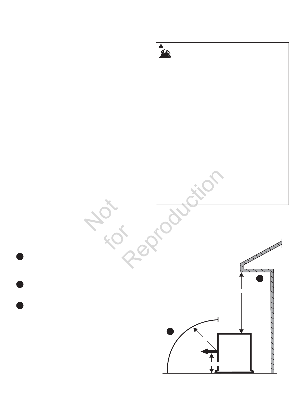
Mise en place de la génératrice de secours pour réduire le risque d’incendie
Not
for
Reproduction
La norme NFPA 37 de la National Fire Protection Association
(NFPA) des États-Unis établit des critères visant à minimiser le
risque d’incendie pendant l’installation et le fonctionnement
de moteurs fixes à combustion. La norme NFPA 37 limite
l’espacement entre une génératrice et les ouvertures dans
les murs, les structures et les matériaux combustibles à
l’extérieur du boîtier.
Les exigences en matière de mise en place qui sont fournies
sont basées sur la conformité avec la norme NFPA 37 2010
section 4.1.4, et sur un essai de démonstration de réaction
au feu pleine échelle. On peut trouver les détails des tests de
conformité dans la section sur les exigences et les tests de
la norme NFP37 de la National Fire Protection Association
(NFPA).
AVERTISSEMENT La chaleur et les gaz d’échappement peuvent
enflammer les matériaux combustibles et les structures et
entraîner la mort, des blessures graves ou des dommages
matériels.
• NE placez PAS le côté opposé à l’échappement du boîtier étanche
à moins de 45,7 cm (18 po) de toute structure.
• Le dégagement entre le côté avec sortie d’air du boitier et toute
structure, tout arbre ou arbuste ou toute végétation doit être d’au
moins 1,5 m (5 pi).
• Le boîtier étanche de la génératrice de secours doit être situé à
au moins 1,5 m (5 pi) des fenêtres, des portes, des ouvertures,
des arbustes ou de la végétation ayant plus de 30 cm (12 po) de
hauteur.
• Le dégagement entre le dessus du boîtier étanche de la
génératrice de secours et toute structure, tout porte-à-faux ou
tout arbre doit être d’au moins 1,2 m (4 pi).
• NE placez PAS le boîtier étanche sous une terrasse ou n’importe
quelle autre structure qui pourrait limiter la circulation d’air.
• UTILISEZ SEULEMENT la conduite d’alimentation en carburant
en acier flexible fournie. Raccordez la conduite d’alimentation
en carburant fournie à la génératrice; N’utilisez AUCUNE autre
conduite d’alimentation flexible.
• Les détecteurs de fumée doivent être installés et doivent
être maintenus à la maison selon les recommandations des
instructions du fabricant. Les alarmes monoxyde de carbone ne
peuvent pas détecter de la fumée.
• NE placez PAS la génératrice d’une autre façon que celle illustrée.
Exemple d’emplacement pour la génératrice de secours
pour réduire le risque d’incendie :
Le boîtier étanche de la génératrice de secours
A
doit être situé à au moins 1,5 m (5 pi) des fenêtres,
des portes, des ouvertures, des arbustes ou de la
végétation ayant plus de 30 cm (12 po) de hauteur.
Le dégagement entre le côté avec sortie d’air du
B
boitier et toute structure, tout arbre ou arbuste ou
toute végétation doit être d’au moins 1,5 m (5 pi).
Le dégagement entre le dessus du boîtier étanche
C
de la génératrice de secours et toute structure, tout
porte-à-faux ou tout arbre doit être d’au moins
1,2 m (4 pi). NE placez PAS le boîtier étanche sous
une terrasse ou n’importe quelle autre structure qui
pourrait limiter la circulation d’air.
Dégagements verticaux
B
1,5 m (5 pi)
Des gaz
d’échappement
Le centre de Panneau d’Echappement
Structure
C
1,2 m (4 pi)
Générateur
stand-by
81
Page 82

Installations à Une Structure
Not
for
Reproduction
B
Installations
45,7
A A
d’échappement
à
Deux Structures
cm (18 po)
Générateur
stand-by
Structure
Des gaz
1,5 m (5 pi)
Structure
1,5 m (5 pi)
1,5 m
(5 pi)
Des gaz
d’échappement
1,5 m (5 pi)
Générateur
stand-by
A
B
Arbustes, arbres
ou végétations
B
d’échappement
45,7
cm (18 po)
Des gaz
d’échappement
45,7
cm (18 po)
Générateur
Des gaz
Générateur
stand-by
1,5 m (5 pi)
min
stand-by
1,5 m (5 pi)
Structure
Structure
1,5 m (5 pi)
1,5 m (5 pi)
A
A
A
A
B
Exemple d’emplacement pour la génératrice de secours
pour réduire le risque d’incendie :
Dégagement Des Structures et de la Végétation
Le boîtier étanche de la génératrice de secours
A
doit être situé à au moins 1,5 m (5 pi) des fenêtres,
des portes, des ouvertures, des arbustes ou de la
végétation ayant plus de 30 cm (12 po) de hauteur.
Le dégagement entre le côté avec sortie d’air du
B
boitier et toute structure, tout arbre ou arbuste ou
toute végétation doit être d’au moins 1,5 m (5 pi).
Le dégagement entre le dessus du boîtier étanche
C
de la génératrice de secours et toute structure, tout
porte-à-faux ou tout arbre doit être d’au moins
1,2 m (4 pi). NE placez PAS le boîtier étanche sous
une terrasse ou n’importe quelle autre structure qui
pourrait limiter la circulation d’air.
82
Page 83

AUTRES directives générales concernant l’emplacement
Not
for
Reproduction
• Placez la génératrice de secours dans un endroit
préparé à cet effet qui soit plat et muni d’un drain
pour l’écoulement des eaux.
• Installez la génératrice de secours dans un endroit où
l’évacuation d’une pompe de puisard, l’écoulement
des gouttières et du toit, l’irrigation d’aménagement
paysagé ou un système de pulvérisation d’eau
n’entraînera pas une inondation de l’appareil,
l’arrosage du boîtier ou l’entrée d’eau par l’admission
d’air ou les ouvertures de sortie.
• Installez la génératrice de secours à un endroit où
les services (incluant les services couverts, enfermés
et souterrains), dont le téléphone, l’électricité,
l’alimentation en combustible (gaz naturel/vapeur de
GPL), l’irrigation, la climatisation, le câble, le réservoir
septique, les égouts, le puits, etc. ne seront pas
touchés ni obstrués.
• Installez la génératrice de secours là où les feuilles, le
gazon, la neige, etc. n’obstrueront pas l’entrée d’air et
les ouvertures de sortie d’air. Si des vents dominants
causent des bourrasques ou des amoncellements, il
faut construire un brise-vent pour protéger l’appareil.
Exigences et tests de la norme NFP37 de la National Fire Protection Association
Exigences :
NFPA 37 2010, section 4.1.4, Engines Located Outdoors
(moteurs installés à l’extérieur). Les moteurs et leur boîtier
étanche, s’il y a lieu, qui sont installés à l’extérieur doivent
être situés à au moins 1,5 m (5 pi) de toute ouverture dans
un mur et à au moins 1,5 m (5 pi) de toute structure ayant
des murs combustibles. La séparation minimale n’est pas
nécessaire si l’une ou l’autre des conditions suivantes est
présente :
1. L’indice de résistance au feu du mur adjacent de la
structure est au moins d’une heure.
2. Le boîtier étanche est fait de matériaux
incombustibles et il a été démontré qu’un incendie à
l’intérieur du boîtier n’enflammera pas les matériaux
combustibles à l’extérieur du boîtier. *
* Annexe A Document explicatif
A.4.1.4 (2) Il est permis de démontrer la conformité au moyen
d’essais de réaction au feu pleine échelle ou par des calculs
tels que ceux indiqués dans la norme NFPA 555, Guide on
Methods for Evaluating Potential for Room Flashover.
Pour se conformer à la condition 2 ci-dessus, le boîtier
étanche a été construit entièrement de matériaux
incombustibles et des essais de réaction au feu pleine
échelle ont été effectués afin de démontrer qu’un incendie
à l’intérieur du boîtier n’enflammera pas les matériaux
combustibles à l’extérieur du boîtier.
Un laboratoire d’essai du U.S. Department of Labor
Occupational Safety & Health Administration (OSHA) reconnu
au niveau national a effectué les essais de démonstration
de réaction au feu pleine échelle. Ce laboratoire d’essais
indépendant reconnu au niveau national a évalué de
nombreux scénarios de pire éventualité. Les résultats des
essais de démonstration permettent de conclure qu’un
incendie à l’intérieur du boîtier n’enflammerait pas des
matériaux combustibles à l’extérieur du boîtier.
83
Page 84

Emplacements de l’admission du combustible et de l’entrée électrique
Not
for
Reproduction
Le connecteur de prise de carburant de 3/4 pouce N.P.T.
et l’endr
Le génératrice d’état d’
montage avant l’expédition. Sauf si stipulé par un code local,
aucune dalle en béton n’est nécessaire.
oit électrique d’admission
attente a été fixé à son berceau de
est montré à la droite.
B
A
Soulèvement de la génératrice
La génératrice pèse plus de 240 kg (530 livres). Il faut utiliser
des outils et de l’équipement appropriés et recourir à un
personnel qualifié pour chacune des phases de manipulation
et de déplacement de l’unité.
AVERTISSEMENT Tension dangereuse - Tout contact avec les
lignes d’électricité peut causer un choc électrique
ou des brûlures.
Risque de levage/Objet lourd - Peut entraîner un
claquage musculaire ou des blessures au dos.
• Si vous utilisez un appareil de levage, prenez garde de NE PAS
toucher aux lignes d’électricité.
• NE soulevez ni ne déplacez PAS la génératrice sans aide.
• NE soulevez PAS l’unité par sa partie supérieure car cela
endommagera la génératrice.
B
A
Deux tuyaux de 122 cm (48 po) de long d’un diamètre de
2,54 cm (1 po)
soulever la génératrice manuellement
à travers les trous de levage
l’unité.
ous pouvez également soulever l’unité à l’aide d’un
V
crochet ou d’un palan fixé aux tuyaux de levage, en autant
qu’une barre d’écartement soit utilisée pour s’assurer
que les chaînes ou les câbles soient dégagés du toit de la
génératrice.
C
fournis par l’installateur sont requis pour
. Insérez les tuyaux
D
situés près de la base de
84
D
C
Lorsque l’unité est en place, bouchez les trous de levage à
l’aide des bouchons pour les trous de levage fournis.
Il y a des pochettes de levage dans chaque coin, entre la
base de la génératrice et son berceau de montage. À l’aide
de la peinture pour retouche fournie, effectuez les retouches
de peinture pour toute surface écaillée.
Page 85

Portes d’accès
Not
for
Reproduction
Un jeu de clés identiques est fourni avec chaque génératrice
résidentielle. Ces clés s’adaptent aux serrures qui verrouillent
les portes d’accès du tableau de commande.
Pour ouvrir une porte d’accès :
1. Insérez une dans la serrure de la porte d’accès
et tournez la clé d’un quart de tour dans le sens
antihoraire.
2. Retirez la clé.
Pour fermer une porte d’accès :
1. Fermez la porte du tableau de commande et insérez
une clé dans la serrure et tournez la clé d’un quart de
tour dans le sens horaire.
2. Retirez la clé.
La génératrice résidentielle est dotée d’un toit et de
panneaux latéraux amovibles pour l’entretien simple.
Pour enlever le toit et le séparateur :
1. Ouvrez la porte d’accès du tableau de commande.
2. Réglez le disjoncteur de la génératrice à la position
OFF.
3. Réglez l’interrupteur du système du tableau de
commande à OFF.
4. Retirez le fusible de 15 A du tableau de commande
5. Déplacez le verrou de toit vers la gauche jusqu’à ce
que le toit se soulève légèrement.
7. Tournez les boutons d’un quart de tour et soulevez le
séparateur.
8. Replacez le séparateur et le toit dans l’ordre inverse.
Pour retirer les panneaux latéraux :
1. Ouvrez la porte d’accès du tableau de commande
2. Réglez le disjoncteur de la génératrice à la position OFF.
3. Réglez l’interrupteur du système du tableau de
commande à OFF.
4. Retirez le fusible de 15 A du tableau de commande.
5. Retirez le toit et le séparateur.
6. Soulevez les verrous A des deux côtés du panneau
pour le libér
7. Tirez le panneau vers le haut et à l’extérieur des
rainures.
er.
6. Soulevez le toit de la génératrice.
A
85
Page 86
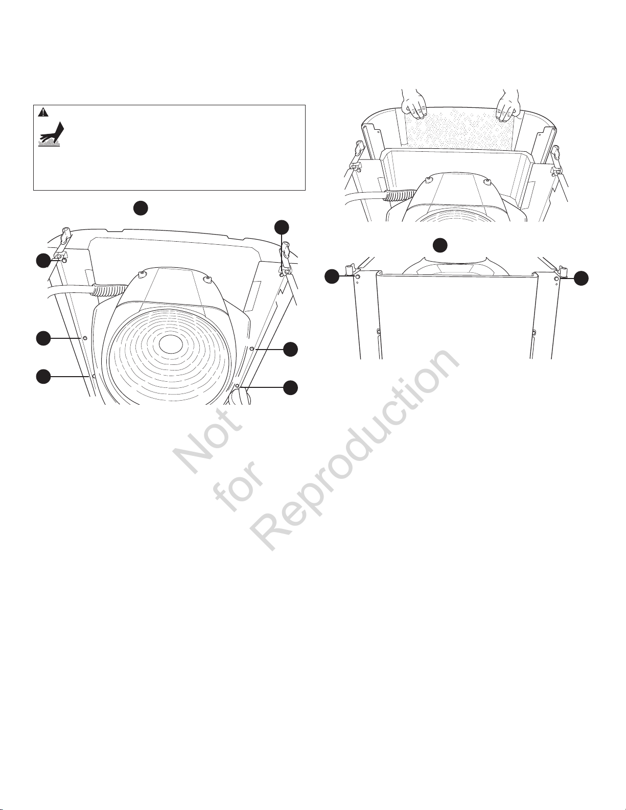
Pour retirer le panneau d’échappement:
Not
for
Reproduction
1. Retirez le toit et le séparateur.
2. Retirez les panneaux latéraux.
AVERTISSEMENT Tout contact avec la zone du silencieux peut
causer des brûlures graves.
• NE touchez PAS aux pièces chaudes et évitez le contact avec les
gaz d’échappement.
• Laissez l’équipement refroidir avant de le toucher.
4. Tirez le panneau d’échappement vers le haut et à
l’extérieur de la base.
3. Enlevez les 6 vis
B
B
B
du panneau d’échappement.
B
B
5. Retirez les deux vis
C
B
6. Replacez le couvercle du silencieux et le panneau
B
d’échappement dans l’ordre inverse.
Pour installer les panneaux latéraux:
1. Placez le panneau dans la rainure et faites-le glisser
en place.
2. Appuyez sur les verrous des deux côtés du panneau
pour les fixer.
3. Replacez le séparateur et le toit.
C
et le couvercle du silencieux.
C
86
Page 87

Le système de combustible gazeux
Not
for
Reproduction
Les renseignements ci-dessous aideront les techniciens
en systèmes de combustible gazeux à concevoir les
installations. Ces renseignements ne doivent en aucun
cas être interprétés de façon à aller à l’encontre des codes
applicables aux combustibles gazeux. Si vous avez des
questions ou des problèmes, consultez votre fournisseur
de combustible local ou votre chef des pompiers.
AVERTISSEMENT Le gaz propane et le gaz naturel sont
extrêmement inflammables et explosifs.
Le feu ou l’explosion risque de provoquer des
blessures graves, pouvant être fatales.
• Le gaz de pétrole liquéfié est plus lourd que l’air et s’accumule
près du sol.
• Le gaz naturel est plus léger que l’air et s’accumule en hauteur.
• Même la plus petite étincelle peut enflammer ces combustibles et
causer une explosion.
• N’allumez PAS de cigarette ou ne fumez pas à proximité
de l’appareil.
À L’INSTALLATEUR: Avant d’appliquer ces consignes
générales, consultez le propriétaire du groupe électrogène et
soulevez toute considération technique qui pourrait influer
sur ses plans d’installation.
Les règles générales suivantes s’appliquent à la tuyauterie
des systèmes de combustible gazeux :
AVERTISSEMENT Le gaz propane et le gaz naturel sont
extrêmement inflammables et explosifs.
Le feu ou l’explosion risque de provoquer des
blessures graves, pouvant être fatales.
• Avant de mettre en service le groupe électrogène, il faut purger
adéquatement les lignes d’alimentation de combustible et les
tester pour les fuites.
• Aucune fuite ne peut être tolérée.
AVIS Le connecteur ne doit pas être installé sous terre ou être en
contact avec la sol.
• Il faut que toute la longueur du conduit d’essence
flexible en acier soit visible pour l’inspection régulière
et il ne doit pas être enfermé ni toucher ou traverser
un mur, un plancher ou une cloison.
• La tuyauterie doit être fabriquée d’un matériau
conforme aux codes de sécurité fédéraux et locaux;
elle doit être fixée solidement et protégée contre les
vibrations.
• La tuyauterie doit être protégée contre les dommages
physiques aux endroits où elle traverse les massifs
de fleurs, les massifs d’arbustes ainsi que les
autres surfaces cultivées susceptibles de subir des
dommages.
• Installer la ligne de carburant en acier flexible
(fournis) entr
de la génératrice
d’empêcher l’expansion thermique ou la contraction
de causer une contrainte excessive aux matériaux de
la tuyauterie.
E
F
• Un raccord union
êtr
e installé en aval de sorte à permettre le retrait
des commandes.
• Il faudrait inclure une sortie pour manomètre
. Un manomètre numérique, no de pièce 19495, est
disponible à votr
Lorsque la série initiale d’essais est complétée, le
manomètre est enlevé et la sortie bouchée. La sortie
pour manomètre permet l’installation temporaire
d’un manomètre, afin de s’assurer que le moteur
reçoit la pression de carburant adéquate pour
fonctionner efficacement dans l’ensemble de sa plage
de fonctionnement.
• La tuyauterie doit être protégée contre le gel dans
les régions propices à la formation d’hydrates ou de
glace. La terminaison de la tuyauterie rigide devrait
inclure une trappe à sédiments
où le condensat ne gèle habituellement pas.
• Au moins un robinet de fermeture manuelle
approuvé
alimentation en combustible à l’intérieur de 180 cm
d’
(6 pi) de la génératrice résidentielle.
• Une section de tuyau de gaz d’un minimum de
3 m (10 pi) doit être installée entre le régulateur
principal de combustible et les connexions de l’orifice
d’admission de combustible (sert d’accumulateur
pour les charges élevés de blocs).
• Un robinet de fermeture manuelle du carburant situé
à l’intérieur de l’édifice.
e l’orifice d’admission de combustible
A
et la tuyauterie rigide afin
C
ou un raccord à brides doit
e centre de service Briggs & Stratton.
dans les régions
F
doit être installé sur la ligne
E
B
D
D
C
B
A
87
Page 88

• Lorsque les conditions locales impliquent des
Not
for
Reproduction
tremblements de terre, des tornades, un sol instable
ou des risques d’inondation, des considérations
spéciales doivent être apportées afin d’augmenter
la force et la flexibilité des supports et des
raccordements de la tuyauterie.
• La tuyauterie doit être de la bonne dimension afin
de maintenir les pressions d’alimentation ainsi
que le débit volumétrique nécessaires sous les
diverses conditions de la génératrice alors que
tous les appareils au gaz sont reliés au système
d’alimentation et en fonctionnement.
• Afin de réduire la possibilité de fuites, utilisez un
scellant ou un composé approuvé pour joints de
tuyauterie de gaz naturel ou de pétrole liquéfié sur
tous les raccords à visser.
• Conformément aux codes et aux normes applicables,
la tuyauterie installée doit être adéquatement purgée
et testée au niveau de son étanchéité.
Pression du combustible
La pression d’alimentation en vapeur de PL et en gaz naturel
à l’orifice d’alimentation de combustible de la génératrice
devrait se situer entre les niveaux suivants, lorsque tous les
appareils au gaz sont sous tension et en fonction.
• GN est 5-7 po CE
• PL est 11-14 po CE
La pression maximale avec le moteur à l’arrêt et sans charge
est de 13,8 lb/po2.
Perte de puissance
La densité de l’air étant moindre en haute altitude, la
puissance du moteur est donc réduite. En fait, la puissance
du moteur sera réduite de 3,5 % pour chaque (300 m (1 000
pieds) au-dessus du niveau de la mer, et de 1 % pour chaque
5,6° C (10° F) au-dessus de 25° C (77° F). Les génératrices
se trouvant dans ces conditions nécessitent que leur
commutateur de transfert soit correctement programmé en
fonction de cette baisse de puissance. .
Grosseur du tuyau de combustible
Il existe de nombreux documents de référence, en ligne
ou non, sur les dimensions des tuyaux de combustible. Par
exemple, NFPA 54 – National Fuel Gas Code, 2006 (Art. No
: 320-6031-06) est une ressource consultée fréquemment.
L’installateur doit tenir compte de la gravité spécifique du
gaz et compenser pour une quantité nominale de restrictions
causées par les lyres de dilatation, les joints, etc. Si la
quantité de raccords, de coudes ou d’autres restrictions est
inhabituelle, consultez les codes fédéraux et locaux.
88
Page 89
Conversion du combustible
Not
for
Reproduction
Le moteur de votre système de génératrice résidentielle
est calibré en usine pour utiliser le gaz naturel (GN). Il
peut également fonctionner avec de la vapeur de pétrole
liquéfié (PL). Une trousse de conversion au pétrole liquéfié
(fournie) est nécessaire pour la conversion de l’unité pour la
vapeur de pétrole liquéfié. Toutefois, la pression d’entrée du
combustible de pétrole liquéfié doit se situer entre 11 et 14
pouces d’eau à pleine capacité, lorsque tous les appareils au
gaz sont sous tension et en fonction.
Pour configurer le système de combustible pour le pétrole
liquéfié:
1. Réglez l’interrupteur de système à OFF.
2. Retirez le fusible de 15 A du tableau de commande.
3. Retirez le toit, le séparateur, les panneaux latéraux,
le panneau d’échappement et le couvercle
du silencieux.
4. Changez le gicleur principal dans le mélangeur de
combustible en suivant les directives fournies avec la
trousse de conversion au PL en option.
5. Replacez le couvercle du silencieux, le panneau
d’échappement, les panneaux latéraux et le toit.
6. Réinstallez le fusible de 15 A dans le tableau
de commande.
7. Réglez l’interrupteur de système à AUTO.
Le système est maintenant prêt à fonctionner
automatiquement avec de la vapeur de pétrole liquéfié.
Consommation de combustible
Les exigences en matière d’alimentation en combustible
à demi charge et à pleine charge pour le gaz naturel et la
vapeur de PL sont indiquées ci-dessous.
11K
Gaz natural Propane
1/2 Charge Pleine charge 1/2 Charge Pleine charge
82 C 143 C 44 C 73 C
82,000 B 143,000 B 108,350 B 181,200 B
C = en pieds cubes par heure (PCH)
B = BTU par heure
13K
Gaz natural Propane
1/2 Charge Pleine charge 1/2 Charge Pleine charge
93 C 164.4 C 48.64 C 83.08 C
93,000 B 164,400 B 121,600.71 B 207,699.11 B
C = en pieds cubes par heure (PCH)
B = BTU par heure
Propriétés
physiques
État atmosphérique
normal
Point d’ébullition (en °F):
Initial
Final
Valeur calorifique :
Btu par gallon (LHV net*)
Btu par gallon (Brut**)
Pieds cubes (Gaz)
Densité*** 36.39 57.75
Poids† 4.24 2.65
Octane Number:
Recherche
Moteur
* PCI (Pouvoir calorifique inférieur) est la valeur nominale la plus réaliste.
** Le pouvoir calorifique supérieur ne tient pas compte de la perte de chaleur
sous forme d’eau lors de la combustion.
*** La densité est indiquée en “Pieds cubes de gaz par gallon de liquide”..
† Le poids est indiqué en “Livres par gallon de liquide”.
Propane Gaz
naturel
Gas Gas
-44
-44
83,340
91,547
2,500
110+
97
-259
-259
63,310
1,000
110+
89
Page 90

Connexions de système
Not
for
Reproduction
Les connexions BT aux contacts de défaillance de signal, la communication du commutateur de transfert, la DEL à distance
et l’alimentation auxiliaire de 12 V CC est établie à l’aide d’une fiche de connexion à dix broches amovible. Comparez cette
illustration à votre génératrice afin de vous familiariser de connaître l’emplacement de ces raccords. Faites le décompte vers
l’emplacement approprié de la broche sur le connecteur du tableau de commande car un alignement visuel avec le décalque
peut être trompeur:
A
- Contacts de défaillance ― Utilisez les bornes NO
A
COM et NC pour raccorder une alarme, un voyant, etc.
pour vous alerter en cas de défaillance. Les contacts
changent d’état lors d’une condition de défaillance.
- Communication du commutateur de transfert
B
― Raccor
du commutateur de transfert de l’interface de
communication à l’aide d’un fil de cuivre à paire
torsadée de 18 AWG.
dez-vous au tableau de commande
B
C
D
E
,
- LED ― Pas utilisé.
C
- Prise de +12 volts C.C., 5 ampères ―
D
Alimentation interne.
- Alimentation de service de 240 volts ― Utilisez pour
E
der les fils de service du commutateur de
raccor
transfert à la génératrice.
- Branchement de la prise à dix épingles
F
- Branchement de la prise à deux épingles
G
F
G
• Pour un branchement d’une puissance de sortie, utilisez un fil de cuivre du minimum volt 300, 90 °C d’A.W.G. de #6,
(tableau 310.16, 100 pi de NEC de réf. Employez le code électrique national pour des facteurs de correction et câblez les
calculs de taille).
• Pour un branchement à une ligne d’alimentation de service, utilisez un fil de cuivre d’au moins 14 AWG, 300 volts, 90 °C.
• Pour une communication du commutateur de transfert, utilisez un fil de cuivre avec deux conducteurs torsadés de
18 AWG, d’une longueur maximale de 60 m (200 pieds), 300 volts, 90 °C.
• Ne fixez qu’un fil à chaque vis de connexion.
• Serrez les vis de la fiche de connexion à 7 lb/po (7,9 newtons-mètres).
90
Page 91
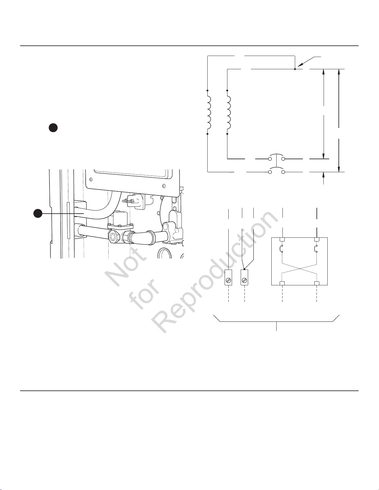
Système de branchement C.A. de la génératrice
Not
for
Reproduction
Un système de branchement C.A. monophasé à trois fils est
utilisé pour le groupe électrogène. L’assemblage du stator est
constitué d’une paire de bobines stationnaires à deux bornes
sortant de chaque bobine. La jonction des fils 22 et 33 forme
le fil neutre, tel qu’illustré au moyen du dessin et du schéma
de câblage suivant. Vous trouverez un dessin et un schéma
de câblage dans le manuel de listes de pièces illustrées.
AVIS Le neutre n’est pas raccordé à la terre au niveau de
la génératrice.
Le conduit
de commande est une exigence d’UL. S’il est retiré, il doit être
remplacé par un conduit similaire.
A
entre l’entrée électrique de coin et le tableau
A
33
22
Enroulement de puissance
11
44
Neutre
120V
120V
Disjoncteur
240V
1122 33 440
Mise à la masse de la génératrice
Le groupe électrogène résidentiel doit être mis à la
masse en conformité avec tous les codes, normes et
réglementations applicables. La languette de contact de
mise à la masse (GND) de la génératrice est située dans le
panneau de commande de la génératrice, sous le couvercle
des disjoncteurs.
Mise à la terre
Disjoncteur
Neutre
Vers le commutateur de transfert
Ligne 2
Ligne 1
91
Page 92

Interconnexions du circuit de commande
Not
for
Reproduction
Des fils de 240 V doivent être passés dans le conduit.
L’alimentation de 240 V procure l’alimentation de service à la
carte de circuit de la génératrice, la batterie en option et le
chauffe-huile, recharge la batterie et la génératrice démarre
en cas de panne électrique.
À l’aide du connecteur à 2 pôles fourni et d’un fil de cuivre
d’au moins 300 V, 14 AWG, fourni par l’installateur, raccordez
chaque terminal du circuit de la génératrice de commande
au commutateur de transfert automatique.
Communication du commutateur de transfert
(Unités avec un ACCM II ou un plus défunt tableau de
commande seulement).
En utilisant deux conducteurs torsadés de calibre 18, pas
plus de 60 m (200 pieds) de long, raccordez Tx Rx et Tx Rx
GND à partir du tableau de commande A de la génératrice
aux bornes T/R et GND du module de commande
commutateur de transfer
tension
C
.
t par l’ouverture d’accès basse
du
B
Lorsque vous établissez des raccordements électriques,
respectez les spécifications relatives au type de fil et au
serrage se trouvant sur le disjoncteur et le raccord neutre/de
mise à la terre.
A
Système de détection des pannes
Le tableau de commande de la génératrice est doté d’un
affichage numérique pour indiquer les codes de défaillance. Il
affiche un code de défaillance lorsque certaines défaillances
sont décelées dans le groupe électrogène. Une autre DEL et
une plaque de montage sont fournies pour leur installation
à l’intérieur dans un endroit pratique. Pour obtenir des
renseignements plus détaillés, consultez la section Système
de détection des pannes du manuel d’utilisation.
Elles permettent au propriétaire d’observer l’état du groupe
électrogène. Si certains problèmes sont détectés dans le
groupe électrogène, le voyant DEL à distance clignotera
un certain nombre de fois. Consultez le propriétaire pour
convenir d’un endroit pratique. Placez la boîte électrique
dans un endroit visible par le propriétaire tel que près d’un
ouvre-porte de garage ou d’un panneau de commande
de sécurité.
C
B
Pour installer le panneau DEL à distance du
groupe électrogène :
1. Poussez la DEL à travers la plaque de montage par
l’avant jusqu’à ce qu’elle se fixe d’un coup sec. Le
voyant DEL est sensible à la polarité.
2. À l’aide du connecteur à 10 pôles fourni et d’un fil de
calibre minimal de 18 AWG fourni par l’installateur,
branchez la DEL à distance aux connecteurs +LED
et GND du tableau de commande de la génératrice.
Utilisez des serre-fils pour raccorder le fil aux
conducteurs de la DEL.
3. Fixez la plaque de montage au coffret électrique à
faible tension fourni par l’installateur.
92
Page 93

Système de détection des pannes
Not
for
Reproduction
La génératrice fonctionnera sans doute pendant de longues
périodes sans la présence d’un opérateur. C’est pourquoi le
système est muni de capteurs qui arrêtent automatiquement
la génératrice lorsque surviennent des problèmes potentiels,
tels une faible pression de l’huile, une température élevée,
l’emballement du moteur et d’autres conditions. Pour obtenir
des renseignements plus détaillés, consultez la section
Système de détection des pannes du Manuel d’utilisation.
Tableau de commande du système
Le tableau de commande du groupe électrogène, situé à
l’intérieur du bâti de la génératrice, est illustré ci-dessous.
Voici une brève description des commandes utilisées
durant l’installation:
DBEC F
A
A
– SET EXERCISE (Réglage du cy
pour régler l’heure de démarrage du cycle d’exercice.
- Disjoncteur ― Doit êtr
B
commutateur de transfert. Le boîtier du disjoncteur
comprend un panneau inférieur amovible qui facilite les
raccordements de conduits.
- Fusible de 15 ampères ― Protège les circuits de
C
commande C.C. de la génératrice résidentielle. Si le
fusible est grillé (fondu et ouvert) ou a été enlevé, le
moteur ne peut être lancé ou démarrer. Remplacez le
fusible grillé uniquement par un fusible ATO de 15 A. Un
fusible de rechange est fourni avec l’unité. Si le fusible
est grillé ou a été enlevé, vous devrez réinitialiser la
minuterie d’exercice (voir Réglage de la minuterie de
cycle d’exercice).
e à ON pour alimenter le
cle d’exercice) – Utilisé
- Interrupteur du système ― L’interrupteur de système
D
constitue la commande la plus importante de la
génératrice. Dans le présent document, ce dispositif à
deux positions et s’utilise comme suit:
• La position normale de fonctionnement est la position
“AUTO”. Si une panne d’électricité est détectée,
le système démarrera la génératrice. Lorsque
l’électricité est rétablie, laissez le moteur stabiliser
les températures internes, fermez la génératrice et
attendez la prochaine panne d’électricité.
• La position “OFF” ferme la génératrice quand elle
fonctionne, ce qui empêche l’unité de démarrer et de
remettre à zéro toute détection de panne.
– MANUAL OVER-RIDE (S
E
pour démarrer et arrêter manuellement la génératrice.
F
- Écran numérique ― Affiche le temps de
fonctionnement en heures ou les codes de défaillance.
Consultez la section Commandes du manuel d’utilisation
pour de plus amples renseignements.
urpassement manuel) – Utilisé
93
Page 94

Dalle en béton (en option)
Not
for
Reproduction
Si le code local exige une telle dalle, coulez une dalle de
béton mesurant au moins 3 pouces (76 mm) d’épaisseur et
6 pouces (152 mm) plus long et plus large que l’unité ellemême (34.6 in (880 mm) x 39.4 in (1000 mm)). À l’aide de
boulons d’ancrage de maçonnerie de 1/4 po (0,64 cm) de
diamètre (au minimum) et suffisamment longs pour retenir
l’unité, fixez l’unité à la dalle.
Percez des ouvertures de boulon d’encrage à la base de
l’unité aux quatre endroits recommandés
Mesures de l’emplacement de perçage pour boulons
d’ancrage
A
B
C
D
5.51 in (140 mm)
23.62 in (600 mm)
16.78 in (426.4 mm)
2.55 in (65 mm)
.
F
B
23.62 in
(600mm)
5.51 in
140
(140mm)
A
F
1/4 in
F F
(6mm)
5.51 in
(140mm)
1.57 in
40
(40mm)
E
16.78 in
426.4
(426.4mm)
C
F
140
A
2.55 in
(65mm)
D
E
F
1.57 in (40 mm)
1/4 in (6 mm) holes
La Base de gravier (facultatif)
Si a rendu obligatoire par le code local, éclaircir
un secteur approximativement cinq pouces profonds et à peu près six pouces plus large qui les
caractères de pied du générateur d'état d'attente.
Revêtir le secteur avec le fi lm de polyuréthane et
remplir avec le gravier de pois ou la pierre écrasée.
Compact et niveler la pierre. Si la dalle concrète est
exigée, voit la section de Dalle Concrète dans ce
manuel.
94
Page 95

Considérations pour l’installation finale
Not
for
Reproduction
Huile à moteur
AVIS Toute tentative de démarrer le moteur avant qu’il ait
été rempli avec l’huile recommandés entraînera une panne
de l’équipement.
• Consultez la section Entretien des manuels d’utilisation et du
moteur au sujet du remplissage de l’huile.
• La garantie sera annulée si des dommages à l’équipement sont
entraînés par le manquement à se conformer à cette directive.
Ce moteur a été testé en usine et est livré rempli d’huile non
synthétique (API SJ/CF SAE 5W-30). Cela permet au système
de fonctionner dans une plage élargie de températures et de
conditions climatiques. Avant de démarrer le moteur, vérifiez
le niveau d’huile tel que décrit dans la section Entretien du
manuel d’utilisation.
L’utilisation de l’huile synthétique ne modifie aucunement
les intervalles de changement d’huile recommandés dans le
manuel d’moteur.
Batterie
L’installateur doit fournir et installer une batterie de
démarrage de 12 volts C.C. rechargeable à régulation par
soupape. La batterie de démarrage DOIT être conforme aux
spécifications indiquées dans ce tableau.
Spécifications de la batterie
Volts 12 volts CC
A (MIN) 600 CCA (ampérage de démarrage
à froid)
Type AGM
Matériel délimitant M6
Dimension (MAX) :
Largeur 5.5 pouces (140 mm)
Longueur 9.0 pouces (200 mm)
Hauteur 5.25 pouces (210 mm)
Installez la batterie de la façon décrite à la rubrique
Entretien de la batterie de la section Entretien du manuel
d’utilisation. Assurez-vous que le câble NÉGATIF est branché
en dernier lieu et que l’isolateur de borne rouge POSITIF est
bien en place.
AVERTISSEMENT Les bornes, les cosses ainsi que tous les
accessoires reliés à la batterie contiennent du plomb et des
composés de plomb - produits chimiques reconnus par l’État de la
Californie comme causant des cancers et d’autres problèmes de
reproduction. Nettoyez-vous les mains après la manipulation.
AVERTISSEMENT Les batteries d’accumulateur produisent
du gaz hydrogène explosif lorsqu’elles
se rechargent.
La plus petite étincelle enflammera
l’hydrogène et provoquera une explosion.
Le liquide d’électrolyte de l’accumulateur contient de l’acide et est
extrêmement caustique.
Le contact avec le liquide de l’accumulateur provoquera de graves
brûlures chimiques.
Toute batterie présente un risque de choc électrique et de courant
de court-circuit élevé.
• NE jetez PAS la batterie dans un feu. Recyclez la batterie.
• Ne laissez aucune flamme, étincelle, source de chaleur ou
cigarette allumée pendant ou plusieurs minutes suivant la charge
de l’accumulateur.
• N’ouvrez PAS ni N’endommagez la batterie.
• Portez des lunettes de sécurité ainsi qu’un tablier, des bottes et
des gants en caoutchouc.
• Enlevez votre montre, vos bagues et tout autre objet de métal.
• Utilisez des outils avec des poignées isolées.
95
Page 96

Démarrage initial (sans charge)
Not
for
Reproduction
L’unité a été configurée en usine pour fonctionner au gaz
naturel. La conversion de combustible, doit être effectuée
avant de suivre ces étapes (voir Conversion du combustible).
Avant d’utiliser ou de mettre en service le groupe
électrogène, vérifiez minutieusement l’ensemble de
l’installation. Commencez ensuite des essais du système
sans aucun branchement de charges électriques, comme
indiqué ci-dessous:
1. Retirez les quatre vis
commande au boîtier pour exposer le disjoncteur
de l’
appareil.
A
A
2. Branchez un fréquencemètre précis du côté charge
du disjoncteur principal de la génératrice.
3. Réglez le disjoncteur principal de la génératrice sur sa
position ON.
4. Réglez l’interrupteur de système de la génératrice
sur OFF.
ATTENTION L’installation du fusible pourrait causer le
démarrage du moteur.
A
qui fixent le panneau de
A
A
Pour le démarrage initial du groupe électrogène, il faut
purger l’air contenue dans les canalisations de combustible.
Cela peut nécessiter quelques minutes.
8. Écoutez s’il y a des bruits ou vibrations inhabituels
et soyez attentif à tout signe de fonctionnement
anormal. Vérifiez s’il y a des fuites d’huile pendant que
la génératrice fonctionne.
9. Laisser le moteur se réchauffer durant cinq minutes
environ afin de permettre à sa température interne de
se stabiliser.
10. Vérifier la tension devrait être de 239 à 262 volts, et
la fréquence devrait être de 62,0 à 62,5 Hz.
Si un de ces paramètres est à l’extérieur de ces plages,
effectuez les Réglages du moteur.
11. Vérifiez la tension de sortie de la génératrice entre
une des languettes de contact generator connection
et la languette de contact neutre, puis entre l’autre
languette de contact de la generator connection et
la languette de contact neutre. Dans les deux cas, la
lecture de la tension de sortie devrait se situer entre
119 et 131 volts.
NE PAS procéder avant d’être certain que la tension C.A.
et la fréquence de la génératrice sont conformes et se
trouvent dans les limites stipulées. Pour obtenir la fréquence
appropriée de la génératrice, voir Réglages du moteur.
12. Poussez et tenir MANUAL OVER-RIDE jusqu’ aux
arrêts de moteur.
13. Replacez le tableau de commande dans le boîtier.
• Prenez note que, avant l’expédition, le fusible de 1 Ampères a été
retiré du panneau électrique.
• N’installez PAS ce fusible avant que toute la plomberie et le
câblage n’aient été complétés et vérifiés.
5. Installez le fusible de 15 Ampères dans le
panneau électrique.
6. Réglez l’interrupteur de système de la génératrice
sur AUTO.
7. Maintenez le bouton MANUAL OVER-RIDE du tableau
de commande enfoncé pendant six secondes.. Le
moteur devrait s’arrêter.
96
Page 97

Réglage du moteur
Not
for
Reproduction
Il est bien connu que la combustibilité du gaz naturel varie
d’une région à l’autre. Chaque unité est réglée en usine pour
fonctionner adéquatement avec le gaz naturel. Si la tension
de sortie ou la fréquence de la génératrice mesurée au
cours de la Vérification initiale, s’écarte des plages indiquées,
il se peut que la combustibilité du gaz fourni au site de
l’installation soit très différente.
Pour régler le moteur en fonction de ce combustible
différent, procédez comme suit:
1. Retirez les quatre vis qui fixent le panneau de
commande au boîtier pour exposer le disjoncteur
de l’appareil.
2. Branchez un fréquencemètre précis du côté charge
du disjoncteur principal de la génératrice.
3. Assurez-vous que le fusible de 15 Ampères est
en place.
4. Réglez le disjoncteur principal de la génératrice
sur ON.
5. Réglez l’interrupteur de système de la génératrice
sur AUTO.
6. Poussez MANUAL OVER-RIDE (surpassement manuel)
sur le tableau de commande. Lorsque le moteur
démarre, laissez-le se réchauffer durant cinq minutes.
7. La fréquence sans charge normale est de
62,0 à 62,5 Hz. Lorsqu’un ajustement est requis sans
charge, retirez les panneaux latéraux de l’unité. À
l’aide de pinces à becs fins, pliez lentement le tenon
d’ancrage à ressort
ce que la fr
équence soit entre 62,0 et 62,5 Hz.
A
vers le haut ou le bas jusqu’à
8. Mettez hors tension l’interrupteur de l’alimentation
de service vers le commutateur de transfert.
Le commutateur de transfert se branchera à la
génératrice après un court délai.
9. Chargez la génératrice à la charge maximum.
10. Branchez un fréquencemètre précis du côté
charge du disjoncteur principal de la génératrice. La
fréquence devrait être supérieure à 57,0 Hz.
11. Si la fréquence est inférieure à 57,0 Hz, tournez
lentement la vis de réglage du régulateur dans le sens
horaire jusqu’à ce qu’elle dépasse 57,0 Hz.
12. Mettez sous tension l’interrupteur de l’alimentation
de service vers le commutateur de transfert.
Le commutateur de transfert se branchera à
l’alimentation de service après un court délai.
13. Poussez MANUAL OVER-RIDE (surpassement
manuel) sur le tableau de commande jusqu’ aux
arrêts de moteur.
14. Lorsque le moteur est arrêté,
• Qu’un réglage a été effectué à l’étape 11, effectuez
de nouveau les étapes 2 à 7.
• Si un réglage n’a pas été effectué à l’étape 11,
passez à l’étape 15.
Si la fréquence sans charge chute en deçà du
paramètre sans charge après qu’un réglage de pleine
charge est effectué, communiquez avec un centre de
service autorisé.
15. Replacez le tableau de commande dans le boîtier.
A
97
Page 98

Fonctionnement
Not
for
Reproduction
Séquence de fonctionnement automatique
Le panneau électrique de la génératrice contient une
carte de circuit logique de commande. Ce tableau de
commande contrôle constamment la tension de l’électricité
de service. Si cette tension baisse sous un niveau prédéfini,
le tableau de commande signalera le lancement et le
démarrage du moteur.
Lorsque la tension de service est rétablie au-delà d’un niveau
de tension préétabli, le moteur reçoit un signal d’arrêt.
Le fonctionnement actuel du système ne peut être modifié,
et il est séquencé par des capteurs et des minuteries du
tableau de commande de la manière suivante:
Capteur de désexcitation de la tension de l’alimentation
de service
• Ce capteur contrôle la tension de l’alimentation
de service.
• Si la tension baisse sous 70% de la tension
d’alimentation nominale, le capteur amorce un
décompte de 10 secondes. Le décompte sert à
identifier les pannes de courant localisées.
• Lorsque le décompte est expiré, le moteur est
lancé et démarre.
Capteur de prise en charge de la tension de service
Ce capteur supervise la tension d’alimentation de service.
Lorsque cette tension est rétablie à 80 pour cent de la
tension nominale source, un délai est déclenché et le moteur
entrera en mode refroidissement du moteur.
Minuterie de refroidissement du moteur
• Lorsque la charge est transférée à nouveau à la
source d’alimentation de service, la minuterie de
refroidissement du moteur s’active.
• Environ une minute s’écoule avant l’arrêt
de la génératrice.
• Le moteur tourne durant au moins 5 minutes.
98
Page 99

Réglage de la minuterie de cycle d’exercice
Not
for
Reproduction
Le groupe électrogène est muni d’une minuterie de cycle
d’exercice ui se met en marche et vérifie le système une
fois par semaine. Au cours de ce cycle d’exercice, l’unité
fonctionne durant une douzaine de 20 minutes, puis s’arrête.
Le transfert de charge électrique N’A PAS lieu durant le cycle
d’exercice (sauf si une panne de courant survient).
Un bouton du tableau de commande est étiueté « Set
Exercise » (voir Tableau de commande du système). Le jour
et l’heure particuliers auxuels ce bouton est pressé sont
programmés dans la mémoire du tableau de commande.
Ce jour et cette heure sont alors utilisés pour initialiser
automatiquement le cycle d’exercice du système. La légende
« SET EXERCISE » du tableau de commande clignote jusu’à
ce ue le cycle d’exercice soit réglé.
Pour exécuter la procédure de réglage du cycle d’exercice:
1. Choisissez le jour et l’heure à lauelle vous désirez ue le
cycle d’exercice du groupe électrogène ait lieu.
2. À cette journée et heure, appuyez et maintenez
enfoncé l’interrupteur “Set Exercise” pendant
trois secondes.
Le “Set Exercise” l’affichage illuminera alors éteint
pour confirmer que le minuteur d’exercice a été réglé.
Alors relâcher le bouton Fixe d’Exercice.
L’unité coudera et courra le cycle d’exercice. Pendant
le cycle, Régler l’Exercice illuminera.
Une fois le cycle d’exercice est complet, l’unité
éteindra et “Set Exercise” fera non plus long est
affiché.
Le cycle d’Exercice pourrait être interrompu à
n’importe quand en tournant le Commutateur de
Système à LOIN.
3. L’unité s’amorcera puis entreprendra son cycle
d’exercice de 20 minutes.
Par exemple, si vous appuyez « SET EXERCISE » de réglage
du cycle d’exercice le dimanche à 10 h, l’unité exécutera un
cycle d’exercice puis fera de même tous le dimanche matin
à 10 h (+/- ½ heure).
Le réglage du cycle d’exercice ne fonctionnera que si l’unité
est en mode AUTO et que si la procédure exacte est suivie.
Vous devrez reprogrammer le cycle d’exercice si vous
enlevez ou remplacez le fusible de 15 A ou si la batterie de
demurrage est débranchée.
Si vous voulez changer le jour et l’heure du cycle d’exercice,
vous n’avez qu’à exécuter à nouveau la procédure de
Réglage de la minuterie du cycle d’exercice le jour et
à l’heure exacte à laquelle vous voulez que le cycle
d’exercice ait lieu.
La génératrice n’exécutera pas le cycle d’exercice, si la
minuterie n’est pas réglée.
Vérification installation
Avant de mettre en service le groupe électrogène, vérifiez
minutieusement l’ensemble de l’installation.
Cela met fin aux directives d’installation et de démarrage.
Le manuel d’utilisation renferme des explications
détaillées sur l’utilisation, l’entretien et le dépannage de ce
groupe électrogène.
99
Page 100

Not
for
Reproduction
est une marque de commercede la société General
Electric Company et est utilisée sous licence par
Briggs & Stratton Power Products Group, LLC.
Copyright © 2011. Tous droits réservés. Aucune partie de ce manuel ne peut
être reproduite ou transmise sous n’importe quelle forme sans l’autorisation
expresse écrite de Briggs & Stratton Power Products Group, LLC.
Manual No. 312760GS Rev. B
 Loading...