

Page 1

Communications
System Analyzers
The New R2600 Series, including R2600, R2625 and R2670
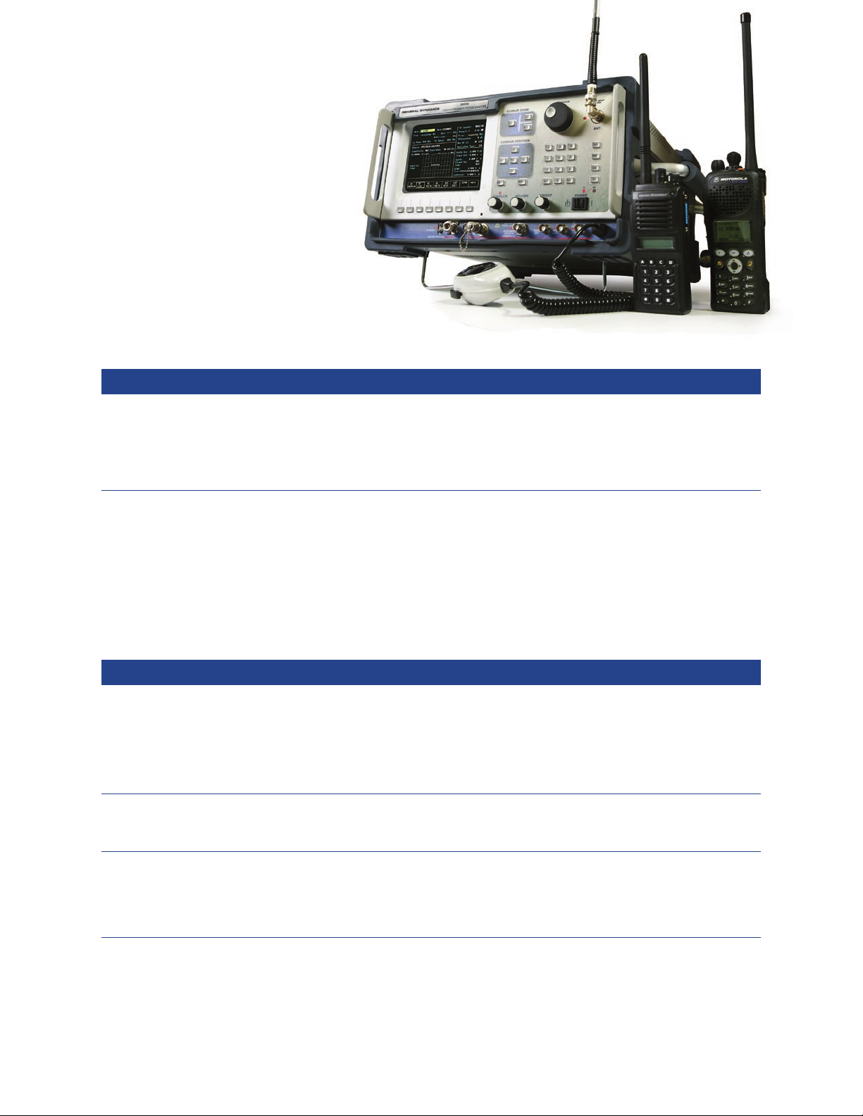
If you maintain, repair, calibrate, or design radio
communications equipment, the R2600 family of
Communications System Analyzers has a solution for
you. Rugged enough to withstand heavy field use,
the R2600 is designed to help you save time and work
more efficiently. This platform is available in three models,
each tailored to its own set of testing requirements.
Page 2

Features/Benefits
1) Display Zone for presentation of test data
and waveforms
2) RF Control Zone for selecting RF test conditions
3) Cursor Zone keys provide simple, one-button
access to any zone
4) Tuning Knob for quick and easy changes of numeric
entries: Digital precision with an analog feel
5) Off-the-air antenna port for sensitive receiver
measurements
6) Color LCD
7) VGA output port
8) High speed serial port for remote control
operation and flash software update capability
9) User-friendly, soft-touch keys for feature selection
10) Audio Control Zone for setting modulation
conditions
11) Cursor position keys allow instant cursor
movement within a zone
12) Memory recall for up to 30 channels including
automatic scanning plus optional 15 user programmable test setups
13) One-button access to special functions
14) Hard rubber bumpers on front and rear for
maximum physical integrity
15) Rubberized knobs
The R2600 Series: The industry proven test solution
for APCO™ Project 25 (Project 25) SMARTNET/
SmartZone™, ASTRO™, SECURENET™, and
conventional two way radio.
The R2600 family of Communications System Analyzers
performs tests normally associated with these instruments:
• RF Signal Generator
• Sensitive Measurement Receiver
• Spectrum Analyzer
• Full Band Duplex Offset Generator
• Frequency Counter
• AC/DC Voltmeter
• 50 kHz Oscilloscope
• RF Wattmeter
• Signal Strength Meter
• Frequency Error Meter
• SINAD Meter
• Distortion Meter
• Sweep Generator
• Audio Generator
• Modulation Analyzer
• Signaling Simulator
• RF Scan/Counter
• High Performance Spectrum Analyzer with Markers
Optional in R2600 & R2625; standard in R2670:
• Cable Fault Locator
• Tracking Generator
• Programmable Test Set-Ups
2
Page 3

The R2600 family has a solution for your radio communication testing needs
R2600 – For Conventional
Radio and Base Station Service
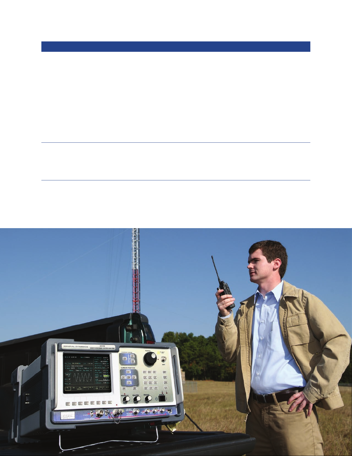
If you service conventional two-way
systems, the value-packed R2600 is
the product for you.
Because of its unique design, the
R2600 allows you to perform
numerous complex functions with
the same piece of equipment. This
“one-box” design is especially
useful in remote sites or where
use of multiple pieces of heavy
equipment is impractical – or
impossible.
R2625 – Economical
Project 25 Solution
The most cost-effective Project
25 test solution on the market, the
R2625 is specifically configured
for the needs of those servicing
Project 25 along with conventional
two-way analog systems.
In addition to all of the test
capabilities of the R2600, the
R2625 comes standard with DESOFB Project 25 compatible Type
III encryption. The R2625 also
contains Project 25 diagnostic test
capability, and can be optionally
expanded to include the following:
• Tracking Generator
• Cable Fault Testing
• Programmable Test Set-Up Memory
• Project 25 compatible Type
III AES Encryption
• Project 25 Trunking
Advanced Project 25 Test and Diagnostics
Error Vector Magnitude
The CM 816 Error Vector Magnitude
(EVM) application provides a
constellation diagram that gives a
clear, visual picture of how close the
measured signal aligns with an ideal
reference. It works with C4FM,
CQPSK, and LSM modulation
types, and includes a user-definable
tolerance setting which allows the
operator to quickly visualize the
performance under test.
The Software also generates a
histogram distribution of the EVM
metrics, providing another form of
visual analysis of the transmitter’s
performance over time.
The CM816 EVM option can be
used with any R2625C model
analyzer or R2670B equipped
with the CM801 enhanced digital
hardware module and CM813
Project 25 option.
Channel Logging
The CM815 P25 Channel Logging
option provides P25 Common Air
Interface data. This includes Data
Unit type and a breakdown of the
various message and value fields
as defined by the P25 standard.
Logging data is described with
meaningful names - i.e. an
ALGID of 0x80 will be shown as
“Un-encrypted”. Additionally,
message timing is provided with
each sent and received message –
especially important when working
with P25 Trunking.
For a lower level analysis of radio
R2670 – Expandable Platform
for Digital, Trunked, and
Secure Testing
In addition to having all the
capabilities found in the R2600,
the R2670 FDMA digital
Communications System Analyzer
is a special digital hardware
platform that allows
customized configuration to include
multiple test capabilities in one
convenient package.
R2670 OPTIONAL test capabilities:
• SMARTNET/SmartZone
Type I, I EP II, II
• Project 25 Standard
Conventional
(IMBE) and Encrypted
• ASTRO Conventional (VSELP)
and Encrypted
• R2680-MPT1327/1343 Test
Solution
performance the symbols that are
sent and received are logged and
can be saved and recalled for later
analysis. The Channel Logging PC
application also provides a f ilter that
allows the user to show only what is
relevant to the task at hand.
3
Page 4

AutoTest/AutoTune
For Digital / P25 Equipped Radios
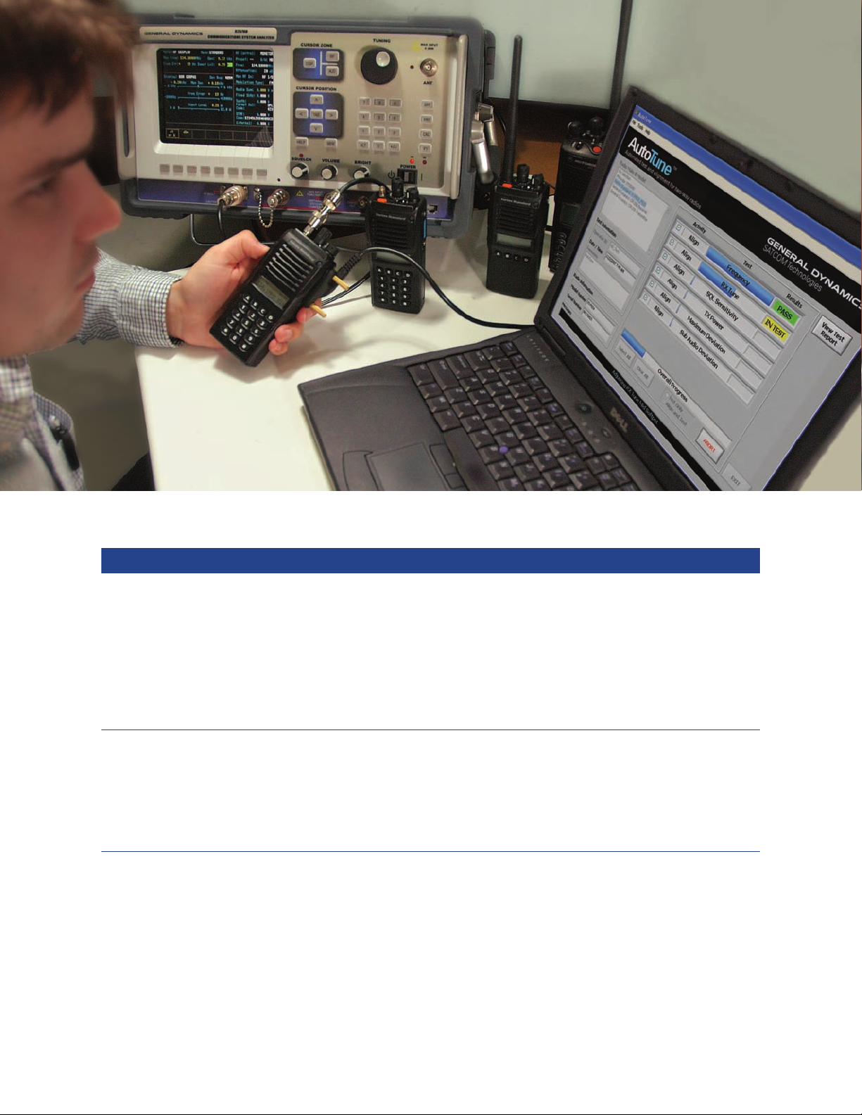
Automated Test and Alignment
AutoTest and AutoTune perform all
recommended factory alignment procedures
and critical transmitter/receiver performance
tests – in a fraction of the time it takes to
perform manually.
Fast, accurate, easy to use
The AutoTest and AutoTune software
applications takes the guesswork out of
aligning your radios. Simply connect the
radio, select the tests and/or alignments you
wish to perform from the menu, and press
“Run.” The software automatically “reads”
the radio’s internal programming, configures
the analyzer, and takes measurements
as needed. If required, internal radio
adjustments are then automatically performed
to bring the radio into proper alignment. All
measurement results and initial/final softpot
settings are stored for easy retrieval.
Now even non-technical personnel can
fully test and align your radios – freeing
technicians to do actual repairs.
4
Page 5

R2625/R2670*
Analyzer
Computer
AutoTest System Configuration
*P25 conventional equipped R2670
Motorola
Radio
Benefits/Features
Significantly Reduced Test Times
• A typical radio alignment can be completed in less
than 10 minutes.
• Program automatically “reads” the radio’s parameters
and configures the analyzer to significantly reduce
operator intervention.
• Pass/Fail indication reveals defective radios.
Easy to Use
• Standard Windows® interface makes AutoTest simple
and intuitive to operate.
• No technical expertise required.
• All results are automatically saved to disk and can
be viewed and printed at any time.
Accurate and Repeatable Results
• Utilizes the R2670 or R2625 Communication Systems
Analyzer for dependable performance.
• Alignments and performance tests are performed
according to manufacturer’s specifications.
• Allows consistent alignment from radio to radio.
Tests/Alignments Performed
Alignments
• Reference Oscillator
• Transmitter
Deviation Balance
• Transmitter
Deviation Limit
Transmitter Tests
• Bit Error Rate (BER)
• Reference Frequency
• RF Output Power
Receiver Tests
• Rated Audio
• Distortion
• SINAD Sensitivity
• Noise Squelch
• Voice Modulation, External
• Voice Modulation, Internal
Minimum Requirements for
Communications System Analyzer
Model Required options Firmware
R2670A/B CM701/CM713 or CM801/CM813 V6.08
R2625A/B/C None V6.08
Ordering Information
Radio Model Number AutoTest/AutoTune Part
XTS3000 RVN5012B
XTS5000 RVN5013B
XTS3000/5000 RVN5016B
ASTRO SPECTRA RVN5024B
ASTRO SPECTRA PLUS RVN5025B
ASTRO SPECTRA/ SPECTRA PLUS RVN5026B
AUTO TEST SUITE RVN5027B
(includes RVN5016B & RVN5026B)
Vertex Standard VX-P820/920 202621-01
5
Page 6
Standard System Features
Feature Benefits
High Performance Spectrum Analyzer
The built-in High Performance Spectrum Analyzer will display a
window of RF spectrum anywhere within the 400 kHz to 1 GHz
operating range of the unit. The EXPAND softkey enlarges the display
to fill the LCD and retains dispersion and center frequency control.
The High Performance Spectrum Analyzer adds Marker functions for
more precise measurements of level and frequency (both absolute and
delta). Included with the marker functions are additional dispersion
selections – up to 10 MHz per division, plus the additional freeze,
peak hold, and max hold features.
Terminated RF Wattmeter
RF power anywhere in the operating range of 400 kHz to 1GHz is
automatically measured by the Communications System Analyzer
when tuned to that frequency. The built-in RF load dissipates up to
125 watts for one minute.
If a high power transmitter should be keyed into the unit for any
longer, the LCD changes to read “WARNING RF OVERLOAD,”
thus warning the technician to un-key.
Programmable Test Memory
Channel Presets – The unit has 30 memory locations which can be used
to store preset channel information. Channels can readily be selected
individually or automatically scanned over a user-defined range.
Programmable Test Setups (standard in R2670; optional in R2600
and R2625) – You can easily program and store up to 15 of the most
commonly used test configurations, including all test conditions,
measurement display formats, and levels. These memory settings
operate independently of the channel presets.
The ability to observe the spectrum display for detailed analysis
through the use of multiple Markers provides a significant advantage.
The tuning knob retains control of the center frequency even in the
EXPAND mode to perform fast sweeps or fine tuning. This allows
you to quickly locate and identify signal carriers.
This feature provides calibrated RF power measurements eliminating
the need for a separate wattmeter. The LCD also displays frequency
error and modulation level readings simultaneously.
Channel Presets – This feature allows quick access to frequently used
channel location information to speed testing. Scanning allows automatic
monitoring and measurement of activity on channels of interest.
Programmable Test Setups (standard in R2670; optional in R2600
and R2625) – You can significantly reduce the number of key presses
required to set up more commonly used test configurations, greatly
increasing your efficiency while promoting uniform test procedures.
You can also assign a custom name to the configuration for easy recall.
6
Page 7

Standard System Features – continued
Feature Benefits
Relative Signal Strength Meter
In addition to reading frequency error and modulation, a digital readout
relative signal strength meter has been included. Sensitivity is specified
to -100 dBm at the antenna port for FM signals and extends up to 125
watts at the RF I/O port. The LCD display will automatically convert
to a terminating “watts” display as the level increases.
This feature, in conjunction with an external antenna, allows remote
monitoring of distant transmitters to check for antenna, transmission
line or P.A. problems. Many users also f ind this feature convenient in
performing propagation studies to identify weak coverage areas.
RF Scan / RF Counter Function
RF Scan operates in the monitor mode and provides a function
similar to a 1 GHz counter. This feature automatically scans a
user-defined frequency range and locks on the applied signal. Any
RF carrier above 20 MHz can be located within 5 seconds and the
reception displayed with digital readouts.
Duplex
Full output level control from -130 dBm to 0 dBm over the entire range
of the instrument is available from the RF I/O port (-130 dBm up to
-50 dBm) and the generator port (-80 dBm to 0 dBm). Variable offsets
from 0 to ±999.995 MHz in 2.5 kHz steps are keypad-selectable.
Tracking Generator (standard in R2670; optional in R2600 and R2625)
The combining of the capabilities of the sweep generator and the
spectrum analyzer into a Tracking Generator function allows the user
to view the performance characteristics of many RF f ilter devices.
Display range is operator selectable from a 200 kHz window up to a
50 MHz window anywhere in the 400 kHz to 1GHz spectrum.
Signaling Simulator: Encoder and Decoder
The System Analyzer includes the capability of encoding and decoding
PRIVATE LINE (PL), DIGITAL PRIVATE LINE (DPL), and single
tone sequences as well as multi-tone sequences including DTMF
signals, 5/6 tone paging, Select V and up to 20 sequential tones.
Decoding displays include tone frequencies and time durations of the
individual tones. The unit can also encode tone remote signaling.
This feature allows convenient and immediate verification of the
programming of a multi-channel radio. By automatically tuning the
analyzer’s receiver to the detected carrier, immediate measurement
data can be taken without having to enter new frequency data
via the keyboard.
The duplex generator provides enhanced capability to service
equipment, such as repeaters and full duplex radios. Full RF level
control, as well as full internal and external modulation capability
allows receiver desensitization and transmitter tests to be performed
simultaneously through one port, if desired.
The wide offset range extends the functionality to include cross
band repeater systems, as well as enhanced receiver and transmitter
troubleshooting capabilities.
Diagnosis and adjustment of critical receiver front ends, IFs, helical
filters, cavities, combiners and duplexers can be made in a few
minutes, quickly and easily with the flexibility of a tracking generator
at your fingertips.
The signaling capability of the unit reaches a broader range of
service applications with its decode capability. This gives you a more
flexible test instrument which aids in servicing paging equipment and
specialized signaling encoders, as well as mobile, portable and other
radio products. The signaling simulator can perform a full system
check-out faster, with more accuracy than ever before.
General Purpose & Modulation Oscilloscope
The oscilloscope has a 50 kHz bandwidth for audio waveform
analysis. The display can be triggered over the full screen range to a
fixed reference level. Triggering in both automatic and normal modes
is provided for synchronizing the horizontal timebase to the vertical
input signal. Internal or external inputs allow observation of both
generated and monitored modulation signals. Softkeys provide for an
enlarged full screen display.
Flash Upgradable Software
High-Speed serial port and flashable memory permit programming
firmware updates from an external PC.
Cable Fault (standard in R2670; optional in R2600 and R2625)
Cable fault and length are RF measurement features which help the
technician isolate cable defects. Supported by on-screen prompts and
user-selectable Help messages, you can quickly set up and accurately
determine the distance to a fault on a coaxial cable. The distance to
fault (or cable length) is computed and displayed in feet or metric units.
RS-232/Serial Interface (standard) IEEE-488-2 Interface (optional)
A full bi-directional RS232 port is standard and includes the capability
to respond to serial input command vocabulary and return measurement
results as a serial output stream. Included are user-selectable baud rates
(up to 115.2 Kbps) and start, stop and parity bit selection. In addition,
this dual function port can drive a serial printer to print out data and
graphic displays. The optional IEEE remote interface option contains
the necessary hardware and software for IEEE-488.2.
Recovered audio or internally produced audio can be displayed
visually for deviation measurements. Additionally, detection of an
asymmetric modulation or audio distortion can be achieved with
waveform analysis. With internal and external triggering and a freeze
display single sweep, this unit duplicates many features of more
expensive scopes. The markers allow detailed analysis to measure
waveforms displayed on the LCD. The EXPAND function provides an
enlarged, easy to interpret view of the signal for quick analysis.
Quick and easy access to future software updates.
Cable fault locating techniques are mandatory for site servicing,
where visual inspection is not practical, safe, or effective in detecting
hidden or cold-flow damage. The semi-automatic operation of the
cable faultfinder precludes the use of mathematical formulas and
manual calculations, maximizing your on-site productivity.
If you have large volume repetitive testing requirements, this feature
allows you to write your own programs to reduce test time costs.
Printed results can be used as part of the service shop’s internal
quality control system and can be used to demonstrate performance
to the radio equipment user.
7
Page 8
SMARTNET/SmartZone
(Available on R2670 only)
Feature Benefits
Dynamic Call Testing of Subscriber Radios
This feature tests Motorola compatible Type I, Type II, SmartZone
and ASTRO IMBE/VSELP trunked mobile and portable radio units
under actual signaling conditions. This is achieved by simulating the
function of the trunked fixed-end equipment. The radio access control
channel is provided to perform initial registration. A thermometerstyle graphic indicator shows call progression as it directs the radio
to a traffic channel for parametric measurements and voice testing.
Radio-initiated or system-initiated tests can be performed in either
the phone interconnect or dispatch call modes. Dynamic Call Testing
allows you to test auto affiliation for SMARTZONE systems.
An additional RF synthesizer provides simultaneous control and traffic
channels, operator selectable over the entire band of allowable channels.
This option also allows you to exit from the main testing screen while
a call is in process to access the other diagnostic screens.
Closed Cover Measurements
Transmitter power, frequency and deviation are measured within the
dynamic calling mode and displayed on the signaling screen all with
a single RF connection to the radio. Additional measurements can be
made on other screens while the simulated “live” call is maintained.
Radio ID information is decoded in either hex or decimal format.
Dedicated Trunking Screens
Conveniently accessed, dedicated test screens can be set up as a
start-up default condition or a programmable test set-up. Dedicated
Trunking test screens are windowed with RF and Modulation control
screens to simultaneously display test results along with their test
conditions. A single system configuration screen for Type I systems
provides non-volatile storage of up to ten fleet maps.
You can verify both radio system compatibility and basic functionality
without using valuable airtime for testing. This feature also allows
you to test in areas that are beyond the range of an actual system. By
obtaining precise measurements of radio performance data, you can be
sure that your system is operating with the proper margin.
This feature ensures compatibility with SMARTZONE system operation.
The simultaneous control channel allows you to redirect a radio to
the traffic channel upon temporary loss of signal. Testing all channels
within a band also helps you ensure adequate performance margin.
This feature affords you greater diagnostic capability to ensure proper
radio operation.
You can verify radio specification performance and programming
quickly and easily without opening or removing the radio to activate a
special test mode.
This feature makes testing easier and more efficient. It also provides
quantitative RF measurements to ensure proper system performance.
8
Page 9
Project 25 Conventional
(Standard in R2625; optional in R2670; not available in R2600)
Feature Benefits
Voice Mode System Testing
This feature provides Project 25 compatible FDMA Digital C4FM
modulation and demodulation with vocoding and embedded data testing.
Generate and monitor modes support actual functional voice testing.
Within the voice mode, embedded data can be encoded and decoded for
either subscriber or fixed site radio equipment.
This feature allows you to verify operation and system compatibility
under actual operating conditions for increased confidence of proper system performance.
Bit Error Rate (BER) Testing
BER testing can be performed on radios that support BER test capability.
The R2670/R2625 in Project 25-mode can generate RF transmissions
modulated with either a 1011Hz tone test pattern or a calibration test
pattern (generates 5% BER) for UUT BER measurement. The units will
compute a BER when a 1011 Hz tone test pattern is received.
This testing provides an accurate, quantitative measurement of modulation
quality and overall system performance.
Project 25 Trunking
(Optional in R2625 and R2670; not available in R2600)
Feature Benefits
Dynamic Call Testing of Subscriber Radios
Project 25 compatible FDMA Digital C4FM modulation and
demodulation on trunked channels allows testing of radio registration
process and ability to receive call alert indication. These features also
permit testing of trunked radio capabilities such as a transition to a traffic
channel from a control channel, quality of radio-transmitted signal, as well
as voice quality.
Closed Cover Measurements
Measurements can be made while a simulated ‘live’ call is maintained
with the radio under test.
Full Duplex Test of Base Station Repeaters
Project 25 compatible FDMA digital C4FM modulation of 1011 Hz test
pattern with simultaneous C4FM/LSM demodulation of voice. Performs
average power level measurements under actual operating conditions, with
a selectable averaging interval.
The operator can verify both radio system compatibility and functionality
without having to rely on an actual system for confirmation.
In addition, precise radio performance and programming data ensure
operation within appropriate system performance specifications.
This affords the user greater diagnostic capability to ensure proper radio
operation with just a single RF connection to the radio.
This feature allows the operator to monitor transmitter power levels under
traffic conditions for both C4FM and LSM modulated signals while verifying receipt and transmit of the C4FM modulated 1011 Hz test pattern.
Bit Error Rate (BER) Testing
BER testing can be performed on base stations and repeaters which
support BER test capability. The R2670 and R2625 in Project 25
trunking mode can monitor RF transmissions modulated with a
1011BER test pattern.
This testing provides an accurate, quantitative measurement of modulation
quality and system performance.
9
Page 10

ASTRO
Available only in R2670
Feature Benefits
Voice Mode System Testing
This feature provides ASTRO compatible FDMA Digital C4FM
modulation and demodulation with vocoding and embedded data
testing. Generate and monitor modes support actual functional voice
testing. Within the voice mode, embedded data can be encoded and
decoded for either subscriber or fixed site radio equipment.
This feature allows you to verify operation and system compatibility
under actual operating conditions for increased confidence of proper
system performance.
Bit Error Rate (BER) Testing
BER testing can be performed on radios that support BER test
capability. The R2670 in ASTRO mode can generate or monitor RF
transmissions modulated with a V.52 BER test pattern.
This testing provides an accurate quantitative measurement of
modulation quality and overall system performance. The Duplex
mode supports loop-back testing.
Dedicated Test Screens
Conveniently accessed, dedicated test screens can be set up as a
start-up default condition or as a programmable test set-up. Dedicated
ASTRO, SECURENET, and PROJECT 25 test screens are windowed
with RF and Modulation control screens to simultaneously display
test results along with their test conditions. While in ASTRO mode,
standard diagnostic test screens can be easily accessed.
This feature makes testing easier and more efficient. It also provides
quantitative RF measurements to ensure proper system performance
margin.
SECURENET
Available only in R2670
Feature Benefits
Voice Mode System Testing
Voice mode system testing provides SECURENET-compatible modulation
and demodulation with vocoding. Generate and monitor modes
support functional voice testing in the encrypted mode using either
test keys stored in the R2670, or customer-selected keys provided
by a separate DX key loader. The R2670 also emulates an AX, BX,
or CX key loader, which can be used to download test keys to a
compatible radio.
Bit Error Rate (BER) Testing
BER can be measured using the built-in V.52 test pattern generator.
This standard, non-encrypted pattern can be used to either modulate
the Generator or inject into a radio or system under test via the
baseband output. This BER pattern can then be recovered from
the radio system either through the analyzer’s receiver or from its
baseband input to perform a closed loop BER test. The BER test is
also available in the unit’s Duplex mode.
This feature allows verification of the proper operation and system
compatibility using actual encryption algorithms.
This testing provides an accurate, quantitative measurement of
modulation quality and overall system performance. Loop-back
testing is supported while operating in Duplex mode.
Project 25, ASTRO and SECURENET Common Features
Available only in R2670
Feature Benefits
Encryption Test Option
Voice and embedded data encode and decode testing can also be done
in the encrypted mode using either test keys, which are permanently
stored in the R2670, or actual customer-selected keys which can be
loaded into the unit using a compatible key loader.
Baseband Audio Scope Display
This display provides a clear graphic image of the audio baseband,
signal-selectable at either the vocoder input in generate mode or the
vocoder output in monitor mode.
10
This feature allows verification of the proper operation and system
compatibility using actual encryption algorithms.
This feature provides greater assurance of proper system operation
through its graphic display of voice or tone modulation.
Page 11
SPECIFICATIONS
OPERATING/DISPLAY MODES
Cable Fault Locator
AM/FM Generate
Audio Synthesizer
Spectrum Analyzer
Duplex Generator
Sweep Generator
Tracking Generator
Cable Fault Locator
Frequency Counter
Digital Voltmeter
Wattmeter
Oscilloscope
Signal Strength Meter
SINAD/Distortion Meter
Frequency Error
RF SIGNAL GENERATOR
FREQUENCY
Range: 400 kHz to 1 GHz
Resolution: 50 Hz
Accuracy: Refer to Accuracy of Master Oscillator
Stabilization Time: .1 Second
OUTPUT
Range FM: -130 dBm to 0 dBm
Range AM: -130 dBm to -3 dBm
Accuracy: ±2 dB, -80 dBm to -130 dBm, RF I/O Port
±4 dB, >3 MHz, all other levels and ports.
DUPLEX GENERATOR
Range: 400 kHz to 1 GHz
Receiver Resolution: 50 Hz
Output: -130 dBm to 0 dBm
Frequency Offset 0 MHz to ±999.995 MHz in 2.5 kHz steps
Accuracy: Same as Signal Generator
SPECTRAL PURITY
Spurious: -35 dBc within ±20 MHz of selected
carrier frequency. Additional fixed
spurs at an absolute level of <-90 dBm
at harmonic frequencies of 5 MHz.
These can affect level and modulation
measurements when operated at low
levels at or very near these specific
frequencies.)
Harmonics: -20 dBc
FM MODULATION
Deviation: 99.5 kHz
Accuracy: 5% of setting ±25 Hz @ 1 kHz (NB)
5% of setting ±250 Hz @ 1 kHz (WB)
Residual FM: 20 Hz max @ 300 Hz to 3 kHz
Frequency Range: 5 Hz to 20 kHz
AM MODULATION
Range: 0 to 90%
Resolution: 1% of modulation
Residual AM: 1.0% max @ 300 to 3 kHz
Frequency Range: 100 Hz to 10 kHz
PHASE MODULATION (Optional)
Range: 0.5 to 10 radians
Accuracy: ±8% at 1 kHz
Resolution: .1 radians (.01 below 2.00 radians)
Frequency Range: 300 to 3000 Hz
AUDIO MODULATION SYNTHESIZER
Modulation Types: 1 kHz tone, PRIVATE LINE, DIGITAL
PRIVATE LINE, Single Tone, DTMF,
Two-Tone Paging, 5/6 Tone Paging,
International Select V, 20 Tone General
Sequence, Tone Remote Control,
External inputs from both a supplied
microphone and BNC input.
Mod Output
Amplitude Flatness: 5 Hz to 20 kHz ± 1 dB
Mod Output Level: Programmable to ± 7.95 v peak
Mod Output
Impedance: 100 ohms nominal
1 kHz Tone Distortion: Not to exceed 1% THD
BNC Input Impedance: 600 ohms nominal
RF RECEIVER
FREQUENCY
Range: 400 kHz to 1 GHz
Resolution: 50 Hz
Accuracy: Refer to Accuracy of Master Oscillator
Spurious Response: 40 dB typical
RF Receiver (Cont.)
SENSITIVITY
(Above 10 MHz)
Narrowband FM: 2.0 uV for 10 dB EIA SINAD
Wideband FM: 10 uV for 10 dB EIA SINAD
AM: 10 uV for 10 dB EIA SINAD
RF Scan: Monitor mode, 20 MHz to 1 GHz, unit will
scan and find signals greater than -30 dBm
FM DEVIATION
MEASUREMENT
Demod Range: Up to ±5 kHz in Narrowband
Up to ±75 kHz in Wideband
Accuracy: ±5% plus peak residual FM
Frequency
Response: Selectable per the following:
Low Pass Filters
300 Hz, 3 kHz, 20 kHz
High Pass Filters
5 Hz, 300 Hz, 3 kHz
Demodulated
Output Level: 0.8 V peak per 1 kHz peak Deviation in
Narrowband and per 10 kHz
Deviation in Wideband
AM MODULATION
MEASUREMENTS
Demodulation
Range: 0 to 100%
Accuracy: ±5% for levels below 80%
Frequency Response: Selectable per the following:
Low Pass Filters
300 Hz, 3 kHz, 20 kHz
High Pass Filters
5 Hz, 300 Hz, 3 kHz
Demodulated
Output Level: 0.8 V peak per 10% AM modulation
Output Impedance: 100 ohms nominal
TRUNKING (OPTIONAL FEATURE)
Signaling Types: SMARTNET, SmartZone (Type I,
Type I EP II, Type II), ASTRO (VSELP/IMBE).
ASTRO testing in the Trunked mode is
limited to functional verification of operation
on a traffic channel. More detailed testing
of Data, BER and Encryption are done in
conventional mode through use of the
ASTRO diagnostic options.
Call Sequence Tests: Dispatch
Phone Interconnect
Call Alert
Failsoft
Trunking Test
Parameter Entries: (Dependent on Test Selection)
Signaling Type
Call Sequence
System ID
Size Code
Connect Tone
Frequency Band
Control and Traffic Channel (by
frequency and channel number)
Test Measurement
Display: Call Sequence Status Indicator
Radio ID (Hex or Decimal)
Call Type
RF Performance Data (via exit to
standard screens)
Radio ID Decoding: Type I: Fleet, Sub-fleet & Unit ID
Type II: Talk Group, Unit ID
Smart Zone
Test Support: Auto affiliation test
Frequency Bands: 851-870 MHz, 866-870 MHz Split
Channel
935-941 MHz, 850-860 MHz JSMR
403-522 MHz UHF, 132-175 MHz VHF
Channel Plan
Entry for VHF/UHF: Separate transmitter and receiver
start-and-end frequency for three blocks.
Independent channel spacing for each block.
11
Page 12
DIAGNOSTIC OPTIONS
Project 25 Conventional (Optional Feature)
Voice Testing: Project 25-compatible IMBE vocoder
for both generator and receiver
provides functional voice testing
capability via internal speaker and
microphone accessory. Scope display
of voice waveform can also be selected.
EMBEDDED
SIGNALING
Encode Capability: Link Control Field (LCF)
Low Speed Data (LSD)
Key ID
Network ID
Status Symbol
Encode Operator Entry: A default configuration can be selected
or a detailed special screen can be
accessed for customized programming.
Decoding Operation: A dedicated screen may be selected to
display and decode the same data as
described in the encode section. The
unit can also buffer 30 frames of data
on a first-in/first-out basis with the
capability to selectively recall any of
the stored frames to the screen.
BER Capability: Compute BER from received non encrypted 1011 Hz tone test pattern.
Generate non-encrypted 1011 Hz tone
test pattern or a calibration test pattern
(generates 4.977% BER) for UUT BER
calculation with Project 25 test mode.
Encryption Capability: AES,
can accept customer keys from Motorola
external key loaders (DX compatible).
A single side connector is provided for
key loading.
Generate Capability: Project 25 Standard Voice Frames
containing both IMBE vocoded voice
and embedded signaling, a standard
1011 Hz tone test pattern, a calibration
test pattern and a standard silence
test pattern.
Monitor Capability: Either Project 25 Standard Voice
Frames containing IMBE vocoded
voice and embedded signaling or
a standard 1011 Hz tone test pattern.
Call Sequence Tests: Registration/Call Alert
Dispatch Voice
Project 25 Trunking
Test Parameter Entries: WACN ID, System ID, WUID (or UID),
WGID (or GID), RFSS ID, Site ID, IDEN_UP
Test measurement display: Call sequence status indicator
WACN ID, System ID, UID, GID,
WUID, WGID
Frequency Bands: 800MHz – 851.00625MHz – 876.59375MHz)
with a -45Mhz offset. Channel plan #1.
700MHz – 762.00625MHz – 787.59375MHz)
with a +30MHz offset. Channel plan #2.
UHF/VHF – User-defined channel plan.
The channel plan range is 1 thru 16. This
can also be used to define non-standard
700MHz channel plans.
Generate
Deviation Selection: 0.00kHz – 5.00kHz
Base Station Tests: Full duplex modulation of 1011 Hz test
pattern with simultaneous C4FM/LSM
demodulation of voice. Also includes an
averaging wattmeter with selectable
period (.09 sec to 4.32 sec) and an
accuracy of ±15%. Input range is from
.5 watts to 125 watts peak.
BER Capability: Free running, unframed V.52 pseudo
random non-encrypted sequence.
Measurement range from 0 to 20%
bit errors.
DES-OFB, DVP-XL, DES-XL, DVI-XL.
For each of these algorithms, the unit
SPECIFICATIONS (Cont.)
ASTRO (Optional Feature)
Voice Testing: ASTRO -compatible vocoder for
both generator and receiver provides
functional voice testing capability via
internal speaker and microphone
accessory. Scope display of voice
waveform can also be selected.
EMBEDDED Link Control Field (LCF)
SIGNALING Presentation Address (PA)
Encode Capability: Key ID
Network ID
Busy Bits
Encode
Operator Entry: A default configuration can be selected
or a detailed special screen can be
accessed for customized programming.
Decoding Operation: A dedicated screen may be selected to
display and decode the same data as
described in the encode section. The
unit can also buffer 30 frames of data
on a first-in/first-out basis with the
capability to selectively recall any of
the stored frames to the screen.
BER Capability: Free running, unframed V.52 pseudo
random non-encrypted sequence
compatible with ASTRO test mode.
Measurement range from
0 to 20% bit errors.
Encryption Capability: DVP-XL, DES-XL, DVI-XL. For each
of these algorithms, the unit can accept
customer keys from Motorola external key
loaders (DX Compatible).
ASTRO single key software encryption is
also supported. A single side connector
is provided for key loading.
Generate Capability: ASTRO Voice Frames containing both
VSELP vocoded voice and embedded
signaling or an unframed V.52 pseudo
random non-encrypted sequence.
Monitor Capability: ASTRO Voice Frames containing both
VSELP vocoded voice and embedded
signaling or an unframed V.52 pseudo
random non-encrypted sequence.
Duplex Capability: An unframed V.52 pseudo random
non-encrypted sequence.
12
Page 13
SECURENET (Optional Feature)
Voice Testing: SECURENET compatible vocoder for
both generator and receiver provides
functional voice testing capability via
internal speaker and microphone
accessory. Scope display of voice
waveform can also be selected.
Encryption Capability: DVP-XL, DES, DES-XL, DVI-XL
For each of these algorithms, the unit
can emulate an AX, BX or CX-type key
loader to load test keys to a compatible
radio. It can accept actual keys from
Motorola external key loaders. A single
side connector is provided for key loading.
End of Message Test: The signaling tone that terminates
a SECURENET transmission can be
detected and displayed to the operator.
BER Capability: Free running, unframed V.52 pseudo
random non-encrypted sequence.
Measurement range from 0 to 20%
bit errors.
METERING & MEASUREMENT
SPECTRUM ANALYZER
Frequency Range: 400 kHz to 1 GHz
Dynamic Range: 60 dB
Bandwidth:
6 kHz - (100 kHz per division & below)
30 kHz - (200 kHz per division & above)
Display Range: +50 to -95 dBm
Modes: Freeze, Max Hold, Peak Hold,
Average
Markers: Delta or Absolute Level and Frequency
SIGNAL STRENGTH
INDICATOR
Range: 400 KHz to 1 GHz
Accuracy: ±4 dB, >3 MHz
Sensitivity: -100 dBm (antenna port rating)
WATTMETER
(RF I/O PORT)
Frequency Range: 400 KHz to 1 GHz
Measurement Range: .1 watt to 125 watts
Input Impedance: 50 ohms with maximum VSWR of 1.5:1
Accuracy: ±10%, >3 MHz
Protection: Over temperature alarms
TRACKING GENERATOR
Frequency Range: 400 kHz to 1 GHz
Tracking Display
Display Range: 0 to -80 dBm
CABLE FAULT
Method: Standing Wave Analysis
Measure: Fault distance, cable length
Reading: Feet and meters
Accuracy: ±10%
OSCILLOSCOPE
Display Size: 6.4 in (17 cm) diagonal
Frequency
Response: 0 to 50 kHz
Vertical Input
Ranges: Selectable from the following:
10 mV to 10v per division
Accuracy: 5% of full scale all ranges
Sweep Ranges: Selectable 20 usec to 1 sec per division
Trigger: Automatic, normal, and single sweep
Markers: Delta Voltage, Delta Frequency,
Delta Period
DIGITAL VOLTMETER
Meter Type: RMS
Frequency Range: DC plus AC of 50 Hz to 20 kHz
DC Voltage Ranges: 1.0 V, 10.0 V, 100.0 V full scale
Accuracy: 1% full scale ±1 least significant digit
AC Voltage Ranges: 1.0 V, 10.0 V, 70.0 V full scale
Accuracy: 5% full scale ±1 least significant digit
FREQUENCY COUNTER
Frequency Range: 5 Hz to 500 kHz plus Auto Tune
Period Counter
Range: 5 Hz to 20 kHz
Input Level: 0.1 v RMS minimum input level
Accuracy: See TIME BASE
Automatically selected:
SPECIFICATIONS (Cont.)
Metering & Measurement (Cont.)
SINAD/DISTORTION
METER
Input Level: 0.1 V to 10 V RMS
SINAD Accuracy: ±1 dB at 12 dB SINAD
Distortion Range: 1% to 20%
Distortion Accuracy: ±0.5% of distortion or ±10% of reading
whichever is greater
Optional: C-Message Filter; CCITT Filter
w/ 600 ohm switchable load
TONE SEQUENCE
DECODE
Modulation types: PRIVATE LINE, DIGITAL PRIVATE
LINE, Single Tone, DTMF, Two-Tone
Paging, 5/6 Tone Paging, International
Select V, 20 Tone General Sequence.
Frequency Accuracy: ±3% from 300 Hz to 3 kHz
Duration Accuracy: ±12 msec for tones greater than
30 msec and 300 Hz
TIME BASE: Frequency: 10 MHz
Aging rate: 0.05 ppm/yr
Temperature stability: 0.01ppm (0 to 50 C)
INTERFACE PORTS
Printer/Remote
Control: RS-232 Bend rate up to 115.2 kbps
Color Monitor: Standard 15 pin VGA
POWER & ENVIRONMENT
AC: 100 to 130 VRMS or 200 to 260 VRMS
@ 50 Hz to 440 Hz
DC: +11 to +16 VDC (10A Fused)
Battery Option: 13.6 V, 50 minutes typical
Dimensions: 8.5” high x 16” wide x 17” deep
(21.6 cm x 40.7 cm wide x 43.2 cm)
excluding accessories, battery pack
and cover
Weight: 28.5 lbs., base unit without cover, options
or accessories
Temperature: 0° C to +50° C (operating)
-40° C to +85° C (storage)
13
Page 14
Model Nomenclature and Ordering Guide
Base Models:
R2600D Standard Unit for general purpose 2-way testing
R2625C Standard Unit configured for Project 25 Test Capability, including DES-OFB encryption
R2670B Enhanced Standard Unit for ASTRO, Project 25, SMARTNET/SmartZone, and/or SECURENET test options
R2680B MPT1327/1343 Equipped Communication System Analyzer
Options Matrix (Order as additional Line items with base Model)
Standard Options Model Availability
Description Part Number R2600 R2625 R2670 Notes
Tracking Generator RLN5069 Optional Optional Standard
Cable Fault RLN4306 Optional Optional Standard Includes RF Detector Probe and ‘T’
Programmable Test Setup Memory RLN4485 Optional Optional Standard
IEEE 488.2 Remote Interface RLN4329 Optional Optional Optional
C-Message Filter with 600 ohm load RLN4034 Optional Optional Optional
CCITT Filter with 600 ohm load RLN4361 Optional Optional Optional
Phase Mod/Demod RLN4484 Optional Optional Optional
Analog Trunking Options – Select Only One
SMARTNET/SmartZone RLN4498 NA NA Optional
SMARTNET/SmartZone
with ASTRO trunking RLN4497 NA NA Optional VSELP/IMBE Compatible
Diagnostic Test Options
Digital Hardware Module CM701 NA NA Optional Required for ASTRO VSELP
Enhanced Digital Hardware Module CM801 NA Incl. Optional
Transmission Formats – Select any combination (Required for Advanced P25 Options)
Securenet CM711 NA NA Optional Requires CM701 or CM801
ASTRO (VSELP Vocoder) CM712 NA NA Optional Requires CM701
Project 25 with DES-OFB encryption CM813 NA Standard Optional Requires CM801
Project 25 Trunking CM814 NA Optional Optional Requires CM801
Advanced Project 25 Options (Require CM813)
Channel Logging CM815 Requires CM813, May be ordered individually
EVM CM816 Requires CM813, May be ordered individually
14
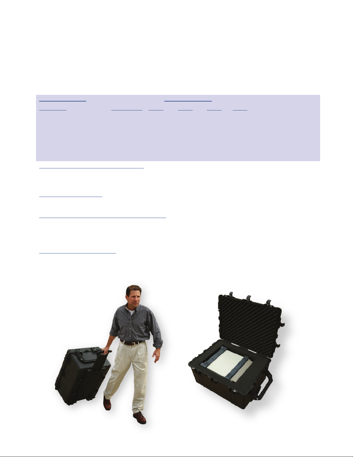
Hard Sided Transit Case with Wheels
Page 15
Description Part Number R2600 R2625 R2670 Notes
Encryption Options – Select any combination
AES CM807 NA Optional Optional Requires CM813
DES, DES-XL CM808 NA NA Optional Requires CM711
DVP-XL CM709 NA NA Optional Requires CM711
DVI-XL CM710 NA NA Optional Requires CM711
Accessories Supplied – May also be ordered separately
Oscilloscope Probe RTL4011A * * *
BNC to N Adapter 5884300A98 * * *
DC Power Connection Kit RPX4097A * * *
Telescoping Antenna TSBN * * *
90 Degree BNC for Antenna M55339/14-003 * * *
Microphone 50-P26922A001 * * *
Signal Generator Termination
(50 ohm) 28-P29965H104 * * *
Operators Manual (on CD) *6880386B72 *6880309J83 *6880309F17
Power Cord CCW353 * * *
Spare RF Fuses GG6530277C002 * * *
BNC RF ‘T’ 31-2208 * Required for cable fault testing
RF Detector Probe RLN4748A * Required for cable fault testing
Additional Accessories – Order Separately
Canvas Carrying Case 1580357B77 Protects unit when used in the field
Hard Sided Transit Case w/wheels 202620-01 Shipping Protection
Isolation Transformer Isolate output signal
for baseband output 0180302E83 from chassis ground
Isolation Transformer Isolate input signal
for baseband output 0180302E82 from chassis ground
RF Detector probe with 50 ohm
termination 5880345B96
Programmers Reference Manual 6880309E55 Includes RS232 and IEEE 488.2
Service Manual on CD RLN5237A
(Requires CM711, CM712, or CM713)
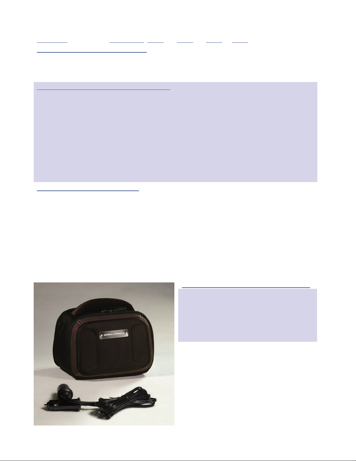
Portable Power Pack for R2600 Analyzer s
Portable Power Pack for R2600 Series Analyzers
STANDARD CAPACITY - PART # 2 01915-01
Number of Battery Packs One
Voltage 12 VDC
Battery Capacity 10 Amp/Hour
Weight 5.75 lb
Approximate Run Time > 1 Hour
Dimensions (inches) 6 x 8.5 x 6
HIGH CAPACITY - PART # 201915-02
Number of Battery Packs Two
Voltage 12 VDC
Battery Capacity 20 Amp/Hour
Weight 9.5 lb
Approximate Run Time > 2 Hours
Dimensions (inches) 6 x 8.5 x 6
NA – Option Not Available
*Accessory Included with model
15
Page 16
R2600 Series Communications System Analyzers
Service, maintenance
and technical support
For support on General Dynamics test equipment contact:
United States:
Motorola Test Equipment Service Center
2216 Galvin Drive
Elgin, IL 60123
Phone: 800-323-6967
Canada:
Navair, Inc.
6375 Dixie Road
Mississauga, Ontario
Canada, L5T2E7
Phone: 800-668-7440
Europe, the Middle East, and Africa:
Motorola Test Equipment Service Center
Heinrich-Hertz Strasse 1
65232 Taunusstein-Neuhof
Phone: +49-6128-700
Asia and the Pacific Rim (excluding Japan):
Motorola Electronics Pte Ltd
Motorola Innovation Centre, CGISS-7th Floor
12 Ang Mo Kio Street 64
Ang Mo Kio Industrial Park 3
Singapore 569088
Phone: +65-6486-3256
Fax: +65-6486-3257
Japan:
Nextec Japan Ltd.- Nextec High Tech Center
10-8 Mitsuzawanakamachi
Yokohama City, Kanagawa Protecture
Japan
Phone: +81-45-410-2287
Australia and New Zealand:
Australian Support Center
Motorola Australia Pty Ltd
10 Wesley Court
Tally Ho Business Park
East Burwood, VIC 3151
Australia
Phone: +61-3-9847-7725
Fax: +61-3-9847-7755
All trademarks indicated as such herein are trademarks of General
Dynamics ® Reg. U.S. Pat. & Tm. Off. All other product or service names
are the property of their respective owners. © 2007 General Dynamics.
All rights reserved. General Dynamics reserves the right to make changes
in its products and specifications at any time and without notice.
1915 Harrison Road, Longview, TX 75604
Telephone: (903) 295-1480 • Fax: (903) 295-1479 • Email: [email protected]
Please visit our web site at www.gdsatcom.com/cte.html to find the representative in your area.
Hudson 5474-550 • 11/07
 Loading...