

Page 1
GENERAL DYNAMICS
AIS
DOCUMENT NO.
A014
REV. C
*A014*
TEST EQUIPMENT FACILITY
ELECTRICAL STANDARDS LABORATORY
CALIBRATION PROCEDURE
FOR
SENCORE
LC53/75/101
Z METERS
Original 10/31/94
Revision C 03/31/98
Page 2

Calibration Procedure for Sencore LC53/75/101 Z Meters
ORIGINATED BY (please print): Brian Bonds
SIGNATURE DATE:
TESTED BY (please print): Dave Lepley
REVIEWED BY (please print): Greg Pearce
APPROVED BY (please print): Dan Tominson
SIGNATURE DATE:
SIGNATURE DATE:
SIGNATURE DATE:
INFORMATION NEEDED TO BEGIN
REFERENCES
Sencor LC53 Operation, Application, and Maintenance manual
Sencor LC75 Operation, Application, and Maintenance manual
Sencor LC101 Operation, Application, and Maintenance manual
ENVIRONMENTAL CONDITIONS
y Temperature: 22° to 24°C
y Relative Humidity: < 70%
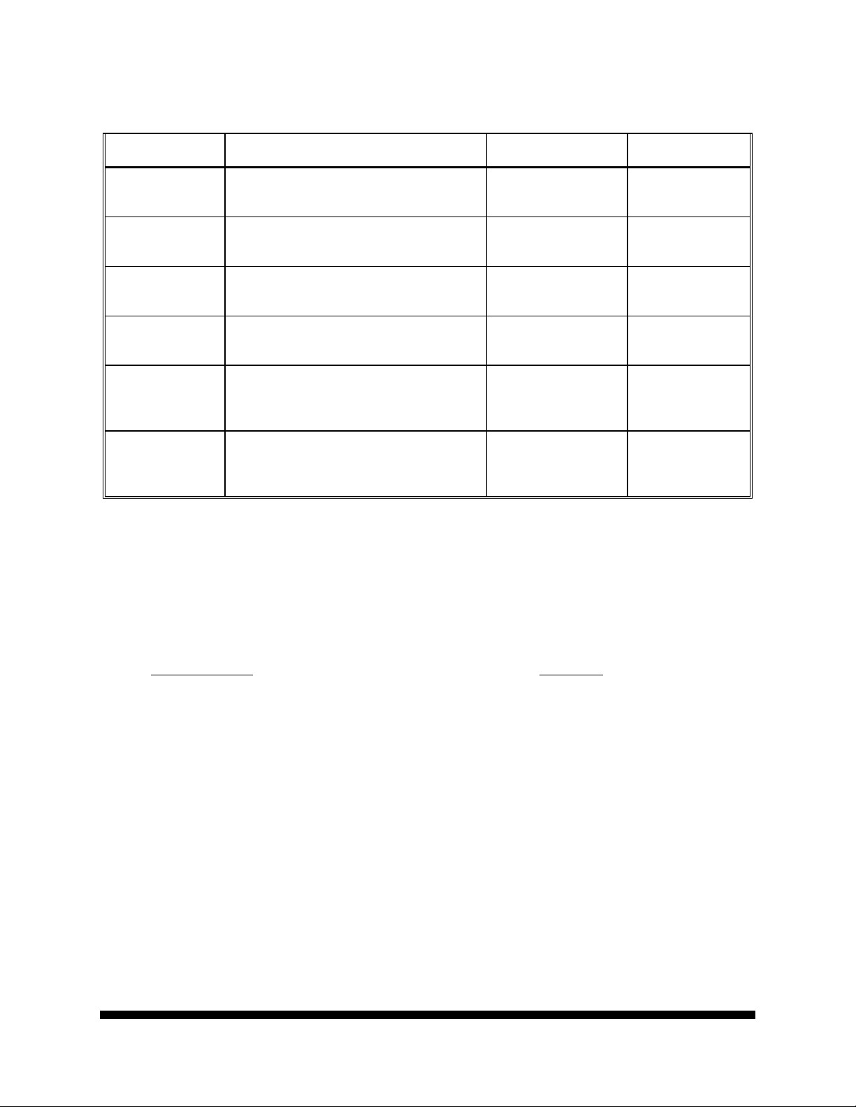
STANDARDS REQUIRED
Generic
Description
Decade Resistance
Box
Parameters & Ranges
Parameter: Resistance
Ranges: Decades from 1 to 100 Ω/Step
Acceptable Accuracy Recommended
(used for the LC75/101 cal only)
Decade Capacitor
Box
Parameter: Capacitance
Ranges: Decades from 100 pF/Step to
0.1 μF/Step
Decade Capacitor
Box
Parameter: Capacitance
Ranges: 1 μF/Step (to 9 μF)
Standard Inductor Parameter: Inductance
Ranges: 100 μH
± 1%
± 1%
± 1%
± 1%
Standard(s)
Gen Rad 1433-F
Gen Rad 1423-A
Gen Rad 1424-A
Gen Rad 1482-B
DOCUMENT NO. A014 SENCORE LC53/75/101 Z METERS
Revision C
*A014* Page 1 of 7
Page 3
STANDARDS REQUIRED (Cont)
Generic
Description
Standard Inductor Parameter: Inductance
Ranges: 1 mH
Standard Inductor Parameter: Inductance
Ranges: 10 mH
Standard Inductor Parameter: Inductance
Ranges: 100 mH
Standard Inductor Parameter: Inductance
Ranges: 1 H
Standard Inductor Parameter: Inductance
Ranges: 10 H
(used for the LC75/101 cal only)
Digital Multimeter Parameter: DC Volts
Ranges: 3 to 1000 V
(used for the LC75/101 cal only)
ACCURACY STATEMENT
All parameters tested by this procedure meet or exceed the required 4:1 test accuracy ratio.
ADDITIONAL EQUIPMENT REQUIRED
Equipment Type
Electrolytic Capacitor, 750 μF (LC75/101 cal only)................Sprague COE-9
Capacitor, 600VDC, 0.1 μF (LC75/101 cal only)...Sprague CP09A1KF104K3
WARM-UP TIMES
Allow at least 10 minutes for the equipment to warm up before starting the calibration.
ADDITIONAL INFORMATION
Paragraph/Section 1 (page 3) provides the calibration instructions for the Sencore LC75/101 Z
Meters. Paragraph/Section 2 (page 6) provides the calibration instructions for the Sencore LC53
Z Meter.
......................................................................... Model No.
Parameters & Ranges
Acceptable Accuracy Recommended
Standard(s)
± 1%
± 1%
± 1%
± 1%
± 1%
± 1%
Gen Rad 1482-E
Gen Rad 1482-H
Gen Rad 1482-L
Gen Rad 1482-P
Gen Rad 1482-T
Fluke 8520A
SENCORE LC53/75/101 Z METERS DOCUMENT NO. A014
Page 2 of 7
*A014* Revision C
Page 4

SUMMARY OF CHANGES
This is an administrative revision to meet General Dynamics Decision Systems format.
HOW TO CALIBRATE THE EQUIPMENT
1. Perform the Calibration of the LC75/101 Z Meter Unit Under Test (UUT).
a. To perform the Zeroing Adjustments, complete the following steps:
(1) Check the UUT display indication (no buttons pressed) for an indication of all zeros. If
the display does not read zero, adjust the single control on the right side of the UUT
rear panel for a display reading of 000.
(2) Short the test leads together and press the front panel INDUCTORS VALUE test
button.
(3) Adjust the front panel LEAD ZERO adjustment for a 00.0 reading on the front panel
display.
(4) With the test leads still shorted, press the front panel CAPACITORS ESR test button
and adjust the ESR ZERO control on the rear panel (upper left side) for a display
reading of 0.00.
(5) Open the test leads and place the test leads so they are close but not touching each
other.
(6) Press the front panel CAPACITORS VALUE test button and adjust the CAP ZERO
control on the rear panel (lower left) for a front panel display reading of 00.0. This
completes the zeroing adjustments for the UUT.
b. To perform the Calibration, complete the following steps:
(1) On the GR 1423-A Decade Capacitor, short the LOW terminal on the right side of the
unit to the chassis.
(2) On each of the two HIGH terminals of the GR 1423-A, place a small bare wire which
will be convenient for placing the UUT test leads. With the UUT zeroed [as noted in
step 1a(6) above], attach the UUT test leads to the wires on the GR 1423-A HIGH test
terminals.
(3) On the GR 1423-A, adjust the decades to C = 0.0001 μF (100 pF).
(4) On the UUT, press the CAPACITORS VALUE button. The UUT display must read
between 90.0 and 110.0 pF.
DOCUMENT NO. A014 SENCORE LC53/75/101 Z METERS
Revision C
*A014* Page 3 of 7
Page 5

(5) Set the GR 1423-A decades to values listed in Table 1 (below) and assure that the
UUT display reads within the ± 5% limits noted. After setting the GR 1423-A to the
value indicated, press the UUT CAPACITORS VALUE button to observe the readout.
Table 1
GR 1423-A Decade
Setting (μF)
UUT Readout
Lower Limit
UUT Readout
Upper Limit
0.0008 (800 pF) 760 pF 840 pF
0.007X (8 nF) 7600 pF 8400 pF
0.079X (80 nF) 76000 pF 84000 pF
0.799X (800 nF)
0.760 μF 0.840 μF
(6) Replace the GR 1423-A capacitor with a GR 1424-A and set it to 8 uF. Press the
UUT CAPACITORS VALUE button and observe that the UUT readout equals the
calibrated value of the GR 1424-A (as marked on the unit) ± 5%.
(7) An available 750 μF electrolytic capacitor should be used to check operation of the
highest UUT capacitance range. The test capacitor has an approximate value
between 840 and 860 μF. If the UUT readout value for the electrolytic capacitor
differs significantly from that of previous calibrations, the capacitor should be checked
using an HP 4274A (or equivalent) LCR Meter to determine if the actual capacitance
has changed. Significant variation from previously measured values could indicate
malfunction of the UUT.
(8) Replace the test capacitor with a GR 1433-F Decade Resistance Box. Set all GR
1433-F dials to zero.
(9) On the UUT, press the CAPACITORS ESR button and adjust the LEAD ZERO
control for a UUT display reading of 0.00.
(10) On the GR 1433-F, set the dials to 8.00 Ω. The UUT display shall read between 7
and 9 Ω.
(11) Using Table 2 (below), set the GR 1433-F to each setting and assure that the UUT
readings are within the limits specified.
Table 2
GR 1433-F Decade
Resistance Setting
(Ω)
UUT Readout
Lower Limit
(Ω)
UUT Readout
Upper Limit
(Ω)
80 76 84
100 95 105
800 760 840
(12) Replace the GR 1433-F Resistance Decade Box with a GR 1482-B, 100 μH,
Standard Inductor. On the UUT, press the INDUCTORS VALUE button. The UUT
shall read between 95 and 105 μH.
SENCORE LC53/75/101 Z METERS DOCUMENT NO. A014
Page 4 of 7
*A014* Revision C
Page 6

(13) For each Standard Inductor listed in Table 3 (below), attach to the UUT and press the
INDUCTORS VALUE button. Assure that the UUT readouts are within the ± 5%
limits specified in Table 3.
Table 3
Standard Inductor
used
UUT Readout
Lower Limit
UUT Readout
Upper Limit
GR 1482-E (1 mH) 0.95 mH 1.05 mH
GR 1482-H (10 mH) 9.5 mH 10.5 mH
GR 1482-L (100 mH) 95 mH 105 mH
GR 1482-P (1 H) 0950 mH 1050 mH
GR 1482-T (10 H) 9500 mH 10500 mH
(14) Detach any standards or components used in the previous steps from the UUT
and store.
WARNING:
Use extreme caution when handling the leads in the following
steps. High voltages are applied to the leads when the UUT
CAPACITORS LEAKAGE button is pressed. Voltages will be
applied to the UUT test leads which w ill exceed 600 V. The
UUT test lead voltages may be harmful or even lethal to the
operator.
(15) On the UUT test leads, attach a 0.1 μF, (600 VDC) capacitor (observe proper polarity
if the capacitor is polarized) and a DMM. Set the UUT LEAKAGE RANGE switch to
ALL OTHER CAPACITORS (100 μA Max). The test capacitor is necessary because
the applied UUT test voltages are pulsed. Under certain conditions, peak values will
exceed the voltages indicated.
CAUTION:
NEVER USE A STANDARD CAPACITOR TO PERFORM THIS TEST
AS IT MAY BE DESTROYED.
(16) Set the UUT LEAKAGE VOLTAGE switch to its lowest range (1.5 or 3 V) setting.
(17) On the DMM set the switches to VOLTS DC and AUTO.
(18) Being sure that the operators hands are clear of the UUT test leads, press the UUT
CAPACITORS LEAKAGE button and read the applied voltage on the DMM. The
voltage shall equal the UUT LEAKAGE VOLTAGE switch setting ± 20%. This is
not a critical instrument parameter. The liberal tolerance given for this parameter
assures intended UUT operation.
(19) Repeat step 1b(18) for each setting of the LEAKAGE VOLTAGE switch up to the 400
V setting only.
DOCUMENT NO. A014 SENCORE LC53/75/101 Z METERS
Revision C
*A014* Page 5 of 7
Page 7

2. Perform the Calibration of the LC53 Z Meter UUT.
a. To perform the Zeroing Adjustments, complete the following steps:
(1) On the UUT, adjust the (unmarked) control on the right rear panel for a display
reading of 000.
(2) Short the test leads together and while pressing the front panel INDUCTORS VALUE
test button, adjust the front panel LEAD ZERO adjustment for a 00.0 μH reading on
the front panel display.
(3) With the UUT test leads spaced at least 1 inch apart (open), press the CAPACITORS
VALUE button and adjust the left rear panel LEAD BALANCE control for a display
reading of 00.0 pF.
(4) Repeat steps 2a(2) and 2a(3) at least once to reduce the effect of any adjustment
interaction.
b. To Calibrate the Capacitance function, complete the following steps:
(1) On the GR 1423-A Decade Capacitor, use a jumper wire or strap to short the LOW
terminal on the right side of the unit to the chassis.
(2) On each of the two HIGH terminals of the GR 1423-A, place a small bare wire which
will accommodate attachment of the UUT test leads. With the UUT zeroed
[performed in step 2a(1) thru 2a(4) above], attach the UUT test leads to the wires on
the GR 1423-A HIGH test terminals.
(3) On the GR 1423-A, adjust the decades to C = 0.0001 μF (100 pF).
(4) On the UUT, press the CAPACITORS VALUE button. The UUT display must read
between 90.0 and 110.0 pF.
(5) Set the GR 1423-A decades to values listed in the Table 4 below and assure that the
UUT display reads within the ± 5% limits specified. After setting the GR 1423-A to the
value indicated, press the UUT CAPACITORS VALUE button to observe the readout.
Table 4
GR 1423-A Decade
Setting (μF)
UUT Readout
Lower Limit
UUT Readout
Upper Limit
0.0008 (800 pF) 760 pF 840 pF
0.007X (8 nF) 7600 pF 8400 pF
0.079X (80 nF) 76000 pF 84000 pF
0.799X (800 nF)
0.760 μF 0.840 μF
(6) Replace the GR 1423-A capacitor with a GR 1424-A and set it to 8 μF. Press the
UUT CAPACITORS VALUE button and observe the UUT readout. The UUT readout
must equal the calibrated value of the GR 1424-A (as marked on the unit) ± 5%.
SENCORE LC53/75/101 Z METERS DOCUMENT NO. A014
Page 6 of 7
*A014* Revision C
Page 8

c. To Calibrate the Inductance function, complete the following steps:
(1) Replace the GR 1424-A Capacitance Decade with a GR 1482-B, 100 μH, Standard
Inductor.
(2) On the UUT, press the INDUCTORS VALUE button. The UUT must read betw een
95 and 105 μH.
(3) Attach the UUT to each of the Standard Inductors listed in Table 5 below and press
the INDUCTORS VALUE button. Assure that the UUT readouts are within the
± 5% limits specified in Table 5.
Table 5
Standard Inductor
used
UUT Readout
Lower Limit
UUT Readout
Upper Limit
GR 1482-E (1 mH) 0.95 mH 1.05 mH
GR 1482-H (10 mH) 9.5 mH 10.5 mH
GR 1482-L (100 mH) 95 mH 105 mH
GR 1482-P (1 H) 0950 mH 1050 mH
(4) Return all standards used in the previous steps to their designated storage locations.
DOCUMENT NO. A014 SENCORE LC53/75/101 Z METERS
Revision C
*A014* Page 7 of 7
 Loading...