

Page 1
8:1 SCANNING
IR THERMOMETER
WITH
TRICOLOR LCD
USER’S MANUAL
IRTC40
Please read this manual carefully and thoroughly
before using this product.
Page 2

TABLE OF CONTENTS
Introduction . . . . . . . . . . . . . . . . . . .3 –6
Key Features . . . . . . . . . . . . . . . . . . 6 –7
What’s in the Package . . . . . . . . . . . . . . 7
Safety Instructions . . . . . . . . . . . . . . 7 –8
Product Overview . . . . . . . . . . . . . 8 – 11
Setup Instructions . . . . . . . . . . . . . . . . 11
Activate Batteries . . . . . . . . . . . . . . 11
Operating Instructions . . . . . . . . . 12 – 18
Conventional IRT Mode . . . . . 12 – 13
Scan Mode . . . . . . . . . . . . . . . 13 – 16
Operating Tips . . . . . . . . . . . . 17 – 18
Specifications . . . . . . . . . . . . . . . 19 – 20
Maintenance Tips . . . . . . . . . . . . . 20 – 21
Warranty Information . . . . . . . . . . 21 – 22
General’s Return for Repair Policy . . . . 23
Guide de L'Utilisateur . . . . . . . . . 24 – 47
Manual del Usuario . . . . . . . . . . . 48 – 72
2
Page 3

INTRODUCTION
Thank you for purchasing General Tools &
Instruments’ IRTC40—an 8:1 Scanning IR
Thermometer with Tricolor LCD. Please read
this manual carefully and thoroughly before
using the instrument.
The IRTC40 measures the surface
temperature of a surface or object from a
distance by using an infrared (IR) sensor to
quantify its thermal radiation. This noncontact measurement capability allows you
to safely determine the temperature of very
hot or cold surfaces, inaccessible or hardto-reach objects and toxic substances. A
laser pointer identifies the target area being
measured. Readings are displayed on a
backlit LCD.
The IRTC40’s scanning function, which is
enabled by a three-color LCD backlight, is
an especially convenient and time-saving
feature. In many applications—such as
finding thermal leaks in a house or
detecting a batch of undercooked food—
the absolute temperature of a surface is
less important than the temperature of the
3
Page 4

surface relative to surfaces around it.
Engineers call this difference 욼T, and
understanding 욼T is the key to using the
scanning function of the IRTC40.
Another way to think of 욼T is as one-half
the width of a temperature “window”
centered on a reference temperature. As an
example, for a reference temperature (Tref)
of 75°F, choosing a 욼T of 5°F would
establish a temperature window that spans
the 10° difference between 70° and 80°.
Any surface cooler than 70° would fall
below the cold edge of the temperature
window. Any surface hotter than 80° would
fall above the hot edge of the window.
What the IRTC40 does extremely well and
quickly is to place scanned targets into one
of three color-coded categories: green for
targets within the temperature window (Tref
plus and minus 욼T), red for targets hotter
than Tref plus 욼T, and blue for targets
cooler than Tref minus 욼T. The instrument
simultaneously uses sound to categorize
scanned targets by temperature. Targets
colder than the reference temperature ±욼T
generate a slow beeping sound and a
4
Page 5

display indication of LOW, targets hotter
than the reference temperature ±욼T
produce fast beeping and a display
indication of HIGH, and targets within the
“Goldilocks” zone—not too hot and not too
cold—yield silence and a display indication
of NORMAL.
The IRTC40 automatically enters
conventional (non-scanning) IRT mode
when you squeeze and hold the trigger for
three seconds. To enter scanning mode, you
set a reference temperature and a “setpoint
bandwidth” representing twice the value of
욼T. In practice, what most professionals
use as a reference is something they
consider at “normal” temperature—an
interior wall of a room, for example. Setting
the IRTC40’s reference temperature to this
value requires that you point the gun at the
reference object and press a button on the
front panel. Doing so causes that
temperature to appear at the right of the
term REF on the LCD.
In scanning mode, the setpoint bandwidth
can be set to any of three values—
1°F (0.5°C), 5°F (3°C) or 10°F (5.5°C).
5
Page 6

The bandwidth you choose should be
appropriate for the application. Typically, the
narrowest setpoint band (1°F/0.5°C) is used
to monitor the temperature of processes
requiring precise quality control (food
preparation, for example). The two wider
bands ±5°F (3°C) and ±10°F (5.5°C) are
used to detect deviations from normal that
are more tolerable (a small heat leak
through a crack in a wall that would be too
expensive to repair, for example).
KEY FEATURES
• In scanning mode, LCD backlight color
(red, green or blue) and beeper speed
(fast, silent or slow) indicate—with no
need to check readout—whether
temperature of target is above, within or
below reference temperature ± setpoint
bandwidth.
• Choice of three setpoint bandwidths:
1°, 5° and 10°F (0.5°, 3° and 5.5°C)
• Ideal for making relative temperature
measurements—such as in energy
auditing
6
Page 7

• Large backlit LCD automatically holds
reading when trigger is released
• Accuracy of 2% of reading or 3.6°F (2°C)
• To extend battery life, backlight shuts off
after 15 seconds of inactivity and
instrument powers off after 60 seconds
WHAT’S IN THE PACKAGE
The IRTC40 comes in a blister pack with a
wrist strap and two pre-installed “AAA”
batteries. A hard copy of this user’s manual
is inside the fold-over blister card.
SAFETY INSTRUCTIONS
CAUTION!
The IRTC40 is a Class 3R laser product that
emits less than 5mW of radiation. Avoid
looking directly at the laser pointer. U.S. law
prohibits pointing a laser beam at aircraft;
doing so is punishable by a fine of up to
$10,000 and imprisonment.
The laser may cause discomfort if viewed
directly. Your eyes’ nature aversion reflex
will prevent you from looking at the beam
7
Page 8

long enough to cause harm. However, keep
the IRTC40 out of the hands of children,
especially if you have pets.
Never stare at the laser beam through
binoculars or a magnifying glass.
Do not operate the IRT in the presence of
flammable or explosive gases or in
environments full of dust or static
electricity.
Do not operate near sources of strong
electromagnetic fields, such as arc welders
or induction heaters.
PRODUCT OVERVIEW
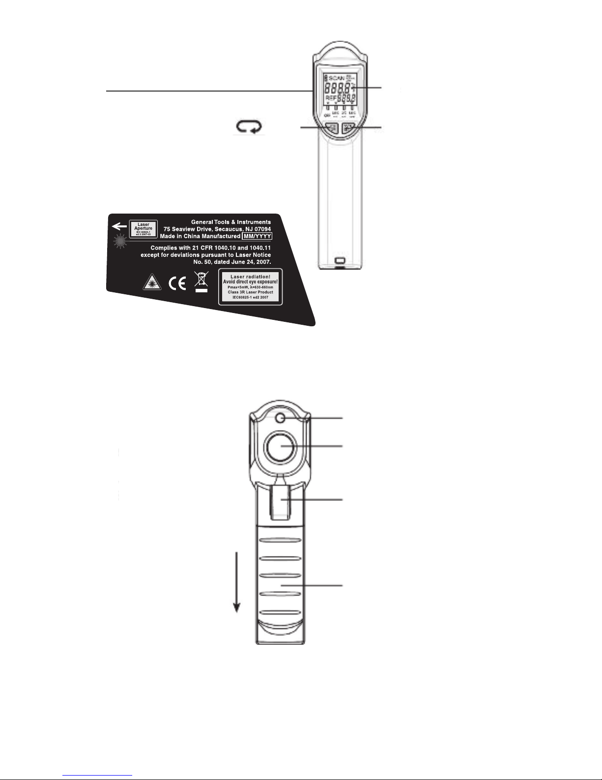
Fig. 1 shows all of the controls, indicators
and physical features of the IRTC40. Fig. 2
shows all of the icons and text that may
appear on the LCD. Familiarize yourself with
the locations and functions of the controls
and the meanings of the display icons
before moving on to the Setup and
Operating Instructions.
8
Page 9
9
/OFF
button
LCD
°C/°F/SET button
Laser pointer exit
IR sensor and lens
Measurement trigger
Battery compartment
Laser
identification/
certification/
warning/safety
labels (on left side
of gun)
(OPEN)
Fig. 1
Page 10
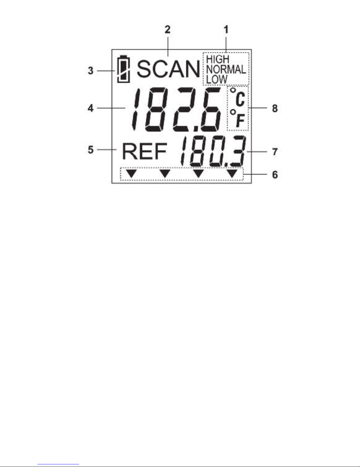
Fig. 2
1. Relationship of currently scanned
temperature to reference temperature
± setpoint bandwidth
2. Indicates measurement is taking place
3. Battery charge indicator
4. Temperature readout
5. Indicates reference temperature is at
right
6. pointers to selected setpoint
bandwidth, stenciled on housing directly
below LCD. Options are OFF, 1°F (0.5°C),
5°F (3°C) and 10°F (5.5°C)
10
Page 11

7. Current reference temperature
8. Temperature readout unit
SETUP INSTRUCTIONS
ACTIVATE BATTERIES
The IRTC40’s battery compartment (see
Fig. 1) is below the trigger and accessible
from the front of the grip.
Two “AAA” batteries are pre-installed in the
compartment. To activate them:
1. Open the battery compartment by
grasping its cover with your thumb and
forefinger and sliding the cover down and
away from the instrument.
2. Remove the plastic covering the batteries
and install them in series in the
compartment, observing the polarity
markings inside.
3. Close the battery compartment by sliding
the cover back up on its track until it
snaps shut.
11
Page 12

OPERATING
INSTRUCTIONS
CONVENTIONAL IRT MODE
1. Power on the IRTC40 by squeezing and
holding the yellow measurement trigger.
(If the LCD does not illuminate, the
battery is dead and must be replaced;
see p. 11 for instructions.) The LCD will
illuminate with a green backlight and the
term SCAN on the top line. The only
pointer visible on the bottom line of the
LCD will be the one above OFF. A red
laser pointer will be visible exiting the top
front of the gun.
2. Continue squeezing the trigger while
using the laser pointer to target surfaces
at different temperatures (windows, light
bulbs, your hand, etc.). Note that the
temperature readout will track changes
in temperature in the default
measurement unit of °F.
3. Release the trigger. Immediately, the
beeper will sound three times and the
term SCAN will disappear. Fifteen
12
Page 13

seconds later, the green LCD backlight
will turn off, but the last measurement
will remain visible. One minute later, the
IRTC40 will automatically power off.
4. To change the measurement unit to °C,
press the °C/°F/SET button after SCAN
disappears but before the instrument
powers off. To return to Fahrenheit
measurement, press the button again
during the same period of time.
SCAN MODE
1. Power on the IRTC40 by squeezing and
holding the yellow measurement trigger.
2. Without releasing the trigger, aim the gun
at an interior wall of the room you are in
and press the /OFF button once. This
will extinguish the pointer above OFF
and illuminate the pointer above
1°F/0.5°C.
3. Without releasing the trigger, press the
°C/°F/SET button. Doing so selects the
temperature of the wall as the reference
temperature and 1°F/0.5°C as the
setpoint bandwidth. On the LCD, the term
NORMAL will appear on the top line of
13
Page 14

the LCD, at the right of SCAN, and the
temperature of the wall will appear at the
right of REF.
4. Release the trigger. This will cause the
beeper to sound three times and the
terms SCAN and NORMAL to disappear
from the LCD. The reference temperature
will remain on-screen—but only for
1 minute.
5. Within 1 minute of releasing the trigger,
squeeze and hold the trigger again, but
this time while pointing the gun at your
hand. This will cause SCAN to reappear
on the top line. Note that as the laser
pointer hits your hand: 1) the color of
the LCD backlight changes from green
to red; 2) the term HIGH appears on the
top line; and 3) the beeper begins
to sound repeatedly and rapidly
(at 2 beeps/sec). Together, these visual
and audible alarms indicate that your
hand is at least 1°F (0.5°C) warmer than
the wall.
6. While continuing to target your hand,
release the trigger. Doing so will cause
the beeper to sound three times and the
14
Page 15

terms SCAN and HIGH to disappear from
the top line. Note that the temperature of
your hand will continue to be held and
displayed for up to 1 minute.
7. Repeat Steps 1 through 5, but instead of
targeting your hand, target a surface
colder than the wall (the inside of a
refrigerator, the outlet register of an
operating air conditioner in the summer,
or an exterior wall in the winter). Note
that as the laser pointer hits the colder
surface: 1) the color of the LCD backlight
changes from green to blue; 2) the term
LOW appears on the top line; and 3) the
beeper begins to sound repeatedly and
slowly (at 1 beep/sec). Together, these
visual and audible alarms indicate
that the targeted surface is at least
1°F (0.5°C) colder than the wall.
8. While continuing to target the cold
surface, release the trigger. This will
cause the beeper to sound three times
and the terms SCAN and LOW to
disappear from the top line. Note that
the temperature of the cold surface will
continue to be held and displayed for
up to 1 minute.
15
Page 16
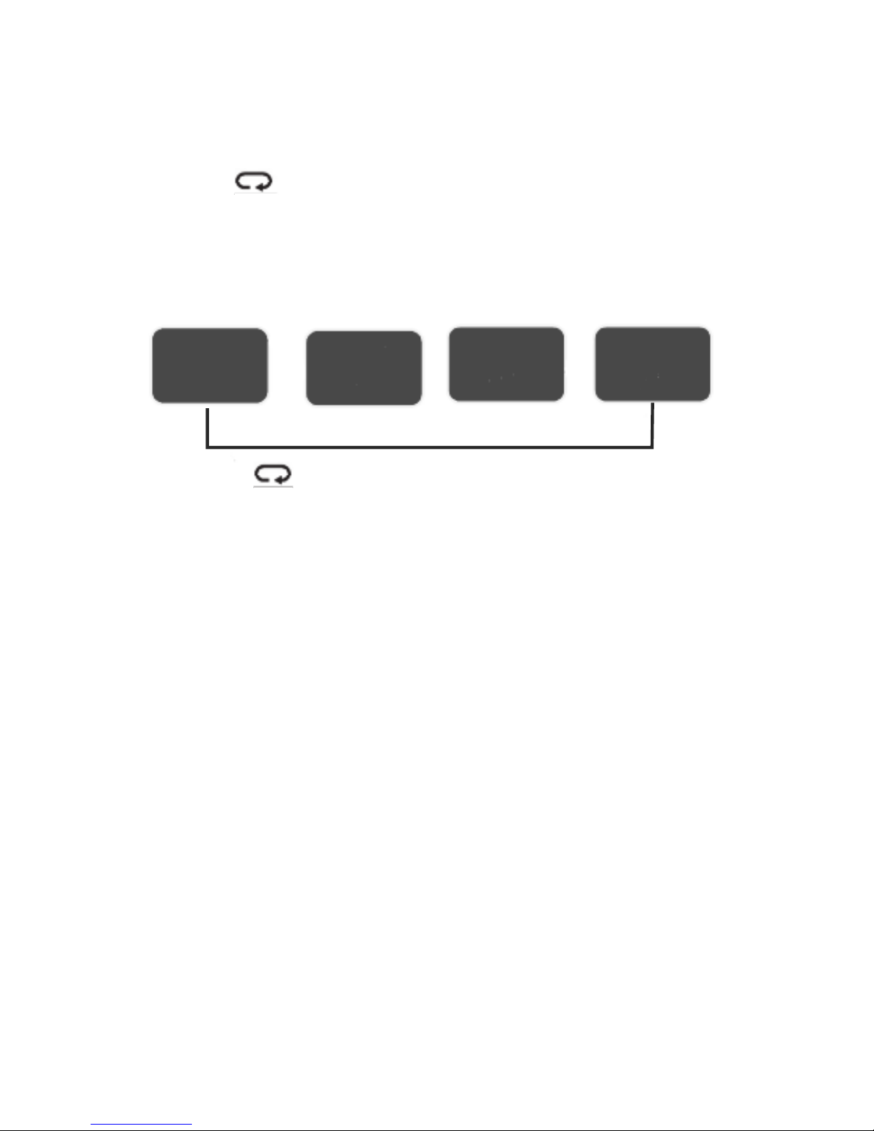
9. To widen the setpoint bandwidth from
1°F/0.5°C, with the trigger released and
a reference temperature on-screen press
the /OFF button once to illuminate the
pointer above 5°F/3°C, or twice to
choose 10°F/5.5°C.
10. To change the reference temperature,
you can: 1) allow the IRTC40 to power
itself off and establish a new reference
temperature “from scratch” by starting
with the pointer above OFF, or
2) overwrite the old reference
temperature by the new temperature
by targeting a different surface and
pressing the °C/°F/SET button.
16
Using the /OFF button to change the setpoint
bandwidth
1°F
0.5°C
5°F
3°C
10°F
5.5°C
OFF
Page 17

OPERATING TIPS
The first few times you use the IRTC40 in
Scan mode, don’t be too concerned about
which setpoint bandwidth to choose. With
experience you will learn whether a narrow
(1°F/0.5°C), normal (5°F/3°C) or wide
(10°F/5.5°C) value of 1/2 욼T is best for
your particular application. As part of your
education, note the effect of changing
setpoint bandwidths. For example, widen
the bandwidth from 1°F to 5°F and note
that some targets that caused the LCD
backlight to glow red before produce a
green backlight now.
Remember that the reference temperature
you acquire and the setpoint bandwidth you
choose disappear if you allow just one
minute to go by without pulling the trigger.
For this reason, you can expect to repower
the IRT often.
The diagram on the next page illustrates the
8:1 distance-to-spot (D:S) ratio (field of
view) of the IRTC40. To ensure that your
measurements accurately represent target
temperature, move the IRT close enough to
17
Page 18
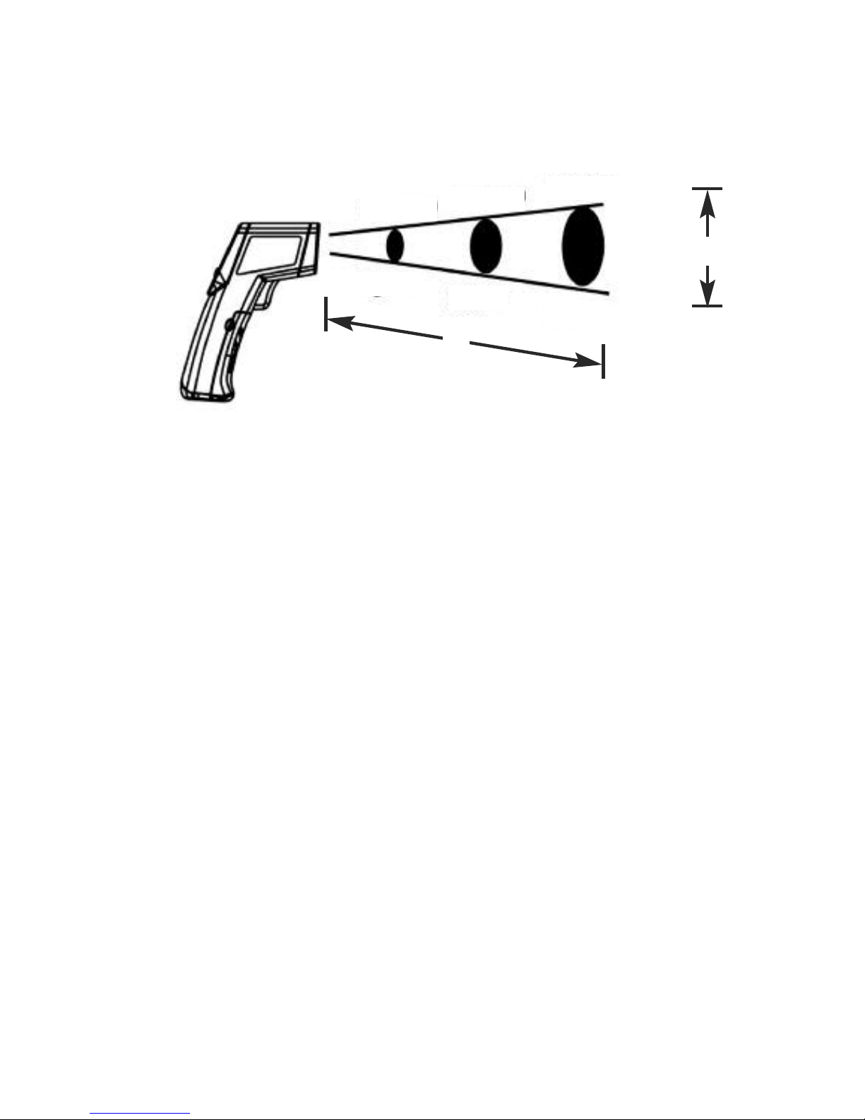
S
inches
mm
D
D:S=8:1
25@200
1@8
2@16
3@24
50@400
75@600
The IRTC40’s field of view
the target so the IR sensor only detects
radiation from the target and excludes
radiation from its surroundings.
The IRTC40 cannot make accurate
measurements if there is glass or plastic
between it and the target.
When the ambient temperature is higher
than 104°F (40°C) or lower than 32°F (0°C),
the LCD will show the following error
message: Err.
When the temperature of a target exceeds
the IRTC40’s specified maximum of 968°F
(520°C), the LCD will display a message
of Hi.
When the temperature of a target is less
than the IRTC40’s specified minimum of
-36.4°F (-38°C), the LCD will display a
message of Lo.
18
Page 19

SPECIFICATIONS
Distance-to-Spot Ratio: 8:1
Temperature Measurement Range:
-36.4° to 968°F (-38° to 520°C)
Temperature Measurement Accuracy:
±2% of reading or ±3.6°F (2°C),
whichever is greater
Display Resolution: 0.1° (F or C)
Emissivity: Fixed at 0.95
Response Time: 1 second for 95% response
Infrared Bandwidth: 7.5 to 13.5μm
Laser Power: Class 3R (<5mW)
Operating Temperature: 32° to 104°F
(0° to 40°C) @<75% RH
Storage temperature: -4° to 140°F
(-20° to 60°C)
High Temperature Beeper Frequency: 2 Hz
Low Temperature Beeper Frequency: 1 Hz
Backlight Auto Shutoff Trigger: 15 seconds
of inactivity
Instrument Auto Power Off Trigger: 1 minute
of inactivity
19
Page 20
Dimensions: 6.30 x 1.57 x 4.65 in.
(160 x 40 x 118mm)
Weight: 5.47 oz. (155g) (including batteries)
Power Source: (2) “AAA” batteries (included)
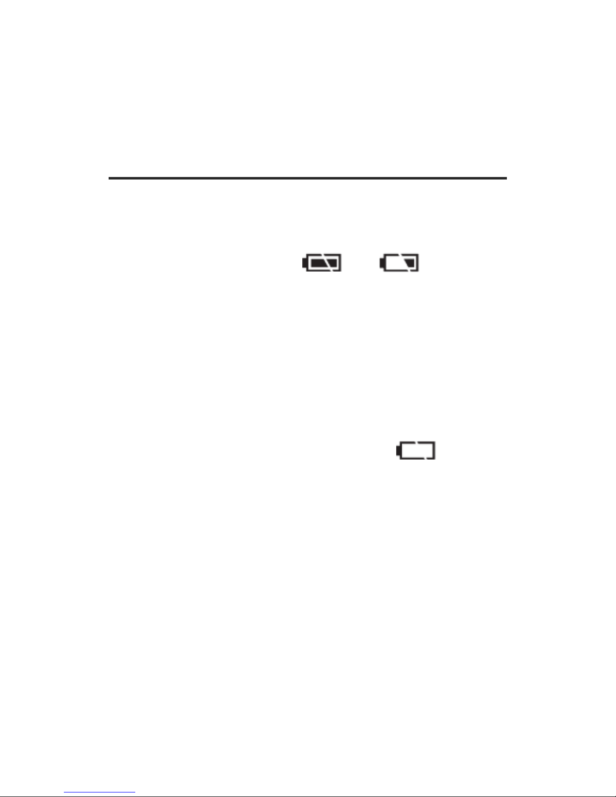
MAINTENANCE TIPS
When the battery charge indicator (see
Fig. 1) changes from to , allow
the IRTC40 to power itself off and replace
the weak batteries by fresh batteries as
soon as possible, following the instruc tions
on page 11 of this manual. Be aware that
measurements remain valid even though
the batteries have grown weak. When the
battery charge icon changes to ,
replace the batteries immediately.
Clean the infrared sensor lens (see Fig. 1)
often with compressed air or a moist cotton
cloth. Never use a solvent or an abrasive
cleaner. To clean the housing, use a soft,
damp cloth.
Abrupt temperature changes will cause
condensation and possible vapor
penetration. Clean the LCD after the vapor
evaporates. Blow off loose particles with
20
Page 21

compressed air. Gently brush remaining
debris away with a lens hair brush.
Remove the batteries if you don’t expect to
use the IRTC40 for an extended period of
time (months or years).
Do not drop or disassemble the unit or
immerse it in water.
WARRANTY
INFORMATION
General Tools & Instruments’ (General’s)
IRTC40 8:1 Scanning IR Thermometer with
Tricolor LCD is warranted to the original
purchaser to be free from defects in
material and workmanship for a period of
one year. Subject to certain restrictions,
General will repair or replace this
instrument if, after examination, the
company determines it to be defective in
material or workmanship. The warranty
period begins on the date of purchase. You
are encouraged to register your product
online. General will extend your warranty an
additional 60 days if you register at
www.generaltools.com/ProductRegistry.
21
Page 22

This warranty does not apply to damages
that General determines to be from an
attempted repair by non-authorized
personnel or misuse, alterations, normal
wear and tear, or accidental damage. The
defective unit must be returned to General
Tools & Instruments or to a Generalauthorized service center, freight prepaid
and insured.
Acceptance of the exclusive repair and
replacement remedies described herein is a
condition of the contract for purchase of
this product. In no event shall General be
liable for any incidental, special,
consequential or punitive damages, or for
any cost, attorneys’ fees, expenses, or
losses alleged to be a consequence of
damage due to failure of, or defect in any
product including, but not limited to, any
claims for loss of profits.
Register now at
www.generaltools.com/ProductRegistry to
receive a 60-day extension to your
warranty.
22
Page 23

23
RETURN FOR
REPAIR POLICY
Every effort has been made to provide you
with a reliable product of superior quality.
However, in the event your instrument
requires repair, please contact our
Customer Service to obtain an RGA (Return
Goods Authorization) number before
forwarding the unit via prepaid freight to the
attention of our Service Center at this
address:
General Tools & Instruments
75 Seaview Drive
Secaucus, NJ 07094
212-431-6100
Remember to include a copy of your proof
of purchase, your return address, and your
phone number and/or e-mail address.
Page 24

THERMOMÈTRE
INFRAROUGE
À BALAYAGE 8:1
AVEC ÉCRAN À
CL TRICOLORE
GUIDE DE L'UTILISATEUR
IRTC40
24
Lisez attentivement le présent guide
avant d'utiliser ce produit
Page 25

TABLE DES MATIÈRES
Introduction . . . . . . . . . . . . . . . . . 26 – 29
Caractéristiques . . . . . . . . . . . . . . . . . . 30
Contenu de l'emballage . . . . . . . . . . . . 31
Consignes de sécurité . . . . . . . . . 31 – 32
Vue d'ensemble du produit . . . . . 32 – 35
Instructions de mise en marche . . . . . 35
Activation des piles . . . . . . . . . . . . . 35
Instructions d'utilisation . . . . . . . 36 – 43
Mode de thermomètre
infrarouge conventionnel . . . . . 36 – 37
Mode de balayage . . . . . . . . . . 37 – 41
Conseils d'utilisation . . . . . . . . 41 – 43
Spécifications . . . . . . . . . . . . . . . 43 – 44
Conseils d'entretien . . . . . . . . . . . 44 – 45
Renseignements concernant
la garantie . . . . . . . . . . . . . . . . 46 – 47
Politique de retour pour réparation
de General . . . . . . . . . . . . . . . . . . . . 47
25
Page 26

INTRODUCTION
Merci d'avoir acheté le IRTC40 de General
Tools & Instruments, un Thermomètre
infrarouge à balayage 8:1 avec écran à CL
tricolore. Veuillez lire attentivement le
présent guide avant d'utiliser cet
instrument.
Le IRTC40 mesure à distance la
température superficielle d'une surface ou
d'un objet au moyen d'un capteur
infrarouge afin d'en quantifier le
rayonnement thermique. Cette capacité de
mesure sans contact vous permet de
déterminer, de façon sécuritaire, la
température de surfaces très chaudes ou
très froides, d'objets inaccessibles ou de
substances toxiques. Un pointeur laser
identifie la zone cible mesurée. La
température d'affiche sur un écran à CL à
rétroéclairage.
La fonction de balayage du IRTC40, qui est
rendue possible par un rétroéclairage
tricolore de l'écran à CL, est
particulièrement pratique et permet
notamment d'économiser du temps. Dans
26
Page 27

de nombreuses applications, par exemple
pour trouver les fuites thermiques d'une
maison ou identifier une certaine quantité
de nourriture qui n'est pas assez cuite, la
température absolue d'une surface a une
importance moindre que celle de la surface
relativement aux surfaces qui l'entourent.
Les ingénieurs nomment cette différence
욼T, et il est essentiel de comprendre 욼T afin
d'utiliser la fonction de balayage du IRTC40.
Une autre façon de concevoir 욼T est de
l'imaginer comme la moitié de la largeur
d'une «fenêtre» de température centrée sur
une température de référence. Par exemple,
pour une température de référence (Tref) de
25 °C, le choix d'un 욼T de 3 °C établirait
une fenêtre de température couvrant la
différence de 6° entre 22° et 28°. Toute
surface plus froide que 22° se situerait en
deçà de la limite froide de la fenêtre de
température. Toute surface plus chaude
que 28° serait située au-dessus de la limite
chaude de la fenêtre.
Ce que le IRTC40 fait très efficacement et
rapidement, c'est de placer les cibles
balayées dans une de trois catégories à
27
Page 28

code couleur : vert pour les cibles à
l'intérieur de la fenêtre de température (Tref
plus et moins 욼T), rouge pour les cibles
plus chaudes que Tref plus 욼T, et bleu pour
les cibles plus froides que Tref moins 욼T.
L'appareil utilise simultanément des sons
pour classer les cibles balayées selon leur
température. Les cibles plus froides que la
température de référence ±욼T provoquent
l'émission d'un signal sonore lent et
l'affichage du mot LOW, les cibles plus
chaudes que la température de référence
±욼T déclenchent un signal sonore rapide et
l'affichage du mot HIGH, et les cibles à
l'intérieur de la zone «Boucles d'Or» — ni
trop chaude, ni trop froide — ne produisent
aucun son et l'affichage indique NORMAL.
Le IRTC40 passe automatiquement au
mode de thermomètre infrarouge
conventionnel (sans balayage) lorsque vous
pressez et tenez la gâchette enfoncée
pendant trois secondes. Pour passer au
mode de balayage, il vous faut fixer une
température de référence et une «largeur
de bande de la valeur seuil» représentant
deux fois la valeur de 욼T. En pratique, la
28
Page 29

plupart des professionnels utilisent en guise
de référence ce qu'ils considèrent comme
une température «normale», par exemple le
mur intérieur d'une pièce. Pour régler la
température de référence du IRTC40 à cette
valeur, il faut pointer l'appareil vers l'objet
de référence et appuyer sur une touche du
panneau avant. Cette température
s'affichera sur l'écran, à droite du mot REF.
En mode de balayage, la largeur de bande
de la valeur seuil peut être réglée à
n'importe laquelle de ces trois valeurs :
0,5 °C, 3 °C ou 5,5 °C.
La largeur de bande que vous choisissez
devrait être appropriée à l'application. La
bande de valeur seuil la plus étroite (0,5 °C)
sert habituellement à surveiller la
température de processus qui requièrent un
contrôle de la qualité très précis (par
exemple la préparation de nourriture). Les
deux bandes plus larges, ±3 °C et ±5,5 °C,
sont utilisées pour détecter les écarts plus
tolérables par rapport à la normale (par
exemple une légère fuite de chaleur par une
fissure dans un mur qui serait trop coûteuse
à réparer).
29
Page 30

CARACTÉRISTIQUES
PRINCIPALES
• En mode de balayage, la couleur de
rétroéclairage de l'écran (rouge, vert ou
bleu) et le signal sonore (rapide, silencieux
ou lent) indiquent — sans devoir lire
l'écran — si la température de la cible se
situe au-dessus, à l'intérieur ou en deçà
de la largeur de bande de la valeur seuil
± de la température de référence.
• Choix de trois largeurs de bande de la
valeur seuil : 0,5, 3 et 5,5 °C
• Idéal pour les mesures de températures
relatives, par exemple dans le cadre
d'une vérification de l'efficacité
énergétique
• Le grand écran à CL à rétroéclairage
continue automatiquement d'afficher la
mesure lorsque la gâchette est relâchée
• Précision de mesure de 2% ou 2 °C
• Afin de prolonger la durée de vie de la
pile, le rétroéclairage s'éteint après
15 secondes d'inactivité et l'appareil
s'éteint après 60 secondes
30
Page 31

CONTENU DE
L'EMBALLAGE
Le IRTC40 est vendu dans un emballage
coque qui contient également une dragone
et deux piles pré-installé «AAA». Une copie
papier du présent guide de l'utilisateur se
trouve à l'intérieur du rabat de l'emballage.
CONSIGNES DE
SÉCURITÉ
ATTENTION!
Le IRTC40 est un produit laser de classe
3R qui émet un taux de radiation inférieur
à 5 mW. Évitez de fixer directement le
pointeur laser. La loi américaine interdit de
pointer un faisceau laser vers un aéronef;
un tel geste est passible d'une amende
allant jusqu'à 10 000$ et d'une peine
d'emprisonnement.
Le laser peut produire un inconfort si vous
le fixez directement. Le réflexe d'aversion
naturel de vos yeux vous empêchera de
regarder le faisceau assez longtemps pour
causer des dommages. Par précaution,
31
Page 32

tenez le IRTC40 hors de la portée des
enfants, particulièrement si vous avez des
animaux domestiques.
Ne fixez jamais le faisceau laser à travers
des jumelles ou une loupe.
N'utilisez pas le thermomètre infrarouge en
présence de gaz inflammable ou explosif,
ni dans un environnement saturé de
poussière ou d'électricité statique.
N'utilisez pas cet appareil près d'une
source de champ magnétique puissant, tel
qu'une soudeuse à arc électrique ou un
appareil chauffant à induction.
VUE D'ENSEMBLE
DU PRODUIT
La Figure 1 montre les commandes,
indicateurs et composantes du IRTC40.
La Figure 2 montre les icônes et le texte
pouvant s'afficher sur l'écran à CL.
Familiarisez-vous avec les positions et
fonctions de toutes les touches et la
signification des icônes affichées avant de
passer aux instructions de mise en marche
et d'utilisation.
32
Page 33

33
Touche
/OFF
Écran à CL
Touche °C/°F/SET
Sortie du pointeur laser
Capteur infrarouge
et lentille
Gâchette de mesure
Compartiment
des piles
Étiquettes
d'identification/
certification/
avertissement/
sécurité du laser (du côté
gauche de l'appareil)
(OPEN) (ouvrir)
Fig. 1
I
E
C
6
0
8
2
5
-
1
e
d
2
2
0
0
7
-
0
3
G
e
n
e
ra
l
T
oo
l
s
&
I
ns
t
rume
nt
s
7
5
S
e
a
v
i
e
w
D
ri
v
e
,
S
e
c
a
u
c
us
,
N
J
0
7
0
9
4
Fa
br
i
qué
e
n
Chi
ne
;
da
te
de
fa
br
i
c
a
ti
onÊ
:
1
1/
20
14
C
onf
orm
e
au
x
norm
es
21
C
FR
1040.
10
et
1040.
11
sau
f
l
es
except
i
ons
ci
t
ées
dans
l
e
docum
ent
«
Laser
N
o
t
i
ce
N
o
.
50
»,
p
u
b
l
i
é
l
e
24
j
ui
n
2007.
R
ayon
nement
laser
!
Év
i
t
e
z
t
out
e
e
x
pos
i
t
i
on
de
s
y
e
ux
!
P
u
i
s
s
a
n
c
e
m
á
x
.
<5
m
W
,
λ
=6
3
0
-
6
6
0
n
m
Pr
o
dui
t
l
a
s
e
r
d
e
c
l
a
s
s
e
3
R
I
E
C
6
0
8
2
5
-
1
e
d2
2
0
0
7
O
ri
f
i
ce
du
l
aser
Page 34

Fig. 2
1. Rapport entre la température balayée
actuelle et la largeur de bande de la
valeur seuil ± de la température de
référence
2. Indique qu'une mesure est en cours
3. Indicateur de charge des piles
4. Affichage de la température
5. Indique que la température de référence
se trouve à droite
6. Pointeurs vers la largeur de bande de
la valeur seuil sélectionnée, imprimée sur
le boîtier immédiatement sous l'écran à
CL. Les options sont OFF, 1°F (0.5°C),
5°F (3°C) et 10°F (5.5°C)
34
Page 35

7. Température de référence actuelle
8. Unité d'affichage de la température
INSTRUCTIONS DE MISE
EN MARCHE
ACTIVATION DES PILES
Le compartiment des piles du IRTC40
(voir Fig. 1) se situe sous la gâchette et est
accessible à l'avant de la prise de
l'appareil.
Deux piles «AAA» sont pré-installés dans le
compartiment. Pour les activer :
1. Ouvrez le compartiment des piles en
saisissant le couvercle avec le pouce et
l'index et en le faisant glisser vers le bas,
en l'éloignant de l'appareil.
2. Retirez le plastique qui recouvre les piles
et de les insérez en série dans le
compartiment, en respectant la polarité
indiquée à l'intérieur.
3. Refermez le compartiment des piles en
glissant le couvercle vers le haut sur ses
rails jusqu'à ce qu'il se ferme en
s'enclenchant.
35
Page 36

INSTRUCTIONS
D'UTILISATION
MODE DE THERMOMÈTRE
INFRAROUGE CONVENTIONNEL
1. Mettez le IRTC40 en marche en pressant
et en tenant la gâchette de mesure jaune
enfoncée. (Si l'écran à CL ne s'allume
pas, la pile est déchargée et doit être
remplacée; voir instructions p. 35.)
L'écran à CL s'allumera avec un
rétroéclairage vert et le mot SCAN
s'affichera sur la ligne supérieure. Le
seul pointeur visible sur la ligne
inférieure de l'écran sera celle située
au-dessus du mot OFF. Un pointeur laser
rouge sortant de la partie supérieure
avant de l'appareil sera visible.
2. Continuez à presser la gâchette tout en
visant des surfaces de différentes
températures (fenêtres, ampoules
électriques, votre main, etc.) à l'aide du
pointeur laser. Vous remarquerez que la
température affichée suivra les
changements de température en °F,
l'unité de mesure par défaut.
36
Page 37

3. Relâchez la gâchette. Un signal sonore
retentira immédiatement trois fois et le
mot SCAN disparaîtra. Quinze secondes
plus tard, le rétroéclairage vert de l'écran
à CL s'éteindra, mais la dernière
température mesurée demeurera visible.
Après une minute, le IRTC40 s' éteindra
automatiquement.
4. Pour changer l'unité de mesure à °C,
appuyez sur la touche °C/°F/SET après
que SCAN soit disparu mais avant que
l'appareil s'éteigne. Pour revenir à la
mesure en degrés Fahrenheit, appuyez
de nouveau sur la touche pendant la
même période.
MODE DE BALAYAGE
1. Mettez le IRTC40 en marche en pressant
et en tenant la gâchette de mesure jaune
enfoncée.
2. Sans relâcher la gâchette, pointez
l'appareil vers un des murs intérieurs de
la pièce où vous vous trouvez et appuyez
une fois sur la touche /OFF. Le
pointeur situé au-dessus du mot OFF
s'éteindra, et celui au-dessus de
1°F/0.5°C s'allumera.
37
Page 38

3. Sans relâcher la gâchette, appuyez sur la
touche °C/°F/SET. Ceci sélectionnera la
température du mur en tant que
température de référence et 1°F/0.5°C
en tant que largeur de bande de la valeur
seuil. À l'écran, le mot NORMAL
s'affichera sur la ligne supérieure à droite
de SCAN, et la température du mur
s'affichera à droite de REF.
4. Relâchez la gâchette. Un signal sonore
retentira trois fois et les mots SCAN et
NORMAL disparaîtront de l'écran à CL.
La température de référence demeurera
à l'écran, mais seulement pendant
1 minute.
5. Moins de 1 minute après avoir relâché la
gâchette, pressez et tenez-la enfoncée
de nouveau, mais cette fois en pointant
l'appareil vers votre main. Le mot SCAN
s'affichera sur la ligne supérieure de
l'écran. Remarquez que lorsque le
pointeur laser touche votre main : 1) la
couleur du rétroéclairage de l'écran à CL
passe du vert au rouge; 2) le mot HIGH
s'affiche sur la ligne supérieure; et 3) un
signal sonore commence à retentir de
façon répétée et rapide (à 2 bips/sec).
38
Page 39

Tous ensemble, ces signaux visuel et
sonore indiquent que votre main est plus
chaude que le mur d'au moins 0,5 °C.
6. Tout en gardant l'appareil pointé vers
votre main, relâchez la gâchette. Un
signal sonore retentira trois fois et les
mots SCAN et HIGH disparaîtront de
l'écran. Remarquez que la température
de votre main demeurera en mémoire
et restera affichée pendant jusqu'à
1 minute.
7. Répétez les étapes 1 à 5, mais plutôt que
de viser votre main, visez une surface
plus froide que le mur (l'intérieur d'un
réfrigérateur, la grille de sortie d'un
climatiseur en marche pendant l'été, ou
un mur extérieur en hiver). Remarquez
que lorsque le pointeur laser touche la
surface plus froide : 1) la couleur du
rétroéclairage de l'écran à CL passe du
vert au bleu; 2) le mot LOW s'affiche sur
la ligne supérieure; et 3) un signal sonore
commence à retentir de façon répétée et
lente (à 1 bip/sec). Tous ensemble, ces
signaux visuel et sonore indiquent que la
surface visée est plus froide que le mur
d'au moins 0,5 °C.
39
Page 40

8. Tout en gardant l'appareil pointé vers la
surface froide, relâchez la gâchette. Un
signal sonore retentira trois fois et les
mots SCAN et LOW disparaîtront de
l'écran. Remarquez que la température
de la surface froide demeurera en
mémoire et restera affichée pendant
jusqu'à 1 minute.
9. Pour augmenter la largeur de bande
de la valeur seuil par rapport à 0,5 °C,
alors que la gâchette est relâchée et
qu'une température de référence est
affichée à l'écran, appuyez sur la touche
/OFF une fois pour allumer le pointeur
au-dessus de 5°F/3°C ou deux fois
pour sélectionner 10°F/5.5°C.
10. Pour changer la température de
référence, vous pouvez : 1) laisser le
IRTC40 s'éteindre, puis établir une
nouvelle température de référence à
40
Utilisation de la touche /OFF pour changer la
largeur de bande de la valeur seuil
1°F
0.5°C
5°F
3°C
10°F
5.5°C
OFF
Page 41

partir de zéro, en commençant avec le
pointeur au-dessus de OFF, ou 2) en
remplaçant l'ancienne température de
référence par une nouvelle température
en visant une autre surface et en
appuyant sur la touche °C/°F/SET.
CONSEILS D'UTILISATION
Les quelques premières fois que vous
utilisez le IRTC40 en mode de balayage, ne
vous préoccupez pas de la largeur de bande
de la valeur seuil à choisir. L'expérience
vous apprendra si une valeur de 1/2 욼T
étroite (0,5 °C), normale (3 °C) ou large
(5,5 °C) est la meilleure pour une
application particulière. Dans le cadre de
votre apprentissage, observez l'effet que
produit le changement de la largeur de
bande de la valeur seuil. Par exemple,
accroissez la largeur de bande de 0,5 °C à
3 °C et remarquez que certaines cibles pour
lesquelles le rétroéclairage de l'écran à CL
s'illuminait auparavant en rouge produisent
maintenant un rétroéclairage vert.
N'oubliez pas que la température de
référence que vous fixez et la largeur de
bande de la valeur seuil que vous
41
Page 42

choisissez disparaissent si vous laissez
passer une seule minute sans presser la
gâchette. Attendez-vous donc à devoir
fréquemment remettre le thermomètre
infrarouge en marche.
Le diagramme au-dessous illustre le
rapport distance-surface (D:S) (champ de
vision) de 8:1 du IRTC40. Pour vous assurer
que vos mesures reflètent avec exactitude
la température de la cible, placez le
thermomètre infrarouge assez près de la
cible pour que le capteur infrarouge détecte
uniquement le rayonnement de la cible et
exclue celui des alentours.
Le IRTC40 ne peut pas effectuer une
mesure précise si du verre ou du plastique
le sépare de la cible.
42
S
pouces
mm
D
D:S=8:1
25@200
1@8
2@16
3@24
50@400
75@600
Champ de vision du IRTC40
Page 43

Lorsque la température ambiante est
supérieure à 40 °C ou inférieure à 0 °C,
l'écran à CL affiche le message d'erreur Err.
Lorsque la température de la cible est
supérieure au maximum spécifié du
IRTC40, c'est-à-dire 520 °C, l'écran à CL
affiche le message Hi.
Lorsque la température de la cible est
inférieure au minimum spécifié du IRTC40,
c'est-à-dire -38 °C, l'écran à CL affiche le
message Lo.
SPÉCIFICATIONS
Rapport distance-surface : 8:1
Étendue de mesure de la température :
-38 à 520 °C
Précision de mesure de la température :
±2% de lecture ou ±2 °C, selon le plus
élevé
Résolution d'affichage : 0,1 °C
Émissivité : Fixe à 0,95
Temps de réponse : 1 seconde pour 95% de
réponse
Largeur de bande infrarouge : 7,5 à 13,5 μm
Puissance du laser : Classe 3R (< 5 mW)
43
Page 44

Température d'utilisation : 0 à 40 °C @
< 75% HR
Température d'entreposage : -20 à 60 °C
Fréquence du signal sonore de température
élevée : 2 Hz
Fréquence du signal sonore de température
basse : 1 Hz
Déclenchement de l'arrêt automatique du
rétroéclairage : 15 secondes d'inactivité
Déclenchement de l'arrêt automatique de
l'appareil : 1 minute d'inactivité
Dimensions : 160 x 40 x 118 mm
Poids : 155 g (avec piles)
Source d'alimentation : 2 piles «AAA» (inclus)
CONSEILS D'ENTRETIEN
Lorsque l'indicateur de charge des piles
(voir Fig. 1) passe de à , laissez le
IRTC40 s'éteindre et remplacez dès que
possible les piles faibles par de nouvelles
piles en vous conformant aux instructions
en page 35 du présent manuel. Sachez que
les mesures demeurent valides même si les
piles sont faibles. Lorsque l'icône de charge
44
Page 45

des piles passe à , remplacez
immédiatement les piles.
Nettoyez fréquemment la lentille du capteur
infrarouge (voir Fig. 1) à l'aide d'air
comprimé ou d'un linge de coton humide.
N'employez jamais de solvant ni de
nettoyant abrasif. Pour nettoyer le boîtier,
utilisez un linge doux humide.
Les changements brusques de température
entraîneront la formation de condensation
et possiblement la pénétration de vapeur.
Nettoyez l'écran à CL une fois la vapeur
évaporée. Enlevez les particules non
adhérentes à l'aide d'air comprimé. Retirez
doucement les débris résiduels au moyen
d'une brosse à lentille.
Retirez les piles si vous prévoyez ne pas
utiliser le IRTC40 pendant une période
prolongée (plusieurs mois ou années).
Ne faites pas tomber l'appareil, ne le
désassemblez pas et ne l'immergez pas
dans l'eau.
45
Page 46

RENSEIGNEMENTS
CONCERNANT LA
GARANTIE
Le Thermomètre infrarouge à balayage 8:1 avec
écran à CL tricolore IRTC40 de General Tools &
Instruments (General) est garanti à l'acheteur
original contre tout défaut de matériaux et de
main-d'œuvre pour une période de un (1) an. À
l'intérieur de certaines limites, General réparera ou
remplacera cet instrument s'il établit, après
examen, la présence d'un défaut de matériaux ou
de main-d'œuvre. La période de garantie débute à
la date d'achat. Nous vous conseillons
d'enregistrer votre produit en ligne. General
prolongera votre garantie de 60 jours
supplémentaires si vous enregistrez ce produit au
www.generaltools.com/ProductRegistry.
La présente garantie ne s'applique pas aux
dommages que General juge découlant d'une
tentative de réparation par un personnel non
autorisé ou d'un usage abusif, de modifications,
d'une usure normale ou de dommages accidentels.
L'appareil défectueux doit être retourné à General
Tools & Instruments ou à un centre de service
autorisé de General, port payé et assuré.
L'acceptation des solutions de réparation et de
remplacement exclusives décrites ici est une
condition du contrat d'achat de ce produit. General
46
Page 47

ne pourra en aucun cas être tenu responsable de
dommages accessoires, particuliers, indirects ou
punitifs, ni de frais, honoraires d'avocat, dépenses
ou pertes présumés découler de tout dommage
provoqué par une défaillance ou un défaut du
produit, incluant notamment toute réclamation
pour perte de profits.
Enregistrez ce produit maintenant au
www.generaltools.com/ProductRegistry pour
recevoir une prolongation de 60 jours de votre
garantie.
POLITIQUE DE RETOUR
POUR RÉPARATION
Nous a
vons tout fait en notre pouvoir pour vous
offrir un produit fiable et de qualité supérieure.
Cependant, s'il advenait que votre instrument doive
être réparé, veuillez contacter notre Service à la
clientèle afin d'obtenir un numéro RMA (retour de
marchandise) avant de nous expédier l'appareil,
port payé, à l'attention de notre Centre de service
à l'adresse suivante :
General Tools & Instruments
75 Seaview Drive Secaucus, NJ 07094 U.S.A.
212-431-6100
N'oubliez pas d'inclure une copie de votre preuve
d'achat, votre adresse de retour, votre numéro de
téléphone et/ou votre adresse de courriel.
47
Page 48

General Tools & Instruments
GeneralToolsNYC
GENERAL TOOLS & INSTRUMENTS
75 Seaview Drive Secaucus, NJ 07094
PHONE (212) 431-6100 FAX (212) 431-6499
TOLL FREE (800) 697-8665
e-mail: sales@generaltools.com
www.generaltools.com
IRTC40 User’s Manual
Specifications subject to change without notice
NOTICE - NOT RESPONSIBLE FOR TYPOGRAPHICAL ERRORS.
©2015 GENERAL TOOLS & INSTRUMENTS
MAN# IRTC40
5/27/15
GENERAL TOOLS & INSTRUMENTS
75 Seaview Drive Secaucus, NJ 07094
U.S.A.
TÉL. (212) 431-6100 TÉLÉC. (212) 431-6499
SANS FRAIS (800) 697-8665
courriel : sales@generaltools.com
www.generaltools.com
Guide de l'utilisateur IRTC40
Spécifications sujettes à changement sans préavis
AVIS - NOUS NE SOMMES PAS RESPONSABLES DES ERREURS
TYPOGRAPHIQUES
©2015 GENERAL TOOLS & INSTRUMENTS
MAN NOIRTC40
09
/07/15
Page 49

TERMÓMETRO IR
DE BARRIDO 8:1
CON PANTALLA
TRICOLOR
MANUAL DEL USUARIO
IRTC40
49
Lea cuidadosamente todo este manual antes
de usar este producto.
Page 50

ÍNDICE
Introducción . . . . . . . . . . . . . . . . . 51 – 54
Características principales . . . . . . . . . 55
Contenido del paquete . . . . . . . . . . . . . 56
Instrucciones de seguridad . . . . . 56 – 57
Descripción general
del producto . . . . . . . . . . . . . . . . . 57 – 59
Instrucciones de preparación . . . . . . . 60
Activación de las baterías . . . . . . . 60
Instrucciones de operación . . . . . 61 – 67
Modo IRT convencional . . . . . 61 – 62
Modo de barrido . . . . . . . . . . 62 – 65
Consejos de operación . . . . . 65 – 67
Especificaciones . . . . . . . . . . . . . . . . . 68
Consejos de mantenimiento . . . . 69 – 70
Información de garantía . . . . . . . 70 – 71
Política de devolución para
reparaciones . . . . . . . . . . . . . . . . 71 – 72
50
Page 51

INTRODUCCIÓN
Gracias por comprar el IRTC40 de General
Tools & Instruments, un termómetro IR 8:1
con pantalla tricolor. Lea cuidadosamente
todo este manual antes de usar el
instrumento.
El IRTC40 mide la temperatura superficial
de una superficie o de un objeto a la
distancia, usando un sensor infrarrojo (IR)
para cuantificar su radiación térmica. Esta
capacidad de medición sin contacto le
permite determinar la temperatura de
superficies muy calientes o muy frías de
forma segura, de objetos inaccesibles o de
difícil acceso y de sustancias tóxicas. Un
puntero láser identifica el área en la cual se
mide la temperatura. Las lecturas se
muestran en una pantalla LCD iluminada.
La función de barrido del IRTC40, la cual se
habilita mediante la iluminación tricolor de
la pantalla, es una función especialmente
conveniente y rápida. En muchas
aplicaciones, como buscando fugas térmicas
en una casa o detectando una tanda de
comida poco cocida, la temperatura absoluta
51
Page 52

de una superficie no es tan importante como
la temperatura de esa superficie con
respecto a sus alrededores. Los ingenieros
llaman 욼T a esta diferencia, y el comprender
욼T es la clave para usar la función de
barrido del IRTC40.
Otra forma de pensar en el 욼T como la mitad
del ancho de una “ventana” de temperatura,
centrada en una temperatura de referencia.
Por ejemplo, para una temperatura de
referencia (Tref) de 25° C, un 욼T de 3 °C
establecería una ventana de temperatura
de 6 °C de ancho, yendo desde 22 °C hasta
28 °C. Toda fuente menor de 22 °C estará
por debajo del extremo frío de la ventana de
temperatura. Toda fuente mayor de 28 °C
estará por encima del extremo caliente de la
ventana de temperatura.
Lo que el IRTC40 realiza extremadamente
bien y rápido es colocar los blancos
escaneados dentro de una de las tres
categorías codificadas en colores: verde
para los blancos dentro de la ventana de
temperatura (Tref más y menos 욼T), rojo
para los blancos más calientes que Tref
más 욼T y azul para los blancos más fríos
52
Page 53

que Tref menos 욼T. El instrumento usa
sonido simultáneamente para categorizar
por temperatura los blancos escaneados.
Los blancos más fríos que la temperatura
de referencia ±욼T generan un pitido lento y
una indicación de
LOW
en la pantalla, los
blancos más calientes que la temperatura
de referencia ±욼T generan un pitido rápido
y una indicación de
HIGH
en la pantalla, y
los blancos dentro de la zona “deseada” (ni
demasiado calientes ni demasiado fríos)
producen silencio y una indicación de
NORMAL
en la pantalla.
El IRTC40 entra automáticamente en el
modo IRT normal (no de barrido) cuando
se mantiene presionado el gatillo durante
3 segundos. Para ingresar al modo de
barrido, debe seleccionar una temperatura
de referencia y un “ancho de ventana”
representado por dos veces el valor de 욼T.
En la práctica, lo que la mayoría de los
profesionales usan como referencia es lo
que consideran la temperatura “normal”
como una pared interior, por ejemplo. Para
ajustar la temperatura de referencia del
IRTC40 a este valor debe apuntar la pistola
53
Page 54

al objeto de referencia y presionar un botón
en el panel delantero. Al hacerlo, esa
temperatura aparecerá a la derecha del
término
REF
en la pantalla.
En modo de barrido, el ancho de la ventana
se puede ajustar a cualquiera de estos tres
valores: 0,5 °C, 3 °C o 5,5 °C.
El ancho que elija debe ser el apropiado
para la aplicación. Típicamente, el ancho
más angosto (0,5 °C) se usa para verificar
la temperatura de procesos que requieren
un control preciso de la calidad
(preparación de alimentos por ejemplo). Las
dos ventanas más anchas, 3 °C y 5,5 °C,
se usan para detectar desviaciones de lo
normal con mayores tolerancias (una
pequeña fuga de calor a través de una
fisura en la pared que sería demasiado cara
de reparar por ejemplo).
54
Page 55

CARACTERÍSTICAS
PRINCIPALES
• En modo de barrido, el color de la
iluminación de la pantalla (rojo, verde o
azul) y la velocidad del pitido (rápido,
silencio o lento) indica si la temperatura
del blanco está por encima, dentro o por
debajo de la temperatura de referencia
± en ancho de la ventana, sin necesidad
de leer la temperatura.
• Tres rangos para elegir: 0,5°, 3° y 5,5 °C
• Ideal para hacer mediciones de
temperatura relativas - como en
auditorías de energía
• Pantalla grande iluminada que almacena
automáticamente la lectura al soltar el
gatillo
• Precisión de 2% de la lectura o 2 °C
• Para extender la vida de la batería, la
iluminación de la pantalla se apaga luego
de 15 segundos de inactividad y el
instrumento se apaga luego de
60 segundos
55
Page 56

CONTENIDO DEL
PAQUETE
El IRTC40 viene en un blíster junto con una
correa para la muñeca y dos baterías “AAA”
pre-instaladas. Una copia de este manual
del usuario se encuentra dentro de la tapa
plegable del blíster.
INSTRUCCIONES DE
SEGURIDAD
¡CUIDADO!
El IRTC40 es un producto láser Clase 3R
que emite menos de 5 mW de radiación.
Evite mirar directamente al puntero láser. La
ley de EE.UU. prohíbe apuntar un láser a un
avión. El hacerlo se sanciona con una multa
de hasta $10.000 y encarcelamiento.
El láser puede causar molestias si se lo
mira directamente. El reflejo natural de sus
ojos evitará que mire directamente al haz el
tiempo necesario como para que le cause
un daño. Sin embargo, mantenga el IRTC40
fuera del alcance de los niños,
especialmente si tiene mascotas.
56
Page 57

Nunca mire al haz del láser con binoculares
o con una lupa.
No use el IRT en lugares con gases
inflamables o explosivos o en ambientes
llenos de polvo o electricidad estática.
No use la unidad cerca de fuentes de
campos electromagnéticos poderosos,
como una soldadora de arco o un
calentador por inducción.
DESCRIPCIÓN GENERAL
DEL PRODUCTO
La figura 1 muestra todos los controles,
indicadores y características físicas del
IRTC40. La Figura 2 muestra todos los
íconos y texto que pueden aparecer en la
pantalla. Aprenda las ubicaciones y
funciones de todos los controles y del
significado de los íconos de la pantalla
antes de avanzar a las Instrucciones de
preparación y de operación.
57
Page 58

58
Salida del puntero láser
Sensor y lente IR
Gatillo de medición
Compartimiento
de las baterías
OPEN
(Abrir)
Botón de
/OFF
(Apagado)
Pantalla
Botón °C/°F/SET
(Ajuste)
Etiquetas de
identificación/certificació
n/advertencia/seguridad
del láser (en el lado
izquierdo de
la pistola)
Fig. 1
I
E
C
6
0
8
2
5
-
1
e
d
2
2
0
0
7
-
0
3
S
al
i
da
del
Láser
¡R
a
di a
c
i
ó
n
l á
s
e
r
!
¡
Ev
i
t
e
l
a
e
x
pos
i
c
i
ón
di
re
c
t
a
de
l
os
oj
os
!
P
o
t
e
n
c
i
a
m
á
x
.
<5
m
W
,
λ
=6
3
0
-
6
6
0
n
m
Pr
o
duc
t
o
l
á
s
e
r
C
l
a
s
e
3
R
I
E
C
6
0
8
2
5
-
1
e
d2
2
0
0
7
C
um
pl
e
con
l
o
s
req
u
i
si
t
o
s
de
21
C
F
R
part
es
1040.
10
y
1040.
1
1
except
o
por
desvi
aci
ones
de
conf
or
m
i
dad
con
l
a
N
o
t
i
f
i
caci
ó
n
L
áser
N
o
.
50
del
24
de
j
uni
o
de
2007.
G
e
n
e
ra
l
Too
l
s
&
I
ns
t
rume
nt
s
7
5
S
e
a
v
i
e
w
D
ri
v
e
,
S
e
c
a
u
c
us
,
N
J
0
7
0
9
4
F
a
b
r
i
c
a
d
o
e
n
C
h
i
n
a
F
ab
r
i
c
ad
o
MM/
YYYY
Page 59

Fig. 2
1. Relación entre
la temperatura
actualmente
escaneada
con respecto a
la temperatura
de referencia
± el ancho de la ventana
2. Indique que se está realizando una
medición
3. Indicador de carga de las baterías
4. Lectura de la temperatura
5. Indica que la temperatura de referencia
es la de la derecha
6. indicadores del ancho de la ventana
seleccionado, impresos en la cubierta,
debajo de la pantalla. Las opciones son
OFF, 1 °F (0,5 °C), 5 °F (3 °C) y 10 °F
(5,5 °C)
7. Temperatura actual de referencia
8. Unidad de la temperatura
59
Page 60

INSTRUCCIONES DE
PREPARACIÓN
ACTIVACIÓN DE LAS BATERÍAS
El compartimiento de las baterías del
IRTC40 (ver Figura 1) está debajo del gatillo
y es accesible por el frente del mango.
Dos baterías “AAA” son pre-instalados en el
compartimento. Para activarlos:
1. Abra el compartimiento de las baterías
agarrando la cubierta con sus dedos
pulgar e índice y deslizándola hacia abajo
y sacándola del instrumento.
2. Retire el plástico que cubre las pilas y
insertelos en serie en el compartimiento
con la polaridad indicada en el interior.
3. Cierre el compartimiento de las baterías
volviendo a deslizar la cubierta hacia
arriba en sus guías hasta que se trabe.
60
Page 61

INSTRUCCIONES
DE OPERACIÓN
MODO IRT CONVENCIONAL
1. Encienda el IRTC40 manteniendo
presionado el gatillo amarillo de
medición. (Si la pantalla no se enciende,
la batería está agotada y debe
reemplazarla. Siga las instrucciones del
página 60). La pantalla se encenderá con
iluminación verde y aparecerá
SCAN
en
la línea superior de la misma. La única
flecha visible en la línea inferior de la
pantalla será la que está encima de
OFF
.
Podrá ver un haz de láser saliendo por la
punta delantera de la pistola.
2.
Mantenga presionado el gatillo mientras
usa el puntero láser para apuntar a
superficies de distintas temperaturas
(ventana, focos, su mano, etc.) Note que la
lectura de temperatura mostrará los
cambios en la unidad por defecto, que es
°F.
3.
Suelte el gatillo. Inmediatamente,
escuchará tres pitidos y desaparecerá la
61
Page 62

palabra SCAN. Quince segundos después
se apagará la iluminación verde de la
pantalla, pero la última medición
permanecerá visible. El IRTC40 se apagará
automáticamente un minuto más tarde.
4.
Para cambiar las unidades de medición
a °C
, presione el botón
°C/°F/SET
luego
de que desaparezca
SCAN
pero antes de
que el instrumento se apague. Para
volver a medir en grados Fahrenheit,
presione nuevamente el botón durante el
mismo período.
MODO DE BARRIDO
1. Encienda el IRTC40 manteniendo
presionado el gatillo amarillo de medición.
2. Sin soltar el gatillo, apunte la pistola a
una pared interior del cuarto en el que
se encuentre y presione una vez el botón
/OFF
. Esto apagará la flecha que
está arriba de
OFF
y encenderá la flecha
que está encima de
1 °F/0,5 °C
.
3. Sin soltar el gatillo, presione el botón
°C/°F/SET
. Esto selecciona la
temperatura de la pared como la
temperatura de referencia y
1 °F/0,5 °C
62
Page 63

como el ancho de la ventana. Aparecerá
el término
NORMAL
en la línea superior
de la pantalla a la derecha de
SCAN
, y la
temperatura de la pared aparecerá a la
derecha de
REF
.
4. Suelte el gatillo. Escuchará tres pitidos y
SCAN
y
NORMAL
desaparecerán de la
pantalla. La temperatura de referencia
permanecerá en la pantalla, pero solo
durante 1 minuto.
5. Dentro del minuto luego de soltar el
gatillo, vuelva a mantenerlo presionado,
pero esta vez apunte la pistola hacia su
mano.
SCAN
volverá a aparecer en la
línea superior. Note que cuando el
puntero láser toque su mano: 1) El color
de la iluminación de la pantalla cambia
de verde a rojo; 2) Aparece
HIGH
en la
línea superior; y 3) Escuchará una serie
de pitidos rápidos (2 pitidos por
segundo). Estas alarmas visual y auditiva
juntas indican que su mano es por lo
menos 0,5 °C más caliente que la pared.
6. Mientras sigue apuntando a su mano,
suelte el gatillo. Escuchará tres pitidos y
SCAN
y
HIGH
desaparecerán de la
63
Page 64

pantalla. Note que la temperatura de su
mano permanecerá en la pantalla hasta
por 1 minuto.
7.
Repita los pasos 1 a 5 pero en lugar de
apuntar a su mano, apunte a una superficie
más fría que la pared (el interior de un
refrigerador, la salida de un aparato de aire
acondicionado que esté funcionando en el
verano o una pared exterior en el invierno).
Note que cuando el puntero láser toque la
superficie más fría: 1) El color de la
iluminación de la pantalla cambia de verde
a azul; 2) Aparece LOW en la línea superior;
y 3) Escuchará una serie de pitidos lentos
(1 pitido por segundo). Estas alarmas visual
y auditiva juntas indican que la superficie
apuntada es por lo menos 0,5 °C más fría
que la pared.
8. Mientras sigue apuntando a la superficie
fría, suelte el gatillo. Escuchará tres
pitidos y
SCAN
y
LOW
desaparecerán de
la pantalla. Note que la temperatura de la
superficie fría permanecerá en la pantalla
hasta por 1 minuto.
9. Para ampliar el ancho de la ventana de
0,5 °C, sin apretar el gatillo y con la
64
Page 65

temperatura de referencia en la pantalla,
presione una vez el botón
/OFF
para
encender la flecha que está encima
de
5 °F/3 °C
o dos veces para elegir
10 °F/5,5 °C
.
10.
Para cambiar la temperatura de
referencia
, puede: 1) Dejar que el
IRTC40 se apague automáticamente y
establecer una nueva temperatura de
referencia “desde el principio”
comenzando con la flecha encima
de
OFF
o 2) Reemplazar la vieja
temperatura de referencia por la nueva
apuntando a otra superficie y
presionando el botón
°C/°F/SET
.
CONSEJOS DE OPERACIÓN
Las primeras veces que use el IRTC40
en modo de barrido, no se preocupe
demasiado acerca del ancho de la ventana
65
Uso del botón /OFF para seleccionar el ancho de
la ventana
1°F
0.5°C
5°F
3°C
OFF
10°F
5.5°C
Page 66

seleccionado. A medida que adquiera
experiencia podrá determinar cuál es el
mejor valor de 1/2 ΔT (angosto - 0,5 °C,
normal - 3 °C o ancho - 5,5 °C) para su
aplicación en particular. Como parte de su
aprendizaje, compare el efecto cuando
cambia el acho de la ventana. Por ejemplo,
amplíe el ancho de la ventana de 0,5 °C a
3 °C y note que algunos blancos que
hacían que la pantalla se iluminara en rojo
anteriormente, ahora producen una
iluminación verde.
Recuerde que la temperatura de referencia
y el ancho de la ventana seleccionados
desaparecen si deja de presionar el gatillo
durante un minuto.
Por este motivo, esté preparado para volver
a encender el IRT a menudo.
El diagrama de la siguiente página ilustra la
relación 8:1 distancia-blanco (D:S) (campo
visual) del IRTC40. Para asegurar que sus
mediciones representen la temperatura del
blanco con exactitud, coloque el IRT
suficientemente cerca del blanco como
para que el sensor IR detecte únicamente la
radiación emitida por el blanco y excluya la
66
Page 67

radiación emitida por sus alrededores.
El IRTC40 no puede realizar mediciones
precisas si existe vidrio o plástico entre él y
el objetivo.
Cuando la temperatura ambiente es mayor
que 40 °C o menor que 0 °C, la pantalla
mostrará el siguiente mensaje de error:
Err
.
Cuando la temperatura del blanco exceda el
máximo especificado del IRTC40 (520 °C),
la pantalla mostrará el mensaje Hi.
Cuando la temperatura del blanco sea
menor que el mínimo especificado del
IRTC40 (-38 °C), la pantalla mostrará el
mensaje
Lo
.
67
S
pulgadas
mm
D
D:S=8:1
25@200
1@8
2@16
3@24
50@400
75@600
Campo visual del IRTC40
Page 68

ESPECIFICACIONES
Relación distancia-blanco: 8:1
Rango de medición de temperatura: -38 a 520 °C
Precisión de medición de temperatura: ±2% de
la lectura o ±2 °C, lo que sea mayor
Resolución de pantalla: 0,1 °C
Emisividad: Fija a 0,95
Tiempo de respuesta: 1 milisegundo para un
95% de respuesta
Ancho de banda infrarrojo 7,5 a 13,5 μm
Potencia del láser: Clase 3R (<5 mW)
Temperatura de funcionamiento:
0 a 40 °C @ <75% HR
Temperatura de almacenamiento: -20 a 60 °C
Frecuencia de pitido para alta temperatura:
2 pitidos por segundo
Frecuencia de pitido para baja temperatura:
1 pitido por segundo
Apagado automático de iluminación de pantalla:
15 segundos de inactividad
Apagado automático del instrumento:
1 minuto de inactividad
Dimensiones: 160 x 40 x 118 mm
Peso: 155 g (incluyendo las baterías)
Alimentación: (2) baterías “AAA” (incluidas)
68
Page 69

CONSEJOS DE
MANTENIMIENTO
Cuando el indicador de carga de las baterías (ver
Figura 1) cambia de a , deje que el
IRTC40 se apague automáticamente y reemplace
las baterías por otras nuevas lo antes posible,
siguiendo las instrucciones de la página 60 de
este manual. Tenga en cuenta que las
mediciones siguen siendo válidas a pesar de que
las baterías estén bajas. Cuando el indicador de
carga de las baterías cambia a , reemplace
las baterías inmediatamente.
Limpie la lente del sensor infrarrojo (ver Figura 1)
a menudo con aire comprimido o un trapo de
algodón húmedo. Nunca use un solvente o un
limpiador abrasivo. Para limpiar el exterior, use
un trapo suave húmedo.
Los cambios bruscos de temperatura pueden
causar condensación y la posible penetración de
vapor. Limpie la pantalla luego de que la
condensación se haya evaporado. Limpie las
partículas sueltas con aire comprimido. Cepille
suavemente el resto de los residuos con un
cepillo para lentes.
Remueva las baterías si no piensa usar el
IRTC40 durante mucho tiempo (meses o años).
69
Page 70

No deje caer ni desarme la unidad, ni la sumerja
en el agua.
INFORMACIÓN DE
GARANTÍA
El termómetro IR 8:1 con pantalla tricolor IRTC40
de General Tools & Instruments está garantizado
para el comprador original contra defectos de
material y de mano de obra durante un año.
Sujeto a ciertas restricciones, General reparará o
reemplazará este instrumento si, tras una
revisión, nuestra empresa determina que
presenta desperfectos materiales o de mano de
obra. El período de garantía comienza en la fecha
de compra. Le recomendamos registrar su
producto en-línea, General extenderá su garantía
60 días más si se registra en
www.generaltools.com/ProductRegistry.
Esta garantía no cubre daños que General
identifique como el resultado de un intento de
reparación por parte de personal no autorizado,
uso indebido, alteraciones, desgaste normal o
daño accidental. La unidad defectuosa debe
retornarse a General Tools & Instruments o a un
centro de servicio autorizado de General con los
gastos de envío y seguro cubiertos.
El aceptar las alternativas exclusivas de
reparación y reemplazo descritas en este
70
Page 71

documento es una condición del contrato de
compra de este producto. En ningún caso
General se hará responsable por ningún daño
indirecto, especial, incidental o punitivo, o por
ningún costo, gastos legales, gastos generales o
pérdidas causados por cualquier daño o defecto
en cualquier producto, incluyendo sin limitación,
cualquier reclamo por lucro cesante.
Regístrese ya en
www.generaltools.com/ProductRegistry para
recibir una extensión de 60 días en su garantía.
POLÍTICA DE
DEVOLUCIÓN PARA
REPARACIÓN
Se han hecho todos los esfuerzos para
proporcionarle un producto confiable de
excelente calidad. Sin embargo, si necesitara
reparar su equipo, por favor, póngase en contacto
con nuestro Servicio de atención al cliente para
obtener un número de RGA (Autorización de
devolución de mercancía) antes de enviar la
unidad utilizando un servicio de transporte
prepagado a nuestro Centro de Servicios a la
siguiente dirección:
71
Page 72

General Tools & Instruments
75 Seaview Drive Secaucus, NJ 07094
212-431-6100
Recuerde incluir una copia de su comprobante de
compra, su dirección de devolución, y su número
telefónico y/o dirección de correo electrónico.
72
GENERAL TOOLS & INSTRUMENTS
75 Seaview Drive
Secaucus, NJ 07094-1806
TELÉFONO (212) 431-6100
FAX (212) 431-6499
SIN CARGO (800) 697-8665
Correo electrónico: sales@generaltools.com
www.generaltools.com
Manual del usuario IRTC40
Especificaciones sujetas a modificaciones sin previo aviso.
ADVERTENCIA:
NO NOS RESPONSABILIZAMOS POR ERRORES TIPOGRÁFICOS.
©2015 GENERAL TOOLS & INSTRUMENTS
MAN# IRTC40
7/09/15
General Tools & Instruments
GeneralToolsNYC
 Loading...