

Page 1
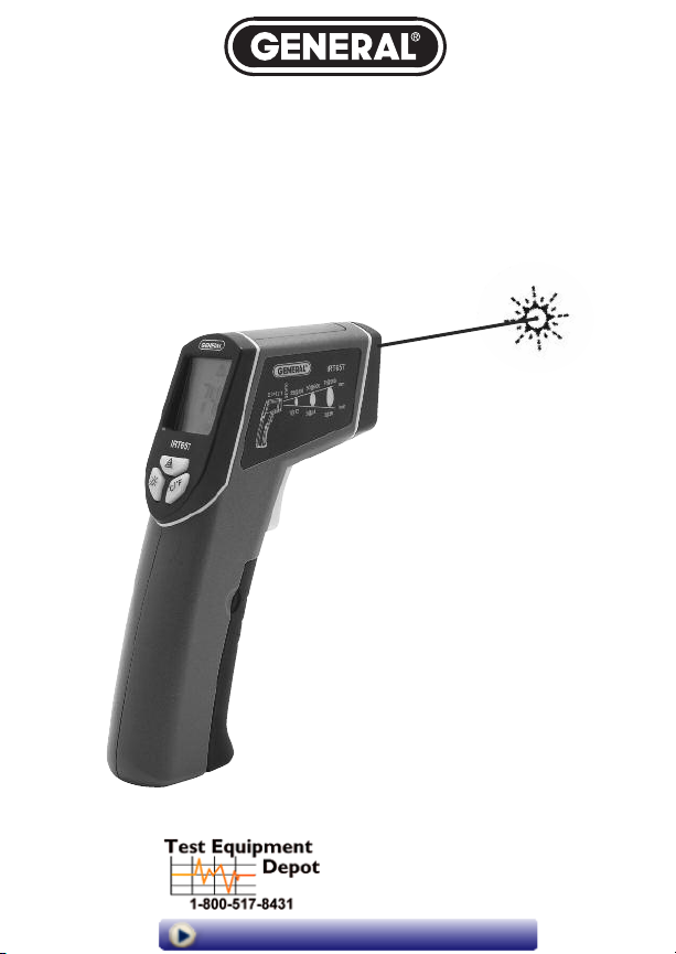
12:1 WIDE-RANGE
INFRARED THERMOMETER
WITH STAR BURST
LASER TARGETING
USER’S MANUAL
Star Burst Laser
Targeting
IRT657
99 Washington Street
Melrose, MA 02176
Phone 781-665-1400
Toll Free 1-800-517-8431
Visit us at www.TestEquipmentDepot.com
Page 2

TABLE OF CONTENTS
Introduction . . . . . . . . . . . . . . . . . . . . . . . . . . . . . 3 –4
Key Features . . . . . . . . . . . . . . . . . . . . . . . . . . . . . . . . 5
What’s in the Box . . . . . . . . . . . . . . . . . . . . . . . . . . . . 5
Product Overview . . . . . . . . . . . . . . . . . . . . . . . . . 5 –7
Setup Instructions . . . . . . . . . . . . . . . . . . . . . . . . . . . 7
Installing the Battery . . . . . . . . . . . . . . . . . . . . . . 7
Operating Instructions . . . . . . . . . . . . . . . . . . . . 8 – 11
How To Make Accurate IR Measurements . . 9 – 11
Specifications . . . . . . . . . . . . . . . . . . . . . . . . . . . . . . 12
Maintenance and Troubleshooting Tips . . . . . . . . . 13
Warranty Information . . . . . . . . . . . . . . . . . . . . . . . . 14
Return for Repair Policy . . . . . . . . . . . . . . . . . . . . . . 15
Manual del Usuario . . . . . . . . . . . . . . . . . . . . . 16 – 30
Manuel de L'Utilisateur . . . . . . . . . . . . . . . . . . 31 – 45
2
Page 3

INTRODUCTION
Thank you for purchasing General Tools & Instruments’ IRT657
12:1 Wide Range Infrared Thermometer with Star Burst Laser
Targeting. Please read this user’s manual carefully and thoroughly
before using the thermometer.
The IRT657 is a compact, non-contact (infrared) thermometer
with a 12:1 distance-to-spot (D:S) ratio and a wide measurement
range of -40° to 1076°F (-40° to 580°C). These two key
specifications make the IRT657 ideal for various applications,
a few of which are listed below.
Using this IR thermometer, the temperature of a target can easily
be measured from a distance. This makes it possible to safely
measure the temperature of very hot or cold surfaces, hard-toreach objects and toxic substances.
The IRT657 is especially suitable for the following four classes of
applications:
ELECTRICAL
• Checking the temperature of high-voltage equipment and
transformers from a safe distance
• Detecting excessive heating of motors, fuses, wires, insulators,
connectors, and switches
• Pinpointing hot spots in electrical connections and bearings
• Verifying temperatures of induction-heated parts
HVAC/R
• Monitoring food processing and storage temperatures
• Checking heating, AC and refrigeration system components
• Taking the temperature of forced hot air supply and return vents
• Testing chillers, steam traps and heat exchangers
3
Page 4

INDUSTRIAL/MRO
• Making temperature measurements on equipment during
maintenance, repair and operations (MRO)
• Performance testing of motors, turbomachinery and boilers,
including identifying overheated bearings, couplings and
conveyor belts
• Simplifying jobs such as laying asphalt or concrete and
checking fire protection systems
AUTOMOTIVE
• Detecting overheated electrical components, connectors and
wiring harnesses
• Pinpointing radiator core restrictions
• Testing temperature sensors, catalytic converters and exhaust
systems
• Measuring the temperature of oil, batteries, A/C systems and
tire treads
The IRT657 has a backlit LCD and is powered by a single 9V
battery. Thanks to the instrument’s auto power off feature, the
battery may last up to 50 hours when the backlight and laser
pointer are turned off.
CAUTION!
The IRT657 is a Class 3R laser product that emits less than 3mW
of radiation. Avoid looking directly at the laser pointer. U.S. law
prohibits pointing a laser beam at aircraft; doing so is punishable
by a fine of up to $10,000 and imprisonment.
4
Page 5

KEY FEATURES
• Measurement range of -40° to 1076°F (-40° to 580°C)
• 12:1 distance-to-spot (D:S) ratio
• Emissivity fixed at 0.95
• Measurements accurate within ±3°F (2°C) or ±2% of reading
(whichever is greater) for readings above 32°F (0°C); within
±5°F (3°C) or ±2% of reading (whichever is greater) for
readings below 32°F (0°C)
• °F or °C unit selectable on front panel
• Large (1.6 in. diagonal) backlit LCD
• Low (<30mA) power consumption when laser and backlight are
off; extends battery life
• Meets CE, RoHS and U.S. FDA standards
CAUTION: Use of controls or adjustments or performance of
procedures other than those specified herein may result in
dangerous radiation exposure.
WHAT’S IN THE BOX
The IRT657 comes in a blister pack along with a soft carrying
case, a 9V battery and this user’s manual.
PRODUCT OVERVIEW
Figure 1 shows all of the controls, indicators and physical features
of the IRT657. Figure 2 shows most of the icons and text that may
appear on the display. Familiarize yourself with the locations and
functions of these controls and the meanings of these display
icons before moving on to the setup and operating instructions.
5
Page 6

Fig 1. The IRT657’s controls, indicators and physical features
A
B
C
D
A. Laser Pointer
B. Infrared Sensor/Lens
C. Measurement Trigger
D. Battery Compartment
E. Backlit Liquid-Crystal
Display
F. Button (laser on or off)
I
E
F
G
H
G. Button
(backlight on or off)
H. °C/°F Button (temperature
unit selection)
I. Laser Identification/
Certification/Warning/Safety
Labels (on left side); see
below
6
Page 7

A
D
E
B
C
F
G
Fig. 2. All possible display indications
A. Low battery
B. Measured temperature
C. Measurement in progress
D. Laser on
E. Fahrenheit units selected
F. Celsius units selected
G. Data being held (for 7 seconds, max, after trigger is released)
SETUP INSTRUCTIONS
INSTALLING THE BATTERY
Open the battery compartment (callout D of Fig. 1) by pulling its
cover away from the grip. Then plug the 9V battery that comes
with the IRT657 into the wired socket inside the compartment.
The terminals of the battery and the socket mate in only one way,
with the smaller male terminal plugging into the larger female
terminal. Close the battery compartment by snapping it shut.
7
Page 8

OPERATING INSTRUCTIONS
To make a quick temperature measurement, squeeze the
measurement trigger on the front of the grip and hold it for at
least one second while pointing the laser at the target. Note that
the SCAN icon appears along with the measured temperature
while you are squeezing the trigger. When you release the trigger,
the SCAN icon disappears and is replaced by the HOLD icon for
no more than seven seconds. After seven seconds, the IRT657’s
auto power off function kicks in and shuts off the thermometer to
prevent battery discharge.
The IRT657 will not make accurate measurements if there is glass
or plastic between the thermometer and the target.
To change the IRT657’s default measurement unit from
degrees Celsius (°C) to degrees Fahrenheit (°F), press the °C/°F
button below the display at right to make the icon °F appear on
the right side of the display. To return to Celsius units, press the
°C/°F button again.
To turn off the backlight, press the button (callout G of
Fig. 1) below the display at left.
To turn off the laser pointer, press the button (callout F of
Fig. 1) below the center of the display.
8
Page 9

mm
S
inches
D
D:S=12:1
Fig. 3. The IRT657’s thermometer’s field of view
HOW TO MAKE ACCURATE IR
MEASUREMENTS
The IRT657 has a distance-to-spot (D:S) ratio of 12:1. This
means that the target area (spot) whose infrared radiation
(temperature) is being measured increases in diameter by
1 inch for every 12 inches you move away from the target.
Conversely, the diameter of the target area measured
decreases by 1 inch for every 12 inches you move closer
to the target.
All IR thermometers (IRTs), including the IRT657, take the
average temperature of all objects within a circular target
area (spot). Although the distance “D” in the D:S ratio is
defined as a linear value and the “S” defines the diameter
of the spot (see Fig. 3), the critical parameter is the target
area. Depending on the distance to the target (the object
whose temperature you want to measure), the target area
may include both the target and background objects near or
behind the thermometer’s field of view, which defines the
target area or spot.
9
Page 10

To explain the relationship between D:S ratio and
measurement accuracy, consider how the IRT657 would be
used to measure the temperature of a small AC motor
suspected of overheating. The motor measures
2
approximately 1 ft x 1 ft, so it has an area of 1 ft
. If the
IRT657 is used to make the measurement from 24 ft.
away, the reading will have a large error. At this distance,
2
the target area is 2 ft
. Therefore, the IRT657 will measure
not just the temperature of the motor, but also the
temperature of the physical surroundings in its field of
view, and average the two readings.
How inaccurate would the measurement be? If the motor’s
operating temperature is 200°F and the background
temperature is 75°F, and the motor’s area is half the target
area at the measurement distance, the following equation
gives the average temperature of the target area:
Tavg = (Tmotor + Tbackground) ÷ 2
Solving for Tavg, we get (200 + 75) ÷ 2 or 137.5°F., which
is what the IRT657 would display. In other words, trying to
measure the temperature of the motor from 24 ft. away
introduced an error of (200-137.5) ÷ 200, or 31% into the
measurement. In this case, the measured temperature was
31% below the motor’s actual temperature because the
background is cooler than the motor.
To eliminate measurement error, the IRT must be moved
close enough so the motor is the only object in the target
area (see Fig. 4). For a motor with an area of 1 ft
2
and
using an IRT with a D:S ratio of 12:1, the optimum
measurement distance would be 12 ft.
10
Page 11

For best results, the targeted area (spot) should fall within
the target’s boundaries, as in Fig. 3
wall
Fig. 4. Measuring a motor’s temperature from the wrong
(top) and right (bottom) distance
11
Page 12

SPECIFICATIONS
Measurement Range -40° to 1076°F (-40° to 580°C)
Distance-To-Spot (D:S) Ratio 12:1
Measurement Accuracy ±3°F (2°C) or ±2% of reading
(whichever is greater) for readings
above 32°F (0°C); within ±5°F (3°C) or
±2% of reading (whichever is greater)
for readings below 32°F (0°C)
Measurement Repeatability 1% of reading or 1°
Response Time 250 msec for 95% response
Emissivity Fixed at 0.95
Laser Class/Power/Wavelength
Functions Controllable °F/°C temperature unit, backlight
from Front Panel on/off, laser pointer on/off
Auto Power Off Trigger Inactivity for 7 seconds
Current Consumption <30mA, max
Battery Life 50 hours (typical), w/backlight and
Operating Temperature 32° to 104°F (0° to 40°C)
Storage Temperature -4° to 140°F (-20° to 60°C)
Power Source One 9V battery
Dimensions 6.9 x 3.6 x 1.5 in.
Weight 5.93 oz. (168g)
Class 3R<3mW/655nm
laser pointer off
@ <75% relative humidity (RH)
@<85% RH
(175.3 x 92.1 x 38.1mm)
12
Page 13

MAINTENANCE AND
TROUBLESHOOTING TIPS
After subjecting the thermometer to a sudden change in ambient
temperature, you must wait 30 minutes before measurements are
within specifications.
The infrared lens on the front of the unit is the IRT657’s most
sensitive component. To clean the lens, first use compressed air to
blow off loose particles and then brush any remaining debris
away with a camel’s hair brush. If necessary, carefully wipe the
lens with a cotton swab moistened with water. NEVER use a
solvent, such as alcohol, to clean the lens.
To clean the thermometer’s housing, use soap and water and a
sponge or soft cloth.
When the icon appears in the upper left corner of the
display, it’s time to change the thermometer’s 9V battery. To do so,
refer to the Setup Instructions on p. 7.
If the text “OH—“ or “OL” appears on the display, the target’s
temperature is outside the measurement range of the IRT657.
If a temperature reading is far different than the known
temperature of a target, the likely reason is either:
• The thermometer is at the wrong distance from the target
(see “HOW TO MAKE ACCURATE IR MEASUREMENTS” on p. 9).
• The target’s emissivity is well below the IRT657’s fixed setting
of 0.95.
13
Page 14

WARRANTY INFORMATION
General Tools & Instruments’ (General’s) IRT657 12:1 Wide-Range
Infrared Thermometer with Star Burst Laser Targeting is
warranted to the original purchaser to be free from defects in
material and workmanship for a period of one year. Subject to
certain restrictions, General will repair or replace this instrument
if, after examination, the company determines it to be defective
in material or workmanship. The warranty period begins on the
date of purchase. You are encouraged to register your product
online. General will extend your warranty an additional 60 days if
you register at www.generaltools.com/Product Registry.
This warranty does not apply to damages that General determines
to be from an attempted repair by non-authorized personnel or
misuse, alterations, normal wear and tear, or accidental damage.
The defective unit must be returned to General Tools &
Instruments or to a General-authorized service center, freight
prepaid and insured.
Acceptance of the exclusive repair and replacement remedies
described herein is a condition of the contract for purchase of this
product. In no event shall General be liable for any incidental,
special, consequential or punitive damages, or for any cost,
attorneys’ fees, expenses, or losses alleged to be a consequence
of any damage due to failure of, or defect in any product
including, but not limited to, any claims for loss of profits.
Register now at www.generaltools.com/ProductRegistry to receive
a 60-day extension to your warranty.
14
Page 15

RETURN FOR REPAIR POLICY
Every effort has been made to provide you with a reliable product
of superior quality. However, in the event your instrument requires
repair, please contact our Customer Service to obtain an RGA
(Return Goods Authorization) number before forwarding the unit
via prepaid freight to the attention of our Service Center at this
address:
Remember to include a copy of your proof of purchase, your
return address, and your phone number and/or e-mail address.
15
Page 16

NOTES
________________________________________________
________________________________________________
________________________________________________
________________________________________________
________________________________________________
________________________________________________
________________________________________________
________________________________________________
________________________________________________
________________________________________________
________________________________________________
________________________________________________
________________________________________________
________________________________________________
________________________________________________
________________________________________________
46
Page 17

NOTES
________________________________________________
________________________________________________
________________________________________________
________________________________________________
________________________________________________
________________________________________________
________________________________________________
________________________________________________
________________________________________________
________________________________________________
________________________________________________
________________________________________________
________________________________________________
________________________________________________
________________________________________________
________________________________________________
47
Page 18

General Tools & Instruments
GeneralToolsNYC
99 Washington Street
Melrose, MA 02176
Phone 781-665-1400
Toll Free 1-800-517-8431
Visit us at www.TestEquipmentDepot.com
Specifications subject to change without notice
NOTICE - WE ARE NOT RESPONSIBLE FOR TYPOGRAPHICAL ERRORS.
©2015 GENERAL TOOLS & INSTRUMENTS
MAN# IRT657
5/26/15
 Loading...