

Page 1
la
d,
=
E
ho
tr'l
D
661
7J
Eur
-rA
<o
fi=
z
rI
o
F"."froToFACT*
FolJ"t
GENERAL
moDEr
INDUSTRIES
25()
o
Itt
z
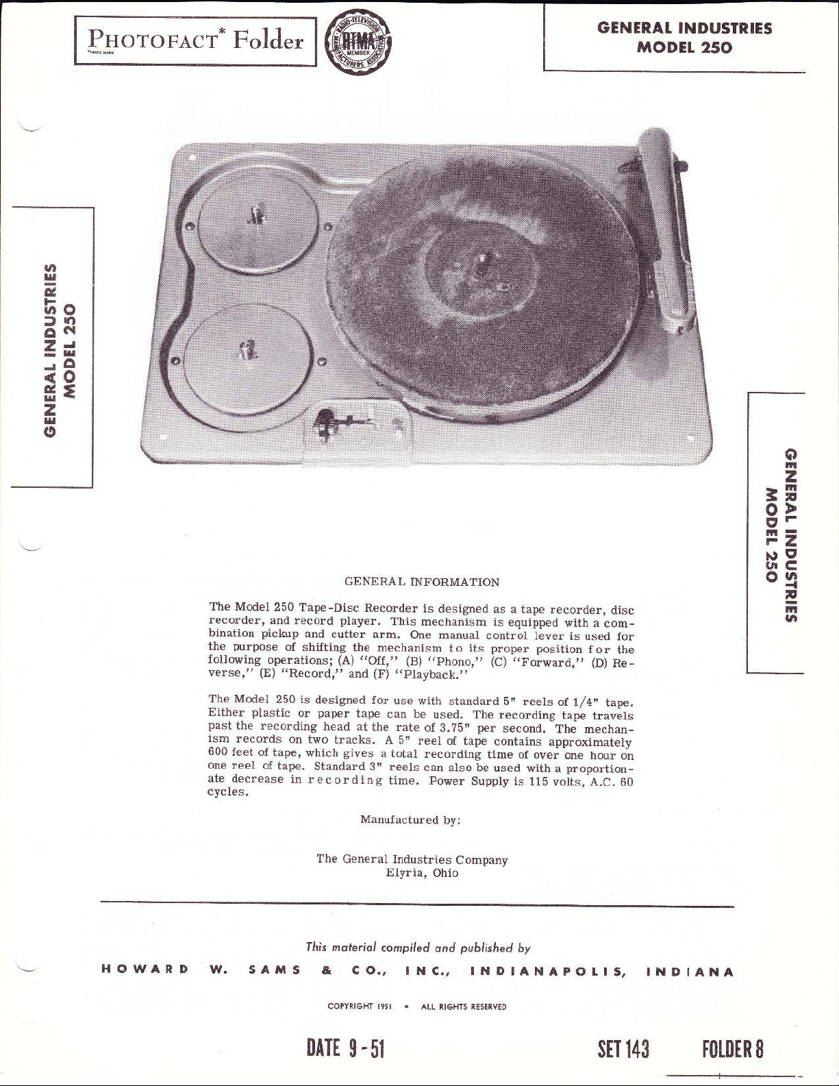
The Model
recorder,
bination
prrpose
the
following.
verse,"
The
Model
Either
past
ism
600
one
ate
cycles.
plastic
the recording
records
feet
of
reel
decrease
250
Tape-Disc
and
record
pickup
(E)
and
of
shifting
operations;
"Record,"
250 is
or
on
two
tape,
of
which
tape.
in
recording
GENERAL
player.
cutter
the
(A)
and
designed
paper
tape
head
at
tracks.
gives
Standard
The
General
INFORMATION
Recorder
arm.
mechanism
,,Off:,
(F)
for
the
a
3n
is
This
mechanism
One
,,phono,,,
(B)
,,playback.',
use
with
can
be
rate
of
A
bn
reel
total
recording
reels
can
time.
Manufactured
Industries
Elyria,
designed
manual
o its
t
standard
used.
3.?b"
of tape
also be
power
by:
Company
Ohio
as
a
is
equipped
control
proper
,,Forward,,'
(C)
br reels
The
recording
per
second.
contains
time
of
used
supply is
tape recorder,
with
lever
is
position
of.
tape
-The
approximately
ovei
one
proportion-
with
a
llb
voits,
a
used
f
o r
(D)
l/4"
travels
mechan-
hour
A.c.60
disc
com-
for
the
Re_
tape.
on
OD
=F
gr
m=
F1
xrEl
UtC
oa
{
2
TT
ta
HGWARD
l^f.
sAxl
fhis
5
0ATE
moferiol
&
COPYRIGHT
g
co.,
5l
compiled
I
NC., INDIANAPOIlS,
o
l95l
ALL
published
ond
RIGHTS RESERVED
by
sET
INDIANA
t43
t0rDtR
8
Page 2

OPERATING INSTRUCTIONS
Threading of
(a)
plastic
pan
(32)
sure
of
the reel.
making
of
the
approximately
around
the hub
taken
tape is
contact
ready
Recording
To record
ward,
with
then
safety
engagement
position.
When
contacts
only
recording
Place a reel
paper
or
with one
the magnetic
(b)
Place
sure
spindle.
(c)
Grasp the
t}te
turntable
of
the front reel.
up by
tightened, it
the rubber
for
operation.
-
on
slightly,
the
"Record"
pushed
forward
button
in
the
the recording
at the instant
head
Tape
-
(3n
base recording
of
slot
the empty
the
coating
that the slot
free
three feet of
and
the free end is
turning
the tape, move
the front reel
will
capstan
and then
slide under
to the right, until it is
position.
(42)
of
and,
pulled
is
the control knob
"Record"
tape and erases
just
(2?).
Only the lower
or 5"
diameter)
tape on the
reel
engaging
of
the tape faces the
reel
on the front
in
reel
the
end of the
engages the key
tape
tape. The
The slack in
clockwise.
the
(?4).
The recorder is
the control knob
The
at the same
position,
prior
control knob
f orward
(a2)
the
passing
to
time, the
in
track of the tape
of either
rear
reel
(31).
key
center
pan,
reel
and unwind
placed
is
tape
threaded into
the tape is
turntable
to
the
erase head
the lowertrack
When
(43)
aligned
(43)
record
permit
"Reeord"
over
and
now
for-
Be
full
(35)
the
half
one,
played
of the tape,
must be
back.
the
removed from the
transferred to the rear reel
that the slot
must
in
be
the tap€, as
with
recording in
the
-
tape
to the start of
position
o
t
control knob
The recorder
the Recorder
may be
to the
the
into
-
stopped
position
is
now rewinding.
at any
-
the tape to t}e start
on
"To
Rewind");
If both tracks
played
be
to
to remove
reel
the
the reels
pans,
as
described
control knob
will now operate
front reel,
reel engages
tfie
transferred
previously
the same
the recording,
marked
the reverse
point
marked
from
"Off."
of
that
recording
the
is,
if one track
have been recorded
the start,
and transfer
under
3'Playback"
to the
for
record
to
is
the
the
now
turned
pan,
key
front
and
which
pan,
to
described,
manner.
shift
"Reverse."
slot as far as
by shifting the
(see
only
it
will be
them to
"Record-
playback.
posi-
is recorded or
Whenthe rear reel is emptyand it isdesired
the upper
full
the
completely over, and
making
(31).
pan.
proceed
To Rewind
To rewind the
sure
The empty reel
Thread
the control knob
Push the
possible.
To Stop
The tape
control
is
Playback
Reurind
paragraph
has been recorded.
and the tape is
necessary
the
ing."
knob
opposite
Move
tion. The recorder
Page
2
Page 3

To
Repair
In case
to edit
tape.
adhesive
Scotch
coated,
splice
or a
the recording
without interference.
Fast-Forward
If
a recording
tape
the
To Play
play
To
tion
With
function
rear
tape,
tate
of
the
back
is
held
Cutting
To
the
or
Sp1ice
the
a recording,
tape
is
Do not use
material is
tape
should be
side of
should be
the recording
trimmed with a
knife, to bring
tape so
-
near
may
be speeded
('Forward"
Standard
?8
the
control
the
shift
reel
and
the
turntable.
pickup
needle
in
Disc
cut
home
playback
position.
RPM
control
lever
clutches.
the
only function
arm
is inserted
position
Recordings
recordings,
needle from
records,
knob
Tape
-
broken
accidentally,
4 splice may
medicated
not
suited
applied
the width of
pass
it
will
the end
up by
78
RPM
knob in
(a1)
of
moving
Records
it
is
(43)
in
the
depresses
This eliminates
the
playing
In
(4)
with
is
depressed;
in
the
needle
-
records,
it is
the cartridge
be
made
adhesive
to this
to
the reverse,
tape.
The edges of
small
the splice
the
the
tape is
the
-
only
necessary
,,phono,'
the
',phono"
both
the
performs
unit
a
pickup
thumb
screw.
necessary
is
or it
desired
with
tape
purpose.
pair
of
scissors,
various
to that of
contacts
desired,
control knob
to
position.
position,
the front
driving of
is
the rear
standard
cartridge
to remove
(6)
and insert
Scotch
as
the
The
or
un-
the
the
posi-
the
and
the
to ro-
portion
play-
(6)
and
a
blank on
the
ing
of
edge
tion
of the
right
the
the
This
follower
recording
the
to
tion. If
place
The drive
motor
ing
and
turn,
to the
shaft.
Operation
.off,t
When the control
the
knob,
(63),
standardS/8"
the turntable
turntable
disc.
the record.
of the
at which
pickup
side of
llp
through
Raise
recording
the recording
arm
the arm.
on
the
lock spring
holds
the
(83)
arm
is
tape,
being
move
the recording
the
control
MECHANICAL
mechanism
(61),
and
drives
drive
of
Position
which
the
the
pulley
the
mechanism
(51)
shift lever
is moved
shutting
off
recording
the hole
pickup
the
Place
the
by
lifting
rear
of
of
the
arm
arm
in
to
engage
done
the
control
knob
drives'both
through
drive
capstan
(60)
Control
knob
(41),
which
against
the
motor
stylus.
with
the record
provided
arm
and
recording
blank
at
the
is
to
on
The arm
the
is
in
inpludes
which is
(43)
the
the ear
follower
lock
bracket
a
raised position
the
some
knob
t o be
,.playback,,
the
FUNCTION
lead
from
the following:
the turntable"and
the
media
pulley
(6b).
(?4).
These
fastened
(4S)
Knob
is
in
is
fastened
pin
of
power.
place
move
stylus
approximate
start.
extending
should
be raised
arm
assembly
screw
source
,rphono,
to
the
made
from
of
drive
The
belts
,,Off',
the
t o the
the
switch
a recording
driving
in
the record-
it
to the
on
the
Raise
the rear
(82)
engages
causing
(?g).
other
the
position.
A
belts
turntable,
are
coupled
to the
position,
control
assembly
pin
edge
outer
loca-
to the
until
(80).
the
if
the
than
posi_
1ape,
single
re6l-
(b0)
in
motor
o
F
z
35
o>
gF
li=
F1
|\r9
lrr
of
C
oa
{
?
trl
UI
Page
3
Page 4

Page
4
Page 5

*r
<@
0a
}/o
hr
!>
k
d06
x2
EE
ltJ
:o
tn
E
)c
uJ
o-
III
cx
I
:
lrt
oa
xlI
tl
tn
2
C
-l
F1
Et=
gr
=Fo>
z
o
llt
Page 6

ttPhono"
With the control knob
shift lever
(63).
against the
which
ing
actuating
pin (40)
ord and
"Reverse
When the shift lever
position,
the front reel from the clutch assembly. The
engages
ism
For
reversed.
to
playback
The Fast Forward
to the
positions
(14), pressure pad
tape
jEecqA
When
"Playback"
Position
(a1)
is
-
moved
The switch actuator
pin,
switch
on
turns
(40)
lever
is actuated by spring
lever
by the shift
Playbaek"
and
Forward"
it
depresses
the clutch spring, thus
for
Fast Rewind.
Forward,
Fast
The Forward
1
over the
3
-3/4"
tape speed.
fact that when the shift
-
"Forward
gives
which
Pt"VnactL
""4
the control
position,
motor
the
(40)
is
lever
positions.
the
per
and
and spring
free
knob
tilting the
(a1)
movement
('Phono"
in
the
away from
lever
mercury
power.
pushed
away
(al)
when
Positions
is moved to the
the lift
position
lever
operating the
of the
speed
second
Rewind
-
(43)
the shift
normal recording
are accomplished due
lever
Reverse," the
(18)
to
is in
lever
position,
the switch
(40)
then
The switch
switch
(62).
from t h e switch
in
the
-
(58)
disengaging
reel
is
approximately
(41)
pinch
do not
reels.
either
"Record"
(al)
contacts
the
pin
moves
(63A)
actuat-
The switch
-Rec-
"Off
"Reverse"
pan
rear
mechan-
pans
are
is
in these
roller
contact
the
the
pressure
spring
(14)in
roller
capstan
part
of
recording
ing head
driving
recording tape firmly
part
is
(?4)
is,
acts
as
"wow"
tape.
Automatic
When
back"
ing
20
or
or
lever
tension
positionl
forward
in
such
automatically
Mechanism
broken.
pad
(21) (see
(74).
this assembly,
tape and is held
(2?).
capstan and the
of
the recording head.
in
turn, driven by
a f lywheel,
effect as
Shut Off
pinch
and
Figure 2).
firm
contact with the tape and the driving
pressure
The
is
This assures firm
against
thus minimizing any flutter or
a result of
-
the mechansim
position,
of
a manner
t.
the
(40)
the tape then
however, when
reel,
shift
are
moved clear of
the mercury switch
as to open
stopping
TROUBLES AND
Does Not Turn
Switch
actuating
roller assembly actuating
brings
This
(18),
pad
brought into
firmly
tape, as well a s
the
contact
against
contact
r€cording
The driving
the large turntable,
changing velocity of the
is
in the
"Record"
(41)
lever
holds
aII
the
the unit.
ADJUSTMENTS
On
and
the
switch
the switch
is wound
tape
permitted
is
motor circuit,
the
in
Position
'
spring
(62)
which
switch
pinch
the
is also
with the
the record-
between the
holding
gap,
which
capstan
which
or
"PIay-
actuat-
(63).
(
in the
on the
-
loose
the
The
.On"
to
thus
tip
or
Page
6
Page 7

(a)
Switch
to the
actuating
switch
actuating
actuating lever
switch to the
(62).
spring
Turntable Rotates
1. Mercury
direction.
switch bracket and reverse
Reel
Pans
Remove
(32)
Fail to
1. Lift levers
(a)
In the
pan
must be raised to the
the
clears
the front
clutch spiing
clear the lower end
by approximately 1f32" to
the lift lever
section of the
front reel
1/16n clearance is obtained.
(b)
In reverse, the
and the front
(69)
lever
above, leaving a clearance
NOTE: In the
"Record"
the lift levers
pan
reel
tact the clutch
Fails to Record or
1. Pressure
(a)
Checkthe screws thathold
spring
they are tight.
(18)
2. Pressure
"On"
in
"Off
switch
mercury switctr
Rotate
(58)
"Forward-Speed"
clutch
pan
must be
(49),
(58),
lever immediately
pan
shaft
pan
in
the same
(58)
shafts
so
springs
Playback Properly
pad
spring
to the mounting
pad
worn or missing.
spring
(40)
Position but will
its
and
must be connected
(40)
lever
may tilt the
position.
(63.{)
turned
(63A)
position (see
to Wind the
(69)
out of adjustment.
position,
so
mercury
Replace
not
from
Tape -
position
(48).
spring
and the lift lever
of the front reel
At the same
Lowered
contact the
to
1/16". To
bend the short unf
until a
rear reel
space
pan
of
is lowered
is raised. Adjust the
manner as described
of.1f32" to l/16.'
and
"Playback"
(69)
and
that both the
must elear
(48)
and
(18)
loose.
plate
pans
(a9).
-
pressure pad
the
(15)
that the
the
in wrong
clip of
Figure 3).
rear
the
so that
time,
(58)
must
pan
shaft
adjust
Iange d
under the
l/32"
lift
positions,
both
will
con-
to see if
allowlng
mounting
plate
ttRecordt'
the spring to slip
plate (15),
will not be
or
pivoted
t'Playbackt'
turn, the tape will not
stan and
lWowj'
lgftng
1. Follower
(?3) properly.
pickup
engage
pickup
it
to
arm
ment should
pickup
the
point
of engagement,it can be
bending
engages the
will
in
heavy,
result
the
and continuous
The
ufacture,
of time;
the follower arm
put
be
recording.
the
there
of the follower arm
lead screw
recorder
however, if the unit is used to
recording head.
Disc Reco"di"g
(83)
arm
When lifting the rear section
arm assembly, the
the lead screw
in
locks
be at a
arm locks. If
lead
screw too
on the
(?3)
raised
the
point
betwee\ tf 8"
it is
lead
screw,
If the engagement
possibllity
is
a
rather than moving along
pattern.
LUBRICATION
has been lubricated at time of
unit
which should be sufficient
or is subjected to extreme
be cleaned with carbon tetrachloride
should
as follows:
cated
t.
lubricate
(52),
To
and reel
pan
Remove the
end of the reel shaft,
(32)
and clutch springs
ine. Place
on the reel shaft and the
ing. Place
inthe
countersunk
next to the
the felt
60 oil.
SAE
the
clutch springs
"C"
or three drops of
two
five
porous
pads
on the clutch springs with
over
pinch
the
position.
be held against the cap-
not engaging
follower arm
before the rear
position.
necessary
accomplished byslightly
(83).
If the
tightly,
thus
grouping,
of
lifting up on
boss on the
the
roller mounting
inward
an
injecting
is
when
If
this
-
lead
screw
(83)
should
of the
engage-
This
lf 4 before
^nd
to adjust this
follower
excessive
which
the
"Wow"
threads
not sufficiently
in a smooth
great
recorder
the
and lubri-
off
the
SAE
of the
SAE
period
sheave
Saturate
for a Iong
heat or dust,
pan
reel
washer
or
six
portion
bronze bearing.
a
shaft, reel
(48-49):
(56)
and lift the reel
(48-a9)
inside
drops of
ofthe reel sheave
on the lower
in
is
of the
arm
load
is the
of
man-
extent
pan
mach-
10 oil
bear-
20 oil
o
m
z
=5o>
gF
!n=
F1
dE
ora
q
2
EI
gl
(a)
of adjustment, it may be
Remove the
Loosen
(1
7).
Set the
position.
Turn the adjusting
pressure
pad just
Then
wise
Replace the
(b)
If the
pad
and adjust
3.
Spring
(a)
If
the
broken
pressure pad
If the
pinch
the lock nut on
shift lever
pad
spring
contacts
turn the screw
and tighten
pressure pad
(21)
pressure pad
the
pinch
as above.
loose
or the mounting
is
worn some
corrected as follows:
cover
(tr1).
roller
the adjusting screw
(41)
in
the
"Rec
(1?)
screw
(18)
until
in
against
the
pressure
the recording head
ll2to3/4 turn clock-
lock
nut.
cover
(11).
spring
(19)
is
roller
is
missing, replace
broken.
or
actuating
screw
or is
ord"
the
(2?).
the
(21)
loose,
pad.
out
CAUTION:
Do not oversaturate the f elt
avoid overlubrication of all
much
oil may come
in
contact with the
parts,
Also
as too
rubber drive surfaces of the drive mech-
anism, causing
"Wow."
2. To lubricate the turntable drive wheel
(26):
shaft
thb
SAE
place
rubber
10
and
Move
the machine
drive
go.
it will
oil on the
(9).
Raise the
put
two or three
post
the
post.
Page
wheel
Plare
wherl
up
?
and
Remove
on its
(26)
one or
shaft.
Pivot
pickup
drops of SAE 20 oil on the
down
is
3.
arm
several times to equalize the oil on the
the turntable and
edge. Raise
in its
bearing as far as
two drops of
post (5)
its highest
to
and bushing
position
post.
Page 8

PARTS LIfiT
Ref .
No.
1
2
3
4
5
6
7
B
I
10
11
t2
13
L4
15
16
t1
1B
19
20
2l
22
23
24
25
26
27
28
29
30
31
32
33
33A
34
35
36
3?
38
Part
No.
64419
11509
1620?
25t49
25108
2 5113
12098
25168
25126
22903
25193
21914
21844
25186
251 91
30214
115?8
25182
12129
25t71
251 78
11598
25r32
25131
25t57
25049
251 16
22376
58?1
25034
25036
25039
25003
25147
25t61
25072
251
25't2t
2
5119
Description
Turntable
Set Screw
Lock
Nut
Tone
Arm
Pivot
Shaft
Pickup
Cartridge
Felt Washer
Tone Arm
Pinch RoIIer Cover
Mounting Screws
Pinch
Roller
Hairpin
Fiber Washer
Pinch
Roller
Pinch
Roller
Stud
Assembly
Spring
PIate
Pad Adjustment Screw
Felt
Felt Pressure Pad and
Spring
Screw
Shoulder Washer
Pressure Pad
Screw,
Recording Head
Tape
Guide
Rubber Bushing
Tape
Washer for Tape
Turntable Drive Wheel
Recording Head
Screw,
Sub-Chassis
Screw,
Sleeve
Assembly
Key
Lug used on
Platform
Disc
Plate
Platform
Base Plate
Tone Arm
Screw,
Head
Erase
18
Spring
Recording
Spring
Shoulder
Complete
Assembly
Cartridge
Mounting
Pivot Post
Shure
-
Screw
Bushing
Plate
Plate
Cover
Clip
Hub and Tire
Mounting Plate and
for Pinch
Roller
Mounting
Assembly
Actuating
used for Mounting
Post
used on
Post
Guide
Guide
Post
used to Mount Motor
used
to Mount
Bushing
Disc Plate
for
Reel Plafform
Reel
Assembly
used
on
Reel
Assembly
Rest
used for
Head
Mounting Erase
Clip used with
Head
Clip
Washer
P89R
ing
Spring
Ref .
No.
39
40
4l
42
43
44
45
46
41
48
49
50
51
52
53
54
55
56
57
58
59
60
61
62
63
63A
64
65
66
61
6B
69
?0
1t
72
?3
74
75
?6
77
?8
79
80
B1
82
83
Part
No.
22903
25122
25134
251 51
25r46
3119
14463
25176
25174
25029
25031
25019
2501 3
25031
2286r
25121
25091
25084
22903
25028
23235
25r24
2506?
25129
25054
25044
25119
2286t
25056
25084
25OBB
13823
21934
21933
25077
7534
9569
250?9
22903
25166
25102
25153
22376
25098
Description
Screw, used
Auxiliary
Switch Actuator
Function
for Mounting
Shaft Housing
Lever
Switch Lever
Safety Button
Control Knob
Lockwasher, used
Hex Nut
Keyed Washer
Washer
Clutch
Clutch
Reel
Plate
Plate
Drive Belt
on Control Knob
Assembly
Rear
Assembly
Front
Turntable Drive Belt
Reel Pan and
Clutch Drive
Sub-Chassis
Reel Shaft
Nut,
ttC"
used to
Washer
Mount
Sub-Chassis
Spring, used with LiJt Lever
LiJt
Lever
Screw,
used
to
Mount
Drive Pulley
Pulley
Drive
Motor
Spring, Switch
Shut-off Switch
(Iess
Mercury
Actuating
Assembly
Switch)
Mercury Switch
Drive Wheel
Bearing
Plate and
Assembly
Drive Pulley
Shoulder Washer
Hex Nut
Set Screw
LiJt Lever
Tri-Mount Stud, Lift
Lever Mounting
Lock
Nut for Lead Screw
End
Thrust Screw for Lead Screw
Lead
Screw and Gear
Turntable Shaft and
Lock
Screw
for Turntable
Assembly
Capstan
Shaft and Capstan
Lock
Nut
Auxiliary
Adjusting
Reinforcing
Arm
Lock
Shaft Housing
Screw, Shaft Housing
Plate
Lock Bracket
Arm
Nut,
Assembly
Bracket
Assembly
Lock Screw, Follower Arm
Follower Arm
Sheave
 Loading...