

Page 1

General HP
40W
Printed In Malaysia
A38251614A
PD001216
Full Channel AM/FM
Amateur Mobile Transceiver
OWNER'S
MANUAL
Downloaded from www.cbradio.nl
Page 2
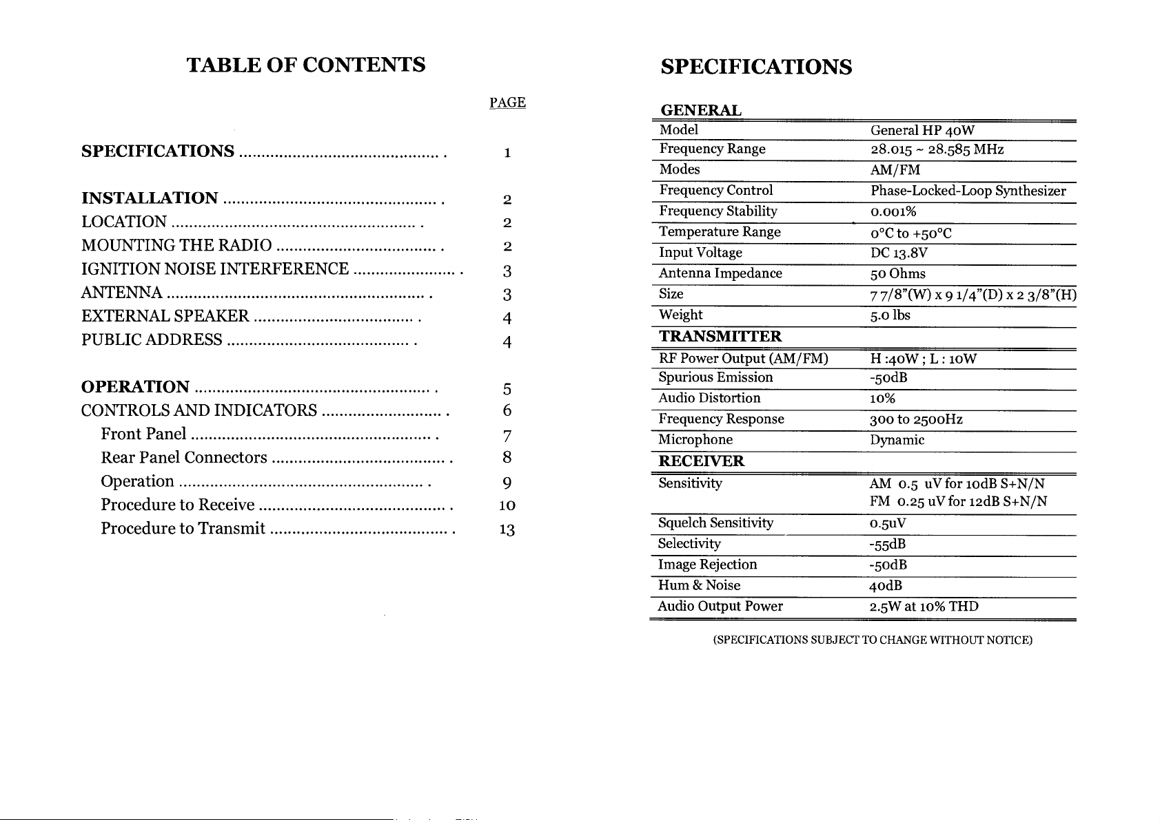
TABLE OF CONTENTS
SPECIFICATIONS
SPECIFICATIONS
INSTALLATION
LOCATION
MOUNTING THE RADIO
IGNITION NOISE INTERFERENCE
ANTENNA
EXTERNAL SPEAKER
PUBLIC ADDRESS
OPERATION
CONTROLS AND INDICATORS
Front Panel
Rear Panel Connectors
Operation
Procedure to Receive
Procedure to Transmit
PAGE
1
2
2
2
3
3
4
4
5
6
7
8
9
10
13
GENERAL
Model
Frequency Range
Modes
Frequency Control
Frequency Stability
Temperature Range
Input Voltage
Antenna Impedance
Size
Weight
TRANSMITTER
RF Power Output (AM/FM)
Spurious Emission
Audio Distortion
Frequency Response
Microphone
RECEIVER
Sensitivity
Squelch Sensitivity
Selectivity
Image Rejection
Hum & Noise
Audio Output Power
General HP 40W
28.015 - 28.585 MHz
AM/FM
Phase-Locked-Loop Synthesizer
0.001%
o°C to +50°C
DC 13.8V
50 Ohms
7 7/8"(W) x 9 1/4"(D)
.olbs
H :40W; L: loW
-odB
10%
300 to 2500Hz
Dynamic
AM 0.5 uV for iodBS+N/N
FM 0.25 uVfor 12dB S+N/N
0.5uV
-odB
40dB
2.5W at io% THD
X
2 3/8"(H)
(SPECIFICATIONS SUBJECT TO CHANGE WITHOUT NOTICE)
Page 3

INSTALLATION
LOCATION
Plan the location of the transceiver and microphone
bracket before starting the installation. Select a location
that is convenient for operation and does not interfere
with the drive or passengers in the automobiles, the
transceiver is usually mounted the dash panel with the
microphone bracket beside it.
MOUNTING THE RADIO
The transceiver is supplied with a universal mounting
bracket. When mounting the bracket and radio to your car,
make sure it is mechanically strong. Also provide a good
electrical connection to the chassis of the vehicle. Proceed
as follows to mount the transceiver:
1.
After you have determined the most convenient
location in your vehicle, hold the transceiver with
mounting bracket in the exact location desired. If
nothing will interfere with mounting it in the desired
position remove the mounting bolts. Before drilling the
holes, make sure nothing will interfere with the
installation of the mounting bolts.
2.
Connect the antenna cable plug to the standard
receptacle on the rear panel. Most transceiver antennas
are terminated with a type PL-259 plug and mate with
the receptacle.
Connect the red DC power input wire (with the fuse) to
3.
+13.8V
automobile installation,
from the accessory contact on the ignition switch. This
prevent the set being left on accidentally when the
driver leaves the car and also permits operating the
unit without the engine running. Locate the accessory
contact on most ignition switches by tracing the power
wire from the AM broadcast receiver in the car.
DC. This wire extends from the rear panel. In
+13.8V
DC is usually obtained
Connect the black lead to
4.
the chassis of the car. Any convenient location with
good electrical contact (remove paint) may be used.
Mount the microphone bracket on the right side of the
5.
transceiver, using two screws supplied. When
mounting in an automobile, place the bracket under
the dash so that microphone is readily accessible.
—13.8V
DC. This is usually
IGNITION NOISE INTERFERENCE
Use of a mobile receiver at low signal levels is normally
limited by the presence of electrical noise. The primary
source of noise in automobile installation is from the
generator and ignition system in the vehicle. Under most
operating conditions, when signal level is adequate, the
background noise does not present a serious problem.
Also, when extremely low level signals are being received,
the transceiver may be operated with vehicles engine
turned off. The unit requires very little current and
therefore will not significantly discharge the vehicle
battery.
Even though the transceiver has ANL and NB controls, in
some installation ignition interference may be high
enough to make good communications impossible. The
electrical noise may come from several sources. Many
possibilities exist, as variations between vehicles require
different solutions to reduce the noise.
ANTENNA
A vertically polarized, quarter-wavelength whip antenna
provides the most reliable operation and greatest range.
Shorter, loaded-type whip antennas are more attractive,
compact and adequate for applications where the
maximum possible distance is not required. Also, loaded
whips do not present the problems of high wind resistant
imposed by a full quarter-wavelength whip.
Page 4

Mobile whip antennas utilize the metal body of the
vehicle as a ground plane. When mounted at a corner of
the vehicle they are slightly directional, in the direction of
the body of the vehicle. For all practical purpose, however,
the radiation pattern is nondirectional. The slight
directional characteristic will be observed only at extreme
distances. A standard antenna connector (type So-239) is
provided on the transceiver for easy connection to a
standard PL-259 cable termination.
If the transceiver is not mounted on a meta' surface, it is
necessary to run a separate ground wire from the unit to
good metal electrical ground in the vehicle. When installed
in a boat, the transceiver will not operate at maximum
efficiency without a ground plate, unless the vessel has a
steel hull.
Before installing the transceiver in a boat, consult your
dealer for information regarding an adequate grounding
system and prevention of electrolysis between fittings in
the hull and water.
EXTERNAL SPEAKER
The external speaker jack (EXT SP.) on the rear panel is
used for remote receiver monitoring. The external speaker
should have 8 ohms impedance and be able to handle at
least
watts. When the external speaker is plugged in, the
4
internal speaker is disconnected.
PUBLIC ADDRESS
To use the transceiver as a public address system,
connect an external 8 Ohms speaker
watts minimum)
(4
to the PA SP jack located on the rear panel. Direct speaker
aay from the microphone to prevent acoustic feedback.
Physical separation or isolation of the microphone and
speaker is important when operating the PA at high output
level.
OPERATION
CONTROLS
Front Panel
GENEPAL HP 40W
1
.
MICROPHONE
microphone for voice source.
2.
ON/OFF VOLUME CONTROL
apply power to the radio and to set the desired
listening level.
SQUELCH CONTROL : This switch is used to
3.
eliminate background noise being heard through the
receiver which can be disturbing when no signal is
being received. To use this feature of your radio, gently
turn the switch fully counterclockwise and then turn
clockwise until the background noise is just eliminated.
Further clockwise rotation will increase the threshold
level so that only strong signals will be heard.
MIC GAIN CONTROL
4.
in the transmit and PA modes. This controls the gain to
the extent that full talk power is available several
inches away from the microphone. In the Public
AND
NBANL
ANL
OFF )
VOL-S-SO MIC GAN-- RF
INDICATORS
GAIN
PA FM AM
c
0
JACK
: Adjust the microphone gain
E-TDNE
Used to
: Turn clockwise to
connect
-4
-5-
Page 5

Address (PA) mode, the control functions as the
volume control.
14.DIMMER SWITCH :
tower the level of brightness of display.
This switch is used to select
RF GAIN CONTROL :
5.
the gain of the RF amplifier under strong signal
conditions.
MODE CONTROL :
6.
one of the following operating modes: PA/FM/AM.
BAND SELECTOR :
7.
user to select the desired band.
E-TONE CONTROL :
8.
effect and intervals of echo sound.
CHANNEL SELECTOR :
9.
select a desired transmit and receive channel.
to. FRONT PANEL METER:
allows the user to monitor signal strength and RF
output power level.
11.
NB/ANL/OFF SWITCH :
switch. Move the switch all the way up to activate the
Noise Blanker (NB) and Automatic Noise Limiter
(ANL). The Noise Blanker is very effective in
eliminating repetitive impulse noise such as ignition
interference. When the switch is moved to the middle
position, only the Automatic Noise Limiter is engaged.
Move the switch to the bottom position to turn off the
ANL and NB.
This control is used to reduce
This control allows you to select
This band selector allow the
This control is used for echo
This control is used to
The front pane' meter
This is a three position
15.TX/RX LED :
the transmit mode. The green indicates the units is in
the receive mode.
16.CHANNEL DISPLAY :
indicates the current selected channel.
The red LED indicates the units is in
This channel display
12.RF POWER HI/LO SWITCH :
to select the HI or LO transmitting power.
13.T.B./OFF SWITCH :
the sound feedback effects.
This switch is used to monitor
This switch is used
Page 6

Rear Panel Connectors
-
0
ANT
PA
SP
o
00
o
0
MADE IN MALA
SIA
0
/
ANTENNA
1.
with a PL-259 type plug.
PA.
2.
SP.
operating, you must first connect a PA speaker (8 ohms,
4W) to this jack.
POWER
3.
built-in fuse. The power cord provided with the radio
has a black and red wire. The black goes to negative
and the red goes to positive
This jack accepts 50 ohms coaxial cable
:
: This jack is used for PA operation. Before
This accepts 13.8V DC power cable with
:
EXISP
PROCEDURE TO RECEIVE AND TRANSMIT
A.
MICROPHONE
The receiver and transmitter are controlled by the push-to-talk
switch on the microphone. Press the switch and the transmitter
is activated, release switch to receive. When transmitting, hold
the microphone two inches from the mouth and speak clearly in
a normal voice. This transceiver comes complete with a low
impedance dynamic microphone.
B. PROCEDURE TO RECEIVE
1.
Be sure that power source, microphone and antenna are
connected to the proper connectors before going to the next
step.
Turn VOL knob clockwise to apply power to the radio.
2.
Set the VOL for a comfortable listening level.
3.
Set the MODE switch to the desired mode.
4.
Listen to the background noise from the speaker. Turn the SQ
5.
knob slowly clockwise until the noise just disappears. The SQ
is now properly adjusted. The receiver will remain quiet until a
not advance the control too far
signal is actually received.
Do
or some of weaker signals will not be heard.
EXT SP.
4.
This jack accepts 4 to 8 ohm,
:
external speaker. When the external speaker is
connected to this jack, the built-in speaker will be
disabled.
F.C.
5.
: This connector is used for an external frequency
counter that indicates the frequency of the selected
channel.
watts
5
Set the CHANNEL selector switch to the desired channel.
6.
7.
Set the
RF GAIN
control fully clockwise for maximum RF
gain.
C. PROCEDURE TO TANSMIT
1. Select the desired channel of transmission
2. Set the
MIC GAIN
control fully clockwise.
Page 7

3. If the channel is clear, depress the push-to-talk switch on the
microphone and speak in a normal voice.
ALTERNATE MICROPHONES AND INSTALLATION
For best results, the user should select a low-impedance
dynamic type microphone or a transistorized microphone.
Transistorized type microphones have low output impedance
characteristics. The microphones must be provided with a five-
lead cable. The audio conductor and its shielded lead comprise
two of the leads. The third lead is for receive control, the fourth
is for grounding and fifth is for transmit control.
The microphone should provide the functions shown in
schematic below.
If the microphone to be used is provided with precut leads,
they must be revised as follows.
Cut leads so that they extend 7/16" beyond the plastic
1.
insulating jacket of the microphone cable.
All leads should be cut to the same length. Strip the ends of
2.
each wire 1/8" and tin the exposed wire.
Before beginning the actual wiring, read carefully the circuit
and wiring information provided with the microphone you select.
Use the minimum heat required in soldering the connections.
Keep the exposed wire lengths to a minimum to avoid shorting
when the microphone plug is reassembled.
5 WIRE MIC CABLE
Pin Number
2
3
4
Fig. 1 Your transceiver microphone schematic.
Mic Cable Lead
Audio Shield
Audio Lead
Transmit Control
Receive Control
KNURLED RING
PIN RECEPTACLE
RETAINING SCREW
A. MICROPHONE CONNECTOR ASSEMBLY
,- WASHER
CABLE CLAMP
RETAINER SCREW(2)
0
E=
-
.0.
B. MICROPHONE CONNECTOR DISASSEMBLED FOR WIRING
Fig. 2 Microphone plug wiring
Page 8

To wire the microphone cable to the plug provided, proceed as
follows
1.
Remove the retaining screw.
Unscrew the housing from the pin receptacle body.
2.
Loosen the two cable clamp retainer screws.
3.
Feed the microphone cable through the housing, knurled ring
4.
and washer as shown Figure 2.
The wires must now be soldered to the pins as indicated in the
5.
above wiring tables. If a vise or clamping tool is available it
should be used to hold the pin receptacle body during the
soldering operation, so that both hands are free to perform the
soldering. If a vise or clamping tool is not available, the pin
receptacle body can be held in a stationary position by inserting
it into the microphone jack on the front panel. The numbers of
the microphone plug are shown in Fig. 3, as viewed from the
back of the plug. Before soldering the wire to the pins, pre-tin
the wire receptacle of each pin of the plug.
make sure that it is placed on the threaded portion of the pin
receptacle body before soldering.
7.
If the microphone jack is used to hold the pin receptacle
during soldering operation, best results are obtained when the
connections to pin 1 and 3 are made first and then the
connections to pins 2, 4 and
soldering and be careful to prevent excessive solder
accumulation on pins, which could cause a short between the
pin and the microphone plug housing.
When all soldering connections to the pins of the microphone
8.
are completed, push the knurled ring and the housing forward
and screw the housing onto the threaded portion of the pin
receptacle body. Note the location of the screw clearance
hole in the plug housing with respect to the threaded hole in
the pin receptacle body. When the housing is completely
threaded into the pin receptacle body, a final fraction of a
turn either clockwise or counterclockwise may be required to
align the screw hole with the threaded hole in the pin
receptacle body. When these are aligned, the retaining screw
is then screwed into place to secure the housing to the pin
receptacle body.
Use a minimum amount of
5.
The two cable clamp retainer screws should now be tightened
9.
to secure the housing to the microphone cord. If the cutting
directions have been carefully followed, the cable clamp
should secure to the insulation jacket of the microphone
cable.
10.
Fig. 3
6. Be sure that the housing and the knurled ring of Figure 2 are
Microphone plug pin numbers viewed from rear of pin
receptacle.
pushed back onto the microphone cable before starting to
solder. If the washer is not captive to the pin receptacle body,
-
12 -
and secure the microphone plug in the transceiver.
Upon completion of the microphone plug wiring, connect
-
13
-
 Loading...