

Page 1
DIGITAL THERMOCOUPLE
THERMOMETERS
USER’S MANUAL
Please read this manual carefully and thoroughly before using this product.
DT8852
Dual input; compatible with
types “K”, “J” and “T” thermocouples
DT8855
Single input; compatible with
types “K”, “J”, “T”, “R”, “S” and “E” thermocouples
DT8856
Dual input; compatible with
types “K”, “J”, “T”, “R”, “S” and “E” thermocouples
Visit us at www.TestEquipmentDepot.com
99 Washington Street
Melrose, MA 02176
Phone 781-665-1400
Toll Free 1-800-517-8431
Page 2

TABLE OF CONTENTS
Introduction. . . . . . . . . . . . . . . . . . . . . . . . . . . . . . . . . . . . 2
Key Features. . . . . . . . . . . . . . . . . . . . . . . . . . . . . . . . 2 –3
What’s in the Case . . . . . . . . . . . . . . . . . . . . . . . . . . . . . . 3
Product Overview . . . . . . . . . . . . . . . . . . . . . . . . . . . . 3 –5
Setup Instructions. . . . . . . . . . . . . . . . . . . . . . . . . . . . 6 –7
Select Thermocouple Type . . . . . . . . . . . . . . . . . . . 6
Install Thermocouple(s) . . . . . . . . . . . . . . . . . . 6 –7
Operating Instructions. . . . . . . . . . . . . . . . . . . . . . . . 7 – 10
Monitoring Temperatures in Real Time. . . . . . . 7 –8
Making Relative Measurements. . . . . . . . . . . . . . . 8
Recording Min/Max Temperatures . . . . . . . . . . 8 –9
PC-assisted Data Logging . . . . . . . . . . . . . . . 9 – 10
Specifications . . . . . . . . . . . . . . . . . . . . . . . . . . . . . . . . . 10
Operating & Maintenance Tips . . . . . . . . . . . . . . . . . . . . 11
Warranty Information . . . . . . . . . . . . . . . . . . . . . . . . . . . 11
Return for Repair Policy . . . . . . . . . . . . . . . . . . . . . . . . . 12
Manuel de L'Utilisateur. . . . . . . . . . . . . . . . . . . . . . 13 – 24
Manual del Usuario . . . . . . . . . . . . . . . . . . . . . . . . . 25 – 36
INTRODUCTION
Thank you for purchasing General Tools & Instruments’ DT8852,
DT8855 or DT8856 Digital Thermocouple Thermometer. Please read
this user’s manual carefully and thoroughly before using the
instrument.
All three models are designed for precision temperature measurement.
They are also available for purchase with a National Institute of
Standards and Technology (NIST)-traceable calibration certificate.
KEY FEATURES
• Min/Max memory with relative time stamp
• Data hold
• Large backlit LCD with dual temperature readouts and relative
time stamp readout
2
Page 3

• Calculates and displays T1-T2 (DT8852 and DT8856 only)
• °C/°F and data hold buttons
• RS-232 output jack; optional PC data logging kit includes RS-232
to USB adapter
• 20-minute Auto Power Off (can be disabled for data logging)
• 1 year limited warranty
WHAT’S IN THE CASE
All three models come in a custom hard carrying case with a “9V”
battery and this user’s manual. The DT8852 and DT8856 each come
with two general-purpose “K” type bead thermocouple probes with a
measurement range of -58° to 392°F (-50° to 200°C). The DT8855
comes with one “K” type probe with the same range.
A variety of other “K” type thermocouple probes with different sensor
types, form factors and temperature ranges are available from
General. Visit www.generaltools.com and enter “K type probe” in the
SEARCH box. The following optional accessories are also available for
the DT8852, DT8855 and DT8856: ASFTKIT (PC Data Logging Kit) and
Z110VADPT (9V AC/DC adapter)
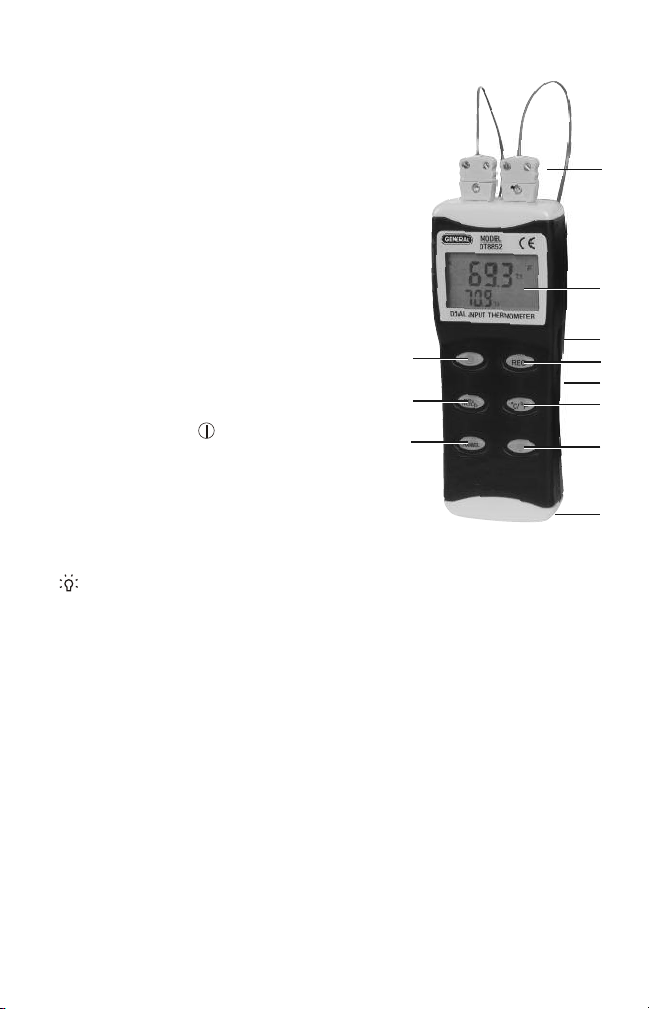
PRODUCT OVERVIEW
Figure 1 on p. 4 shows all of the controls, indicators and physical
features of the DT8852 and DT8856. The descriptions of Callouts A
and I detail the two differences between those dual-input models and
the single-input DT8855. Figure 2 on p. 5 shows all possible
indications on the LCD. Familiarize yourself with the positions and
functions of all controls, indicators and physical features before
moving on to the Setup Instructions and Operating Instructions.
A. Two spade-lug thermocouple probes plugged into T1 (left) and T2
(right) jacks (DT8852 and DT8856 only; DT8855 has only one (T1)
jack on left)
B. LCD
C.
RS232
jack (on side)
REC
D.
button:
•
Pressed briefly with unit in real-time mode
Record mode.
, begins operation in
3
Page 4
•
Pressed once briefly in Record mode
, switches primary
temperature display to show maximum temperature recorded
since entering Record mode.
Pressed twice briefly in Record
•
mode
,
switches primary display to
Fig. 1
show minimum temperature recorded
since entering Record mode.
•
Pressed a third time briefly in Record
mode
, resumes showing real-time
temperature sensed by T1 input on
primary display without exiting
Record mode.
Pressed and held with unit in Record
•
, exits operation in Record mode
mode
K
and resumes operation in real-time
mode.
• Also used with ,
REC
and
buttons to select thermocouple type.
DC9V
°C/°F
jack (on side)
button:
E.
F.
°C/°F
J
I
• Toggles between Celsius and Fahrenheit temperature units.
• Also used to select thermocouple type.
G. button. Pressed briefly, turns LCD backlight on for 30 seconds.
H. Battery compartment cover (opens from back)
CHANNEL
I.
• Pressing
button (DT8852 and DT8856):
CHANNEL
button once switches primary display to show
value of T2 input and secondary display to show value of T1 input.
•
Pressing button again
switches primary display to show
difference between T1 and T2 inputs (T1-T2) and causes
secondary display to toggle between T1 and T2 readings.
•
Pressing button again
resumes normal display (T1 on primary
display and T2 on secondary display).
TIMER
button (DT8855). Pressed briefly, starts relative time clock for
use as measurement reference.
REL/HOLD
J.
•
Pressed briefly
button:
, “freezes” primary temperature readout with T1
reading while allowing secondary readout to continue updating
with real-time T2 value.
4
A
B
C
D
E
F
G
H
Page 5

•
12 34
Pressed and held
baseline of subsequent T1 readings until
, makes T1 input value at that moment the
REL/HOLD
button is
pressed again.
• Also used with button to disable Auto Power Off function.
K. button:
Pressed briefly
•
, powers thermometer on and off.
• With thermometer off, pressing button briefly at same time as
REL/HOLD
button powers unit on and disables 20-minute Auto
Power Off function.
• With thermometer off, pressing button at same time as
button enables selection of thermocouple type.
Fig. 2. All possible display indications
1.
REC
. Indicates operation in
Record mode
MAX
and
MIN
2.
. Indicates that
primary temperature readout
is showing maximum or
minimum temperature sensed
since entering Record mode
HOLD
and
3.
REL. HOLD
7
8
9
indicates that primary display
is “frozen” at selected past
value of T1 input.
REL
indicates that reading on primary display represents difference
between value of real-time T1 input and value of T1 input when
REL
button was pressed.
BAT
. Indicates that battery is low on charge and should be replaced
4.
°C and °F
5.
T1-T2
6.
between values of T1 and T2 inputs.
. Indicates selected temperature unit
. Indicates that primary display is showing difference
T1
and T2at right of
secondary display indicate which value is shown on secondary
display.
7. Primary temperature readout
K, J, T, R, S, E
8.
. Indicates selected thermocouple type
9. Secondary temperature readout
10. Relative clock readout
REC
10
5
6
6
5
Page 6

SETUP INSTRUCTIONS
SELECT THERMOCOUPLE TYPE
Before plugging any thermocouples into the jacks on the top of the
thermometer, you must ensure that the instrument is configured for
the type of thermocouple to be used. DT8852 and DT8856 users: You
cannot plug two different types of thermocouple into the jacks. You
must use two probes of the same type.
By default, the DT8852/8855/8856 has been configured to work with
“K” type thermocouples. If you plan to use only “K” type thermocouples,
skip ahead to the “Install Thermocouple(s)” section below.
If you plan to use type “J”, “T”, “R”, “S” or “E”.thermocouples, use the
following procedure to configure the thermometer for the selected
type.
REC
1) With the thermometer powered off, press and hold the
while pressing the button. The letter “K” will appear on the left
side of the LCD.
°C/°F
2) Press the
button as many times as necessary to change “K”
to the letter of the thermocouple type that you plan to use. For the
DT8852, the “other” options are “J” and “T”. For the DT8855 and
DT8856, the “other” options are “J”, “T”, “R”, “S” and “E”.
3) Press the
REC
button to save your selection. A large letter “S” will
appear in the center of the LCD for a few seconds. The thermometer
will then power on, with the letter corresponding to your selected
thermocouple type on the left side of the LCD and one set (DT8855)
or two sets (DT8852 and DT8856) of four dashes on the primary
and secondary readouts.
INSTALL THERMOCOUPLE(S)
Using the photo on the right as
BACK OF INSTRUMENT
a guide, plug one (DT8855) or
two (DT8852 or DT8856)
T1
thermocouples of the selected
type into the T1 jack (DT8855) or
T1 and T2 jacks (DT8852 and
DT8856) on the top of the
thermometer. On spade-lug
FRONT OF INSTRUMENT
thermocouple probes, the narrower lug is the positive (+) terminal and
the wider lug is the negative (-) terminal.
6
button
T2
Page 7

DT8852 and DT8856 users: If you insert only one thermocouple into
the T1 or T2 port, the readout corresponding to the unused port will
show four dashes (see figure below).
OPERATING INSTRUCTIONS
MONITORING TEMPERATURE(S) IN REAL TIME
To measure temperatures sensed by installed thermocouples
the button to power on the unit. The T1 temperature will appear on
the primary readout (all three models). The T2 temperature (DT8852
and DT8856 only) will appear on the secondary readout. This is the
“normal” display mode.
To swap the readouts
T2 is shown on the primary readout), press the
(DT8852 and DT8856 only). This is the “swap” display mode.
To show T1-T2 on the primary readout
T1 and T2 on the secondary readout, press the
(DT8852 and DT8856 only). This is the “T1-T2” display mode.
To resume showing T1 on the primary readout and T2 on the
secondary readout, press the
DT8856 only).
When the thermometer is powered on, it will resume operation in the
same Channel mode—normal, swap, or T1-T2—that it was in when it
was powered off.
To hold a T1 reading
REL/HOLD
continue to be updated on the secondary readout (DT8852 and
DT8856 only). To release the hold and resume showing real-time
T1 values on the primary readout, briefly press the
again.
On the single-input DT8855, the button at the lower left of the front
panel is labeled
button starts a running clock with 1-second resolution in the lower
button. While the T1 reading is held, the T2 reading will
(so T1 is shown on the secondary readout and
CHANNEL
and alternating temperatures
CHANNEL
CHANNEL
(“freeze” the primary readout), briefly press the
TIMER
, rather than
button again (DT8852 and
REL/HOLD
CHANNEL
. Pressing the
, press
button once
button again
button
TIMER
7
Page 8

right corner of the LCD. This clock can serve as a relative time
reference for temperature measurements.
MAKING RELATIVE MEASUREMENTS
To track changes in T1 temperature over time relative to a T1
temperature at a particular time, press and hold the
REL/HOLD
button
at that time. In Rel mode, the primary readout will show the difference
between the real-time temperature sensed by the T1 thermocouple
and the T1 temperature when Rel mode was entered.
For example, if the value of T1 is 25°C when Rel mode is entered and
the temperature later rises to 30°C, the primary readout will show
5°C (30 – 25), accompanied by the term
REL
on the top line of the
LCD. If the temperature then falls to 20°C, the primary readout will
show -5°C (20 – 25).
In Rel mode, the secondary readout will continue to show the real-time
temperature sensed by the T2 thermocouple (DT8852 and DT8856 only).
To exit Rel mode and resume showing T1 on the primary readout and T2
on the secondary readout, press and hold the
To select a temperature unit (Fahrenheit or Celsius), use the
REL/HOLD
button again.
°C/°F
button. The selected unit will appear at the right of the primary
readout.
To turn on the display backlight for 30 seconds, press the button.
RECORDING MIN/MAX TEMPERATURES
In Record mode, the DT8852, DT8855 and DT8856 continuously track
the maximum and minimum temperatures (Max and Min) sensed
through the T1 port. The instrument also notes the time at which each
temperature occurred. The two times are not referenced to an absolute
clock (as in a conventional time stamp), but rather to the time at which
Record mode was entered. The recorded times at which Max and Min
occurred can be considered relative time stamps.
To enter Record mode
, briefly press the
REC
button. The values on the
primary and secondary readouts will not change, and will continue to
track the T1 (all three models) and T2 (DT8852 and DT8856 only)
temperatures. However, pressing the
REC
to appear in the upper left corner of the LCD and 2) starts a
REC
button 1) causes the term
running clock with 1-second resolution in the lower right corner of the
LCD. In Record mode, all front-panel buttons except the and
buttons are disabled.
8
Page 9

Once Record mode has been entered, one brief press of the
REC
button switches the primary readout to show the highest temperature
MAX
recorded since entering Record mode, along with the term
above
it. The relative time at which this maximum temperature occurred is
indicated by the time shown in the lower right corner. The secondary
readout will continue to show the real-time temperature sensed by the
T2 thermocouple (DT8852 and DT8856 only).
A second brief press of the
REC
button switches the primary readout
to show the lowest temperature recorded since entering Record mode,
along with the term
MIN
above it. The relative time at which this
minimum temperature occurred is indicated by the time shown in the
lower right corner. As before, the secondary readout will continue to
show the real-time temperature sensed by the T2 thermocouple
(DT8852 and DT8856 only).
A third press of the
REC
button releases the primary readout to resume
showing the real-time T1 temperature, with the secondary readout
continuing to show T2 (DT8852 and DT8856 only). The relative time
clock will continue to run and indicate how long it has been since
Record mode was entered.
To exit Record mode, stop the relative clock, and resume “normal”
display mode—with T1 shown on the primary readout and T2 on the
secondary readout (DT8852 and DT8856 only)—press and hold the
REC
button for at least 3 seconds.
PC-ASSISTED DATA LOGGING
Although the DT8852, DT8855 and DT8856 lack internal memory, they
can be used as data logging instruments (in order to make multiple
temperature measurements over time at a user-specified sampling
rate) by connecting them to a PC via an optional hardware/software
package. The package, designated ASFTKIT, comprises an RS-232 to
USB converter/cable and a mini-disc containing PC interface/data
logging software.
ASFTKIT includes a user’s manual with instructions for connecting
the DT8852, DT8855 and DT8856 to a PC through the instrument’s
RS-232 port (Fig. 1, Callout C). The manual also includes complete
instructions for setting data logging parameters such as sampling
time. Although the software was written before the debut of
Windows7, it works well with that operating system and its recent
predecessors. The only change that you may have to make to use the
9
Page 10

data logging package is to renumber the COM ports that represent
your PC’s USB jacks; the application can only stream data to COM
ports assigned a number between 1 and 4.
To enable long-term data logging, you must disable the thermometer’s
Auto Power Off (APO) feature. If you do not, the instrument will
automatically power off after 20 minutes of front-panel inactivity.
disable APO
the following special way: Press and hold the
, power the thermometer off and then power it back on in
REL/HOLD
button before
To
pressing the button. Doing so will cause a large, lower-case “n” to
appear on the LCD. Two seconds later, the “n” will disappear and the
instrument will power on normally—but with the APO function
disabled. There is no display indication of APO status (whether the
function is enabled or disabled).
SPECIFICATIONS
Maximum Measurement Ranges
-328° to 2498°F (-200° to 1370°C) with “K” type thermocouple(s)
-328° to 1400°F (-200° to 760°C) with “J” type thermocouple(s)
-328° to 734°F (-200° to 390°C) with “T” type thermocouple(s)
32° to 1832°F (0° to 1000°C) with “R” type thermocouple(s)
32° to 3200°F (0° to 1760°C) with “S” type thermocouple(s)
-328° to 1357°F (-200° to 736°C) with “E” type thermocouple(s)
Measurement Accuracies (from 64° to 82°F)
±(0.1% of reading + 1.4°F (0.7°C)) with “K”, “J”, “T” and “E” type
thermocouple(s)
±(0.3% of reading + 1.4°F (0.7°C)) with “R” and “S” type
thermocouple(s)
Measurement Resolution
0.1° (F or C) below 1000°; 1° (F or C) above 1000°
Measurement Range of Included Thermocouple(s)
-58° to 392°F (-50° to 200°C)
Auto Power Off Trigger 20 minutes of front-panel inactivity
Operating Temperature 32° to 122°F (0° to 50°C) @<85% RH
Dimensions 7.16 x 2.83 x 1.18 in. (182 x 72 x 30mm)
Weight 7.8 oz. (220g)
Power Source One “9V” battery (included)
10
Page 11

OPERATING & MAINTENANCE TIPS
When
BAT
appears at the upper right of the LCD, it’s time to replace
the “9V” battery that powers the thermometer (although
measurements will remain valid for several hours after the icon first
appears).
After subjecting the thermometer to a large change in ambient
temperature, wait at least 30 minutes before making measurements to
guarantee the accuracy of readings.
Remove the battery when storing the unit or when you do not expect
to use it for an extended period of time (months rather than weeks).
Do not disassemble the thermometer or immerse it in water. Doing so
voids the 1-year limited warranty.
WARRANTY INFORMATION
General Tools & Instruments’ (General’s) DT8852, DT8855 or DT8856
Digital Thermocouple Thermometer is warranted to the original
purchaser to be free from defects in material and workmanship for a
period of one year. Subject to certain restrictions, General will repair or
replace this instrument if, after examination, the company determines
it to be defective in material or workmanship. The warranty period
begins on the date of purchase. You are encouraged to register your
product online. General will extend your warranty an additional
60 days if you register at www.generaltools.com/Product Registry.
This warranty does not apply to damages that General determines to
be from an attempted repair by nonauthorized personnel or misuse,
alterations, normal wear and tear, or accidental damage. The defective
unit must be returned to General Tools & Instruments or to a Generalauthorized service center, freight prepaid and insured.
Acceptance of the exclusive repair and replacement remedies
described herein is a condition of the contract for purchase of this
product. In no event shall General be liable for any incidental, special,
consequential or punitive damages, or for any cost, attorneys’ fees,
expenses, or losses alleged to be a consequence of damage due to
failure of, or defect in any product including, but not limited to, any
claims for loss of profits.
11
Page 12

RETURN FOR REPAIR POLICY
Every effort has been made to provide you with a reliable product of
superior quality. However, in the event your instrument requires repair,
please contact our Customer Service to obtain an RGA (Return Goods
Authorization) number before forwarding the unit via prepaid freight to
the attention of our Service Center at this address:
Remember to include a copy of your proof of purchase, your return
address, and your phone number and/or e-mail address.
12
Page 13

99 Washington Street
Melrose, MA 02176
Phone 781-665-1400
Toll Free 1-800-517-8431
Visit us at www.TestEquipmentDepot.com
Specifications subject to change without notice
NOTICE - WE ARE NOT RESPONSIBLE FOR TYPOGRAPHICAL ERRORS.
©2013 GENERAL TOOLS & INSTRUMENTS
MAN# DT8852, DT8855, DT8856-condensed
7/31/13
 Loading...