

Page 1
HIGH-PERFORMANCE VIDEO
BORESCOPE SYSTEM
WITH 4.9mm SWITCHABLE
FRONT/SIDE VIEW
FLEXIBLE-OBEDIENT PROBE
USER’S MANUAL
DCS1100
99 Washington Street
Melrose, MA 02176
Phone 781-665-1400
Toll Free 1-800-517-8431
Visit us at www.TestEquipmentDepot.com
Please read this manual carefully and thoroughly before using this product.
Page 2

TABLE OF CONTENTS
Introduction . . . . . . . . . . . . . . . . . . . . . . . . . . . . . . . 3
Key Features. . . . . . . . . . . . . . . . . . . . . . . . . . . . . . . 4
Safety Instructions. . . . . . . . . . . . . . . . . . . . . . . . . . 4
What’s in the Case . . . . . . . . . . . . . . . . . . . . . . . . . . 4
Product Overview. . . . . . . . . . . . . . . . . . . . . . . . 5 –6
Setup Instructions . . . . . . . . . . . . . . . . . . . . . . . 6 –7
Install Four Batteries . . . . . . . . . . . . . . . . . . . . . 6
Attaching an Optional . . . . . . . . . . . . . . . . . . . . 7
High-Performance Probe
Operating Instructions . . . . . . . . . . . . . . . . . . . . 7 –8
Power On the System. . . . . . . . . . . . . . . . . . . . . 7
Normal Operation. . . . . . . . . . . . . . . . . . . . . 7 –8
Specifications. . . . . . . . . . . . . . . . . . . . . . . . . . . . . . 9
Maintenance Tips. . . . . . . . . . . . . . . . . . . . . . . . . . 10
Optional Accessories . . . . . . . . . . . . . . . . . . . . . . . 10
Warranty Information. . . . . . . . . . . . . . . . . . . . . . . 11
Return for Repair Policy. . . . . . . . . . . . . . . . . . . . . 11
2
Page 3

INTRODUCTION
Thank you for purchasing General Tools & Instruments’ DCS1100 HighPerformance Video Borescope System with 4.9mm Diameter Switchable
Front/Side View Flexible-Obedient Probe. Please read this user’s manual
carefully and thoroughly before using the system.
The standard DCS1100 system consists of a handheld display unit/controller
(the handle) connected to General’s P1618FS-49 Switchable Front/Side View
Probe (the probe). The handle also can be connected to any high-performance
probe for General’s DCS1600 High-Performance, Recording Borescope System.
Among them are:
• Slim (5.5mm diameter) soft metal and flexible-obedient probes
of various lengths up to 30m (98 ft.)
• 6mm diameter articulating probes of two different lengths
(1m and 2m)
• An ultra-slim (3.9mm) flexible-obedient probe that is thin enough to
fit inside the spark plug hole of a gasoline engine or the glow plug
hole of a diesel engine
All of the above probes have superior optical performance specifications,
including a depth of field of 10 to 60mm (0.4 to 2.4 in.) and a minimal focal
length of 38mm (1.5 in.) for very close-up viewing of areas of interest. See the
Optional Accessories section of this manual for part numbers, and then visit
http://www.generaltools.com or call 212-431-6100 to order.
Ideally suited for aircraft/automotive inspection, maintenance and repair or for
government/security/military tasks, the DCS1100 system also can handle a
wide variety of less-demanding industrial tasks—such as inspecting buildings
for mold, leaks or pests; inspecting ducts and pipelines for corrosion or leaks;
and reading parts and serial numbers of equipment. The DCS1100 offers a
cost-effective way for technicians, mechanics, contractors and repairmen to
visually inspect inaccessible or hazardous areas and thus diagnose hidden
system problems without the need for a complete disassembly or teardown.
3
Page 4

KEY FEATURES
• Super-slim 4.9mm (0.193 in.) diameter x 1m long high-performance
P1618FS-49 switchable front/side view probe with two separate
cameras and light sources
• 2.4-inch (diagonal) thin-film transistor (TFT) LCD with a resolution of
320 x 240 pixels
• Separate controls for brightness up and down, and 1.5X
zooming/mirroring of video
• Video Out jack for connecting to a computer monitor or TV
• Powered by four “AA” batteries
SAFETY INSTRUCTIONS
Although the high-performance probes that attach to the DCS1100 are water,
dust and oil-proof, never insert them into any flammable gas or liquid (including
fuels in an oil, gasoline or diesel tank). Also remember that the probes are not
electrically insulated, so never bring them into contact with exposed AC wiring.
The DCS1100 is intended for industrial use only. Do not use it for human or any
other biological inspections.
WHAT’S IN THE CASE
The DCS1100 system comes fully assembled in a custom hard carrying case
along with a 6 ft. video cable and this user’s manual.
4
Page 5

PRODUCT OVERVIEW
Figure 1 shows the key components of the DCS1100 handle, shown attached to
a generic camera probe.
(POWER) button
2.4 in. (diagonal) LCD
Brightness Up button
Power on light
Brightness Down button
Zoom/Mirror button
Hanger hole
High-performance probe
Probe’s camera head
Socket for high-
performance probe
AV out jack
TOP
FRONT
1. The DCS1100 handle’s controls, indicators and other physical features
5
Page 6

Figure 2 shows the key components
of the P1618FS-49 probe.
FRONT
VIEW
SIDE
VIEW
To probe socket on
DCS1100 handle
View indicator lights
View switch
2. The P1618FS-49’s
controls, indicators and
other physical features
SETUP INSTRUCTIONS
INSTALL 4 BATTERIES
To open the battery compartment (on
the back of the handle), lift up the semicircular metal ring on the screw in the
recess at the bottom of the plastic
compartment cover. Using the ring as a
crank, turn the screw counterclockwise until the cover loosens. Pulling on the
ring, pop the battery compartment open to expose the batteries.
Install four new “AA” batteries, using the
+ and – marks inside the battery
compartment as a guide. Close the
battery compartment cover and secure
it by using the ring to turn the screw
clockwise. Finally, push the ring over so
it is flush with the top of the screw in the recess.
6
Page 7
ATTACHING AN OPTIONAL HIGH-PERFORMANCE PROBE
To replace the included front/side view probe with another compatible highperformance probe from General, first detach the front/side view probe from
the handle by turning its collar counterclockwise and pulling the probe straight
out and away.
To attach the new probe, plug its connector into the handle’s probe socket. The
probe and the handle mate in only one way: when the red dot under the collar
on the end of the probe is aligned with the flat on the probe socket. After
orienting the new probe, push its connector into the socket and tighten the
collar by turning it clockwise.
Whether you use the included probe or an optional probe, remember to remove
the protective rubber cap from its camera end before using it.
OPERATING INSTRUCTIONS
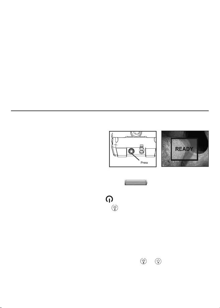
POWER ON THE SYSTEM
To power on the DCS1100, press the
black rubber button with the icon on
the top of the grip and hold it for five
seconds. A green light at the bottom of
the button will illuminate. The word
“READY” will appear inside a box in the middle of the display.
At the upper right of the display a green icon indicating the level of
battery charge will appear.
(To power off the DCS1100, press the button and hold it for five seconds
until the green light at the bottom of the button extinguishes.)
NORMAL OPERATION
To use the DCS1100, point the camera end of the probe at the area or object of
interest. Live video will appear on the display.
To change the view of the front/side view probe, toggle the view switch
(see Figure 2).
To change the brightness of the display, press the or button repeatedly
until the screen is at the optimum brightness for your environment. Each click
of the buttons increases or decreases the brightness by one step. Maximum
brightness is indicated by a “15” at the bottom of the screen. Minimum
brightness is indicated by a “0”.
7
Page 8

To magnify (zoom in on) the display by a factor of 50% (1.5X zoom), press
the button. The display will show a magnified version of the live video seen
by the probe, and the word “ZOOM” will appear on the bottom of the display for
five seconds.
To zoom out to the default size,
press the button again. The
display will revert to its previous
size and the word “NORMAL” will
appear on the bottom of the
display for five seconds.
The button has a second function: mirroring the live video feed. The ability
to mirror video is useful only when it is necessary to read text (such as a serial
number) using an optional high-performance probe outfitted with a mirrored
viewing tip. The effect of the double mirroring is to make the text readable,
as shown below.
To mirror the video feed, press the button, hold it for three seconds, and
then release the button. The live video feed will then switch to a mirror image
of itself with the letter “M” at the top right of the screen. The mirroring and
the “M” will remain until the next time the button is pressed and held for
three seconds.
To view the video from the camera probe on a larger display, such as a
television or computer monitor, plug the mini-stereo plug at one end of the
supplied video cable into the AV out jack (labeled “TV”) on the top of the
DCS1100. Plug either the yellow or white RCA plug at the other end of the cable
into the “Video In” jack of your TV or monitor. The video will appear both on the
TV or computer monitor and on the DCS1100’s display. The only difference
between the two displays is that video sent to an external monitor cannot be
zoomed or mirrored.
8
Page 9

SPECIFICATIONS
Handle Display Type Thin-film transistor (TFT) liquid crystal
Size 2.4 in. (61mm) diagonal
Resolution 320 x 240 pixels
Estimated battery life 8 hours
Operating temperature 32° to 140°F (0° to 60°C)
Storage temperature 32° to 140°F (0° to 60°C)
Dimensions 3.68 x 8.25 x 2.26 in. (93.5 x 209.5 x 57.5mm)
Weight (w/battery) 12.6 oz. (357g)
Power source 4 “AA” batteries
Probe Diameter 4.9mm (0.19 in.)
Length 1m (39.37 in.)
Operating temperature 32° to 131°F (0° to 55°C)
Water resistance To IP57 standards
Head material Stainless steel
Head length 36mm (1.42 in.)
Depth of field Horizontal field angle: 45.2°
Vertical field angle: 34°
Diagonal field angle: 56°
Light source 3 LEDs, each w/luminous intensity of
140 to 224 mcd (millicandelas)
Weight 5.1 oz. (145g)
9
Page 10

MAINTENANCE TIPS
The Switchable Front/Side View Probe contains thin wires running along its
entire length. Accordingly, handle it with care.
• Do not bend it more than 90° anywhere along its length.
• Do not bend the probe more than 70° within 30mm (1.2 in.) of its
camera tip.
• Do not bundle the probe into a tight circle to store it.
• Never use the camera end to clear its own path of debris.
• Do not overtighten the collar that secures the probe to the handle.
The DCS1100 handle requires no routine maintenance other than periodic
cleaning. To clean it, use a soft dry cloth. Never use a wet cloth, solvents or
water.
If your video display has spots, gently clean the camera head with a soft,
dry cloth.
Avoid leaving the handle in direct sunlight for long periods of time.
Whenever the DCS1100 will not be used for long periods of time, remove the
batteries and store the instrument in a cool, dry and well-ventilated place.
OPTIONAL ACCESSORIES
High-performance probes compatible with the DCS1100
Description General Part No.
5.5mm (0.22 in.) x 1m (3.28 ft.) long Flexible-Obedient Probe P16181SR-M
5.5mm (0.22 in.) x 2m (6.6 ft.) long Flexible-Obedient Probe P16182SR-M
5.5mm (0.22 in.) x 3m (9.8 ft.) long Flexible-Obedient Probe P16183SR-M
5.5mm (0.22 in.) x 1m (3.28 ft.) long Soft Metal Probe P16181SM-M
5.5mm (0.22 in.) x 3m (9.8 ft.) long Soft Metal Probe P16183SM-M
5.5mm (0.22 in.) x 5m (16 ft.) long Soft Metal Probe P16185SM-M
5.5mm (0.22 in.) x 10m (32 ft.) long Soft Metal Probe P161810SM-M
5.5mm (0.22 in.) x 30m (98 ft.) long Soft Metal Probe P161830SM-M
6.0mm (0.23 in.) x 1m (3.28 ft.) long Soft Metal Articulating Probe P16ART-1SM
6.0mm (0.23 in.) x 2m (6.6 ft.) long Soft Metal Articulating Probe P16ART-2SM
3.9mm (0.15 in.) x 0.75m (29.5 in.) long Flexible-Obedient Probe P1839-M
10
Page 11

WARRANTY INFORMATION
General Tools & Instruments’ (General’s) DCS1100 High-Performance Video
Borescope System is warranted to the original purchaser to be free from
defects in material and workmanship for a period of one year. Subject to certain
restrictions, General will repair or replace this instrument if, after examination,
the company determines it to be defective in material or workmanship.
This warranty does not apply to damages that General determines to be from
an attempted repair by non-authorized personnel or misuse, alterations, normal
wear and tear, or accidental damage. The defective unit must be returned to
General Tools & Instruments or to a General-authorized service center, freight
prepaid and insured.
Acceptance of the exclusive repair and replacement remedies described herein
is a condition of the contract for purchase of this product. In no event shall
General be liable for any incidental, special, consequential or punitive damages,
or for any cost, attorneys’ fees, expenses, or losses alleged to be a
consequence of any damage due to failure of, or defect in any product
including, but not limited to, any claims for loss of profits.
RETURN FOR REPAIR POLICY
Every effort has been made to provide you with a reliable product of superior
quality. However, in the event your instrument requires repair, please contact
our Customer Service to obtain an RGA (Return Goods Authorization) number
before forwarding the unit via prepaid freight to the attention of our Service
Center at this address:
Remember to include a copy of your proof of purchase, your return address,
and your phone number and/or e-mail address.
11
Page 12

99 Washington Street
Melrose, MA 02176
Phone 781-665-1400
Toll Free 1-800-517-8431
Visit us at www.TestEquipmentDepot.com
Specifications subject to change without notice
NOTICE - WE ARE NOT RESPONSIBLE FOR TYPOGRAPHICAL ERRORS.
©2011 GENERAL TOOLS & INSTRUMENTS
MAN#DCS1100 7/13/11
 Loading...