

Page 1
AUTO RANGING
600A AC
CLAMP METER/
AUTO RANGING
AC/DC TRUE
RMS 400A
CLAMP METER
USER’S MANUAL
DAMP60/DAMP68
Please read this manual carefully and thoroughly before using this product.
DAMP60_68_MANUAL_FINAL_F-111511_awb 11/15/11 3:24 PM Page 1
Page 2
INTRODUCTION
Thank you for purchasing General Tools &
Instruments’ (General’s) DAMP60 or DAMP68
Auto Ranging Clamp Meter. Please read this
user’s manual carefully and thoroughly before
using the instrument.
Each meter combines the functions of a voltmeter
and a clamp-type ammeter. Both are designed for
use in an industrial setting.
The DAMP60 is designed to be used by HVAC/R
contractors, building maintenance technicians
and electricians.
The DAMP68—with more features (see table
below)—is designed for precise measurement
and analysis of AC/DC power circuits by
process/power plant operators, HVAC/R
contractors and electrical technicians.
The DAMP60 and DAMP68 are easy to use,
ruggedly built and designed for safety. Both
instruments are ETL certified for CAT III 600V use.
3
TABLE OF CONTENTS
Introduction . . . . . . . . . . . . . . . . . . . . . . . . . 3
Key Features . . . . . . . . . . . . . . . . . . . . . 4 –5
What's in the Blister Pack . . . . . . . . . . . . . 5
Product Overview . . . . . . . . . . . . . . . . . 5 –7
Safety Instructions . . . . . . . . . . . . . . . 8 – 11
Setup Instructions . . . . . . . . . . . . . . . . . . . 11
Install Batteries . . . . . . . . . . . . . . . . . . . 11
Operating Instructions . . . . . . . . . . . 11 – 17
Measuring AC or DC Current . . . . . 11 – 12
Measuring DC Voltage . . . . . . . . . . . . . . 13
Measuring AC Voltage . . . . . . . . . . . . . . 14
Measuring Resistance . . . . . . . . . . 14 – 15
Checking the Integrity of a Diode
. . 15 – 16
Checking for Continuity . . . . . . . . . . . . . 16
Measuring Temperature
(DAMP68 only) . . . . . . . . . . . . . . . . . . . . 16
Measuring Capacitance
(DAMP68 only) . . . . . . . . . . . . . . . . . . . . 17
Measuring Frequency . . . . . . . . . . . . . . 17
Powering Off . . . . . . . . . . . . . . . . . . . . . . 17
Specifications . . . . . . . . . . . . . . . . . . 18 – 21
Warranty Information . . . . . . . . . . . . . . . . 22
Return for Repair Policy . . . . . . . . . . . . . . 23
Manuel de L’Utilisateur . . . . . . . . . . . 25 – 47
2
KEY FEATURES & SPECS COMPARISON
Feature or Specification DAMP68 DAMP60
Parameters Measured AC/DC voltage, AC/DC voltage, AC current,
AC/DC current, resistance, resistance, frequency
frequency, capacitance,
temperature
AC Current Range 0 to 400A 0 to 600A
DC Current Range 0 to 400A N/A
True RMS Voltage & Yes No
Current Readings
Resistance Range 0 to 40MΩ 0 to 20MΩ
Frequency Range 0 to 9.999MHz 10 to 1999Hz
Capacitance Range 0 to 4000F N/A
Temperature Range -40° to 752°F N/A
(-40° to 400°C)
Clamp Jaw Type Hall effect Coil-type
Opening 1.2 in. (31mm) 1.1 in. (28mm)
Display Maximum Count 4000 2000
Analog Bar Graph Yes No
Ranging Options Auto or manual Autoranging only
Zero Offset Yes No
Memory No Maximum value
Power Source Three “AAA” batteries Two “AAA” batteries
DAMP60_68_MANUAL_FINAL_F-111511_awb 11/15/11 3:24 PM Page 2
Page 3

• Auto ranging or manual ranging
• Ergonomic design with rugged rubber housing
• Data hold, zero offset buttons
• Hall effect clamp jaw
WHAT’S IN THE
BLISTER PACK
The DAMP60 and DAMP68 each come in a blister
pack along with a black soft pouch with a belt
loop.
The pouch for the DAMP60 contains a pair of red
and black test leads, (2) “AAA” batteries and this
user’s manual.
The pouch for the DAMP68 contains a pair of red
and black test leads, a “K” type thermocouple
probe, (3) “AAA” batteries and this user’s
manual.
PRODUCT OVERVIEW
Fig. 1 shows the labels and positions of the
controls and connectors on the front of the
DAMP60 and DAMP68. Fig. 2 shows all possible
display indications on both units. Familiarize
yourself with the functions and meanings of these
controls, indicators and connectors before
moving on to the Setup Instructions.
5
KEY FEATURES
DAMP60 AUTO RANGING 600A AC
CLAMP METER
• 7 functions, 20 ranges
• CAT III 600V ETL certified
• Measures AC and DC voltage, AC current,
resistance and frequency
• Handles up to 600A AC
• Verifies integrity of diodes and checks circuits
for continuity
• Jumbo 3-1/2 digit (2000 count) backlit LCD
• Ergonomic design with rugged rubber housing
• Max memory, data hold buttons
• Auto power off
• Coil-type clamp jaw
DAMP68 AUTO RANGING AC/DC
TRUE RMS 400A CLAMP METER
• 11 functions, 34 ranges
• CAT III 600V ETL certified
• Computes and displays True RMS values
• Measures AC/DC voltage, AC/DC current,
resistance, capacitance and frequency
• Handles up to 400A AC or DC
• Also measures temperature with included “K”
type thermocouple
• Verifies integrity of diodes and checks circuits
for continuity
• Jumbo 3-3/4 digit (4000 count) backlit LCD
+ analog bar graph
4
DAMP60_68_MANUAL_FINAL_F-111511_awb 11/15/11 3:24 PM Page 4
Page 4

3) °F or °C temperature unit (DAMP68 only);
4) AC or DC current measurement mode
(DAMP68 only)
7.
HOLD
button (DAMP60);
RANGE
button
(DAMP68). On DAMP60, pressing this button
briefly holds/releases displayed measurement.
On DAMP68, pressing this button briefly
switches the meter from auto ranging mode
(default) to manual ranging mode. To return to
auto ranging mode, press and hold the
RANGE
button for 2+ seconds.
8. Clamp jaw release
9. Test lead sockets
DAMP60
DAMP68
76
1. 3-1/2 digit LCD
(DAMP60); 3-3/4 digit
LCD + analog bar
graph (DAMP68)
2. Clamp jaw
3. Function switch
4. Backlight button
(DAMP60);
Backlight/
HOLD
button
(DAMP68). On both
models, pressing and
holding this button for
2+ seconds turns
display backlight on
for 10 seconds. On
DAMP68, pressing
this button briefly
holds/releases
displayed
measurement.
5.
MAX
button (DAMP60);
ZERO
button
(DAMP68). On DAMP60, pressing this button
displays maximum value of displayed
parameter over time. On DAMP68, pressing
this button “zeroes out” the display (subtracts
the offset) before measuring DC current. In
auto ranging mode, pressing the
ZERO
button again displays the offset value.
6.
SHIFT
button (DAMP60 and DAMP68).
Press to select:
1) resistance measurement, diode check or
continuity check mode (DAMP60);
2) resistance measurement, diode check,
continuity check or capacitance measurement
mode (DAMP68);
3
2
5
7
9
4
1
6
8
Fig. 1. The controls,
indicators and
connectors of the
DAMP60 and DAMP68
Fig. 2. All possible display indications on the
DAMP60 (top) and DAMP68 (bottom)
DAMP60_68_MANUAL_FINAL_F-111511_awb 11/15/11 3:24 PM Page 6
Page 5

• Use caution when working with voltages above
42V ACrms, or 60V DC. These voltages pose a
shock hazard.
• Use the proper terminals, function, and range
for all measurements.
•
WARNING
Do not operate the meter around
explosive gas, vapor, or dust.
•
WARNING
When using the probes, keep your
fingers behind the finger guards. Do not touch
the metal probes of the test leads when making
a measurement.
• When making connections, connect the
black (–) test lead before connecting the
red (+) test lead; when disconnecting,
disconnect the red (+) test lead before
disconnecting the black (–) test lead.
• Disconnect circuit power and discharge all
high-voltage capacitors before
measuring/testing resistance, continuity,
diodes, or capacitance.
• For all DC functions in both auto and manual
ranging mode, to avoid the risk of shock due to
possible improper reading verify the presence
of any AC voltages by first using the AC
function. Then select a DC voltage range equal
to or greater than the AC range.
• Before measuring current, turn off power to
the circuit before connecting the meter.
• Do not operate the meter with the case
(or part of the case) removed.
98
SAFETY INSTRUCTIONS
WARNINg
To avoid possible electric shock or personal
injury, and to avoid damaging the meter or the
equipment under test:
• Do not use the meter in any way not detailed in
this manual or the meter's safety features may
be compromised.
• Before using the meter, inspect the case.
Do not use the meter if it is damaged. Look for
cracks or missing plastic. Pay particular
attention to the insulation around the
connectors.
•
WARNING
Inspect the test leads for damaged
insulation or exposed metal. Check the test
leads for continuity. Replace damaged test
leads before using the meter.
• Verify the meter’s operation by measuring a
known voltage. Do not use the meter if it
operates abnormally. Protection may be
impaired. When in doubt, have the meter
serviced.
•
WARNING
Do not apply more than the rated
voltage, as marked on the meter, between the
terminals or between any terminal and ground.
•
WARNING
Do not measure voltages above
600V in Category III installations.
•
WARNING
Do not measure voltage when the
function switch points to the resistance (ohms),
current, capacitance or temperature settings.
Never measure current when the switch points
to the resistance (ohms), capacitance or
temperature settings.
DAMP60_68_MANUAL_FINAL_F-111511_awb 11/15/11 3:24 PM Page 8
Page 6
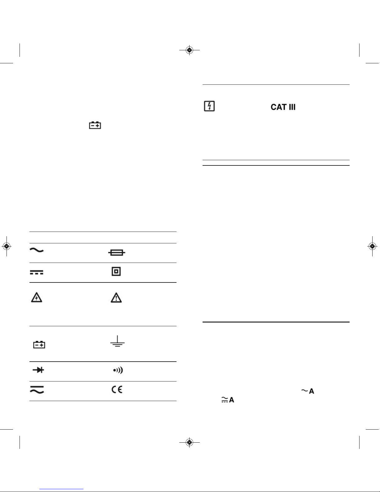
Symbol Description Symbol Description
Application and For measurements
removal from made on building
hazardous live equipment such
conductors as distribution
permitted panels, feeders
and short branch
circuits, and on
lighting systems in
large buildings.
SETUP INSTRUCTIONS
INSTALL BATTERIES
The battery compartment of the DAMP60 and
DAMP68 is located at the back of the meter.
To open the compartment, use a small Phillipshead screwdriver to remove the single screw
securing the battery compartment cover. Be
careful not to lose the small screw. Put the screw
and the cover to the side.
Install the supplied “AA” batteries (two in the
case of the DAMP60; three for the DAMP68) in
the battery compartment. Use the polarity marks
stenciled inside the compartment as a guide.
Replace the battery compartment cover and
secure it with the Phillips-head screw.
OPERATINg INSTRUCTIONS
MEASURING AC OR DC CURRENT
Warning
Before making current measurements, make
certain that all test leads are disconnected from
the meter terminals.
(1) Set the function switch to the (DAMP60)
or (DAMP68) position. For DAMP68,
AC current measurement is the default mode;
11
• Use only two “AAA” batteries (DAMP60), or
three “AAA” batteries (DAMP68), properly
installed in the battery compartment, to power
the meter. Do not use rechargeable batteries.
• Replace the batteries as soon as the low
battery indicator “ ” appears. Operated with
weak batteries, the meter might produce false
readings that could lead to electric shock and
personal injury.
• Remove the test leads from the meter before
opening the meter case or battery
compartment.
Electrical Symbols Used On the
Meter and In This Manual
Symbol Description Symbol Description
AC (Alternating Fuse
Current)
DC Double
(Direct Current) Insulated
Caution, risk of Risk of danger.
electric shock. Important
Hazardous information.
voltage. Refer to the
manual.
Battery
(Low battery) Earth ground
when shown
on display
Diode Continuity
Beeper
AC or DC Complies with
EU directives
10
DAMP60_68_MANUAL_FINAL_F-111511_awb 11/15/11 3:24 PM Page 10
Page 7

MEASURING DC VOLTAGE
Warning
Do not measure voltage higher than 600V. Doing
so may damage the meter’s internal circuitry. If
the voltage is over 1000 VDC, the beeper will
sound continuously, indicating an over-range
measurement.
(1) Set the function switch to the position.
(2) Plug the black and red test leads into the
– and + input terminals, respectively.
(3) Touch the black test lead to the lower-
potential point of the circuit under test, and
the red test lead to the higher-potential point.
(4) Read the measured voltage on the display. If
the test leads are reversed, a minus sign will
appear to the left of the displayed value.
13
press the
SHIFT
button to select DC current
measurement. Before measuring DC current,
press the
ZERO
button to clear (offset) the
last reading from the display.
(2) Squeezing the clamp jaw release to open the
jaw, place it around the conductor whose
current you wish to measure. Be sure to
enclose only one conductor (see figure below).
Enclosing both conductors of a pair will
produce a reading of
0
.
Note:
General’s ACL10 line splitter makes it possible
to safely attach the DAMP60 or DAMP68 to
a line cord carrying up to 15A AC without
separating its conductors, thereby damaging
the cord. For more information or to order, visit
www.generaltools.com and enter “ACL10” in
the SEARCH box.
(3) Read the measured value from the display. In
the case of the DAMP68, the displayed value
is a True RMS reading.
Notes:
Clamp the jaw around one
conductor only.
Close the jaw completely.
Center the wire in the jaw
for highest accuracy.
12
RED TEST LEAD
BLACK TEST LEAD
RED TEST LEAD
BLACK TEST LEAD
DAMP60_68_MANUAL_FINAL_F-111511_awb 11/15/11 3:24 PM Page 12
Page 8
(2) Plug the black and red test leads into the
– and + input terminals, respectively.
(3) Measure the resistance by touching the
probes to the desired test points of the circuit.
(4) Read the measured resistance on the display.
If the resistance value is over range,
OL
will
appear on the display.
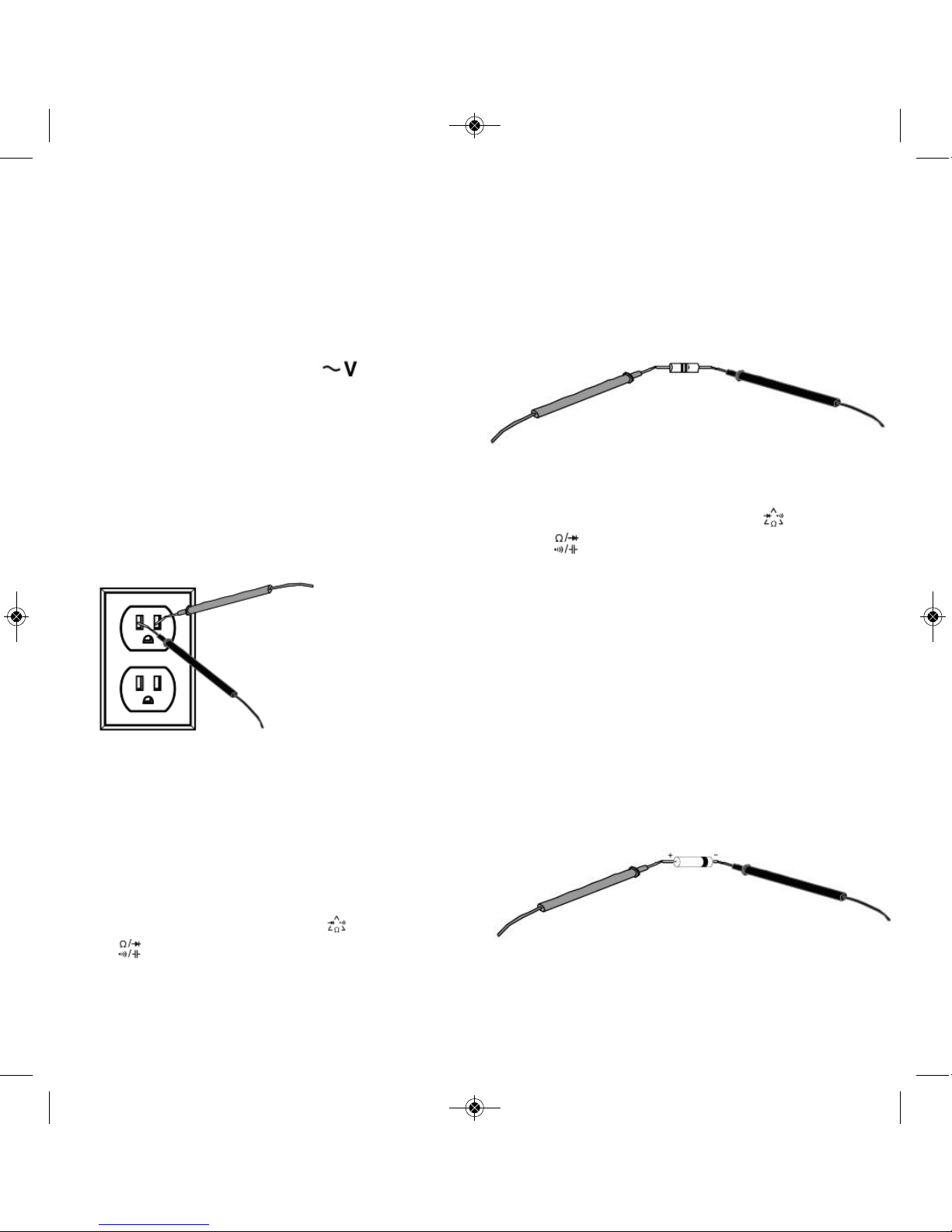
CHECKING THE INTEGRITY
OF A DIODE
(1) Turn the function switch to the (DAMP60)
or (DAMP68) position. Press the
SHIFT
button to select the diode check function.
(2) Plug the black and red test leads into the
– and + input terminals, respectively.
(3) Connect the red test lead to the anode
(positive terminal) of the diode to be tested,
and the black test lead to its cathode
(negative terminal).
(4) Read the forward bias voltage value on the
display.
(5) If the polarity of the test leads is reversed,
OL
will appear on the display. This can be used to
distinguish the anode and cathode of a diode.
(6) A silicon diode typically has a forward bias
voltage of 0.7V. A germanium diode typically
has a forward bias voltage of 0.3V. A
0V
reading in both directions indicates a shorted
15
MEASURING AC VOLTAGE
Warning
Do not measure voltages higher than 600V AC or
internal damage will occur. If the applied voltage
is over 750V AC, the beeper will sound
continuously, indicating an over-range
measurement.
(1) Set the function switch to the position.
(2) Plug the black and red test leads into the
– and + input terminals, respectively.
(3) Measure the voltage by touching the probes to
the desired points of the circuit. With AC
voltage, the polarity of the test leads is not a
factor.
(4) Read the measured voltage on the display.
MEASURING RESISTANCE
Warning
To avoid electrical shock or damage to the meter
when measuring resistance or continuity in a
circuit, make sure the power to the circuit is
turned off and all capacitors are discharged.
(1) Turn the function switch to the (DAMP60)
or (DAMP68) position. Make sure power is
disconnected from the circuit to be measured.
Resistance measurement is the default
function for this function switch position on
both the DAMP60 and DAMP68.
14
RED TEST LEAD
BLACK TEST LEAD
RED TEST LEAD
BLACK TEST LEAD
RED TEST LEAD
BLACK TEST LEAD
DAMP60_68_MANUAL_FINAL_F-111511_awb 11/15/11 3:24 PM Page 14
Page 9

MEASURING CAPACITANCE
(DAMP68 ONLY)
Warning
To avoid possible damage to the meter or other
equipment, turn off the power source and
discharge all high-voltage capacitors.
(1) Disconnect the capacitor from power.
(2) Short the capacitor’s terminals to discharge it.
(3) Disconnect any resistors between the
terminals of the capacitor.
(4) Set the rotary switch to the position.
Press the
SHIFT
button to select capacitance
measurement mode.
(5) Plug the black and red test leads into the
– and + input terminals, respectively.
(6) Connect the test leads to the terminals of the
capacitor.
(7) Read the measured capacitance value on the
display.
MEASURING FREQUENCY
(1) Turn the function switch to the
Hz
position.
(2) Plug the black and red test leads into the
– and + input terminals, respectively.
(3) Measure the frequency by touching the red
probe to any point of a circuit, and the black
probe to circuit ground.
(4) Read the measured frequency on the display.
POWERING OFF
When you have finished using the meter, rotate
the function switch to the
OFF
position.
The meter enters Sleep mode and the display
goes blank if no buttons are pushed and no input
is received for 15 minutes. Press any button to
wake the meter up.
17
diode. An OLreading indicates an open diode.
In either case, the diode is defective and
should be replaced.
CHECKING FOR CONTINUITY
(1) Turn the function switch to the (DAMP60)
or (DAMP68) position. Press the
SHIFT
button to select continuity checking mode.
(2) Plug the black and red test leads into the
– and + input terminals, respectively.
(3) Touch the test leads to any two points of a
circuit. If the resistance between those points
is ⭐30⍀, the beeper will sound continuously.
MEASURING TEMPERATURE
(DAMP68 ONLY)
Warning
To avoid possible damage to the meter or
other equipment, remember that the included
“K” Type thermocouple is rated -40° to 752°F
(-40° to 400°C).
When the meter is not connected to the included
thermocouple,
OL
will be shown on the display.
(1) Turn the function switch to the
°C/°F
position.
°C
is the default setting. Press the SHIFT
button to select
°F
.
(2) Plug the included “K” type thermocouple into
the meter's – and + terminals, making sure to
insert the pin marked + into the + terminal.
(3) Read the measured temperature on the
display.
16
DAMP60_68_MANUAL_FINAL_F-111511_awb 11/15/11 3:24 PM Page 16
Page 10

19
SPECIFICATIONS
Parameter or Specification DAMP60 DAMP68
Feature/Function
AC voltage Measurement ranges 0 to 1.999V/ 19.99V/ 0 to 400mV/ 4V/
199.9V/ 600V 40V/ 400V/ 600V
Measurement accuracy ±(1.0% + 5 digits) ±(1% + 5 digits);
±(2% + 10 digits)
for 400mV range only
DC voltage Measurement ranges 0 to 199.9mV/1.999V/ 0 to 400mV/ 4V/ 40V/
19.99V/199.9V/600V 400V/600V
Measurement accuracy ±(0.8% + 5 digits) ±(0.8% + 5 digits)
AC current Measurement range(s) 0 to 199.9A/600A 0 to 400A
Measurement accuracy ±(3% + 5 digits) ±(3% + 5 digits)
DC current Measurement range N/A 0 to 400A
Measurement accuracy N/A ±(3% + 5 digits)
Resistance Measurement ranges 0 to 199.9Ω/ 1.999kΩ/ 0 to 400Ω/4kΩ/40kΩ/
19.99kΩ/199.9kΩ/ 400kΩ/
1.999MΩ/19.99MΩ 4MΩ/40MΩ
Measurement accuracy ±(1% + 5 digits)@<1MΩ; ±(1% + 5 digits)@<1MΩ;
±(2% + 5 digits)@≥1MΩ ±(2% + 5 digits)@≥1MΩ
Frequency Measurement range(s) 10 to 1999Hz for 0 to 99.99Hz/999.9Hz/
inputs from 0.2V to 30Vrms
9.999kHz/99.99kHz/999.9kHz/
9.999MHz for inputs
from 2V to 600Vrms
Measurement accuracy ±(3% + 10 digits) ±2%
Capacitance Measurement ranges N/A 0 to 40nF/400nF/4
F/
40F/ 400F/4000F
Measurement accuracy N/A ±(4% + 5 digits)
Continuity Threshold ≤ 30Ω≤ 30Ω
Diode integrity Open circuit voltage 1.5V 2.7V
18
DAMP60_68_MANUAL_FINAL_F-111511_awb 11/15/11 3:24 PM Page 18
Page 11

2120
Parameter or Specification DAMP60 DAMP68
Feature/Function
Temperature Measurement range N/A -40° to 752°F (-40° to 400°C)
Measurement accuracy N/A
±(8% + 8 digits) from -40° to 4°F;
±(1.2% + 7 digits) from
4° to 32°F ; ±(1.2% + 6 digits)
from 32° to 212°F;
±(3% + 5 digits)@≥212°F
Dielectric strength 6000V AC 6000V AC
(Voltage that dielectric can
withstand for 1 minute)
ETL safety rating CAT III 600V
Clamp jaw Type Coil Hall effect
Opening 1.1 in. (28mm) 1.2 in. (31mm)
Display No. of digits 3-1/2 3-3/4
Maximum count 2000 4000
Analog bar graph No Yes
Backlight Yes Yes
Overload indication Yes Yes
Low battery indication Yes Yes
Ranging options Auto Auto or manual
Auto power off trigger 15 minutes 15 minutes
Data hold Yes Yes
True RMS measurement No Yes
Zero offset No Yes
Memory Maximum value No
Operating temperature 32° to 104°F (0° to 40°C) 32° to 104°F (0° to 40°C)
@<75% relative humidity @<75% relative humidity
Maximum altitude 6562 ft. (2000m) 6562 ft. (2000m)
Power source Two “AAA” batteries Three “AAA” batteries
Dimensions 11.25 x 6.13 x 2.75 in. 11.38 x 6.25 x 2.75 in.
(286 x 156 x 70mm) (289 x 159 x 70mm)
Weight 17 oz. (482g) 19 oz. (539g)
Note: All accuracy values stated at 73° F ± 4°F (23° ± 3°C) @<75% RH
DAMP60_68_MANUAL_FINAL_F-111511_awb 11/15/11 3:24 PM Page 20
Page 12

WARRANTY INFORMATION
General Tools & Instruments’ (General’s) DAMP60
and DAMP68 Auto Ranging Clamp Meters are
warranted to the original purchaser to be free
from defects in material and workmanship for a
period of one year. Subject to certain restrictions,
General will repair or replace this instrument
if, after examination, the company determines it
to be defective in material or workmanship.
This limited warranty does not apply to damages
that General determines to be from an attempted
repair by non-authorized personnel or misuse,
alterations, normal wear and tear, or accidental
damage. The defective unit must be returned to
General Tools & Instruments or to a Generalauthorized service center, freight prepaid and
insured.
Acceptance of the exclusive repair and
replacement remedies described herein is a
condition of the contract for purchase of this
product. In no event shall General be liable for
any incidental, special, consequential or punitive
damages, or for any cost, attorneys’ fees,
expenses, or losses alleged to be a consequence
of damage due to failure of, or defect in any
product including, but not limited to, any claims
for loss of profits.
2322
RETURN FOR REPAIR POLICY
Every effort has been made to provide you with a
reliable product of superior quality. However, in
the event your instrument requires repair, please
contact our Customer Service to obtain an
RGA (Return Goods Authorization) number before
forwarding the unit via prepaid freight to the
attention of our Service Center at this address:
General Tools & Instruments
80 White Street
New York, NY 10013
212-431-6100
Remember to include a copy of your proof of
purchase, your return address, and your phone
number and/or e-mail address.
DAMP60_68_MANUAL_FINAL_F-111511_awb 11/15/11 3:24 PM Page 22
Page 13

25
MULTIMÈTRE À PINCE
DE 600A CA À CALIBRAGE
AUTOMATIQUE/
MULTIMÈTRE
À PINCE EFFICACE VRAI DE
400 A CA/CC À CALIBRAGE
AUTOMATIQUE
MANUEL DE L’UTILISATEUR
DAMP60/DAMP68
Veuillez lire attentivement tout le manuel avant d’utiliser ce produit
NOTES
____________________________________
____________________________________
____________________________________
____________________________________
____________________________________
____________________________________
____________________________________
____________________________________
____________________________________
____________________________________
____________________________________
____________________________________
____________________________________
____________________________________
____________________________________
____________________________________
____________________________________
____________________________________
____________________________________
24
DAMP60_68_MANUAL_FINAL_F-111511_awb 11/15/11 3:24 PM Page 24
Page 14

INTRODUCTION
Merci d’avoir acheté un multimètre à pince à calibrage
automatique DAMP60 ou DAMP68 de General Tools &
Instruments (General). Veuillez lire attentivement tout
le manuel avant d’utiliser ce produit.
Chaque multimètre combine les fonctions de voltmètre
et d’ampèremètre à pince. Les deux sont conçus pour
le milieu industriel.
Le DAMP60 est conçu pour être utilisé par les
entrepreneurs en CVCA/R, les techniciens en
maintenance de bâtiments et les électriciens.
Le DAMP68 — avec plus de caractéristiques
(consulter le tableau ci-dessous) — est conçu pour
faire des analyses et des prises de mesure précises
des circuits d’alimentation CA/CC par des opérateurs
de centrales électriques et d’appareils de traitement,
des entrepreneurs en CVCA/R et des techniciens en
électricité.
Les appareils DAMP60 et DAMP68 sont faciles à
utiliser et construits pour être solides et sécuritaires.
Les deux appareils sont certifiés par l’ETL pour une
utilisation de CAT III 600 V.
27
TABLE DES MATIÈRES
Introduction . . . . . . . . . . . . . . . . . . . . . . . . . . . 27
Principales caractéristiques . . . . . . . . . . . . . . 28
Contenu de l’emballage . . . . . . . . . . . . . . . . . . 29
Aperçu du produit . . . . . . . . . . . . . . . . . . 29 – 31
Instructions de sécurité . . . . . . . . . . . . . 32 – 34
Instructions d’assemblage . . . . . . . . . . . . . . . 35
Installation des piles . . . . . . . . . . . . . . . . . . 35
Instructions de fonctionnement . . . . . . . 34 – 41
Mesure du courant CA ou CC . . . . . . . . 35 – 36
Mesure de la tension CC . . . . . . . . . . . . . . . . 37
Mesure de la tension CA . . . . . . . . . . . . . . . . 38
Mesure de la résistance . . . . . . . . . . . . 38 – 39
Vérification de l’intégrité d’une diode
. . 39 – 40
Test de continuité . . . . . . . . . . . . . . . . . . . . . 40
Mesure de la température
(DAMP68 seulement) . . . . . . . . . . . . . . . . . . 40
Mesure de la capacité
(DAMP68 seulement) . . . . . . . . . . . . . . . . . . 41
Mesure de la fréquence . . . . . . . . . . . . . . . . 41
Arrêt de l’appareil . . . . . . . . . . . . . . . . . . . . . 41
Caractéristiques techniques . . . . . . . . . . 42 – 45
Information sur la garantie . . . . . . . . . . . . . . . 46
Politique de retour pour réparation . . . . . . . . . 47
26
COMPARAISON DES PRINCIPALES CARACTÉRISTIQUES ET
DES CARACTÉRISTIQUES TECHNIQUES
Caractéristiques générales DAMP68 DAMP60
ou caractéristiques techniques
Paramètres mesurés Tension CA/CC, Tension CA/CC, courant CA,
courant CA/CC, résistance, résistance, fréquence
fréquence, capacité,
température
Étendue du courant CA De 0 à 400 A De 0 à 600 A
Étendue du courant CC De 0 à 400 A N/A
Vraie tension RMS Oui Non
et lectures du courant
Étendue de la résistance De 0 à 40 MΩ De 0 à 20 MΩ
Étendue de la fréquence De 0 à 9,999 MHz De 10 to 1999Hz
Étendue de la capacité De 0 à 4000 F N/A
Étendue de la température De -40 à 400 °C N/A
(De -40 à 752 °F)
Mâchoire de pince Type Effet Hall Type à bobine
Ouverture 31 mm (1,2 po) 28 mm (1,1 po)
Affichage Compte maximal 4000 2000
Graphique à Oui Non
barres analogue
Options de calibrage Automatique ou manuel Automatique seulement
Décalage du zéro Oui Non
Mémoire Non Valeur maximale
Source d’alimentation Trois piles AAA Deux piles AAA
DAMP60_68_MANUAL_FINAL_F-111511_awb 11/15/11 3:24 PM Page 26
Page 15

• Forme ergonomique et boîtier de caoutchouc
robuste
• Boutons de rétention des données et de décalage du
zéro
• Mâchoire à pince à effet Hall
CONTENU DE L’EMBALLAGE
Chaque appareil, soit le DAMP 60 et le DAMP 68,
est présenté dans un emballage-coque avec un étui
souple noir et une ganse pour la ceinture.
L’étui du DAMP60 contient une paire de fils d’essai
rouge et noir, 2 piles AAA et ce manuel de l’utilisateur.
L’étui du DAMP68 contient une paire de fils d’essai
rouge et noir, une sonde thermocouple de type K,
3 piles AAA et ce manuel de l’utilisateur.
APERÇU DU PRODUIT
La figure 1 montre les étiquettes et la position des
contrôles et des bornes sur le devant du DAMP60 et
du DAMP68. La figure 2 montre tous les affichages
possibles sur les deux unités. Se familiariser avec
les fonctions et la signification de ces contrôles,
indicateurs et bornes avant de poursuivre avec les
instructions de réglages.
29
PRINCIPALES CARACTÉRISTIQUES
MULTIMÈTRE À PINCE DE 600A CA
À CALIBRAGE AUTOMATIQUE
• 7 fonctions, 20 plages
• Certification ETL pour CAT III 600 V
• Mesure la tension CA et CC, le courant CA,
la résistance et la fréquence
• Peut mesurer jusqu’à 600 A CA
• Vérifie l’intégrité des diodes et teste la continuité
des circuits
• Grand afffichage ACL rétroéclairé de 3-1/2 chiffres
(compte de 2000)
• Forme ergonomique et boîtier de caoutchouc
robuste
• Bouton de mémoire max. et bouton de rétention
des données
• Arrêt automatique
• Mâchoire de pince à bobine
MULTIMÈTRE À PINCE EFFICACE VRAI DE 400
A CA/CC À CALIBRAGE AUTOMATIQUE
• 11 fonctions, 34 plages
• Certification ETL pour CAT III 600 V
• Calcule et affiche les valeurs RMS vraies
• Mesure la tension CA/CC, le courant CA/CC,
la résistance, la capacité et la fréquence
• Peut mesurer jusqu’à 400 A CA ou CC
• Mesure aussi la température avec le thermocouple
de type K inclus
• Vérifie l’intégrité des diodes et teste la continuité
des circuits
• Grand affichage ACL rétroéclairé de 3-3/4 chiffres
(compte de 4000) + graphique à barres analogue
• Calibrage automatique ou manuel
28
DAMP60_68_MANUAL_FINAL_F-111511_awb 11/15/11 3:24 PM Page 28
Page 16

3) l’unité de mesure pour la température :
°F ou °C (DAMP68 seulement);
4) le mode de mesure du courant CA ou CC
(DAMP68 seulement)
7. Bouton
HOLD
(DAMP60); bouton
RANGE
(DAMP68).
Sur le DAMP60, appuyer sur ce bouton brièvement
permet de retenir/effacer la mesure affichée. Sur le
DAMP68, appuyer sur ce bouton brièvement permet
de faire passer le multimètre du mode de calibrage
automatique (par défaut) au mode de calibrage
manuel. Pour revenir au mode de calibrage
automatique, appuyer sur le bouton
RANGE
et le
tenir enfoncé pendant deux secondes ou plus.
8. Clenche de la mâchoire à pince
9. Prises pour les fils d’essai
Fig. 2. Toutes les indications d’affichage possibles
sur le DAMP60 (en haut) et le DAMP68 (en bas)
31
1. Écran ACL avec 3-1/2
chiffres (DAMP60);
écran ACL avec 3-3/4
chiffres + graphique
à barres analogue
(DAMP68)
2. Mâchoire à pince
3. Sélecteur de fonctions
4. Bouton de rétroéclairage
(DAMP60); bouton de
rétroéclairage et de
retenue–
HOLD
(DAMP68)
Sur les deux modèles,
appuyer sur ce bouton et
le tenir enfoncé pendant
2 secondes ou plus
permet d’allumer le
rétroéclairage pendant
10 secondes. Sur le
DAMP68, ce bouton,
lorsqu’il est enfoncé
brièvement, permet de
retenir/effacer la mesure affichée.
5. Bouton
MAX
(DAMP60); bouton
ZERO
(DAMP68).
Sur le DAMP60, appuyer sur ce bouton permet
d’afficher la valeur maximale du paramètre affiché
au fil du temps. Sur le DAMP68, appuyer sur ce
bouton annule l’affichage (retranche le décalage)
avant de mesurer le courant CC. En mode de
calibrage automatique, appuyer à nouveau sur le
bouton
ZERO
permet d’afficher la valeur
décalée.
6. Bouton
SHIFT
(DAMP60 et DAMP68). Appuyer sur ce
bouton pour choisir :
1) le mode de mesure de la résistance, de la
vérification de la diode ou du test de la continuité
(DAMP60);
2) le mode de mesure de la résistance, de la
vérification de la diode, du test de la continuité ou
de mesure de la capacité (DAMP68);
30
DAMP60
DAMP68
3
2
5
7
9
4
1
6
8
Fig. 1. Contrôles,
indicateurs et bornes
des appareils DAMP60
et DAMP68
DAMP60_68_MANUAL_FINAL_F-111511_awb 11/15/11 3:24 PM Page 30
Page 17

• Être prudent lors d’un travail où les tensions sont
supérieures à 42 V CA RMS ou 60 V CC. Ces
tensions représentent un risque d’électrocution.
• Pour toutes les prises de mesures, utiliser les
bornes, la fonction et l’étendue qui sont appropriés.
•
AVERTISSEMENT
Ne pas faire fonctionner
l’appareil en présence de poussières, de vapeurs ou
de gaz explosifs.
•
AVERTISSEMENT
Lorsque les sondes sont
utilisées, garder ses doigts derrière la protection
conçue à cet effet. Ne pas toucher les sondes de
métal situées aux extrémités des fils d’essai
pendant la prise d’une mesure.
• Au moment de faire un branchement, brancher le fil
d’essai noir (–) avant de brancher le fil d’essai rouge
(+); au moment de débrancher, retirer d’abord le fil
d’essai rouge (+), puis retirer le fil d’essai noir (–).
• Débrancher l’alimentation des circuits et décharger
tout condensateur haute tension avant de
mesurer/tester la résistance, la continuité, les diodes
ou la capacité.
• Pour toutes les fonctions CC, tant en mode de
calibrage manuel qu’automatique, vérifier la
présence de toute tension CA en utilisant d’abord la
fonction CA afin d’éviter le risque d’électrocution
causé par le potentiel d’une lecture incorrecte.
Choisir ensuite l’étendue de la tension CC
équivalente ou supérieure à l’étendue CA.
• Avant de mesurer le courant, éteindre d’abord
l’alimentation du circuit, puis brancher l’appareil.
• Ne pas faire fonctionner l’appareil si le boîtier
(ou partie de celui-ci) est retiré.
33
INSTRUCTIONS DE SÉCURITÉ
AVERTISSEMENT
Pour éviter les risques de choc électrique ou de
blessures, ainsi que les dommages à l’appareil ou à
l’équipement à tester :
• Ne pas utiliser cet appareil d’une façon qui n’est
détaillée dans ce manuel, sinon les caractéristiques
de sécurité de l’appareil pourraient être
compromises.
• Avant d’utiliser l’appareil, inspecter son boîtier. Ne
pas utiliser l’appareil s’il est endommagé. Examiner
s’il y a présence de fissures ou d’éclats de plastique
manquants. Prêter particulièrement attention à
l’isolation autour des bornes.
•
AVERTISSEMENT
Inspecter les fils d’essai afin
d’y déceler une isolation endommagée ou une
exposition du métal. Vérifier la continuité des fils
d’essai. Remplacer les fils d’essai endommagés
avant d’utiliser l’appareil.
• Vérifier le fonctionnement de l’appareil en mesurant
une tension déjà connue. Ne pas utiliser l’appareil
s’il fonctionne anormalement. La protection pourrait
être réduite. En cas de doute, faire réviser l’appareil.
•
AVERTISSEMENT
Ne pas appliquer une tension
supérieure à celle indiquée sur l’appareil entre les
bornes ou entre n’importe quelle borne et la mise à
la terre.
•
AVERTISSEMENT
Ne pas mesurer une tension
supérieure à 600 V dans des installations de
catégorie III.
•
AVERTISSEMENT
Ne pas mesurer la tension
lorsque le électeur de fonctions pointe vers la
résistance (ohms), le courant, la capacité ou les
réglages de température. Ne jamais mesurer le
courant lorsque le sélecteur pointe vers la résistance
(ohms), la capacité ou les réglages de température.
32
DAMP60_68_MANUAL_FINAL_F-111511_awb 11/15/11 3:24 PM Page 32
Page 18

Symbole Description Symbole Description
INSTRUCTIONS D’ASSEMBLAGE
INSTALLATION DES PILES
Le compartiment des piles du DAMP60 et du DAMP68
se trouve au dos de l’appareil.
Pour ouvrir le compartiment, utiliser un petit tournevis
Phillips pour retirer la seule vis qui maintient en place
le couvercle du compartiment. Faire attention de ne
pas perdre cette petite vis. Mettre la vis et le couvercle
de côté.
Installer les piles AA fournies (deux dans le cas du
DAMP60; trois dans le cas du DAMP68) dans le
compartiment à piles. Se servir des marques de
polarité indiquées à l’intérieur du compartiment
comme guide.
Remettre le couvercle du compartiment à piles en
place et le fixer avec la vis à tête étoilée.
INSTRUCTIONS DE
FONCTIONNEMENT
MESURE DU COURANT CA OU CC
AVERTISSEMENT
Avant de faire des mesures de courant, s’assurer que
tous les fils d’essai sont débranchés des bornes de
l’appareil.
(1) Régler le sélecteur de fonctions à la position
(DAMP60) ou à la position (DAMP68). Pour le
DAMP68, la mesure du courant CA est le mode par
défaut; appuyer sur le bouton
SHIFT
pour choisir la
mesure du courant CC. Avant de mesurer le
35
• Pour faire fonctionner l’appareil, utiliser seulement
deux piles AAA (DAMP60) ou trois piles AAA
(DAMP68), installées de manière appropriée dans le
compartiment à piles. Ne pas utiliser de piles
rechargeables.
• Remplacer les piles dès que l’indicateur de pile
faible s’affiche. Si l’appareil fonctionne avec
des piles faibles, il pourrait faire de fausses lectures,
ce qui pourrait entraîner des chocs électriques et
des blessures.
• Retirer les fils d’essai de l’appareil avant d’ouvrir le
boîtier ou le compartiment à piles.
SYMBOLES ÉLECTRIQUES UTILISÉS POUR CET
APPAREIL ET DANS CE MANUEL
Symbole Description Symbole Description
CA (courant Fusible
alternatif)
CC (courant Isolation
continu) double
Avertissement, Danger
risque de choc potentiel.
électrique. Information.
Tension élevée. importante.
Consulter le
manuel
Pile faible
lorsque ce Mise à la terre
symbole apparaît
à l’écran
Diode Alarme sonore
en continu
CA ou CC Conforme aux
directives de
l’UE
34
Application et
retrait de
conducteurs
sous tension
permis
Pour des mesures sur
de l’équipement de
bâtiment, comme les
panneaux de
distribution, les lignes
d’alimentation et les
circuits de dérivation
courts.
DAMP60_68_MANUAL_FINAL_F-111511_awb 11/15/11 3:24 PM Page 34
Page 19

MESURE DE LA TENSION CC
AVERTISSEMENT
Ne pas mesurer une tension supérieure à 600 V, sinon
les circuits internes de l’appareil pourraient subir des
dommages. Si la tension est supérieure à 1000 V CC,
l’alarme sonnera en continu, indiquant que la mesure
dépasse les limites de l’appareil.
(1) Régler le sélecteur de fonctions à la position .
(2) Brancher les fils d’essai noir et rouge dans les
bornes – et + respectivement.
(3) Appuyer le fil d’essai noir au point ayant le plus
faible potentiel du circuit testé et appuyer le fil
d’essai rouge au point ayant le plus fort potentiel.
(4) Lire la tension mesurée à l’écran. Si les fils d’essai
sont inversés, un signe « moins » apparaîtra à
gauche de la valeur affichée.
3736
FIL D’ESSAI ROUGE
FIL D’ESSAI NOIR
FIL D’ESSAI ROUGE
FIL D’ESSAI NOIR
courant CC, appuyer sur le bouton
ZERO
afin de
supprimer (retrancher) la dernière lecture de
l’écran.
(2) Presser la clenche de la mâchoire à pince pour
ouvrir la mâchoire. Placer cette dernière autour du
conducteur dont le courant sera mesuré. S’assurer
de bien entourer un seul conducteur (voir la figure
ci-dessous). Si deux conducteurs d’une paire sont
entourés, la lecture sera de 0.
Remarque :
Le séparateur de lignes ACL10 de General permet
de relier en toute sécurité le DAMP60 ou le
DAMP68 à un cordon d’alimentation de 15A CA
sans avoir à en séparer les conducteurs, ce qui
endommagerait le cordon. Pour plus de détails sur
le séparateur de lignes ou pour en commander un,
visitez le site www.generaltools.com et taper
« ACL10 » dans le champ SEARCH.
(3) Lire la valeur mesurée sur l’écran. Dans le cas du
DAMP68, la valeur affichée est une vraie valeur
RMS.
Remarques :
Pincer la mâchoire autour
d’un seul conducteur.
Fermer complètement
la mâchoire.
Centrer le câble dans la
mâchoire pour une plus
grande précision.
DAMP60_68_MANUAL_FINAL_F-111511_awb 11/15/11 3:24 PM Page 36
Page 20

(2) Brancher les fils d’essai noir et rouge dans les
bornes – et + respectivement.
(3) Mesurer la résistance en appuyant les sondes aux
points à tester sur le circuit.
(4) Lire la résistance mesurée à l’écran. Si la valeur de
la résistance dépasse les limites de l’appareil, les
lettres OL apparaîtront à l’écran.
VÉRIFICATION DE L’INTÉGRITÉ D’UNE DIODE
(1) Tourner le sélecteur de fonctions à la position
(DAMP60) ou à la position (DAMP68).
Appuyer sur le bouton
SHIFT
pour choisir la
fonction de vérification d’une diode.
(2) Brancher les fils d’essai noir et rouge dans les
bornes – et + respectivement.
(3) Brancher le fil d’essai rouge à l’anode (borne
positive) de la diode à tester et brancher le fil
d’essai noir à la cathode (borne négative).
(4) Lire la valeur de tension de la polarisation directe à
l’écran.
(5) Si la polarité des fils d’essai est inversée, les lettres
OL
apparaîtront à l’écran. Cette démarche peut
server à distinguer l’anode et la cathode d’une
diode.
(6) Une diode de silicium a habituellement une tension
de polarisation directe de 0,7 V. Une diode de
germanium a habituellement une tension de
3938
FIL D’ESSAI ROUGE
FIL D’ESSAI NOIR
FIL D’ESSAI ROUGE
FIL D’ESSAI NOIR
MESURE DE LA TENSION CA
AVERTISSEMENT
Ne pas mesurer des tensions supérieures à 600 V CA,
sinon des dommages internes se produiront. Si la tension
appliquée est supérieure à 750 V CA, l’alarme sonnera en
continu, indiquant que la mesure dépasse les limites de
l’appareil.
(1) Régler le sélecteur de fonctions à la position
.
(2) Brancher les fils d’essai noir et rouge dans les
bornes – et + respectivement.
(3) Mesurer la tension en appuyant les sondes aux
points désirés du circuit. Avec la tension CA, il n’est
pas nécessaire de tenir compte de la polarité des
fils d’essai.
(4) Lire la tension mesurée à l’écran.
MESURE DE LA RÉSISTANCE
AVERTISSEMENT
Pour éviter de causer des chocs électriques ou des
dommages à l’appareil lors de la mesure de la résistance
ou de la continuité dans un circuit, s’assurer que
l’alimentation du circuit est fermée et que tous les
condensateurs sont déchargés.
(1) Tourner le sélecteur de fonctions à la position
(DAMP60) ou à la position (DAMP68).
S’assurer que l’alimentation est débranchée du
circuit à mesurer. La mesure de la résistance est la
fonction par défaut pour cette position du sélecteur
de fonctions sur les deux appareils – DAMP60 et
DAMP68.
FIL D’ESSAI ROUGE
FIL D’ESSAI NOIR
DAMP60_68_MANUAL_FINAL_F-111511_awb 11/15/11 3:24 PM Page 38
Page 21

MESURE DE LA CAPACITÉ
(DAMP68 SEULEMENT)
AVERTISSEMENT
Pour éviter d’endommager l’appareil ou un autre
équipement, fermer l’alimentation et décharger tous
les condensateurs haute tension.
(1) Débrancher le condensateur de la source
d’alimentation.
(2) Court-circuiter les bornes du condensateur afin
de décharger le condensateur.
(3) Débrancher toute résistance entre les bornes
du condensateur.
(4) Régler l’interrupteur rotatif à la position .
Appuyer sur le bouton
SHIFT
pour choisir le mode
de mesure de la capacité.
(5) Brancher les fils d’essai noir et rouge dans les
bornes – et + respectivement.
(6) Brancher les fils d’essai aux bornes du
condensateur.
(7) Lire la valeur de la capacité mesurée à l’écran.
MESURE DE LA FRÉQUENCE
(1) Tourner le sélecteur de fonctions à la position Hz.
(2) Brancher les fils d’essai noir et rouge dans les
bornes – et + respectivement.
(3) Mesurer la fréquence en appuyant la sonde rouge
à n’importe quel point d’un circuit et la sonde noire
à la mise à la terre du circuit.
(4) Lire la valeur de la fréquence à l’écran.
ARRÊT DE L’APPAREIL
Lorsque l’appareil n’est plus utilisé, tourner le
sélecteur de fonctions à la position
OFF
.
Lorsque aucun bouton n’est appuyé ni aucune entrée
n’est reçue pendant 15 minutes, l’appareil entre en
mode Veille et l’écran n’affiche rien. Appuyer sur
n’importe quel bouton pour réactiver l’appareil.
41
polarisation directe de 0,3 V. Une lecture de
0V
dans les deux directions indique une diode courtcircuitée. Une lecture indiquant OLrévèle une diode
ouverte. Dans les deux cas, la diode est
défectueuse et doit être remplacée.
TEST DE CONTINUITÉ
(1) Tourner le sélecteur de fonctions à la position
(DAMP60) ou à la position (DAMP68).
Appuyer sur le bouton
SHIFT
pour choisir le mode
de test de la continuité.
(2) Brancher les fils d’essai noir et rouge dans les
bornes – et + respectivement.
(3) Appuyer les fils d’essai à n’importe quel point
d’un circuit. Si la résistance entre ces points est
⭐30 Ω, l’alarme sonnera en continu.
MESURE DE LA TEMPÉRATURE
(DAMP68 SEULEMENT)
AVERTISSEMENT
Pour éviter de causer des dommages à l’appareil
ou à un autre équipement, ne pas oublier que le
thermocouple de type K inclus a une étendue
fonctionnelle de -40° à 400 °C (de -40° à 752 °F).
Lorsque l’appareil n’est pas branché au thermocouple
inclus, les lettres OL s’afficheront à l’écran.
(1) Tourner le sélecteur de fonctions à la position
°C/°F. °C
est le réglage par défaut. Appuyer sur le
bouton SHIFT pour choisir °F.
(2) Brancher le thermocouple de type K inclus dans les
bornes – et + de l’appareil; s’assurer d’insérer la
tige marquée + dans la borne +.
(3) Lire la température mesurée à l’écran.
40
DAMP60_68_MANUAL_FINAL_F-111511_awb 11/15/11 3:24 PM Page 40
Page 22

4342
SPECIFICATIONS
Paramètre ou Spécification DAMP60 DAMP68
caractéristique/
fonction
Tension CA Étendue des mesures De 0 à 1,999V/19,99V/ De 0 à 400mV/4V/40V/
199,9V/600V 400V/600V
Précision des mesures ± (1,0 % + 5 chiffres) ± (1 % + 5 chiffres)
± (2 % + 10 chiffres)
pour l’étendue de
400 mV seulement
Tension CC Étendue des mesures De 0 à 199,9mV/1,999V/ De 0 à 400mV/4V/40V/
19,99V/199,9V/600V 400V/600V
Précision des mesures ± (0,8 % + 5 chiffres) ± (0,8 % + 5 chiffres)
Courant CA Étendue des mesures De 0 à 199,9 A/ 600 A De 0 à 400 A
Précision des mesures ± (3 % + 5 chiffres) ± (3 % + 5 chiffres)
Courant CC Étendue des mesures N/A De 0 à 400 A
Précision des mesures N/A ± (3 % + 5 chiffres)
Résistance Étendue des mesures De 0 à 199,9 Ω/1,999 kΩ/ De 0 à 400 Ω/ 4 kΩ/ 40 kΩ/
19,99 kΩ/199,9kΩ/ 400 kΩ/
1,999 MΩ/19,99 MΩ 4 MΩ/ 40 MΩ
Précision des mesures
± (1% + 5 chiffres)@ < 1 MΩ;
± (1% + 5 chiffres)@ < 1 MΩ;
± (2% + 5 chiffres)@ ≥ 1 MΩ;
± (2% + 5 chiffres)@ ≥ 1 MΩ;
Fréquence Étendue des mesures
De 10 to 1999Hz pour des
De 0 à 99,99 Hz/999,99 Hz/
entrées de 0,2 V à 30 V RMS
9,999kHz/99,99kHz/999,9kHz/
9,999Mhz pour entrées
de 2 V à 600 V RMS
Précision des mesures ± (3 % + 10 chiffres) ± 2 %
Capacité Étendue des mesures N/A De 0 à 40 nF/ 400 nF/ 4
F/
40F/ 400F/ 4 000F
Précision des mesures N/A ± (4 % + 5 chiffres)
Continuité Seuil ≤ 30 Ω≤ 30 Ω
Intégrité de la diode Tension du circuit ouvert 1,5 V 2,7 V
DAMP60_68_MANUAL_FINAL_F-111511_awb 11/15/11 3:24 PM Page 42
Page 23

45
Paramètre ou
caractéristique/ Spécificacion DAMP60 DAMP68
fonction
Température Étendue des mesures N/A De -40 à 400 °C
(de -40 à 752 °F)
Précision des mesures N/A
± (8 % + 8 chiffres)
de -40 à -15,5 °C (de -40 à 4 °F);
± (1,2 % + 7 chiffres)
de -15,5 à 0 °C (de 4 à 32 °F);
± (1,2 % + 6 chiffres)
de 0 à 100 °C (de 32 à 212 °F);
± (3 % + 5 chiffres)
@ ≥ 100 °C (212 °F)
Tension de claquage 6000 V CA 6000 V CA
(la tension maximale que
la résistance diélectrique
peut supporter pendant
1 minute)
Cote de sécurité ETL CAT III 600 V
Mâchoire à pince Type À bobine Effet Hall
Ouverture 28 mm (1,1 po) 31 mm (1,2 po)
Affichage Nombre des chiffres 3-1/2 3-3/4
Compte maximal 2 000 4 000
Graphique à barres analogue Non Oui
Rétroéclairage Oui Oui
Indication de surcharge Oui Oui
Indication de pile faible Oui Oui
Options d’étendue Automatique Automatique ou manuel
Mise en arrêt automatique
15 minutes 15 minutes
Retenue des données
Oui Oui
Mesure – RMS vrai Non Oui
Décalage du zéro Non Oui
Mémoire Valeur maximale Non
Température
De 0 à 40 °C (de 32 à 104 °F) De 0 à 40 °C (de 32 à 104 °F)
de fonctionnement
@ <75 % d’humidité relative @ <75 % d’humidité relative
Altitude maximale 2 000 m (6 562 pi) 2 000 m (6 562 pi)
Source d’alimentation Deux piles AAA Trois piles AAA
Dimensions 286 x 156 x 70mm 289 x 159 x 70mm
(11,25 x 6,13 x 2,75 po) (11,38 x 6,25 x 2,75 po)
Poids 481,9 g (17 oz.) 538,6 g (19 oz.)
44
Remarque : Toutes les valeurs sont exactes à 23° ± 3 °C (73° ± 4 °F) @ <75 % HR
DAMP60_68_MANUAL_FINAL_F-111511_awb 11/15/11 3:24 PM Page 44
Page 24

POLITIQUE DE RETOUR
POUR RÉPARATION
Tous les efforts sont faits pour vous offrir un produit
fiable de qualité supérieure. Toutefois, si votre
instrument nécessite des réparations, veuillez vous
adresser à notre service à la clientèle afin d’obtenir
un numéro d’autorisation de retour avant d’envoyer
l’unité, port payé, à l’attention de notre centre de
service à l’adresse suivante :
General Tools & Instruments
80 White Street
New York, NY 10013
212-431-6100
N’oubliez pas d’inclure une copie de votre preuve
d’achat, votre adresse de retour et votre numéro de
téléphone et/ou votre adresse courriel.
47
INFORMATION SUR LA GARANTIE
Les multimètres à pince à calibrage automatique
DAMP60 et DAMP68 de General Tools & Instruments
(General) sont garantis pour l’acheteur original contre
tout défaut de matériau et de main-d’œuvre pour une
période de un an. General réparera ou remplacera,
sous certaines restrictions, cet instrument si, après
examen, l’entreprise détermine qu’il y a un défaut de
matériau ou de main-d’œuvre.
La présente garantie ne s’applique pas aux dommages
que General juge avoir été causés par une tentative de
réparation par du personnel non autorisé ou par un
usage abusif, par des modifications, par l’usure
normale ou par des dommages accidentels. L’unité
défectueuse doit être retournée à General Tools &
Instruments ou à un centre de service autorisé par
General, port payé et garanti.
L’acceptation des solutions de réparation et de
remplacement exclusives décrites dans les présentes
est une condition du contrat d’achat de ce produit.
En aucun cas General ne sera responsable des
dommages indirects, spéciaux, consécutifs ou punitifs,
ni de tout coût, honoraires d’avocat ou pertes
présumées être une conséquence de tout dommage
attribuable à une défaillance ou un défaut du produit,
incluant, mais sans s’y limiter, toute réclamation pour
pertes de profits.
46
DAMP60_68_MANUAL_FINAL_F-111511_awb 11/15/11 3:24 PM Page 46
Page 25

gENERAL TOOLS & INSTRUMENTS
80 White Street
New York, NY 10013-3567
PHONE (212) 431-6100
FAX (212) 431-6499
TOLL FREE (800) 697-8665
e-mail: sales@generaltools.com
www.generaltools.com
DAMP60/68 User’s Manual
Specifications subject to change without notice
©2011 GENERAL TOOLS & INSTRUMENTS
NOTICE - WE ARE NOT RESPONSIBLE FOR
TYPOGRAPHICAL ERRORS.
MAN#DAMP60/68 11/15/11
DAMP60_68_MANUAL_FINAL_F-111511_awb 11/15/11 3:24 PM Page 48
 Loading...