

Page 1
SPLIT TYPE
ROOM AIR CONDITIONER
C
EILING WALL
INVERTER
Models
Indoor unit Outdoor unit
AWY14LSAZ AOY14LSAWC
AWH14LSAZ AOH14LSAWC
type
AWY17LSAZ AOY17LSAWC
AWH17LSAZ AOH17LSAWC
CONTENTS
SPECIFICATIONS
OUTLINE AND DIMENSIONS
REFRIGERANT SYSTEM DIAGRAM
CIRCUIT DIAGRAM
INDOOR PCB CIRCUIT DIAGRAM
OUTDOOR PCB CIRCUIT DIAGRAM
ERROR CONTENTS
DISASSEMBLY ILLUSTRATION
PARTS LIST
. . . . . . . . . . . . . . . . . . . . 1
. . . . . . . . . .
. . . .
. . . . . . . . . . . . . . . . . .
. . . . . 5
. . . 6
. . . . . . . . . . . . . . . . . .
. . . . . . .
. . . . . . . . . . . . . . . . . . . . . . .
2
3
4
9
15
18
Page 2
SPECIFICATIONS
TYPE
INDOOR UNIT
OUTDOOR UNIT
COOLING CAPACITY
HEATING CAPACITY
ELECTRICAL DATA
POWER SOURCE (V)
FREQUENCY (Hz)
RUNNING
CURRENT
INPUT
WATTS
E.E.R. (kW/kW)
MOISTURE REMOVAL ( /hr)
AIR CIRCULATION-Hi (m
COOLING
(A)
HEATING 6.2 7.4
COOLING
(kW)
HEATING 1.41 1.69
COOLING
HEATING 4.26 3.96
(kW)
(kW)
3
/hr)
Cooling and Heat-pump heating
AWH14LSAZ
AWY14LSAZ
AOH14LSAWC
AOY14LSAWC
4.0 4.8
6.0 6.7
4.7 6.6
1.06 1.49
3.77 3.22
2.1
COOL 840 / HEAT 970
AWH17LSAZ
AWY17LSAZ
AOH17LSAWC
AOY17LSAWC
230
50
2.8
COMPRESSOR
TYPE
CODE
REFRIGERANT R410A (g)
Hermetic type, Inverter, Three phase
Induction motor, Rotary
808 - 902 - 80
1,350
FAN MOTOR
POWER SOURCE (V) 230
HI-SPEED (r.p.m.) 1,500
INDOOR UNIT
OUTDOOR UNIT (r.p.m.) 820 850
MED-SPEED (r.p.m.) 1,370
LO-SPEED (r.p.m.) 1,110
DIMENSIONS and WEIGHT
INDOOR UNIT
OUTDOOR UNIT
INDOOR UNIT
OUTDOOR UNIT
H x W x D (mm)
GROSS / NET (kg)
250 x 890 x 228
578 x 790 x 300
18 / 13.5
40 / 38
NOISE LEVEL
HI-SPEED (r.p.m.)
INDOOR UNIT
OUTDOOR UNIT (r.p.m.)
MED-SPEED (r.p.m.)
LO-SPEED (r.p.m.)
SUPER QUIET (r.p.m.)
Note : Noise was measured in accordance with JIS standards, Japan.
COOL 48 / HEAT 48
COOL 46 / HEAT 42
COOL 38 / HEAT 36
COOL 31 / HEAT 33
COOL 47 / HEAT 48
REFRIGERANT CHARGE (R410A)
MAX PIPE LENGTH
ADDITIONAL REFRIGERANT CHARGE LESS
15 m
2004.05.26 1
Page 3
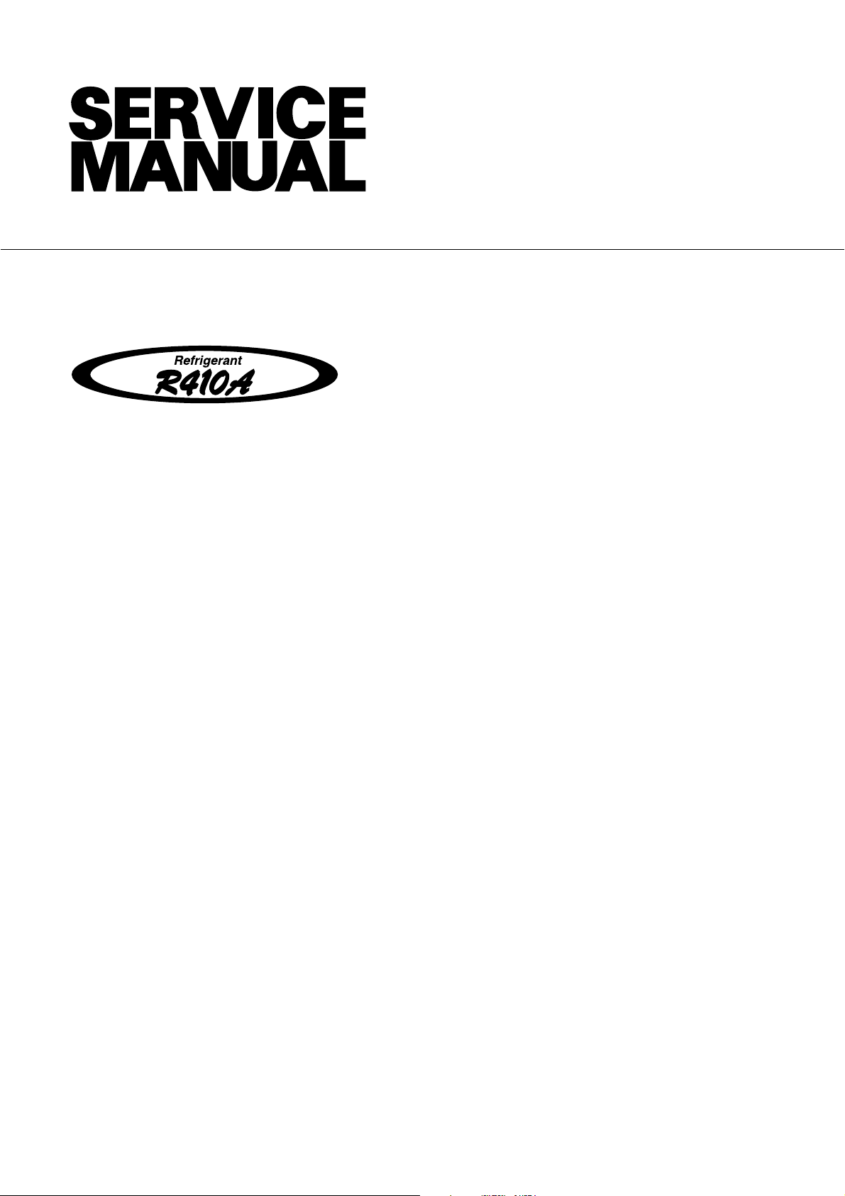
Performance Date
measuring condition, since the defrosting operation starts up at lower than 2 deg C.
Heating
(Capacity curve)
150%
140%
130%
120%
110%
(1 / 2)
100%
Capacity(%)
90%
80%
70%
60%
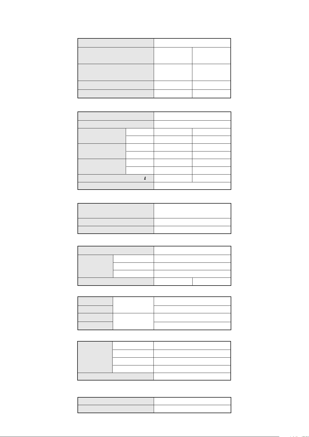
(Input curve)
180%
170%
160%
150%
140%
IndoorDB:20
-10 -5 0 5 10 15 20 25
Outdoor DB( ) RH=85%
C
C
24
130%
120%
Input(%)
110%
100%
90%
80%
-10 -5 0 5 10 15 20 25
Outdoor DB( ) RH=85%
2
C
(Remarks) Above measurement was conducted under the low temperature heating capacity
(it was measured at the compressor maximum frequency, including the defrosting
cycle.)
IndoorDB:20
24
C
Page 4
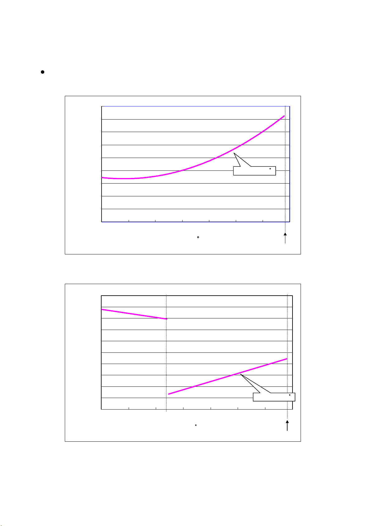
Cooling
(Capacity curve)
150%
140%
130%
120%
110%
(2 / 2)
100%
90%
Capacity(%)
80%
70%
60%
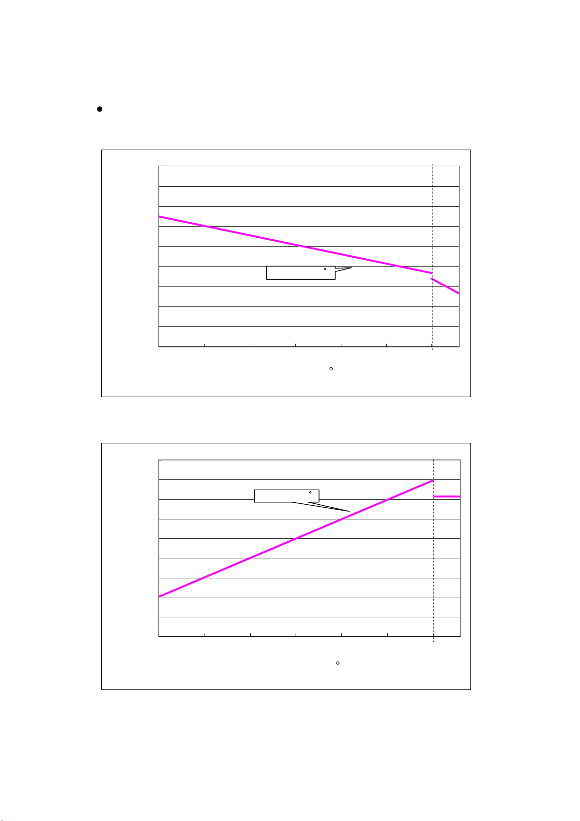
(Input curve)
120%
110%
100%
90%
80%
Indoor:27/19
10 15 20 25 30 35 40
Outdoor DB
Indoor:27/19
C
( )
C
C
43
70%
Input(%)
60%
50%
40%
30%
10 15 20 25 30 35 40
( )
Outdoor DB
C
43
(Remarks) When the outdoor temperature is higher than 40 degC, the current release function
starts to operate and the copressor rotation is decreased, and the capacity goes down.
Page 5
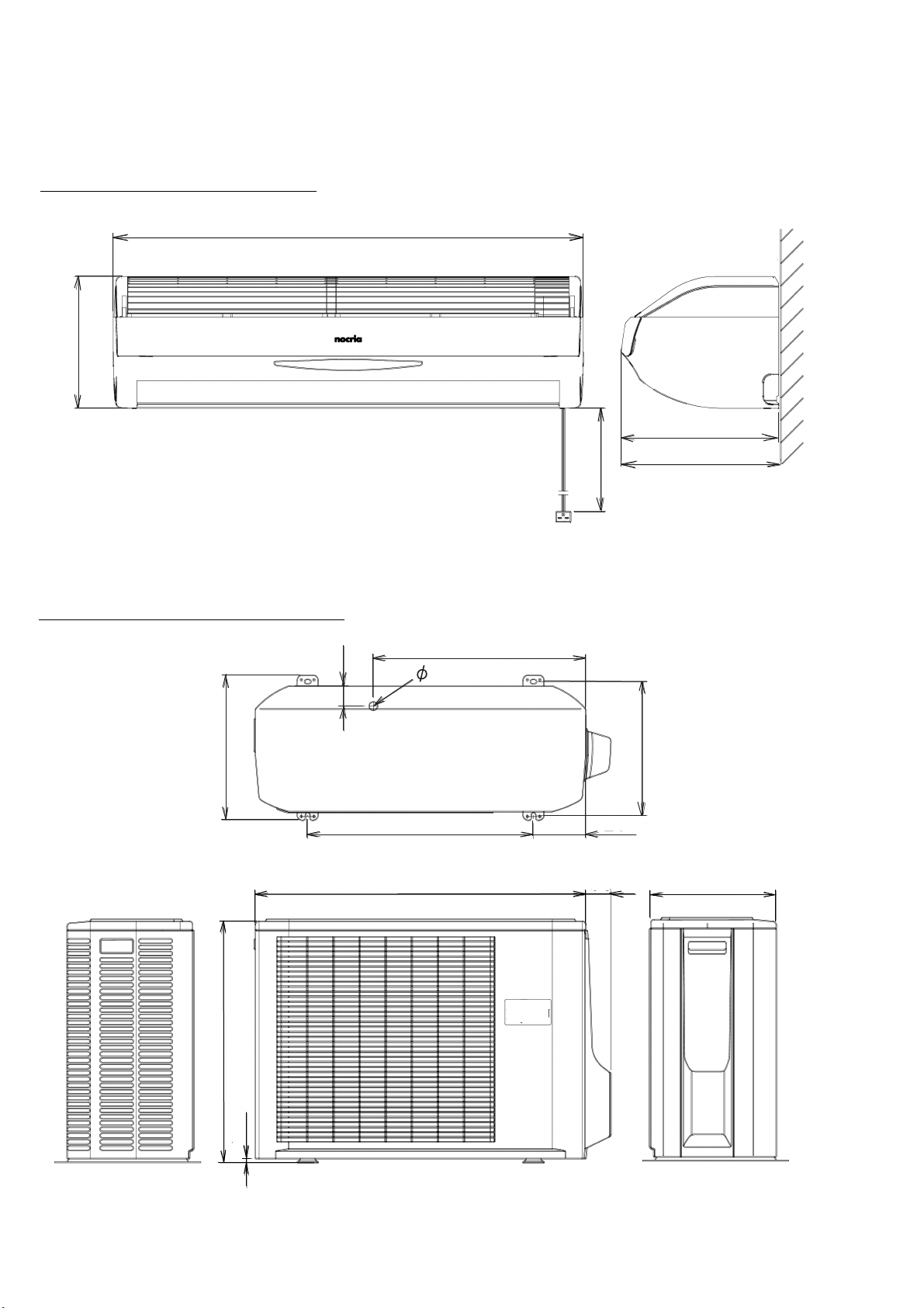
Models : AWY14LSAZ, AWH14LSAZ
AWY17LSAZ, AWH17LSAZ
250
DIMENSIONS
Unit : mm
890
288
292
1400
Models : AOY14LSAWC, AOH14LSAWC
AOY17LSAWC, AOH17LSAWC
347
48
20
320
508
60
125
300
540
790
578
10
- 2 -2003.08.10
Page 6
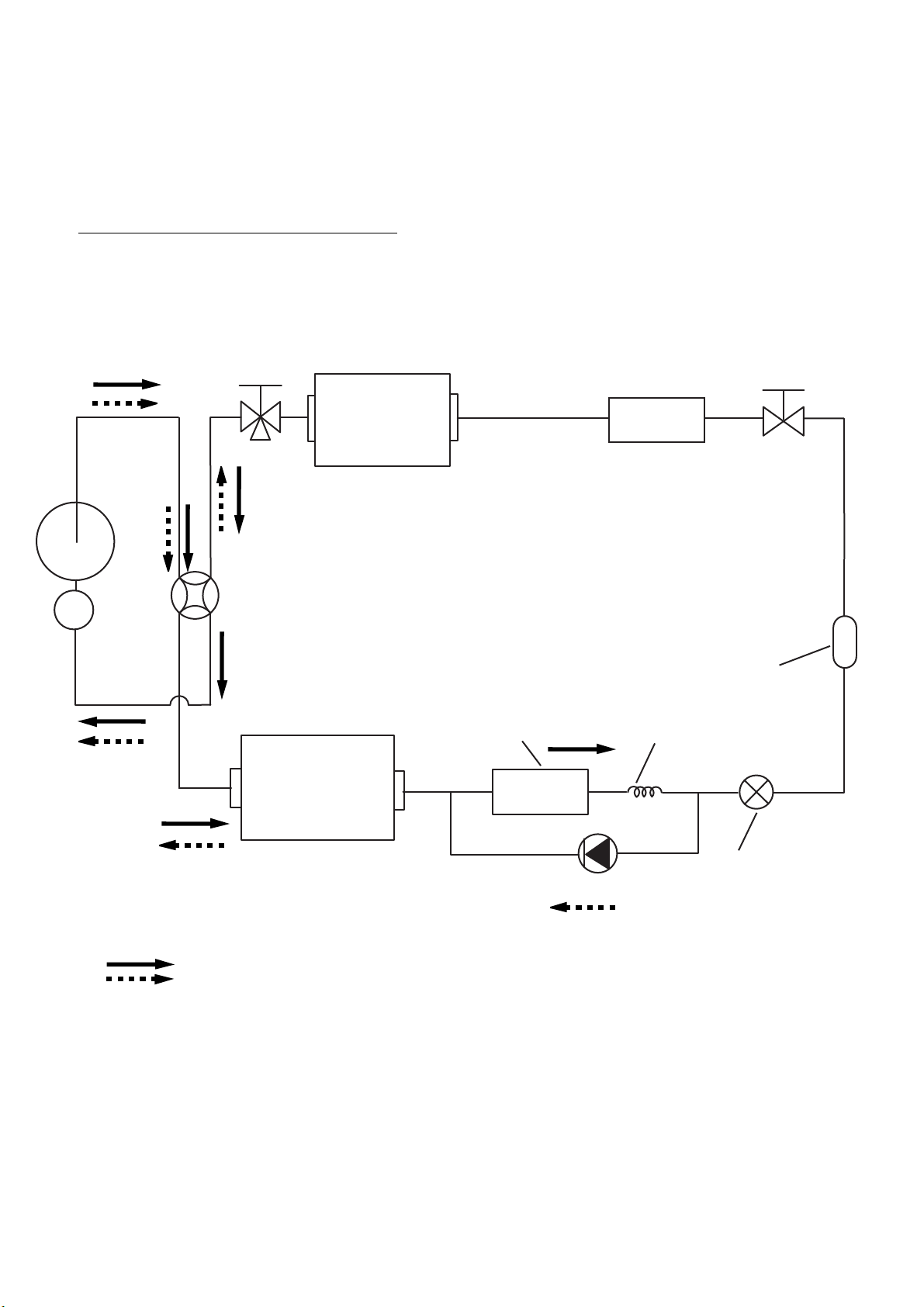
REFRIGERANT SYSTEM DIAGRAM
Models : AWY14LSAZ / AOY14LSAWC
AWH14LSAZ / AOH14LSAWC
AWY17LSAZ / AOY17LSAWC
AWH17LSAZ / AOH17LSAWC
Heat exchanger
3-Way Valve
Compressor
( INDOOR )
Heat exchanger B
( INDOOR )
2-Way Valve
Accumulator
Cooling
Heating
4-Way Valve
Heat exchanger
( OUTDOOR )
Heat exchanger B
( OUTDOOR )
Receiver
Capillary tube
Pulse motor valve
Check valve
2003.09.11
- 3 -
Page 7
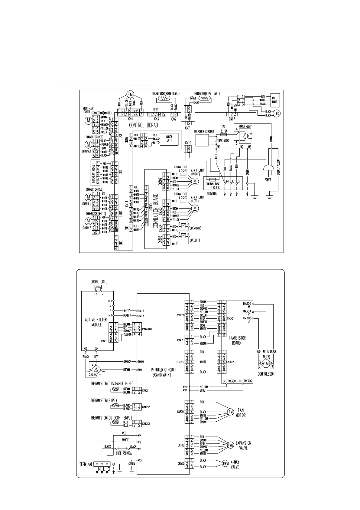
CIRCUIT DIAGRAM
Models : AWY14LSAZ / AOY14LSAWC
AWH14LSAZ / AOH14LSAWC
AWY17LSAZ / AOY17LSAWC
AWH17LSAZ / AOH17LSAWC
2003.08.10
- 4 -
Page 8

I N D O O R P R I N T E D C I R C U I T B O A R D
C I R C U I T D I A G R A M
Models : AWY14LSACW, AWH14LSACW
AWY17LSACW, AWH17LSACW
TERMINAL BOARD
GREEN
BLUE
BROWN
WHITE
RED
BLACK
POWER SOURCE
220 / 240V
50 / 60Hz
UV
UNIT
MINUS ION
UNIT
TERMINAL FUSE
GRAY
GRAY
RED
WHUTE
WHUTE
RED
WHUTE
WHUTE
CONTROLLER PCB ASSEMBLY ( MAIN PCB )
EZ-35HSE-C
MANUAL AUTO
SWITCH
RED
WHITE
RED
WHT
WHT
WHT
WHT
WHT
BLACK
BLACK
ROOM TEMPERATURE THERMISTOR
PIPE TEMPERATURE THERMISTOR-A
GRAY
GRAY
INDICATOR PCB
EZ-0035HSE-D
FAN MOTOR
RED
BLACK
WHITE
YELLOW
PURPLE
REMOTE CONTROL
SWITCHING
PLUG ON
RED
WHT
WHT
WHT
WHT
WHT
WHT
WHT
WHT
RED
WHT
RED
WHITE
WHITE
WHITE
WHITE
RED
WHITE
WHITE
WHITE
BROWN
RED
ORANGE
YELLOW
GREEN
BLUE
PURPLE
GRAY
WHITE
BLACK
WHITE
FLAP-U
UP / DOWN
FLAP-Z
UP / DOWN
LOUVER
L - R
DIFFUSER
WHITE
BROWN
RED
ORANGE
YELLOW
FILTER CLEAN
WHT
BRW
RED
ORG
FILTER CLEAN
RED
WHITE
RED
WHITE
2003.09.05
- 5 -
Page 9

Models : AOY14LSAWC, AOH14LSAWC
AOY17LSAWC, AOH17LSAWC
1
POWER SOURCE
AC220 / 240V
50Hz
2
3
TERMINAL
HPT3031-3-L3
FAN MOTOR
F M
4-WAY VALVE
EXPANSION VALVE
M
POWER
POWER
SERIAL
F201
FH-153A
20A-250V
EARTH
UL1015
AWG14
BLACK
UL1015
AWG14
WHITE
UL1015 AWG20
RED
UL1015 AWG16
GREEN
RED
BLACK
WHITE
YELLOW
BROWN
BLACK
BLACK
RED
BROWN
BLUE
ORANGE
YELLOW
WHITE
W1
(A-1)
W2
(B-1)
W4
B
(D-1)
W3
B
(C-1)
CN800
B5(7-2.3)B-XASK-1-A
(H-1)
1
CN500
B2P3-VH-B-C
2
(F-7)
3
CN700
B6B-XARK-1-A
(I-1)
O U T D O O R P R I N T E D C I R C U I T B O A R D
C I R C U I T D I A G R A M
INVERTER UNIT
CHOKE COIL
W201
UL1015
AWG12
+
-
W202
UL1015
AWG12
RED
BLACK
+
L1
-
L2
IC404
SACT32010A
ACTPM
P
N1
N2
I O
CN11
CONTROLLER PCB ASSEMBLY
AOY(H)14LSAWC : EZ-002UHUE-C
AOY(H)17LSAWC : EZ-002THSE-C
W12
W13
UL1015 AWG14
UL1015 AWG14
W401
UL1007 AWG24
UL1007 AWG24
UL1007 AWG24
UL1007 AWG24
BROWN
RED
ORANGE
YELLOW
WHITE
PURPLE
TM12
(A-9)
TM13
(B-9)
CN80
B3(7.5)B-XAKK-1-A
(F-16)
CN400
B4B-XASK-1-A
(E-11)
CN70
B9B-XAKK-1-A
(I-16)
CN71
B3B-XASK-1-A
(H-16)
W20
(A-15)
W21
(B-15)
1
2
3
UL1015 AWG14
YELLOW
UL1015 AWG14
BLUE
TM11
(B-7)
TM10
(A-7)
W11
UL1015
AWG12
BROWN
W10
UL1015
AWG12
ORANGE
D201
D25VB60
RED
WHITE
BLACK
W302
UL1007
AWG24
BROWN
RED
ORANGE
YELLOW
GREEN
BLUE
PURPLE
GRAY
WHITE
BLACK
BROWN
W301
UL1007
AWG24
TM301
(C-9)
TM302
(C-9)
CN302
B3(6.0)B-PASK-1
(F-12)
CN301
B11B-PASK-1
(F-4)
TR PCB
EZ-002THUE-TR
TM305
(C-9)
TM304
(C-9)
TM303
(C-9)
RED
U
WHITE
V
BLACK
W
EMI FILTER
ZCAT2132-1130
COMPRESSOR
C M
PEX-125F
2003.09.05
DISCHARGE TEMPERATURE THERMISTOR
PIPE TEMPERATURE THERMISTOR
OUTDOOR TEMPERATURE THERMISTOR
-0
-0
-0
BROWN
BROWN
BLACK
BLACK
BLUE
BLUE
CN21
B2B-XH-AM YELLOW
(K-1)
CN22
B2B-XH-AM RED
(K-1)
CN23
B2B-XAEK-1-A
(K-1)
- 6 -
Page 10

Models : AOY14LSAWC, AOH14LSAWC
AOY17LSAWC, AOH17LSAWC
CONTROLLER PCB ASSEMBLY
AOY(H)14LSAWC : EZ-002UHUE-C
AOY(H)17LSAWC : EZ-002THSE-C
L
N W2
EARTH W3
SERIAL
B5(7-2.3)B-XASK-1-A
CN800
FAN MOTOR
B6B-XARK-1-A
CN700
EXPANSION VALVE
CN24
B2B-XASK-1-A
SUCTION
TEMPERATURE
THERMISTOR
CN21
B2B-XH-AM
YELLOW
DISCHARGE
TEMPERATURE
THERMISTOR
CN22
B2B-XH-AM
RED
PIPE
TEMPERATURE
THERMISTOR
CN23
B2B-XAEK-1-A
OUTDOOR
TEMPERATURE
THERMISTOR
W1
W4
POWER
VA1
C100
VA2
SA100
D13
SERIAL COMMUNICATION
18
R800
100K
D800
<2W>
JM800
12V
K800
C802
15V
0.1
<F>
L800
BL02Rn1
12V
EXPANSION VALVE DRAIVE
R71
56K (1%)
<1/10W>
5V
L70
BL02Rn1
C53
0.1
<F>
THERMISTOR
C101
C102
14
DC-3
C800
+
100/
16V
R804 1.0K
<1/10W>
R63
6.65K (1%)
<1/10W>
L1
HY I C 1
10
AC-
DC FAN COMMUNICATION
15V
R801 1.0K
<1/4W>
R802
5V
560
<1/10W>
R803
10K
<1/10W>
C801
0.01
<B>
01
02
03
04
GND1
GND2
GND3
GND4
IC700
R70 10K <1/10W>
R62 10K <1/10W>
R64 10K <1/10W>
R65
<1/10W>
R66 10K <1/10W>
R67
38.3K (1%)
<1/10W>
C103
Q801
DTA143EUA
11
12
13
14
COM1
COM2
NC1
NC2
W5
L2
5VAC+
5V
D600
DAN217U
JM10 - JM18
JM20 - JM28
W6
543
Q800
DTA143EUA
R700 1.5K <1/10W>
R701 1.5K <1/10W>
R702 1.5K <1/10W>
12V
R703 1.5K <1/10W>
C68
C106
2
C66
0.1
<F>
AC+
C104
C105
1
<1/10W> x 3
C67
0.1
<F>
R51
4.7K
C65
0.1
<F>
L3
C107
AC-
CT1
5V
R54
R50
10K
10K
R53 1.0K
<1/10W>
AC+
F3 3A
JM3
MODEL SWITCHING
R100
ZPR0RCH400
-0
K101
C108
12V
D60
DAN217U
R60
<1/10W>
CURRENT DETECTOR
R52 1.0K
<1/10W>
C51
0.1
<F>
4-WAY VALVE DRIVER
K500
12V
D501
D503
LED DRIVE
R107 1.0K
<1/10W>
R106 1.0K
<1/10W>
R105 1.0K
<1/10W>
R104 1.0K
<1/10W>
R103 1.0K
<1/10W>
R102 1.0K
<1/10W>
R101 1.0K
<1/10W>
5V
C52
0.1
<F>
JM501
12V
5V
D500
C109
R69
<1/10W>
C60
220/
16V
CN500
B2P3-VH
-B-C
4-WAY VALVE
JM107
JM106
JM105
JM104
JM103
JM102
JM101
TEST
JM100
+
D502
D504
D28
<RED>
W14
W15
TM10
W10
W11
TM11
VR1
B2K
JM60
R61
<1/10W>
AC-
JM500
R43 2.2K
<1/10W>
R108 10K
<1/10W>
5V
R18 10K
<1/10W>
R68 22K
<1/10W>
C64
0.1
<F>
C55
0.1
<F>
C54
0.1
<F>
D402
RD3.3ES
<B2>
R500 470
<RS-3W>
JM504
JM502
12V
CR500
ULN2003ANS
IC3-1
IC3-2
IC3-6
IC3-5
IC3-7
IC3-4
IC3-3
R72 1.0K
<1/10W>
C17
0.1
<F>
15V
R403
2.7K
<1/4W>
R501 470
<RS-3W>
JM505
K501
C16
4.7/
50V
C409
+
10/
25V
RESET
DC-1
R400 180K
<RN-1/2W>
R401 180K
<RN-1/2W>
R402
<1/10W>
+
TM12
W12
W13
TM13
SHUT OFF DETECTOR
R404 1.0K
<1/10W>
JM503
X1
8.00MHz
R73 100K
<1/10W>
VDD
NC
GND
OUT
IC5
S80842
POWERPOWER
C411
0.01
<F>
5V
C201
+
IC400-1
-
+
-
+
IC400-2
R409 1.0K
<1/4W>
Q401
DTC124EUA
C415
1000P
<B>
R411 22K
<1/10W>
I C 1
P63
VCC
P62
AVCC
P00
P46
P12
P01
P17
P50
P13
P37
P14
P36
P15
P40
P16
MD2
AVR
P11
P24
P26
P25
P02
P30
P03
P31
P04
P32
P05
P33
P06
P34
P07
P35
P10
P60
C
P20
P61
P21
MD0
MD1
P22
P44
P23
P57
P43
P56
P42
P55
P41
P54
P45
P52
RSTX
P27
P53
AGND
P51
X0
GND
X1
GND
+
C202
D300
DAN217U
5V
R405
10K
<1/10W>
C402
0.01
<F>
ACTIVE START
JM400
A
Q402
DTC124EUA
C414
R410 22K
<1/10W>
1000P
<B>
5V
R303 1.0K
<1/10W>
C300
R302
0.1
3.83K
<F>
(1%)
<1/10W>
18V
C80
100P
<CH>
DC-3
5V
Q403
DTA143EUA
A
18V
R408 180
<1/10W>
A
R95 1.0K
<1/10W>
R80 27K
<1/10W>
5V
R56 10K
<1/10W>
5V
D
DC VOLTAGE DETECTOR
R300 195K
<RN-1/2W>
R301 195K
<RN-1/2W>
R304 10K
<1/10W>
Q1
2SC4236
R6
R7
<1/2W>
C400
0.1
<F>
<1/2W>
CN400
B4B-XASK
-1-A
ACTPM
CONTROL
ACTIVE VOLTAGE CONTROL
C413
5V
A
R96 4.7K
<1/10W>
Q80
2SC2412K
<BQ>
C18
0.1
5V
<F>
C50
0.1
<F>
C19
+
4.7/
50V
<PS>
C602
C603
C604
5V
R59
1.0K
R57 10K
<1/10W>
R606 1.0K
<1/10W>
DC-3
D1
15V
R81 22K
<1/10W>
IC80-1
R82 1M
<1/10W>
IC80-2
R600
10K
<1/10W>
IC600
CS
SK
D1
NC
JM600
C601
0.01 <F> x 4
R42
R58
10K
10K
<1/10W> x 3
5V
R605 10K
<1/10W>
R607 1.0K
<1/10W>
R202
220K
<2W>
D1FL20U
-
+
-
+
VCC
D0
NC
GND
DC-1
R1 220K
<2W>
D10
RD5.6ES
C85
4.7/
50V
JM1
JM2
R3 100
<1W>
<B2>
R4
330
<1/4W>
+
5V
C600
0.1
<F>
5V
R603 10K
<1/10W>
F1
15A - 250V
R2 1.0K
<RS-3W>
C1 220P
<BN>
C2
<ECQB>
D2
D1FL20U
C3
100/
16V
D
15V
C86
470P
<B>
C84
0.1
<F>
EEPROM
DC-2
POWER SWICHING
+
D81
D82
DAN217U
DAN217U
C87
330P
<B>
4.7K <1/10W> x 6
5V
R609 22K
<1/10W>
F2 3A
FH1
F4
BET 3.15A - 250V
T1
15V
D7
D1FL20U
C8
+
220/
35V
DC-2
L80
R86
8.66K (1%)
<1/10W>
IPM DRIVE SIGNAL
R74
R75 R79R78
IPM TRIP SIGNAL
5V
R604 10K
<1/10W>
FH2
R83 195K
<RN-1/2W>
R84 195K
<RN-1/2W>
R76
DC-3
D3
D2FL20U
D4
D1FL20U
R5 10K
<1/10W>
D5
D1FL20U
D6
D1FL20U
R93
5.76K (1%)
<1/10W>
R94
143 (1%)
<1/10W>
R77
C5
220/
16V
IC407
uPC24M18
15V-2
C406
+
+
C9
100/35V
220/
50V
PLACE DETECTOR
R88 195K
<RN-1/2W>
R90 195K
<RN-1/2W>
R92 192K
<RN-1/2W>
5V
5V
R40 1.0K
<1/10W>
C33
0.01
<F>
FLASH WRITE
C207
0.1
<HCP>
+
I
O
G
R33 4.7K
<1/10W>
IC7
TA7805
I
C4
+
470/
25V
D403
ZP1027
R87 195K
<RN-1/2W>
R89 195K
<RN-1/2W>
R91 195K
<RN-1/2W>
G
W20
W21
18V
+
O
C34
0.01
<F>
C418
10/
35V
A
12V
5V
C71
0.1
<F>
C70
0.1
<F>
+
15V
C6
100/
16V
5V
5V
CN80
B3(7.5B)
-XAKK-1-A
PLACE DETECTION
SIGNAL
CN71
B3B-XASK-1-A
IPM POWER
CN70
B9B-XAKK-1-A
IPM CONTROL
CN600
B10B-PASK-1
TAUX
TTXD
TRXD
TMODE
TAUX3
TCK
/ TRES
/ TICS
2003.09.05
- 7 -
Page 11

Models : AOY14LSAWC, AOH14LSAWC
AOY17LSAWC, AOH17LSAWC
TR PCB ASSEMBLY
EZ-002THUE-TR
5V
GND
F0
WN
VN
UN
WP
VP
UP
15V
GND
CN301
B11B-PASK-1
C300
0.1
<F>
5V
15V
R360 39
<1/2W>
15V
C301
0.1
<F>
15V
5V
R303
4.7K
<1/10W>
D301
U1JU44
D302
U1JU44
D303
U1JU44
R316 1.0K <1/10W>
R317 1.0K <1/10W>
R318 1.0K <1/10W>
R319 1.0K <1/10W>
R320 1.0K <1/10W>
5V
R321 1.0K <1/10W>
C311
2200P
<B>
C312
2200P
<B>
R362 330K
<1/10W>
C321
0.1
<F>
C313
2200P
<B>
C314
2200P
<B>
C303
47/
35V
C315
2200P
<B>
R363 330K
<1/10W>
C322
0.1
<F>
+
C316
2200P
<B>
C304
47/
35V
C324
0.1
<F>
R361 330K
<1/10W>
C323
0.1
<F>
+
15V
C325
0.1
<F>
C305
47/
35V
15V 15V
C326
0.1
<F>
+
IC301
PS21246-E
UP
VP1
VUFB
VUFS
VP
VP1
VVFB
VVFS
WP
VP1
VPC
VWFB
VWFS
TM301
TM302
TM303
TM304
TM305
VN1
VNC
C I N
CFO
FO
UN
VN
WN
P
U
V
W
N
C327
0.022
<F>
P
N
W
V
U
15V
C332
0.1
<F>
R301 15M
<5W>
C328
2200P
<B>
R302 1.0K
<1/10W>
D307
ZP1027
C207
HCP 104
2003.09.05
CN302
R3(6.0)B-PASK-1
- 8 -
Page 12

E R R O R C O N T E N T S
Self-diagnosis function
This function memorizes the trouble diagnosis function (Flashing LED display) when trouble occurs at an indoor unit PC board. (The memory contents are not erased even when the power cord is disconnected from the
power outlet.)
The self-diagnosis function (LED display) allows detailed diagnosis by allowing switching to large division indication and small division indication.
Self-diagnosis function [LED display] (How to call memory)
(1)When trouble occurs, it is displayed by [Operation lamp (red)], [Timer
lamp (green)], and temperature monitor (7 segments display) 2 digits.
(2)After the power plug is pulled, operation starts by remote control. [Nor-
mal operation display]
(3)When the [Test run] button on the back of the remote controller is
pressed, [Memory contents] display is performed.
*When there is no error memory memorization, the unit enters the
[Test run] state.
Memory erase method
(1)The memory contents can be erased by pressing the [Service end but-
ton-emergency operation] button on the body for 3 seconds or longer
during self-diagnosis function display. (The indoor unit buzzer buzzes
for 3 seconds.)
*For 1 minute after trouble reset, the temperature and humidity moni-
tor displays [--]. After 1 minute, the temperature and humidity monitor
is displayed.
2003.09.16
9
Page 13

Self-diagnosis function table (LED display)
[Small division indication] [Table 2]
(1 / 3)
Operation cause: Indoor and
outdoor unit connection wire
Outdoor unit
Reset when serial (reverse)
becomes normal.
Operation cause: Indoor and
outdoor unit connection wire
Reset when serial (reverse)
becomes normal.
Operation cause: Indoor unit
Reset when serial (forward)
becomes normal.
Operation cause: Indoor unit
Reset when serial (forward)
becomes normal.
Operation cause: Indoor unit
Reset when detected value be-
comes normal.
Operation cause: Indoor unit
Reset when detected value be-
comes normal.
Operation cause: Outdoor unit
Reset when detected value be-
comes normal.
Operation cause: Outdoor unit
Error judgement Body operation
When the serial signal is not
read even once within 7 sec-
onds from power relay ON after
operation starts.
Serial (reverse) error 7 seconds
after power relay ON.
When serial signal (forward) is
not read within 10 seconds af-
ter power relay ON.
Serial (reverse) error 10 sec-
onds after power relay ON.
When thermistor detected val-
ue open (Detected only when
power on)
When thermistor detected val-
ue open or shorted (Detected
only when power on)
When thermistor detected val-
ue open or shorted (constantly
detected)
When thermistor detected val-
Reset when detected value be-
comes normal.
Operation cause: Outdoor unit
Reset when detected value be-
comes normal.
ue open (constantly detected)
When thermistor detected val-
ue open or shorted (constantly
detected)
02
Temperature
monitor display
Operation : 0.1 sec
Timer : 0.5 sec 2 times
03
Operation : 0.1 sec
Timer : 0.5 sec 3 times
04
Operation : 0.1 sec
Timer : 0.5 sec 4 times
05
Operation : 0.1 sec
Timer : 0.5 sec 5 times
22
Operation : 0.1 sec
Timer : 0.5 sec 2 times
23
Operation : 0.1 sec
Timer : 0.5 sec 3 times
32
Operation : 0.1 sec
Timer : 0.5 sec 2 times
33
Operation : 0.1 sec
Timer : 0.5 sec 3 times
34
Operation : 0.1 sec
Timer : 0.5 sec 4 times
Small division indication
error immediate-
ly after operation
02 to 07
Temperature
monitor display
Serial (reverse)
error during op-
eration
Serial (forward)
error immediate-
ly after operation
Serial (forward)
error during op-
eration
Room tempera-
ture thermistor
faulty
Piping thermistor
(intermediate)
faulty
Outlet thermistor
faulty
Heat exchange
thermistor faulty
Outside air ther-
mistor faulty
22 to 25
32 to 37
Display Display
2004.05.19
Operation : ON
Timer : 1 sec ON/OFF
Operation : 0.5 sec 2 times
Timer : 0.1 sec
Operation : 0.5 sec 3 times
Timer : 0.1 sec
Large division indication
Serial signal error Serial (reverse)
Indoor unit
thermistor abnormal
Outdoor unit
thermistor abnormal
10
Page 14

(2 / 3)
Operation cause: Indoor unit
Other than display operate nor-
mally.
Display performed only during
normal operation. Goes off if
operation stops.
Operation cause: Indoor unit
Permanent stop
Error judgement Body operation
When filter reset ? forced auto-
matic SW is ON for 30 secs or
more
When serial signal (reverse) in-
put even though mail relay OFF
Operation cause: Indoor unit
Permanent stop
condition after 2 mins after op-
eration stopped.
When power frequency
(50/60Hz) cannot be judged
Operation cause: Outdoor unit
Permanent stop
even after 2 secs have elapsed
after power was turned on.
When outdoor unit overcurrent
2nd operation occurs within 40
secs from starting and 3rd op-
Operation cause: Outdoor unit
Permanent stop
eration occurs within 15 mi-
nutes
When current during operation
1 min or more after compressor
starts is 0A
42
Temperature
monitor display
Operation : 0.1 sec
Timer : 0.5 sec 2 times
43
Operation : 0.1 sec
Timer : 0.5 sec 3 times
44
Operation : 0.1 sec
Timer : 0.5 sec 4 times
52
Operation : 0.1 sec
Timer : 0.5 sec 2 times
53
Operation : 0.1 sec
Timer : 0.5 sec 3 times
Small division indication
Filter reset -
forced automatic
switch faulty
Temperature
monitor display
Main relay
welded
Power interrupt
faulty
42 to 48
Transistor mod-
ule overcurrent
52 to 57
Outdoor unit in-
put current ab-
normal
Display Display
2004.05.19
Operation : 0.5 sec 4 times
Timer : 0.1 sec
Operation : 0.5 sec 5 times
Timer : 0.1 sec
Large division indication
Indoor unit control
unit faulty
Outdoor unit
control unit faulty
11
Page 15

(3 / 3)
Operation cause: Outdoor unit
Permanent stop
Operation cause: Outdoor unit
Permanent stop
Operation cause: Outdoor unit
Permanent stop
Operation cause: Outdoor unit
Permanent stop
Operation cause: Outdoor unit
Permanent stop
Operation cause: Outdoor unit
Compressor stopped
During 3 mins delay
Operation cause: Outdoor unit
Permanent stop
Error judgement Body operation
When position detection abnor-
mal 2nd operation occurs within
40 secs from starting
When fan motor current, posi-
tion detection, or abnormal op-
erated 2 times within 10 mins
When detected value after 56
secs after fan motor starts is
0 r.p.m.
When detected speed after 56
secs after fan motor starts is
1/3 or less of target speed
When compressor stopped 2
times by discharge protection
Cooling excessive high pres-
sure rise protection operated
and displayed in 3 mins delay
When 4-way valve switching per-
formed and operated 5 times con-
secutively when room temperature
and indoor unit piping thermistor
Operation cause: Outdoor unit
Permanent stop
C or
o
temperature difference of 10
When active filter output volt-
age abnormal (300V or more,
more detected
Operation cause: Outdoor unit
Permanent stop
or 80V or less) operated 2 con-
secutive times within 40 secs
Active filter abnormal / active fil-
ter instant interruption abnormal
Operation cause: Outdoor unit
Permanent stop
200V model: When 100V
impressed
Operation cause: Outdoor unit
Permanent stop
100V model: When 200V
impressed
When model information ROM
on control board cannot be read
55
Temperature
monitor display
Operation : 0.1 sec
Timer : 0.5 sec 5 times
Small division indication
Compressor po-
sition abnormal
52 to 57
Temperature
monitor display
56
Operation : 0.1 sec
Timer : 0.5 sec 6 times
Outdoor unit fan
abnormal
62
Operation : 0.1 sec
Timer : 0.5 sec 2 times
Fan motor
locked
62 to 63
63
Operation :0.1 sec
Timer : 0.5 sec 3 times
Fan speed ab-
normal
Operation : 0.1 sec
Discharge tem-
72 to 75
72
Timer : 0.5 sec 2 times
perature
73
Operation : 0.1 sec
Timer : 0.5 sec 3 times
abnormal
Cooling exces-
sive high pres-
sure rise protec-
tion faulty
74
Operation : 0.1 sec
Timer : 0.5 sec 4 times
DC 4-way valve,
solenoid value
faulty
82
Operation : 0.1 sec
Timer : 0.5 sec 2 times
Active filter volt-
age detection ab-
normal (when op-
82 to 83
83
Operation : 0.1 sec
Timer : 0.5 sec 3 times
erated 2 times)
Active filter voltage
detection abnor-
mal (1 time instant
AA
_____
_____
operation)
AA
Ab
_____
_____
Ab
Display Display
2004.05.19
Operation : 0.5 sec 5 times
Timer : 0.1 sec
Operation : 0.5 sec 6 times
Timer : 0.1 sec
Operation : 0.5 sec 7 times
Timer : 0.1 sec
Operation : 0.5 sec 8 times
Timer : 0.1 sec
Operation :0.1 sec
Dash: 0.1 sec
Indoor unit buzzer sound
Operation:0.1 sec
Timer: 0.1 sec
Dash: 0.1 sec
UV negative ion: 0.1 sec
Large division indication
Power supply voltage
Outdoor unit
thermistor abnormal
Indoor unit fan motor
abnormal
Refrigerating cycle
abnormal
Active filter abnormal
abnormal
Outdoor unit control
unit board faulty
12
Page 16

How to take UV unit to pieces
UV unit
Screws
Take off screws, and take out UV unit.
UV unit
UV unit
Screws
Lamp cover
Lamp
Take off screws, and take out Control box (with lamp) from lamp cover.
Control box
- 13 -2003.11.11
Page 17

UV lamp and control box
Take off screws, and pull lamp out of control box.
- 14 -2003.11.11
Page 18

Models : AWY14LSAZ, AWH14LSAZ
2003.09.09
AWY17LSAZ, AWH17LSAZ
1
Top Grill
D I S A S S E M B L Y I L L U S T R A T I O N
1
Air Filter
9
15
9
Dust Box Assy
56
Top Cover 8
2
Top Panel
Open Panel
6
Dust Box Assy
Air Filter
56
Decoration Plate
7
Front Panel
5
Page 19

2003.09.09
UV Lamp Cover
Models : AWY14LSAZ, AWH14LSAZ
Duct Assy
Casing
57
Bearing-C
13
39
45
Evaporetor Holder-R
UV Unit
Evaporetor
51
Crossflow Fan
52
53
50
Fan Motor
( Brushles Motor )
Bracket Panel
25
Rear Blacket
22
54
Evaporetor Holder-L
AWY17LSAZ, AWH17LSAZ
- 16 -
Casing Cover-F
Drain Pan
14
15
12
Connector Box
Casing Cover-R
20
Louver Cum
Bushing-A
Louver Frame
32
17
Spring Holder
21
46
24
28
Louver L/R
Step Motor
19
Step Motor
27
Drain Cap
16
Casing Cover-B
31
Diffuser-Z
44
Ion Cover
Ionizer
43
46
26
Drain Hose
18
Casing Cover-L
Step Motor
37
Control Box
Control Box Cover
40
Terminal
41
Earth Terminal
36
38
42
Cord Clamp
Room Thermistor Holder
55
Controller PCB Assy
11
Display Case
10
Main Frame
34
Louver-U Assy
30
Louver-U
Shaft
29
Louver-Z
33 Gear Holder
Page 20

2003.09.07
Models : AOY14LSAWC, AOH14LSAWC
AOY17LSAWC, AOH17LSAWC
26
Inverter PCB
TR PCB
31
27
33
Chock Coil
30
PTC
Thermistor
25
Terminal
29
Fuse
19
Separater
9
Protective Net
Propeller Fan
16
Top Panel Seal
Motor Bracket
18
1 Top Panel
Transformer
2
28
ACTPM
13
Condenser
Fan Motor
17
- 17 -
Nut
Grip
Intake Grill
7
4
34
6
Fan Ring
3
Cabinet
Compressor
35
20
Base
Thermistor Spring
24
Cord Clamp
23
Valve Bracket
15
38
10
Expansion Valve Coil
Discharge
Temp. Thermistor
4-Way Valve
32
11
Expansion Valve
14
Thermistor Spring-A
37
Heat Exchanger Thermistor
36
Emblem
39
Solenoid Coil
Dryer
12
3-Way Valve
21
22
2-Way Valve
Cabinet-R
5
8
Switch Cover
Page 21

PARTS LIST
INDOOR UNIT
Ref.
Description
No.
1 Top Grill 9311962014 9311962014
2 Top Panel 9311963011 9311963011
5 Front Panel Assy 9312251025 9312251032
6 Open Panel 9311959021 9311959038
7 Decoration Plate 9311964025 9311964025
8 Top Cover 9311982012 9311982012
9 Air Filter 9311983019 9311983019
10 Main Frame 9311973010 9311973010
11 Display Case 9312009015 9312009015
12 Connector Box 9312008018 9312008018
13 Casing total Assy 9312240012 9312240012
14 Drain Pan total Assy 9312241019 9312241019
15 Casing Cover-F 9312023011 9312023011
16 Casing Cover-B 9312022014 9312022014
17 Casing Cover-R 9312403011 9312403014
18 Casing Cover-L 9312021017 9312021017
19 Step Motor ( MP24ZAN ) 9703477010 9703477010
20 Louver Cam 9312000012 9312000012
21
Spring Holder 9311999010 9311999010
22 Bracket Panel 9312011018 9312011018
24 Bushing-A 9303529010 9303529010
25 Rear Bracket 9312416011 9312416011
26 Drain Hose 9310357019 9310357019
27 Drain Cap 9304150008 9304150008
AWY14LSAZ
9303529010 9303529010
AWH14LSAZ
Part No.
AWY17LSAZ
9311962014 9311962014
9311963011 9311963011
9312251025 9312251032
9311959021 9311959038
9311964025 9311964025
9311982012 9311982012
9311983019 9311983019
9311973010 9311973010
9312009015 9312009015
9312008018 9312008018
9312240012 9312240012
9312241019 9312241019
9312023011 9312023011
9312022014 9312022014
9312403014 9312403014
9312021017 9312021017
9703477010 9703477010
9312000012 9312000012
9311999010 9311999010
9312011018 9312011018
9312416011 9312416011
9310357019 9310357019
9304150008 9304150008
AWH17LSAZ
Ord.
Q'ty
28 Louver L / R 9311997016 9311997016
29 Louver-Z 9311996019 9311996019 9311996019 9311996019
30 Louver-U 9311993018 9311993018
31 Diffuser-Z 9312003013 9312003013
32 Louver Frame 9311994015 9311994015
33 Gear Holder 9311995012 9311995012
34 Louver-U Assy 9312243013 9312243013
36
Room Temp. Thermistor Holder
37 Control Box 9312005017 9312005017
38 Control Box Cover 9312006014 9312006014
39 Bearing-C 9306628017
40 Terminal
41 Earth Terminal 9312809011 9312809011
42 Cord Clamp 9302271002 9302271002
43 Ionizer Assy 9312244010 9312244010
44 Ion Cover 9312185016 9312185016
45 UV Unit 9900144012 9900144012
46 Step Motor ( MP24GA ) 9305780006 9305780006
50 Fan Motor Assy 9601423041 9601423041
51 Crossflow Fan 9312004010 9312004010
52 Evaporator Total Assy 9312776016 9312776016
53 Evaporator Holder-R 9311985013 9311985013
54 Evaporator Holder-L 9311986010 9311986010
55 PCB Assy
(Controller + Connector)
9311948018 9311948018
9306628017 9306628017 9306628017
9306489120
9705164017 9705164017
9306489120
9311997016 9311997016
9311993018 9311993018
9312003013 9312003013
9311994015 9311994015
9311995012 9311995012
9312243013 9312243013
9311948018 9311948018
9312005017 9312005017
9312006014 9312006014
9306489120 9306489120
9312809011 9312809011
9302271002 9302271002
9312244010 9312244010
9312185016 9312185016
9900144012 9900144012
9305780006 9305780006
9601423041 9601423041
9312004010 9312004010
9312776016 9312776016
9311985013 9311985013
9311986010 9311986010
9705164024 9705164024
56 Dust Box Assy 9312787012 9312787012
57 Duct Assy 9312412013 9312412013
- Gear Box L Assy 9312511013 9312511013
- Gear Box R Assy 9312255016 9312255016
2005.11.17
18
9312787012 9312787012
9312412013 9312412013
9312511013 9312511013
9312255016 9312255016
When you order parts, please make a photocopy of this page
and fill the number of the parts in the "Order" column.
Page 22

OUTDOOR UNIT
Ref.
No.
10 4-Way Valve Assy
11 Expansion Valve Assy 9312340019 9312340019
12 Dryer 9312056002 9312056002
13 Condenser 9312323012
14 Thermistor Spring-A 313728262708 313728262708
15 Thermistor Spring 9300089012 9300089012
16 Propeller Fan 9309909014 9309909014
Description
AOY14LSAWC
Top Panel 9308883025 9308883025
1
Top Panel Seal
2
Cabinet 9308878021 9308878021
3
Blow Down Grill 9308884015 9308884015
4
Cabinet-R 9308879028 9308879028
5
6 Fan Ring 9308885012 9308885012
7 Grip 9308880017 9308880017 9308880017 9308880017
8 Switch Cover 9308882028
9 Protective Net
9312026012
9312571017
9312323012 9312323012
AOH14LSAWC
93092280169309228016
9308882028
9312026012
9312571017
AOY17LSAWC
9308883025 9308883025
9308878021 9308878021
9308884015 9308884015
9308879028 9308879028
9308885012 9308885012
9308882028 9308882028
9312026012
9312571017
9312340019 9312340019
9312056002 9312056002
313728262708 313728262708
9300089012 9300089012
9309909014 9309909014
AOH17LSAWC
93092280169309228016
9312026012
9312571017
9312323012
Part No.
Ord.
Q'ty
17 Nut 9304902003 9304902003
18 Motor Bracket 9308872029 9308872029
19 Separater 9312032013 9312032013
20 Base Assy , Painted 9308869081 9308869081
21 3-Way Valve Assy 9313067014 9313067014
22 2-Way Valve Assy 9313062019 9313062019
24 Cord Clamp 9307271014 93072710149307271014
25 Terminal 9306489038 9306489038
26 Inverter PCB Assy 9704936035 9704936035
27 TR PCB Assy 9704949035 9704949035 9704949035 9704949035
28 ACTPM 9703457012 9703457012
29 Fuse 0600036027 0600036027
30 PTC Thermistor 9900041014 9900041014
Diode bridge 0100122107 0100122107
31
32 Expansion Valve Coil 9900057015
33 Choke Coil 9703458019 9703458019
Fan Motor 9601405030 9601405030
34
Compressor Assy 9313192006 9313192006
35
Emblem 9312633012 9312635016
36
Heat Exchanger Thermistor
37
38
Discharge Temp. Thermistor
39
Solenoid Coil
-
Outdoor Thermistor
9704220028 9704220028
9704219091
9970033018
9900149017
9900057015 9900057015
9704219091
9970033018
9900149017
9304902003 9304902003
9308872029 9308872029
9312032013 9312032013
9308869081 9308869081
9313067014 9313067014
9313062019 9313062019
93007271014
9306489038 9306489038
9704936028 9704936028
9703457012 9703457012
0600036027 0600036027
9900041014 9900041014
0100122107 0100122107
9900057015
9703458019 9703458019
9601405030 9601405030
9313192006 9313192006
9312633012 9312635016
9704220028 9704220028
9704219091
9970033018
9900149017
9704219091
9970033018
9900149017
2005.11.17
When you order parts, please make a photocopy of this page
and fill the number of the parts in the "Order" column.
19
Page 23

S T A N D A R D A C C E S S O R I E S
The following installation accessories are supplied.
Use them as required.
Name and Shape
Wall hook bracket
Remote
control
unit
Battery
Part No.
9312011018
AWY14,17
9312226023
AWH14,17
9312226030
0600185046
Q'ty
1
2
Name and Shape Q'ty
Cloth tape
Tapping scr ew(big)
( 4x20)
apping screw(small)
T
Part No.
9308117007
0700076046
0700019036
11
8
2
Remote control unit
holder
9310082010
1
Drain pipe
(outdoor unit)
9301102000
1
2003.08.11
- 20 -
Page 24

0308G2368
 Loading...