

General AUXA18TATA Installation Manual
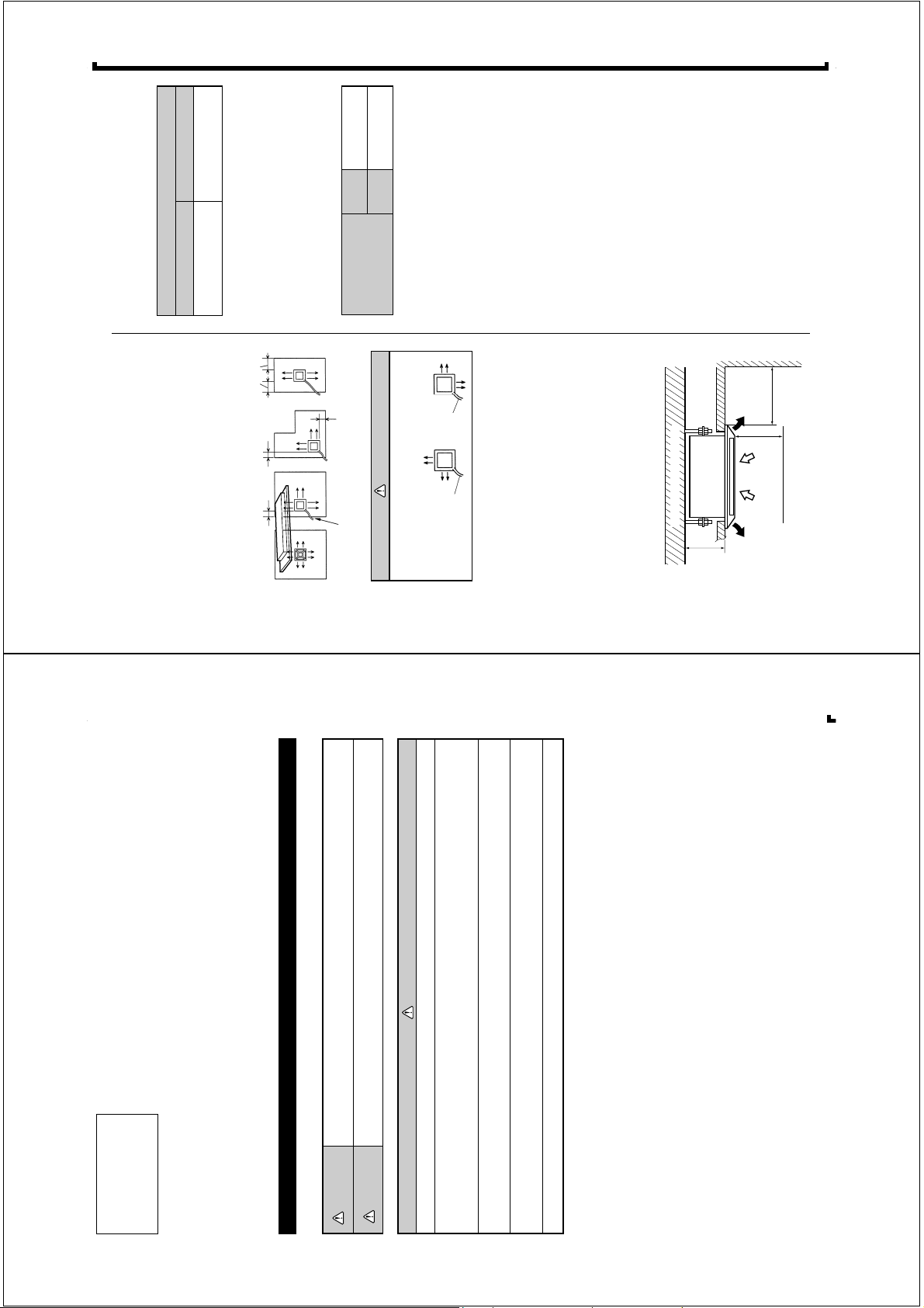
Since 2-way outlet as shown below causes
performance problems, do not set it.
CAUTION
INDOOR UNIT
(1) Install the indoor unit on a place having a sufficient strength
so that it withstands against the weight of the indoor unit.
(2) The inlet and outlet ports should not be obstructed; the air
should be able to blow all over the room.
(3) Leave the space required to service the air conditioner
(Fig. 2).
(4) The ceiling rear height is 9-3/8" inches (250 mm) or more.
(5) A place from where the air can be distributed evenly
throughout the room by the unit.
(6) A place from where drainage can be extracted outdoors
easily.
Fig. 2
SELECTING THE
MOUNTING POSITION
Especially, the installation place is very impor tant for the split
type air conditioner because it is very difficult to move from place
to place after the first installation.
Decide the mounting position together with the customer as
follows:
The discharge direction can be selected as shown below.
Fig. 1
39" (1,000 mm)
or more
4" (100 mm)
or more
4" (100 mm)
or more
(4 directions) (3 directions) (2 directions) (2 directions)
4" (100 mm)
or more
Piping position
Strong and durable ceiling
Obstruction
39" (1,000 mm)
or more
39" (1,000 mm)
or more
9-3/8" (1,000 mm)
or more
CONNECTION PIPE REQUIREMENT
ELECTRICAL REQUIREMENT
Table 1
• Use 0.7 mm to 1.2 mm thick pipe.
• Use pipe with water-resistant heat insulation.
• Use pipe that can withstand a pressure of 3,040 kPa.
MAX
MIN
Connection cord
(mm
2
)
2.5
1.5
••
••
•
Always use H07RN-F or equivalent to the connection cord.
••
••
•
Install the disconnection device with a contact gap of at least
3 mm nearby the units. (Both indoor unit and outdoor unit)
Table 2
Small Large
Diameter
6.35 mm (1/4 in.) 12.7 mm (1/2 in.)
Pipe
Pipe
Cassette Type
R407C
Refrigerant
SPLIT TYPE AIR CONDITIONER
This air conditioner uses new refrigerant HFC (R407C).
INSTALLATION INSTRUCTION SHEET
(PART NO. 9364130026)
For authorized service personnel only.
WARNING
This mark indicates procedures which, if improperly performed, might lead to the death or serious
injury of the user.
This mark indicates procedures which, if improperly performed, might possibly result in personal
harm to the user, or damage to property.
CAUTION!
WARNING!
set available from our standard parts.
only.
standard parts. This installation instruction sheet describes the correct connections using the installation
1 For the air conditioner to operate satisfactorily, install it as outlined in this installation instruction sheet.
2 Connect the indoor unit and outdoor unit with the room air conditioner piping and cords available from our
a flame, it produces a toxic gas.
3 Installation work must be performed in accordance with national wiring standards by authorized personnel
4 If refrigerant leaks while work is being carried out, ventilate the area. If the refrigerant comes in contact with
5 Do not turn on the power until all installation work is complete.
serviced or moved.
• Be careful not to scratch the air conditioner when handling it.
• After installation, explain correct operation to the customer, using the operating manual.
• Let the customer keep this installation instruction sheet because it is used when the air conditioner is
■
■
■
■
WARNING
30 mm
or more
19/32" (15 mm)
Supporter
5 to 6.5 ft
(1.5 to 2 m)
Tra p
6" (150 mm) or less
Max 15"
(400 mm)
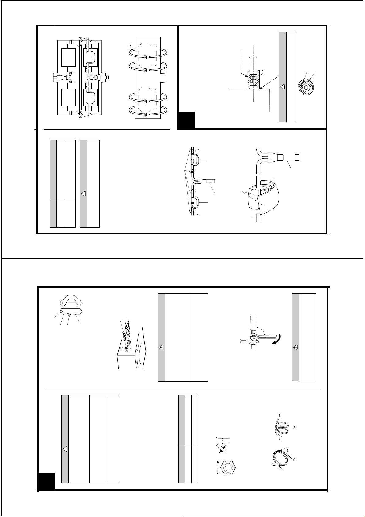
INSTALLING DRAIN PIPE
Install the drain pipe in accordance with the
instructions in this installation instruction sheet
and keep the area warm enough to prevent
condensation. Problems with the piping may lead
2
(Fig. 6).
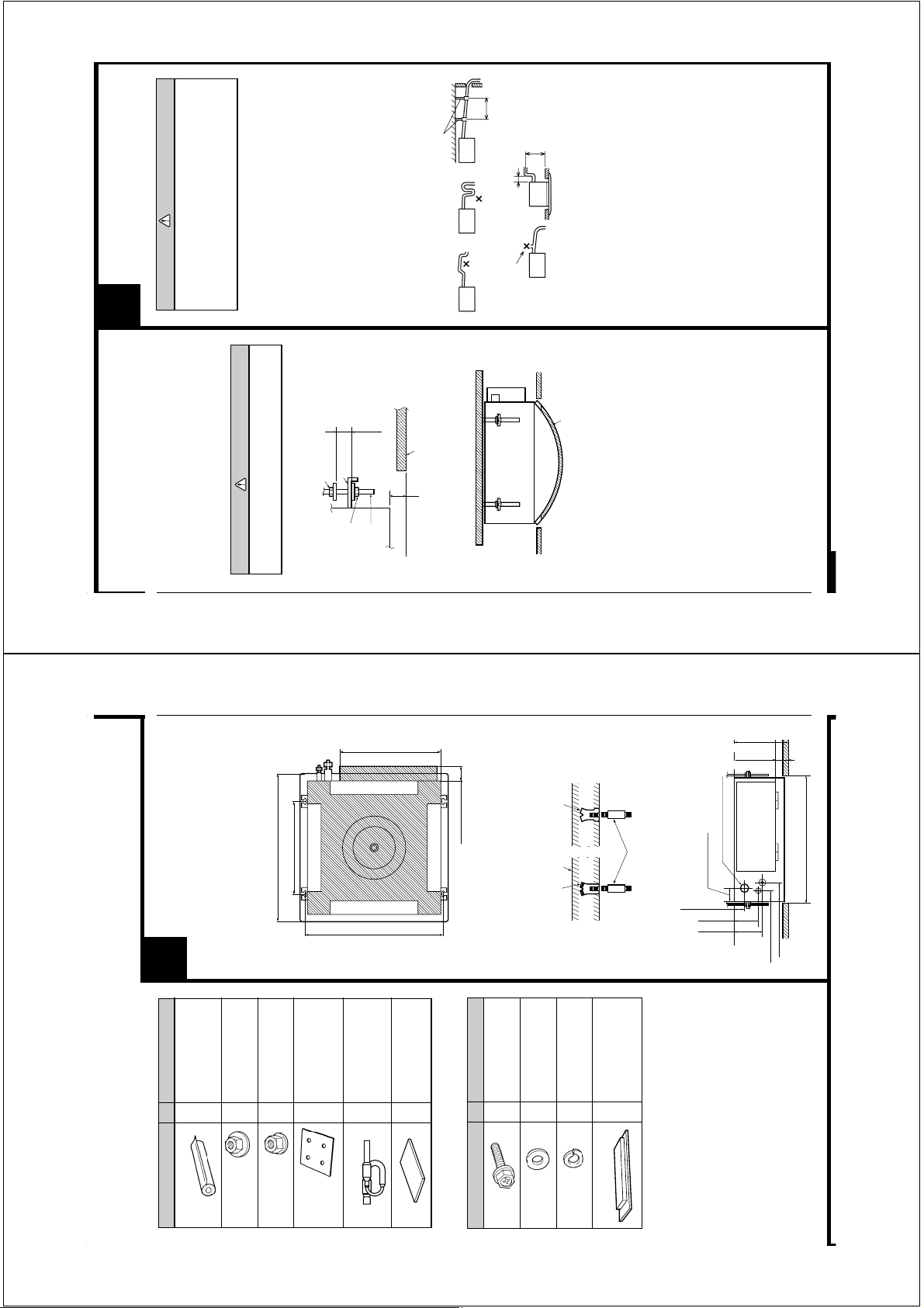
3. BODY INSTALLATION
between the special nuts (Fig. 6).
(1) Install special nut A, then special nut B onto the hanging bolt
(2) Raise the body and mount its hooks onto the hanging bolt
(3) Tur n special nut B to adjust the height of the body (Fig. 6).
to water leaks.
Using a level, or vinyl hose filled with water, fine adjust so
that the body is level.
(4) Leveling
and so there are no rises or traps in the pipe.
NOTE: Install the drain pipe.
• Install the drain pipe with downward gradient (1/50 to 1/100)
WARNING
Perform final tightening by tightening the double
nut firmly.
Rise
diameter 1-1/4" (32 mm)] and connect it with adhesive
(polyvinyl chloride) so that there is no leakage.
• Use general hard polyvinyl chloride pipe (VP25) [outside
Special nut A
Fig. 6
(400 mm) or less from the ceiling within a range of 6"
(150 mm) from the body. A rise dimension over this range will
• When the pipe is long, install supporters.
• Do not perform air bleeding.
After installing the body,
Hook
cause leakage.
• Always heat insulate the indoor side of the drain pipe.
• When desiring a high drain pipe height, raise it up to 15"
tighten the nuts.
Special nut B
Hanging bolt
Fig. 8
Ceiling
Fig. 7
Air bleeding
Vinyl hose
INDOOR UNIT
INSTALLATION
INSTALLATION PROCEDURE
Install the air conditioner as follows:
1
For indoor side pipe joint
2
15-3/4" (400 mm)
25-15/32" (650 mm)
(Hanging bolt position)
650 mm) (Grille measurement)
(
HANGING BOLTS
1. POSITION THE CEILING HOLE AND
Fig. 3
For installing indoor unit
For installing indoor unit
For ceiling hole cutting
4
4
1
1
17-5/16" (440 mm)
23-27/32" (606 mm)
(Hanging bolt position)
65 × 130 × T5
2
2-19/32" (66 mm)
2. HANGING PREPARATIONS
For mounting grille
Insert
Concrete
Hole-in anchor
Hole-in plug
Firmly fasten the hanging bolts as shown in Fig. 4 or by another
method.
Fig. 4
For mounting grille
For mounting grille
4
4
4
M10
Hanging bolt
For discharged air
2
Fig. 5
2-3/8" (60 mm)
"
(47 mm)
9-27/32" (250 mm)
2-1/8" (54 mm)
Drain pipe (I. D. ø32 mm)
1-27/32
4-3/8" (111 mm)
5-5/32"
(131 mm)
3-3/8" (86 mm)
1-27/32" (46 mm)
600 mm)
23-5/8" (
(Ceiling opening measurement)
STANDARD PARTS
Name and Shape Q’ty Application
The following installation parts are furnished. Use them as required.
Coupler heat insulation
INDOOR UNIT ACCESSORIES
Special nut A
(large flange)
Special nut B
(small flange)
Template
Indoor capillary tube
BR sheet
Name and Shape Q’ty Application
Bolt
GRILLE ACCESSORIES
Washer
Spring
washer
Blower cover insulation
Tape
Binder
Coupler heat
insulation
Be sure to overlap
the insulation
No gap
Coupler heat insulation
CAUTION
INSTALLING THE
Body
COUPLER HEAT INSULATION
Fig. 16
Table 4 : Flare nut tightening torque
Pipe Tightening torque
Small pipe
•m (150 to 200 kgf•cm)
•m (500 to 550 kgf•cm)
49.0 to 53.9 N
14.7 to 19.6 N
Large pipe
(6.35 mm dia.)
(12.7 mm dia.)
Tape
Fig. 17
CAUTION
TUBE
Be sure to connect the large pipe after
connecting the small pipe completely.
4. CONNECTING AN INDOOR CAPILLARY
and branch liquid pipe) as shown in Fig. 14.
Installation Procedure
(1) Braze each part (connection pipe, indoor capillary tube,
(2) Wrap the two BR sheets around the indoor capillary tube
After checking for gas leaks, insulate by wrapping insulation
around the two parts (large and small) of the indoor unit coupling,
4
Brazing (all around)
as shown in Fig. 15.
with insulation (Fig. 16) and affix the insulation with tape.
instruction sheet for the outdoor unit for details.
(3) Cover the indoor capillary tube and the branch liquid pipe
(4) Secure the insulation using the binders (Fig. 17).
• If the joint pipe must be installed, refer to the installation
Fig. 14
Indoor
unit side
using the coupler heat insulation.
Connection
pipe
Indoor capillary tube Indoor capillary tube
Connection
pipe
Fig. 18
Outdoor unit side
Branch liquid pipe
Fig. 15
BR sheet
Connection
pipe
Must fit tightly against body without any gap.
Indoor
capillary tube
Branch liquid pipe
Pipe
Cut line
Fig. 11
When bending the pipe, do
Cutter
Heat insulating
pipe
not bend it as is. The pipe will
be collapsed. In this case, cut
the heat insulating pipe with
a sharp cutter as shown in
Fig.11, and bend it after
exposing the pipe. After
bending the pipe as you
want, be sure to put the heat
insulating pipe back on the
pipe, and secure it with tape.
3. CONNECTION PIPES
Small pipe
Indoor unit
Fig. 12
CAUTION
CONNECTING THE PIPING
3
the units.
previous installations. Only use parts which
are delivered with the unit.
Prevent mineral oil from getting into the
system as this would reduce the lifetime of
1 Do not use mineral oil on flared part.
2 Never use piping which has been used for
nitrogen gas through them.
3 While welding the pipes, be sure to blow dry
Large pipe
CAUTION
threads will be damaged.
the indoor unit correctly. If the centering is
improper, the flare nut cannot be tightened
smoothly. If the flare nut is forced to turn, the
1 Be sure to apply the pipe against the port on
Table 3
is not deformed.
the pipe and remove the burrs.
unit and assemble as shown in (Table 3) and insert the
flare nut onto the pipe, and flare with a flaring tool.
1. FLARE PROCESSING
(1) Cut the connection pipe with pipe cutters so that the pipe
(2) Holding the pipe downwards so that cuttings cannot enter
that there are no cracks.
(3) Remove the flare nut from the indoor unit pipe and outdoor
(4) Check if the flared part “L” (Fig. 9) is spread uniformly and
2 Do not remove the flare nut from the indoor
Small (width across flats 17 mm)
Large (width across flats 24 mm)
Pipe Flare nut
Small pipe (6.35 mm dia.)
Large pipe (12.7 mm dia.)
90°
Holding spanner
Body side
unit pipe until immediately before connecting
the connection pipe.
When the flare nut is tightened properly by your hand, hold the
body side coupling with a separate spanner, then tighten with
a torque wrench (Fig. 13).
Fig. 13
L dimension
Small pipe (6.35 mm dia.)
1.4 to 1.7 mm
Large pipe (12.7 mm dia.)
1.9 to 2.2 mm
Width across flats
Fig. 9
2. BENDING PIPES
The pipes are shaped by your hands. Be careful not to collapse
them.
Fig. 10
Torque wrench
CAUTION
Hold the torque wrench at its grip, keeping it in
the right angle with the pipe as shown in Fig. 13,
in order to tighten the flare nut correctly.
NO
by unwinding it.
Extend the pipe
OK
Do not bend the pipes in an angle more than 90°.
When pipes are repeatedly bent or stretched, the material will
harden, making it difficult to bend or stretch them any more.
Do not bend or stretch the pipes more than three times.
 Loading...