

Page 1
R410A
INDOOR UNIT
1. CASSETTE
AU A36LATU
AU A45LATU
TYPE :
D2D_AU031E/01
2007.09.07
Page 2
1. FEATURE
MODEL :
CASSETTE TYPE
AU A36LATU / AO A36LATL
AU A36-45L
CASSETTE TYPE
AU A36-45L
AU A45LATU / AO A45LATL
FEATURES
Energy saving
High energy saving was realized by making the indoor unit and outdoor
unit fan motor and compressor all DC and optimal design of the refrigerant cycle. Rank A was achieved in European energy rank.
Easy maintenance
The control box is easily accessible for maintenance work.
Long-life filter
High efficiency, long-life filter extends the cleaning cycle.
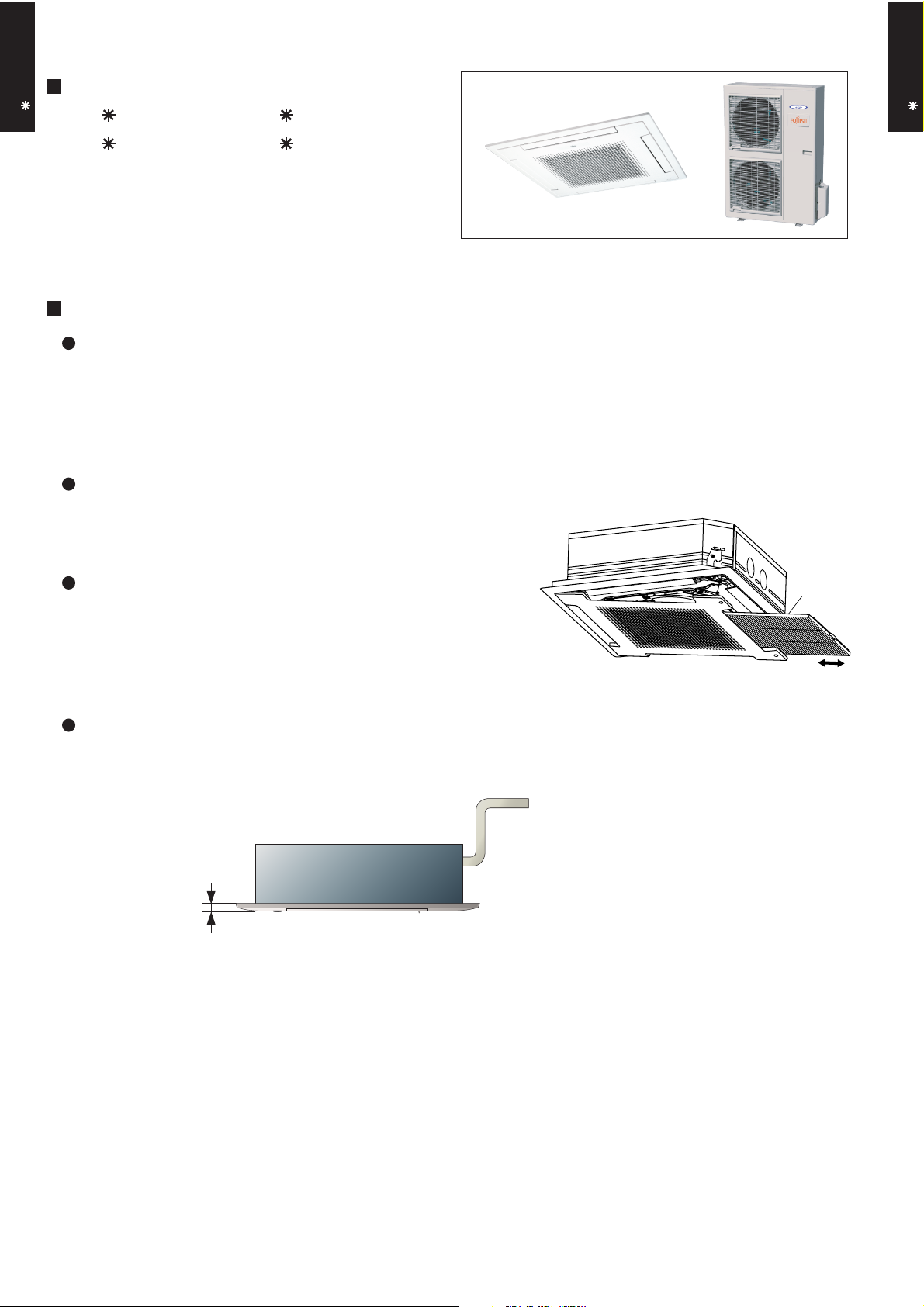
Slim intake grille
Slim type intake grille can fit the ceiling after installation.
30
(unit: mm)
Long-life
filter
- (01 - 01) -
Page 3
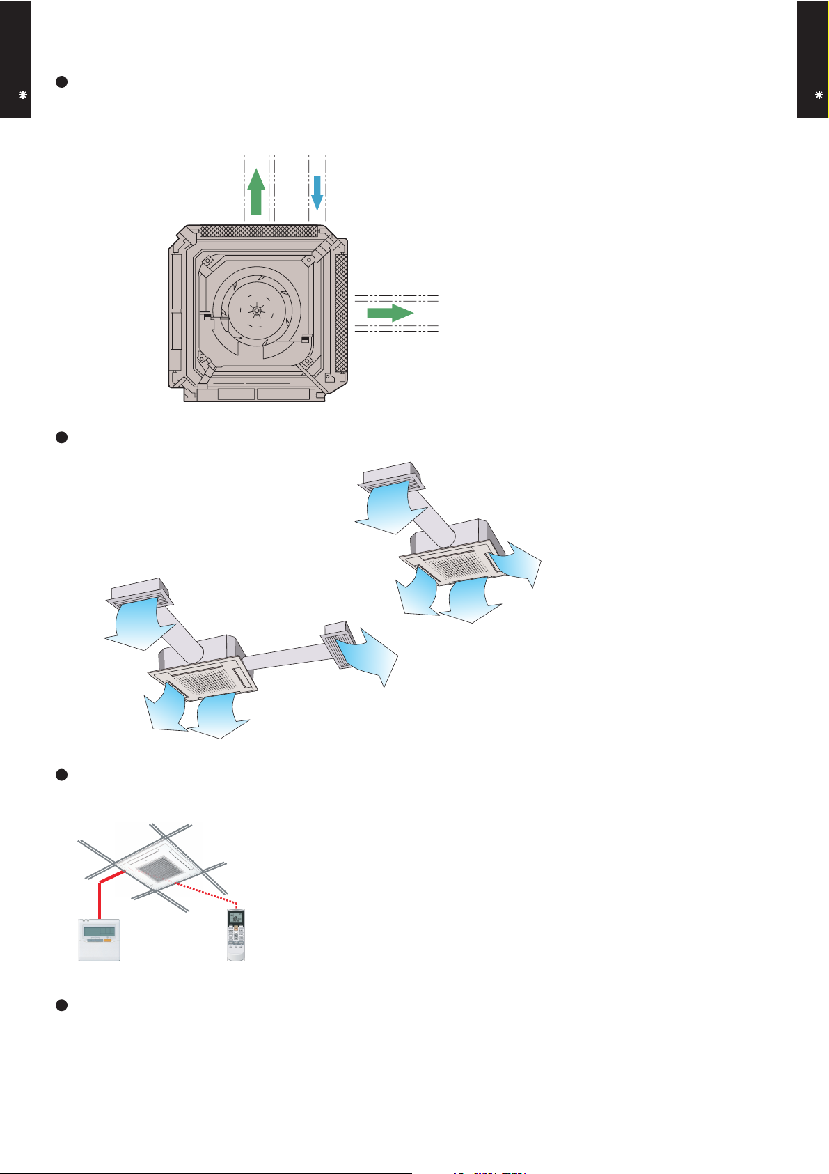
Duct connection hole opening
CASSETTE TYPE
AU A36-45L
Fresh air can be introduced through this opening.
Distribution
duct
Fresh air
Distribution
duct
CASSETTE TYPE
AU A36-45L
Conditioned air can be distributed by means of a distribution duct.
One-way
Two-way
EASY INSTALLATION
Easy setting by wireless or wired remote controller.
OTHER FUNCTIONS
• Setting the filter sign
The indoor unit has sign to inform the user that it is time to clean the filter
• Setting the cooler room temperature correction
• Setting the heater room temperature correction
• Auto restart
- (01 - 02) -
Page 4
2. REMOTE CONTROLLER
WIRED REMOTE CONTROLLER
CASSETTE TYPE
AU A36-45L
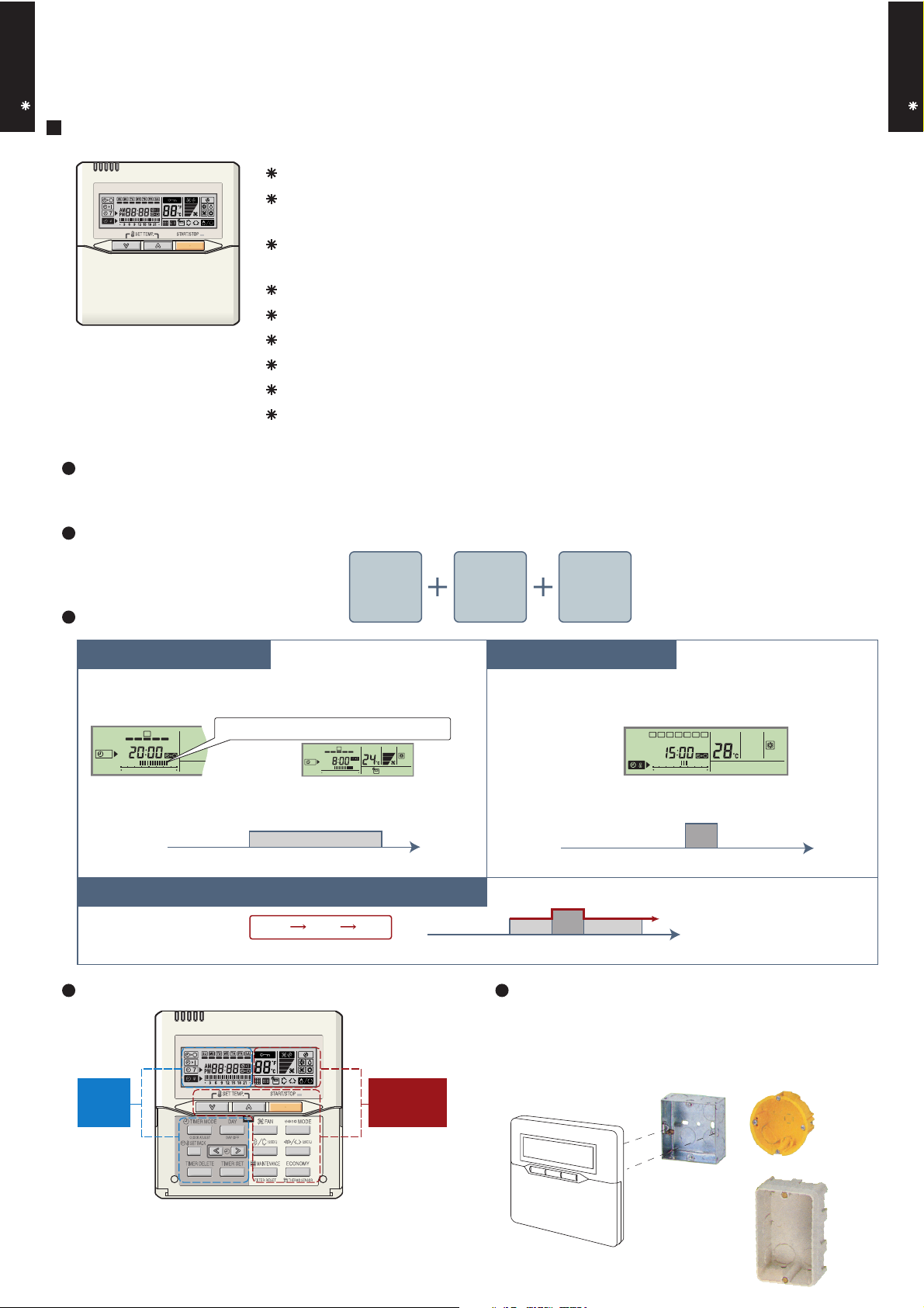
FEATURES
Various timer setup (ON / OFF / WEEKLY) are possible.
Equipped with weekly timer as standard function.
(2 times Start / Stop per day for a week)
When setting up a timer, operation mode and a temperature
setup can be changed.
When a failure occurs,the error code is displayed. (Maximum of 16)
Error indication.(A maximum of 16 error histories are memorizable.)
Up to 16 indoor units can be simultaneously controlled.
Economy operation are possible.
Easy installation with a slim shape with no bulge in the back.
The room temperature can be controlled by being detected the temperature
accurately with built-in thermo sensor.
Simple function setting
Setting of the air conditioner selection function is performed by remote controller.
CASSETTE TYPE
AU A36-45L
High performance and compact size
Three functions are combined in
one unit.
Wired
remote
controller
Built-in timers
Possible to set ON/OFF time to operate twice each day
of the week.
SUMOTUWETH FR SA
7
3126 9
15 18 21
Setup screen example
(Set to Wednesday: 8:00 to 20:00.)
0 3 6 9 12 15 18 21 Time
At "Weekly timer" + "Set back timer" setup
Easy-to-understand time bar display
SUMOTUWETH FR SA
7
3126 9
15 18 21
24°C
24°C 28°C 24°C
Screen
after setup
Weekly
timer
Setback
timer
Setback timerWeekly timer
Possible to set temperature for two time spans and
for each day of the week.
SUMOTUWETH FR SA
3126 9
15 18 21
Setup screen example
(Set from Sunday to Saturday: 12:00 to 15:00, 28 °C.)
28°C
0 3 6 9 12 15 18 21 Time
24°C
0 3 6 9 12 15 18 21 Time
28°C
Easy-to-understand operation Simple installation
Components are compatible with standard
switch boxes. Flat back construction allows
equipment to be installed wherever it is
needed.
Timer
area
[
Variable timer control
]
The operation/display sections are zoned according to time and operation, enabling variable programming to match application.
Operation
area
European
switch box
- (01 - 03) -
JIS box
Page 5
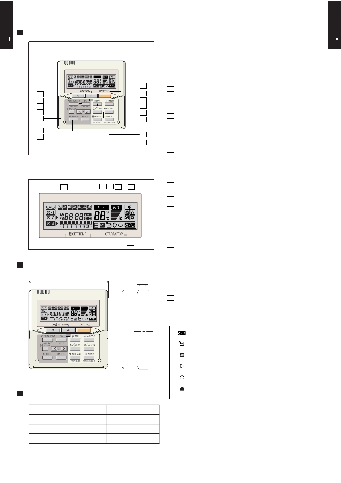
FUNCTIONS
CASSETTE TYPE
AU A36-45L
15
2
6
7
8
9
10
11
1
3
4
13
12
5
14
Display panel
19
20
16
18
17
1
START/STOP button
Pressed to start and stop operation.
2
Set temperature button
Selects the setting temperature.
3
Master control button
Selects the operating mode(AUTO, HEAT, FAN, COOL, DRY).
4
Fan control button
Selects the fan speed (AUTO, QUIET, LOW, MED, HIGH).
5
Economy button
Turns the economy efficient mode on and off.
6
Timer mode (CLOCK ADJUST) button
Selects the timer mode (OFF TIMER, ON TIMER, WEEKLY TIMER).
Set the current time.
7
Day (DAY OFF) button
Temporarily cancels of one day timer.
8
Set back button
Pressed to select the set back timer.
9
Set time button
Pressed to set time.
10
Delete button
The schedule of a weekly timer is deleted.
11
Set button
Sets the date, hour, minute and on-off time.
12
Vertical airflow direction and swing button
Push for two seconds to change the swing mode.
13
Horizontal airflow direction and swing button*
Push for two seconds to change the swing mode.
CASSETTE TYPE
AU A36-45L
DIMENSION
120
Front View
SPECIFICATION
21
[ Unit : mm ]
120
14
Filter button
15
Operation lamp
Lights during operation and when the timer is on.
16
Timer and clock display
17
17
Operation mode display
18
Fan speed display
19
Operation lock display
20
Temperature display
21
Function display
Defrost display
Thermo sensor display
Economy display
Vertical swing display
Horizontal swing display*
Filter display
SIZE (H x W x D mm) 120 x 120 x 17
WEIGHT ( g ) 160
CABLE LENGTH ( m )
POWER ( V )
10
12
*These functions are not available.
- (01 - 04) -
Page 6
3. SPECIFICATIONS
AU A36LATU AU A45LATU
252 × 970 × 39.9
× 2 pieces
252 × 970 × 39.9
× 2 pieces
Pipe type Copper Copper
9.52 ( 3 / 8 in.) 9.52 ( 3 / 8 in.)
15.88 ( 5 / 8 in.) 15.88 ( 5 / 8 in.)
Outer diameter : 37.0 / Inner diameter : 32.0
WIRED
ABS
White
296 × 830 × 830
455 × 1060 × 1025
ABS
Turbo × 1
Sound pressure level
Cooling
dB(A)
Heating
Fan
Heating
Airflow
rate
m3/h
Type × Q'ty
mm
Heat exchanger type
Cooling
Enclosure (Panel)
Dimensions
( H × W × D)
Operation range
Cooling
kg(lb.)
Size
mm
Connection pipe
Weight
Remote controller type
Drain pipe
Material
Size
kW/kW
Moisture removal
Cooling
Heating
Current
Cooling
A
Heating
Rated
Rated
Input power
Cooling
kW
Heating
Rated
Available voltage range
Capacity
Cooling
Heating
Type
Model name
mm
Rated
Min.- Max.
Rated
Min.- Max.
Rated
Power source
INVERTER HEATPUMP
CASSETTE MODEL
230V 50Hz
198-264V 50Hz
CASSETTE TYPE
AU A36-45L
European energy label Cooling A A
*Max. 4.33 4.56
*Max. 4.33 4.56
*Max. 19.0 20.0
*Max. 19.0 20.0
EER 3.21 3.21
COP 3.71 3.71
Heating A A
kW 10.00 12.50
BTU/h 34100 42700
kW 3.80 - 11.20 4.00 - 14.00
BTU/h 13000 - 38200 13700 - 47800
kW 11.20 14.00
BTU/h 38200 47800
kW 4.00 - 14.00 4.20 - 16.20
BTU/h 13700 - 47800 14300 - 55300
3.11 3.89
3.02 3.77
13.6 17.0
13.2 16.5
l/h (pints/h) 3.5 ( 6.2 ) 4.5 ( 7.9 )
High 1650 1750
Med 1370 1430
Low 1140 1200
Quiet 930 1030
High 1650 1750
Med 1370 1430
Low 1140 1200
Quiet 990 1030
CASSETTE TYPE
AU A36-45L
Motor output W 116 116
High 50 52
Med 46 47
Low 41 42
Quiet 36 39
High 50 52
Med 46 47
Low 41 42
Quiet 37 39
Dimensions (H × W × D)
Fin pitch 1.4 1.4
Rows x Stages 3 × 12 3 × 12
Fin type Aluminium Aluminium
Material
Colour
Net
Gross
Net 39 (86) 39 (86)
Gross 54 (119) 54 (119)
Liquid
Gas
Method Flare Flare
°C 18 to 32 18 to 32
%RH 80 or less 80 or less
Heating °C 30 or less 30 or less
Note :
Specifications are based on the following conditions.
Cooling : Indoor temperature of 27 °CDB / 19 °CWB.and outdoor temperature of 35 °CDB/24 °CWB.
Heating : Indoor temperature of 20 °CDB / 15 °CWB.and outdoor temperature of 7 °CDB/6 °CWB.
Pipe length : 7.5 m, Height difference : 0 m.(Outdoor unit - Indoor unit)
The maximum current and the maximum input value are the maximum values when operated within the operation range (temperature).
mm
- (01 - 05) -
Page 7
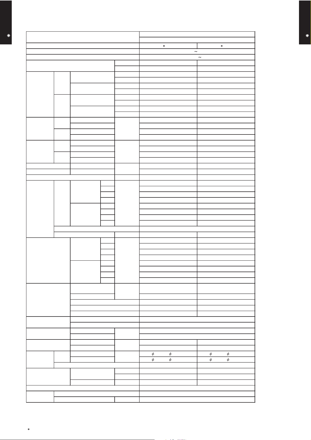
4. DIMENSIONS
MODEL : AU A36L, AU A45L
CASSETTE TYPE
AU A36-45L
(Unit : mm)
CASSETTE TYPE
AU A36-45L
SELECTION OF SETTING
- (01 - 06) -
Page 8
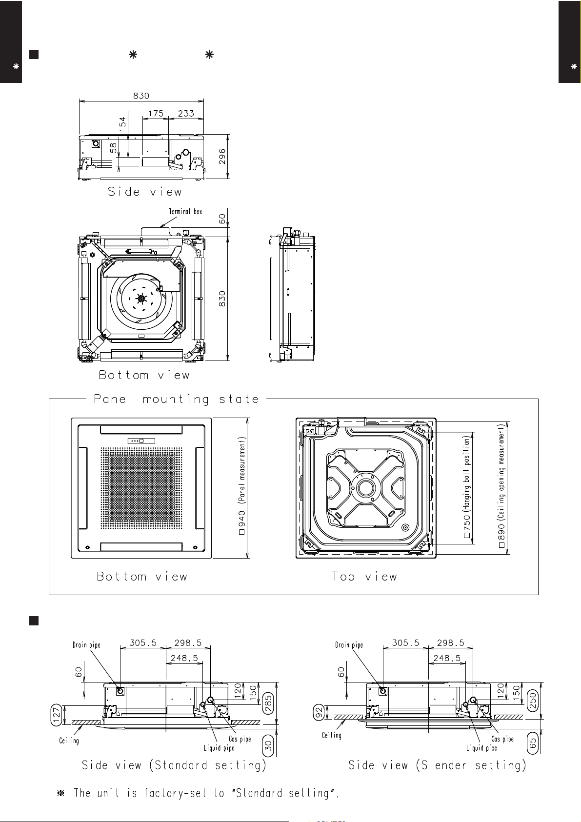
MOUNTING POSITION
Floor
CASSETTE TYPE
AU A36-45L
Strong and durable ceiling
(Unit : mm)
CASSETTE TYPE
AU A36-45L
Ceiling mode “Standard”: 2,300 - 3,000
Ceiling mode “High” : 3,000 - 4,200
You can select 2-way setting
(A) Standard setting (B) Slender setting
300 mm
or more
100 or more 100 or more
1,000
or more
Obstruction
265 mm
or more
1,000
or more
100 or more
(4 directions) (3 directions)
Piping position
(2 directions) (2 directions)
100 or more
- (01 - 07) -
Page 9
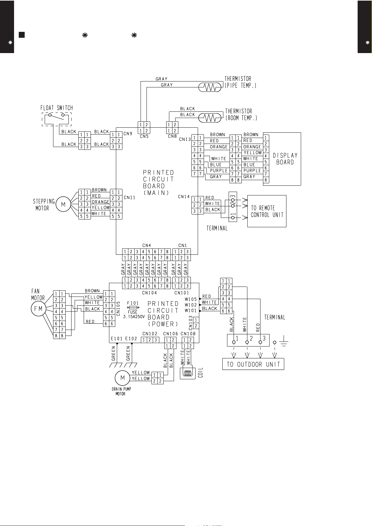
5. WIRING DIAGRAMS
MODEL : AU A36L, AU A45L
CASSETTE TYPE
AU A36-45L
CASSETTE TYPE
AU A36-45L
- (01 - 08) -
Page 10
6. CAPACITY TABLE
AFR
Indoor temperature
18212325272932
27.2
12151618192123
Outdoor temperature
°CDB
-15
-1005101520253035
40
46
Outdoor temperature
°CDB
-15
-1005
10
21
2346121516
15
20
25
30
35
40
18
19
28.8
AFR
Indoor temperature
18212325272932
6-1. COOLING CAPACITY
CASSETTE TYPE
AU A36-45L
This table is created using the maximum capacity.
MODEL : AU A36L
°CDB
°CWB
TC SHC PI TC SHC PI TC SHC PI TC SHC PI TC SHC PI TC SHC PI TC SHC PI
9.86 7.28 1.17 10.98 7.32 1.19 11.35 7.96 1.19 12.10 7.99 1.20 12.48 8.63 1.21 13.23 8.59 1.22 13.97 9.15 1.23
9.52 7.11 1.41 10.61 7.16 1.43 10.97 7.78 1.44 11.69 7.80 1.45 12.05 8.43 1.46 12.78 8.39 1.48 13.50 8.94 1.49
9.67 7.19 1.27 10.78 7.23 1.29 11.14 7.86 1.29 11.88 7.89 1.31 12.25 8.52 1.31 12.98 8.48 1.33 13.72 9.04 1.34
9.32 7.02 1.50 10.38 7.06 1.53 10.74 7.67 1.53 11.45 7.70 1.55 11.80 8.31 1.56 12.51 8.28 1.57 13.22 8.82 1.59
9.35 7.03 1.46 10.41 7.07 1.48 10.77 7.69 1.49 11.48 7.71 1.50 11.83 8.33 1.51 12.54 8.29 1.53 13.25 8.84 1.54
8.96 6.84 1.70 9.98 6.88 1.72 10.33 7.48 1.73 11.01 7.50 1.75 11.35 8.10 1.76 12.03 8.07 1.78 12.71 8.60 1.79
10.93 7.82 2.55 12.18 7.87 2.59 12.59 8.56 2.60 13.42 8.58 2.63 13.84 9.27 2.64 14.67 9.23 2.67 15.50 9.84 2.70
10.79 7.75 2.65 12.01 7.80 2.69 12.42 8.48 2.71 13.24 8.51 2.73 13.65 9.19 2.75 14.47 9.15 2.77 15.29 9.75 2.80
10.28 7.49 2.96 11.45 7.54 3.01 11.84 8.19 3.02 12.62 8.22 3.05 13.01 8.88 3.07 13.80 8.84 3.10 14.58 9.42 3.13
8.85 6.20 3.37 9.86 6.23 3.42 10.19 6.78 3.44 10.86 6.80 3.47 11.20 7.34 3.49 11.87 7.31 3.52 12.54 7.79 3.56
7.97 6.36 2.82 8.88 6.40 2.87 9.18 6.96 2.88 9.78 6.98 2.91 10.09 7.54 2.93 10.69 7.51 2.96 11.30 8.00 2.99
5.60 5.28 2.20 6.23 5.31 2.24 6.45 5.77 2.25 6.87 5.79 2.27 7.08 6.25 2.28 7.51 6.23 2.31 7.93 6.63 2.33
CASSETTE TYPE
AU A36-45L
MODEL : AU A45L
°CDB
°CWB
TC SHC PI TC SHC PI TC SHC PI TC SHC PI TC SHC PI TC SHC PI TC SHC PI
10.81 8.39 1.43 12.05 8.44 1.45 12.46 9.18 1.46 13.28 9.21 1.48 13.69 9.94 1.48 14.51 9.91 1.50 15.33 10.55 1.51
10.44 8.19 1.72 11.63 8.24 1.75 12.03 8.96 1.76 12.82 8.99 1.77 13.22 9.71 1.78 14.01 9.67 1.80 14.80 10.30 1.82
10.62 8.30 1.55 11.83 8.35 1.57 12.23 9.07 1.58 13.04 9.10 1.60 13.44 9.83 1.61 14.25 9.79 1.62 15.05 10.43 1.64
10.23 8.08 1.83 11.39 8.13 1.86 11.78 8.84 1.87 12.56 8.86 1.89 12.95 9.57 1.90 13.72 9.53 1.92 14.50 10.16 1.93
10.26 8.10 1.77 11.43 8.15 1.80 11.82 8.86 1.81 12.60 8.88 1.83 12.99 9.59 1.84 13.77 9.56 1.86 14.55 10.18 1.87
9.84 7.87 2.05 10.96 7.92 2.09 11.33 8.61 2.10 12.08 8.64 2.12 12.46 9.33 2.13 13.20 9.29 2.15 13.95 9.90 2.17
12.05 9.07 3.08 13.43 9.12 3.13 13.88 9.92 3.14 14.80 9.95 3.18 15.26 10.74 3.19 16.17 10.70 3.22 17.09 11.40 3.26
11.89 8.99 3.20 13.24 9.04 3.25 13.70 9.83 3.27 14.60 9.86 3.30 15.05 10.65 3.32 15.95 10.60 3.35 16.86 11.30 3.39
11.33 8.68 3.58 12.62 8.73 3.64 13.05 9.49 3.66 13.91 9.52 3.70 14.34 10.28 3.71 15.20 10.24 3.75 16.06 10.91 3.79
11.06 8.53 4.21 12.32 8.58 4.27 12.74 9.33 4.29 13.58 9.36 4.34 14.00 10.11 4.36 14.84 10.07 4.40 15.68 10.73 4.45
8.74 7.30 3.41 9.74 7.34 3.47 10.07 7.98 3.48 10.73 8.01 3.52 11.06 8.65 3.54 11.73 8.62 3.57 12.39 9.18 3.61
6.11 5.98 2.67 6.81 6.02 2.71 7.04 6.54 2.72 7.50 6.56 2.75 7.74 7.08 2.76 8.20 7.06 2.79 8.66 7.52 2.79
AFR : Air flow rate(m3/min)
TC : Total capacity (kW)
SHC : Sensible Heat capacity (kW)
PI : Power Input (kW)
- (01 - 09) -
Page 11
6-2. HEATING CAPACITY
°CDB
Outdoor temperature
Indoor temperature
°CDB
°CWB
-15
-16
-10
-11
-5
-716151020
15
7610
8
0
182022
24
AFR
27.2
AFR
28.8
2418°CDB
-253
Indoor temperature
1618202224
Outdoor temperature
°CDB
°CWB
-15
-16
-10
-11-5-70-2
537
6
108151020
15
24
18
CASSETTE TYPE
AU A36-45L
This table is created using the maximum capacity.
MODEL : AU A36L
TC PI TC PI TC PI TC PI TC PI
9.97 3.60 9.73 3.67 9.50 3.75 9.26 3.82 9.02 3.90
10.89 3.61 10.64 3.68 10.38 3.76 10.12 3.83 9.86 3.91
11.64 3.58 11.36 3.65 11.08 3.73 10.81 3.80 10.53 3.87
12.66 3.61 12.36 3.69 12.06 3.77 11.76 3.84 11.46 3.92
13.88 3.61 13.55 3.69 13.22 3.76 12.89 3.84 12.56 3.91
14.70 3.62 14.35 3.69 14.00 3.77 13.65 3.85 13.30 3.92
15.14 3.58 14.78 3.66 14.42 3.73 14.06 3.81 13.70 3.88
14.64 3.19 14.29 3.25 13.94 3.32 13.59 3.39 13.24 3.45
CASSETTE TYPE
AU A36-45L
MODEL : AU A45L
14.20 2.81 13.86 2.87 13.52 2.93 13.18 2.98 12.84 3.04
14.87 2.80 14.52 2.86 14.16 2.92 13.81 2.98 13.45 3.03
TC PI TC PI TC PI TC PI TC PI
11.72 4.23 11.44 4.32 11.16 4.41 10.88 4.50 10.60 4.54
12.73 4.25 12.43 4.34 12.13 4.43 11.82 4.52 11.52 4.56
13.59 4.23 13.27 4.32 12.94 4.40 12.62 4.49 12.30 4.54
14.61 4.17 14.26 4.26 13.91 4.35 13.56 4.43 13.22 4.52
16.04 4.18 15.66 4.27 15.28 4.35 14.90 4.44 14.52 4.53
17.01 4.20 16.60 4.28 16.20 4.37 15.79 4.46 15.39 4.55
17.53 4.16 17.11 4.25 16.70 4.33 16.28 4.42 15.86 4.51
AFR : Air flow rate(m3/min)
TC : Total capacity (kW)
PI : Power Input (kW)
16.18 3.41 15.80 3.49 15.41 3.56 15.03 3.63 14.64 3.70
15.81 3.05 15.44 3.12 15.06 3.18 14.68 3.24 14.31 3.31
16.56 3.04 16.17 3.10 15.77 3.17 15.38 3.23 14.99 3.29
- (01 - 10) -
Page 12

7. FAN PERFORMANCE
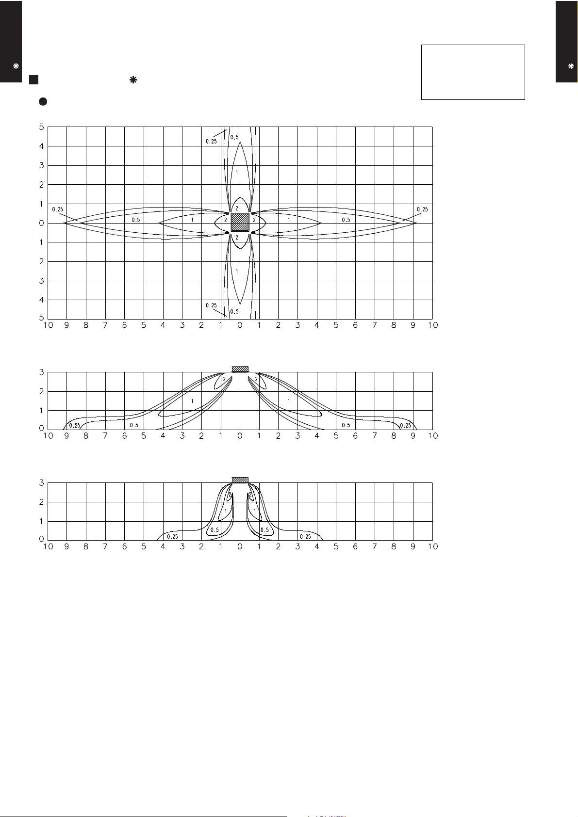
7-1. AIR VELOCITY DISTRIBUTION
CASSETTE TYPE
AU A36-45L
MODEL : AU A36L
4-WAY AIR OUTLET
(m)
Unit : m/s
Note :
Condition
Fan speed : High
Operation mode : FAN
Ceiling mode : Standard
TOP VIEW
HORIZONTAL LOUVER
: Upward
(m)
CASSETTE TYPE
AU A36-45L
(m)
(m)
Unit : m/s
SIDE VIEW
HORIZONTAL LOUVER
: Upward
(m)
Unit : m/s
SIDE VIEW
HORIZONTAL LOUVER
: Downward
(m)
- (01 - 11) -
Page 13
Note :
Condition
CASSETTE TYPE
AU A36-45L
MODEL : AU A45L
Fan speed : High
Operation mode : FAN
Ceiling mode : Standard
CASSETTE TYPE
AU A36-45L
4-WAY AIR OUTLET
(m)
Unit : m/s
TOP VIEW
HORIZONTAL LOUVER
: Upward
(m)
(m)
(m)
Unit : m/s
SIDE VIEW
HORIZONTAL LOUVER
: Upward
(m)
Unit : m/s
SIDE VIEW
HORIZONTAL LOUVER
: Downward
(m)
- (01 - 12) -
Page 14

Note :
Condition
CASSETTE TYPE
AU A36-45L
MODEL : AU A36L, AU A45L
Fan speed : High
Operation mode : FAN
Ceiling mode : Standard
CASSETTE TYPE
AU A36-45L
3-WAY AIR OUTLET
(m)
Unit : m/s
TOP VIEW
HORIZONTAL LOUVER
: Upward
(m)
(m)
(m)
Unit : m/s
SIDE VIEW
HORIZONTAL LOUVER
: Upward
(m)
Unit : m/s
SIDE VIEW
HORIZONTAL LOUVER
: Downward
(m)
- (01 - 13) -
Page 15

Note :
Condition
CASSETTE TYPE
AU A36-45L
MODEL : AU A36L, AU A45L
Fan speed : High
Operation mode : FAN
Ceiling mode : Standard
CASSETTE TYPE
AU A36-45L
2-WAY AIR OUTLET
(m)
Unit : m/s
TOP VIEW
HORIZONTAL LOUVER
: Upward
(m)
(m)
(m)
Unit : m/s
SIDE VIEW
HORIZONTAL LOUVER
: Upward
(m)
Unit : m/s
SIDE VIEW
HORIZONTAL LOUVER
: Downward
(m)
- (01 - 14) -
Page 16

7-2. AIR FLOW
m3/h
1650
m3/h
1370
m3/h
1140
m3/h
930
m3/h
1650
m3/h
1370
m3/h
990
420
480
400
Air flow
(r.p.m)
Number of
rotations
(r.p.m)
HIGH
LOW
QUIET
680
570
680
MED
570
LOW
480
QUIET
7-2-1. STANDARD CEILING MODE
CASSETTE TYPE
AU A36-45L
MODEL : AU A36L
COOLING
Fan speed
l/s 458
CFM 971
CASSETTE TYPE
AU A36-45L
MED
HEATING
HIGH
Number of
rotations
l/s 381
CFM 806
l/s 317
CFM 671
l/s 258
CFM 547
Air flowFan speed
l/s 458
CFM 971
l/s 381
CFM 806
m3/h
l/s 317
CFM 671
l/s 275
CFM 583
- (01 - 15) -
1140
Page 17

CASSETTE TYPE
m3/h
1750
m3/h
1430
m3/h
1200
m3/h
1030
m3/h
1750
m3/h
1430
m3/h
1200
m3/h
1030
720
MED
590
LOW
500
QUIET
440
(r.p.m)
720
MED
590
LOW
QUIET
500
440
(r.p.m)
AU A36-45L
MODEL : AU A45L
CASSETTE TYPE
AU A36-45L
COOLING
Number of
rotations
Air flowFan speed
HIGH
HEATING
Number of
rotations
l/s 486
CFM 1030
l/s 397
CFM 842
l/s 333
CFM 706
l/s 286
CFM 606
Air flowFan speed
HIGH
l/s 486
CFM 1030
l/s 397
CFM 842
l/s 333
CFM 706
l/s 286
CFM 606
- (01 - 16) -
Page 18

7-2-2. HIGH CEILING MODE
m3/h
1750
m3/h
1500
m3/h
1270
m3/h
1060
m3/h
1750
m3/h
1500
m3/h
1270
m3/h
1110
720
MED
620
LOW
530
QUIET
470
(r.p.m)
720
620
530
450
MED
LOW
QUIET
(r.p.m)
CASSETTE TYPE
AU A36-45L
MODEL : AU A36L
COOLING
Number of
rotations
CASSETTE TYPE
AU A36-45L
Air flowFan speed
HIGH
HEATING
Number of
rotations
l/s 486
CFM 1030
l/s 417
CFM 883
l/s 353
CFM 747
l/s 294
CFM 624
Air flowFan speed
HIGH
l/s 486
CFM 1030
l/s 417
CFM 883
l/s 353
CFM 747
l/s 308
CFM 653
- (01 - 17) -
Page 19

CASSETTE TYPE
m3/h
1750
m3/h
1550
m3/h
1320
m3/h
1160
m3/h
1750
m3/h
1550
m3/h
1160
HIGH
720
LOW
QUIET
640
550
490
(r.p.m)
720
640
550
490
MED
LOW
QUIET
(r.p.m)
AU A36-45L
MODEL : AU A45L
CASSETTE TYPE
AU A36-45L
COOLING
Number of
rotations
Air flowFan speed
HIGH
HEATING
Number of
rotations
l/s 486
CFM 1030
l/s 431
CFM 912
l/s 367
CFM 777
l/s 322
CFM 683
Air flowFan speed
MED
l/s 486
CFM 1030
l/s 431
CFM 912
m3/h
1320
l/s 367
CFM 777
l/s 322
CFM 683
- (01 - 18) -
Page 20
7-2-3. 3-WAY OUTLET MODE
m3/h
1470
m3/h
1400
m3/h
1340
m3/h
1300
m3/h
1430
m3/h
1360
m3/h
1300
720
MED
700
LOW
QUIET
670
640
(r.p.m)
MED
720
690
LOW
660
QUIET
640
(r.p.m)
CASSETTE TYPE
AU A36-45L
MODEL : AU A36L
COOLING / HEATING
Number of
rotations
CASSETTE TYPE
AU A36-45L
Air flowFan speed
HIGH
MODEL : AU A45L
COOLING / HEATING
Number of
rotations
l/s 408
CFM 865
l/s 389
CFM 824
l/s 372
CFM 789
l/s 361
CFM 765
Air flowFan speed
HIGH
m3/h
l/s 408
CFM 865
l/s 397
CFM 842
l/s 378
CFM 800
l/s 361
CFM 765
- (01 - 19) -
1470
Page 21

7-2-4. 2-WAY OUTLET MODE
m3/h
1120
m3/h
1070
m3/h
1020
m3/h
990
m3/h
1120
m3/h
1090
m3/h
1040
m3/h
990
720
700
670
640
MED
LOW
QUIET
(r.p.m)
HIGH
720
MED
690
660
QUIET
640
(r.p.m)
CASSETTE TYPE
AU A36-45L
MODEL : AU A36L
COOLING / HEATING
Number of
rotations
Air flowFan speed
l/s 311
CFM 659
l/s 297
CFM 630
CASSETTE TYPE
AU A36-45L
LOW
MODEL : AU A45L
COOLING / HEATING
Number of
rotations
HIGH
l/s 283
CFM 600
l/s 275
CFM 583
Air flowFan speed
l/s 311
CFM 659
l/s 303
CFM 641
l/s 289
CFM 612
l/s 275
CFM 583
- (01 - 20) -
Page 22

7-3. DUCT CONNECTION
CASSETTE TYPE
AU A36-45L
MODEL : AU A36L, AU A45L
OUTLET AIR
CASSETTE TYPE
AU A36-45L
Duct
(Inside Dia. ø100mm)
L
Duct
(Inside Dia. ø100mm)
L
DUCT
STATIC
PRESSURE
DUCT
STATIC
PRESSURE
(Pa)
(Pa)
98
L=5m
L=3m
L=1m
49
0
01234
98
(m
3
/min)
L=5m
49
(mmAq)
10
8
6
4
2
0
5
(mmAq)
10
L=3m
8
L=1m
6
4
2
FRESH AIR
Duct
(Inside Dia. ø70mm)
P
Static pressure required
to take in fresh air
Duct Fan
(Pa)
DUCT
STATIC
PRESSURE
0
0 1234
(m3/min)
(mmAq)
7
58.8
6
5
39.2
4
3
19.6
2
1
0
0
0.1 0.2 0.3 0.4 0.5 0.6
0
(m3/min)
0
5
- (01 - 21) -
Page 23

8. OPERATION NOISE
HIGH
HIGH
HIGH
HIGH
QUIET
QUIET
QUIET
QUIET
8-1. NOISE LEVEL CURVE
CASSETTE TYPE
AU A36-45L
COOLING
MODEL : AU A36L
80
70
60
50
40
30
20
Octave band sound pressure level, dB:(0dB=0.0002µbar)
10
NC-65
NC-60
NC-55
NC-50
NC-45
NC-40
NC-35
NC-30
NC-25
NC-20
NC-15
MODEL : AU A45L
80
70
60
50
40
30
20
Octave band sound pressure level, dB:(0dB=0.0002µbar)
10
Condition
Ceiling mode : Standard
Air outlet : 4-way air outlet
NC-65
NC-60
NC-55
NC-50
NC-45
NC-40
NC-35
NC-30
NC-25
NC-20
NC-15
CASSETTE TYPE
AU A36-45L
0
63 125 250 500 1,000 2,000 4,000 8,000
Octave band center frequency,Hz
HEATING
MODEL : AU A36L
80
70
60
50
40
30
20
Octave band sound pressure level, dB:(0dB=0.0002µbar)
10
NC-65
NC-60
NC-55
NC-50
NC-45
NC-40
NC-35
NC-30
NC-25
NC-20
NC-15
0
63 125 250 500 1,000 2,000 4,000 8,000
Octave band center frequency,Hz
MODEL : AU A45L
80
70
60
50
40
30
20
Octave band sound pressure level, dB:(0dB=0.0002µbar)
10
NC-65
NC-60
NC-55
NC-50
NC-45
NC-40
NC-35
NC-30
NC-25
NC-20
NC-15
0
63 125 250 500 1,000 2,000 4,000 8,000
Octave band center frequency,Hz
- (01 - 22) -
0
63 125 250 500 1,000 2,000 4,000 8,000
Octave band center frequency,Hz
Page 24

8-2. SOUND LEVEL CHECK POINT
CASSETTE TYPE
AU A36-45L
// //
CENTER
Microphone
CASSETTE TYPE
AU A36-45L
1.5m
Microphone
// //
CENTER
- (01 - 23) -
Page 25

9. ELECTRIC CHARACTERISTICS
AU A36L AU A45L
mm
2
1.5-2.5
51
Wiring spec.
(Indoor unit to outdoor unit)
Power supply
230500.7
CASSETTE TYPE
AU A36-45L
Model name
Voltage V
Frequency Hz
Max. operating current (Indoor unit) A
Connection cable
Limited wiring length m
CASSETTE TYPE
AU A36-45L
- (01 - 24) -
Page 26

10. SAFETY DEVICES
139±15°C OFF
109±19°C ON
Protection form
3.15A 250V
Model
CASSETTE TYPE
AU A36-45L
Circuit protection Current fuse (PCB)
Fan motor protection Thermal protection program
AU A36L AU A45L
CASSETTE TYPE
AU A36-45L
- (01 - 25) -
Page 27

11. OPTIONAL PARTS
CASSETTE TYPE
AU A36-45L
Exterior Summary
Parts name
Model No.
CASSETTE TYPE
AU A36-45L
Wireless remote
controller
Additional
grille
UTB- NA
UTG-AGEA-W
Unit control is performed by
wireless remote controller
The additional grille hides the
gap between the ceiling hole
and the outlet grille
- (01 - 26) -
Page 28

R410A
OUTDOOR UNIT
2.
SINGLE TYPE :
AO A36LATL
AO A45LATL
D2D_AO009E/02
2007.09.07
Page 29

1. SPECIFICATIONS
AO A36LATL AO A45LATL
1260 × 900 × 36.4
1260 × 900 × 36.4
Colour
Net
Gross
Motor output
Type
Charge
Type
Material
Motor output
Cooling
Heating
Dimensions (H × W × D)
Type
Model name
Power source
Available voltage range
1290 × 900 × 330
98 (216)
107 (236)
15.88 ( 5/8 in.)
Flare
-15 to 46
-15 to 24
1430 × 1050 × 445
9.52 ( 3/8 in.)
Copper
Aluminium
Steel sheet
Beige (10YR7.5/1.0NN)
Twin Rotary × 1
3750
R410A
POE
3350
INVERTER HEATPUMP
230V 50Hz
198-264V 50Hz
Propeller × 2
m
Connection pipe
Size
mm
Liquid
Gas
Method
Max. length
Max. height difference
Compressor
Refrigerant
Sound pressure level
Starting current
Cooling
Heating
Type × Q'ty
Refrigerant oil
Enclosure
Heat exchanger type
Fin pitch
Rows x Stages
Pipe type
Fin type
Type × Q'ty
mm
Weight
kg(lb.)
Dimensions
(H × W × D)
Net
Gross
°C
Operation range
Fan
Airflow
rate
m3/h
dB(A)
mm
Cooling
Heating
OUTDOOR UNIT
AO A36-45L
A 15.0 15.0
6600 6600
6600 6600
W 103 × 2 103 × 2
54 55
55 56
1.30 1.30
2 × 60 2 × 60
W
OUTDOOR UNIT
AO A36-45L
g
50 (chargeless : 20) 50 (chargeless : 20)
30 30
Note :
Specifications are based on the following conditions.
Cooling : Indoor temperature of 27°CDB/19°CWB. and outdoor temperature of 35°CDB/24°CWB.
Heating : Indoor temperature of 20°CDB/15°CWB. and outdoor temperature of 7°CDB/6°CWB.
Pipe length : 7.5 m, Height difference : 0 m. (Outdoor unit - Indoor unit)
- (02 - 01) -
Page 30

2. DIMENSIONS
MODEL : AO A36L, AO A45L
(Unit : mm)
Top view
OUTDOOR UNIT
AO A36-45L
1290
900
77 31
12330
OUTDOOR UNIT
AO A36-45L
21
370
Drain cap
mounting places
MOUNTING POSITION
When there are
obstacles at the
back or front side.
When there are obstacles
at the back and front sides.
9
Front view
650
Air flow
Bottom view
400
Side view
4-Ø12mm hole
When there are obstacles at
the back, side(s), and top.
151
170
196
99
When there are obstacles
at the back side with the
installation of more than
one unit.
100 mm
or more
* If the space is larger than that is stated, the condition will be the same as that there are no obstacles.
600 mm
or more
100 mm
or more
100 to 300 mm *
- (02 - 02) -
250 mm or
(
Ser
v
ice
600 to 1000 mm
250 mm
or more
300 mm
300 mm
or more
mo
s
pa
r
e
c
e)
250 mm
or more
or more
Page 31

3. REFRIGERANT CIRCUIT
MODEL : AO A36L, AO A45L
OUTDOOR UNIT
AO A36-45L
OUTDOOR UNIT
AO A36-45L
- (02 - 03) -
Page 32

4. WIRING DIAGRAMS
MODEL : AO A36L, AO A45L
OUTDOOR UNIT
AO A36-45L
OUTDOOR UNIT
AO A36-45L
- (02 - 04) -
Page 33

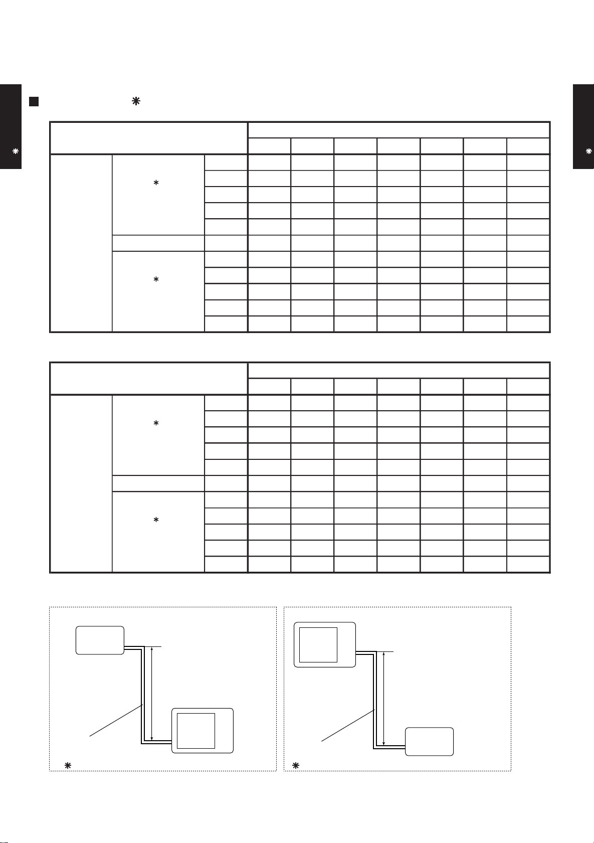
5. COEFFICIENT OF COMPENSATION FOR PIPE LENGTH
AND HEIGHT DIFFERENCE
This table is created using the maximum capacity.
MODEL : AO A36L
COOLING
OUTDOOR UNIT
AO A36-45L
1
Indoor unit is upper
than outdoor unit.
Height
difference H
(m)
2
Indoor unit is under
than outdoor unit
HEATING
1
Indoor unit is upper
than outdoor unit.
Height
difference H
(m)
2
Indoor unit is under
than outdoor unit
30 - - - -
20 - - -
10 - -
7.5 -
5
0 1.009 1.000 0.985 0.940 0.929 0.926 0.905
-5
-7.5 -
-10 - -
-20 - - -
-30 - - - -
30 - - - -
20 - - -
10 - -
7.5 -
5
0 0.978 1.000 1.016 0.985 0.971 0.950 0.927
-5
-7.5 -
-10 - -
-20 - - -
-30 - - - -
5 7.5 10 20 30 40 50
0.988 0.973 0.929 0.918 0.914 0.894
1.001 0.992 0.977 0.932 0.921 0.918 0.898
1.009 1.000 0.985 0.940 0.929 0.926 0.905
1.000 0.985 0.940 0.929 0.926 0.905
5 7.5 10 20 30 40 50
1.000 1.016 0.985 0.971 0.950 0.927
0.978 1.000 1.016 0.985 0.971 0.950 0.927
0.973 0.995 1.011 0.980 0.966 0.945 0.923
0.993 1.009 0.978 0.963 0.943 0.920
Pipe length (m)
0.884 0.881 0.862
0.910 0.899 0.896 0.876
0.969 0.925 0.914 0.911 0.890
0.985 0.940 0.929 0.926 0.905
0.940 0.929 0.926 0.905
0.929 0.926 0.905
Pipe length (m)
0.971 0.950 0.927
0.985 0.971 0.950 0.927
1.016 0.985 0.971 0.950 0.927
1.006 0.975 0.961 0.940 0.918
0.966 0.951 0.931 0.909
0.942 0.921 0.899
OUTDOOR UNIT
AO A36-45L
Indoor unit
H
Outdoor unit
Connection pipe
1
Indoor unit is upper than outdoor unit.
Height difference H
Outdoor unit
Connection pipe
2
Indoor unit is under than outdoor unit.
- (02 - 05) -
H
Indoor unit
Page 34
This table is created using the maximum capacity.
MODEL : AO A45L
COOLING
OUTDOOR UNIT
AO A36-45L
1
Indoor unit is upper
than outdoor unit.
Height
difference H
(m)
2
Indoor unit is under
than outdoor unit
HEATING
1
Indoor unit is upper
than outdoor unit.
Height
difference H
(m)
2
Indoor unit is under
than outdoor unit
30 - - - -
20 - - -
10 - -
7.5 -
5
0 1.009 1.000 0.995 0.949 0.938 0.935 0.914
-5
-7.5 -
-10 - -
-20 - - -
-30 - - - -
30 - - - -
20 - - -
10 - -
7.5 -
5
0 0.978 1.000 1.016 0.985 0.971 0.950 0.927
-5
-7.5 -
-10 - -
-20 - - -
-30 - - - -
5 7.5 10 20 30 40 50
0.988 0.983 0.938 0.927 0.924 0.903
1.001 0.992 0.987 0.942 0.931 0.927 0.907
1.009 1.000 0.995 0.949 0.938 0.935 0.914
1.000 0.995 0.949 0.938 0.935 0.914
5 7.5 10 20 30 40 50
1.000 1.016 0.985 0.971 0.950 0.927
0.978 1.000 1.016 0.985 0.971 0.950 0.927
0.973 0.995 1.011 0.980 0.966 0.945 0.923
0.993 1.009 0.978 0.963 0.943 0.920
Pipe length (m)
0.893 0.890 0.870
0.919 0.908 0.905 0.885
0.979 0.934 0.923 0.920 0.899
0.995 0.949 0.938 0.935 0.914
0.949 0.938 0.935 0.914
0.938 0.935 0.914
Pipe length (m)
0.971 0.950 0.927
0.985 0.971 0.950 0.927
1.016 0.985 0.971 0.950 0.927
1.006 0.975 0.961 0.940 0.918
0.966 0.951 0.931 0.909
0.942 0.921 0.899
OUTDOOR UNIT
AO A36-45L
Indoor unit
H
Outdoor unit
Connection pipe
1
Indoor unit is upper than outdoor unit.
Height difference H
Outdoor unit
Connection pipe
2
Indoor unit is under than outdoor unit.
- (02 - 06) -
H
Indoor unit
Page 35

6. ADDITIONAL CHARGE CALCULATION
Refrigerant type
R410A
3350
50g/m
MODEL : AO A36L, AO A45L
Refrigerant amount g
OUTDOOR UNIT
AO A36-45L
REFRIGERANT CHARGE
Pipe length m 20 30 40 50
Additional charge g 0 (Chargeless) +500 +1000 +1500
OUTDOOR UNIT
AO A36-45L
- (02 - 07) -
Page 36

7. AIR FLOW
Air flow
Lower fan
3884
Upper fan
850
m3/h
6600
l/s
1833
Number of
rotations
(r.p.m)
750
CFM
Number of
rotations
(r.p.m)
Upper fan
850
m3/h
6600
l/s
1833
Lower fan
750
CFM
3884
Air flow
MODEL : AO A36L, AO A45L
COOLING
OUTDOOR UNIT
AO A36-45L
HEATING
OUTDOOR UNIT
AO A36-45L
- (02 - 08) -
Page 37

8. OPERATION NOISE
8-1. NOISE LEVEL CURVE
COOLING
MODEL : AO A36L
80
70
OUTDOOR UNIT
AO A36-45L
60
50
40
30
20
Octave band sound pressure level, dB:(0dB=0.0002µbar)
10
0
63 125 250 500 1,000 2,000 4,000 8,000
Octave band center frequency,Hz
NC-65
NC-60
NC-55
NC-50
NC-45
NC-40
NC-35
NC-30
NC-25
NC-20
NC-15
MODEL : AO A45L
80
70
60
50
40
30
20
Octave band sound pressure level, dB:(0dB=0.0002µbar)
10
0
63 125 250 500 1,000 2,000 4,000 8,000
Octave band center frequency,Hz
NC-65
NC-60
NC-55
NC-50
NC-45
NC-40
NC-35
NC-30
NC-25
NC-20
NC-15
OUTDOOR UNIT
AO A36-45L
HEATING
MODEL : AO A36L
80
70
60
50
40
30
20
Octave band sound pressure level, dB:(0dB=0.0002µbar)
10
NC-65
NC-60
NC-55
NC-50
NC-45
NC-40
NC-35
NC-30
NC-25
NC-20
NC-15
MODEL : AO A45L
80
70
60
50
40
30
20
Octave band sound pressure level, dB:(0dB=0.0002µbar)
10
NC-65
NC-60
NC-55
NC-50
NC-45
NC-40
NC-35
NC-30
NC-25
NC-20
NC-15
0
63 125 250 500 1,000 2,000 4,000 8,000
Octave band center frequency,Hz
- (02 - 09) -
0
63 125 250 500 1,000 2,000 4,000 8,000
Octave band center frequency,Hz
Page 38

8-2. SOUND LEVEL CHECK POINT
OUTDOOR UNIT
AO A36-45L
OUTDOOR UNIT
AO A36-45L
- (02 - 10) -
Page 39

9. ELECTRIC CHARACTERISTICS
Model Name AO A36L AO A45L
Voltage V
230
Power Supply
Frequency Hz
50
Max. Operating Current A 19.0 20.0
OUTDOOR UNIT
AO A36-45L
Starting Current A
Main Fuse (Circuit breaker)
Current
*1) Wiring Spec.
Power Cable
mm
A
2
*2)Limited wiring length m
15.0
30
5.3 - 6.0
17
OUTDOOR UNIT
AO A36-45L
*1) Wiring Spec. :
Selected Sample
(Selected based on Japan Electrotechnical Standard and Codes Committee E0005)
*2) Limited Wiring length :
This is the wiring length in case voltage descent is less than 2%.
When the wiring length becomes long, please select the wiring of a more larger diameter.
- (02 - 11) -
Page 40

10. SAFETY DEVICES
AO A36L AO A45L
Current fuse
(MAIN PRINTED CIRCUIT BOARD)
Current fuse
(MAIN PRINTED CIRCUIT BOARD)
Thermal protection program (COMPRESSOR TEMP.)
Thermal protection program (DISCHARGE TEMP.)
Protection form
25A 250V
10A 250V
Model
5A 250V
3.15A 250V
Compressor protection
Circuit protection
OFF : 110°C
ON : 80°C
OFF : 115°C
ON : After 7 minutes
OFF : 130±20°C
ON : 100±20°C
OFF : 4.2±0.1MPa
ON : 3.2±0.15MPa
OUTDOOR UNIT
AO A36-45L
Fan motor protection Thermal protection program
High Pressure Protection High Pressure Switch
Current fuse (NEAR THE TERMINAL)
Current fuse (NEAR THE TERMINAL)
OUTDOOR UNIT
AO A36-45L
- (02 - 12) -
Page 41

REMOTE CONTROLLER
4. WIRELESS REMOTE CONTROLLER
UTB - NA
:
D2D_RC002E/01
2006.09.22
Page 42
REMOTE CONTROLLER UTB- NA
1 2
FEATURES
Four kinds of timer setup (ON / OFF / PROGRAM / SLEEP) are possible.
Four kinds of timers. Easy operation.
Easy to change transmission code (4 patterns) by button operation.
Simple function setting
Setting of the air conditioner selection function is performed by remote controller.
Built-in timers
Select from four different timer programs (On/Off/Program/Sleep).
Program timer
The program timer operates the ON and OFF timer once within a 24 hour period.
REMOTE CONTROLLER UTB- NA
Sleep timer
The sleep timer function automatically corrects the temperature thermostat setting according to the
time setting to prevent excessive cooling and heating while sleeping.
Cooling operation/dry operation
When the sleep timer is set, the set temperature
automatically rises 1 °C every hour. The set
temperature can rise up to a maximum of 2 °C.
Timer setting
60min.
1 °C
2 °C
Heating operation
When the sleep timer is set, the set temperature
automatically drops 1 °C every 30 minutes. The
set temperature can drop to a maximum of 4 °C.
1 °C
2 °C
3 °C
4 °C
30min.
60min.
90min.
Timer setting
Simultaneously operation
After code change
Mixed-up
• Code selector switch eliminates unit
being wrongly switched.
(Up to 4 codes can be set.)
A B C D
A B
C
D
•Wide and precise
transmitting range.
1. Press the MODE button for
more than five seconds
to start the code change.
2. Press the or button to
select the desired code.
A B C D
3. Press the MODE button
again to end the code change.
- (04 - 01) -
Page 43

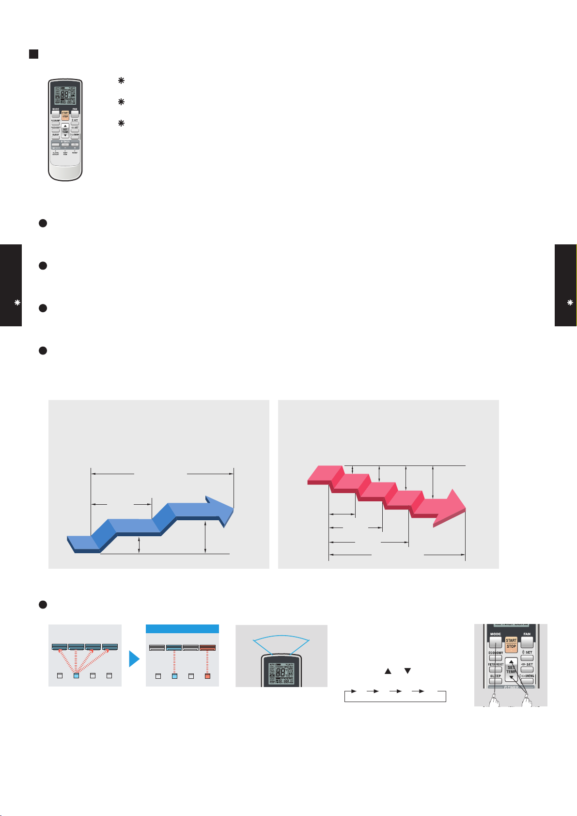
REMOTE CONTROLLER UTB- NA
FUNCTIONS
1
3
2
4
5
11
13
16
10
14
12
15
1
MODE button
Selects the operating mode (AUTO, HEAT, FAN, COOL, DRY).
/Start / end R.C. custom code change. (Max 4 types)
2
Economy button
3
Set temp. button ( / )
Set remote controller custom code buttons
Sets the indoor temp./ Sets R.C. custom code.
4
Filter reset button
5
Sleep button
Pressed to select sleep timer.
6
6
7
8
9
Fan button
Selects the fan speed (AUTO, QUIET, LOW, MED, HIGH).
7
START/STOP button
Pressed to start and stop operation.
8
Set button (Vertical)
Air flow direction vertical set button.
9
Set button (Horizontal)
Air flow direction horizontal set button.
10
Swing button
Air flow direction swing button.
11
Timer mode button
Pressed to select the timer mode. (OFF TIMER, ON TIMER,
PROGRAM TIMER, TIMER RESET)
REMOTE CONTROLLER UTB- NA
Display panel
17
18
19
20
21
22
23
24
25
12
Timer set ( / ) button
Sets the current time and on-off time.
13
Clock adjust button
Sets the current time.
14
Reset button
Used when replacing batteries.
15
Test run button
Used when testing the air conditioner after installation.
16
Signal transmitter
17
Temperature set display
18
Economy display
19
Operating mode display
20
Sleep display
21
Transmit indicator
22
Fan speed display
23
Swing display
24
Timer mode display
25
Clock display
SPECIFICATION
SIZE (H x W x D mm) 170 x 56 x 19
WEIGHT ( g ) 80
ACCESSORY Holder
- (04 - 02) -
 Loading...