

Page 1
COMPACT CASSETTE TYPE
AIR CONDITIONER
TECHNICAL MANUAL
Page 2

CONTENTS
1.FEATURE............................................................................................
2.OUTLINE AND DIMENSIONS.............................................................
2.1 INDOOR UNIT.................................................................................
2.2 OUTDOOR UNIT.............................................................................
3.DATA.....................................................................................................
3.1 PERFORMANCE CURVE...............................................................
3.2 TEMPERATURE RANGE................................................................
3.3 REFRIGERANT CHARGING..........................................................
3.4 AIR VELOCITY DISTRIBUTION.....................................................
3.4.1 MODEL : AU12/14...................................................................
3.4.2 MODEL : AU18........................................................................
3.5 SOUND LEVEL MEASUREMENT...................................................
1
3
3
4
5
5
6
6
7
7
8
9
3.5.1 SOUND LEVEL CHECK POINTS............................................
3.5.2 MODEL : AU12A/12R/14A/14R (INDOOR UNIT)....................
3.5.3 MODEL : AO12A/12R/14A/14R (OUTDOOR UNIT)................
3.5.4 MODEL : AU18A/18R (INDOOR UNIT)...................................
3.5.5 MODEL : AO18A/18R (OUTDOOR UNIT)...............................
3.6 OUTLET AIR....................................................................................
3.7 FRESH AIR......................................................................................
4.SPECIFICATIONS..................................................................................
9
10
11
12
13
14
14
15
Page 3
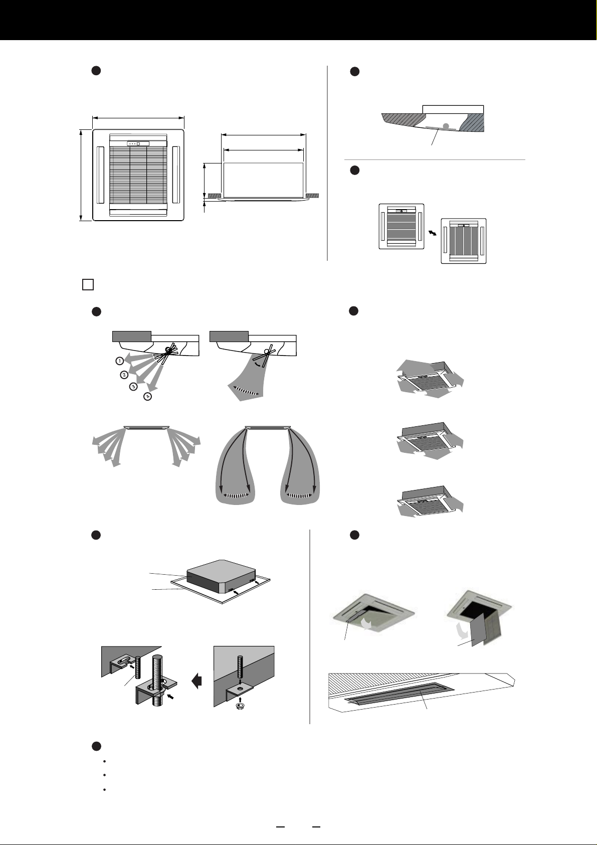
1.FEATURE
New Compact
Fit to Ceiling Tiles(600mm x 600mm)
650
650
Dimensions (12,000 to 14,000 and 18,000 BTU)
250
20
PRODUCT FEATURES
Auto Air Flow Direction & Auto Swing
600
580
Unit: mm
Flat & Simple Design
Illustration of a closed flap
FLAP
Removable Mount Grill
Adjusting to the ceiling
Vertical
pattern
Horizontal
pattern
4-way Air Flow System
You can select 2-way, 3-way,
4-way air flow to suit your needs.
4-WAY
SWING
-WAY
3
2-WAY
SWING
Light Weight & Easy Installation Easy Maintenance
Body : 18kg
Panel : 2.2kg
New hook design enable easier setting to
the anchor bolt
SWING
Filter wide opening
for easy maintenance
Filter
Easier cleaning
Removable and
Filter
Washable
Bolt
New Model
Present Model
Others
Auto Restart
Auto changeover operation(Heat & Cool Model)
Auto Closed Louver
1
Plastic flap with no velvet coating
Page 4
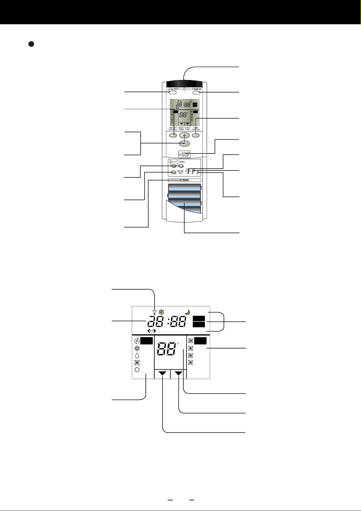
Wireless Remote Controller (Wall Fixing/Handy Type)
Signal Transmitter
SLEEP
Press to select SLEEP timer.
MASTER CONTROL Button
Press to select operating mode.
(AUTO, COOL, DRY, FAN, HEAT )
SET TEMP .
Press to set the unit’s thermostat.
SET TIME Buttons
Press to set the unit’s clock.
AIR FLOW DIRECTION Button
Use to set the desired air flow
direction & SWING function.
ENERGY SAVE Button
Set temperature is automatically
changed to reduce power consumption.
CODE CHANGE (Slide Switch)
Switching the remote control unit
code.( Max. 4 units )
CLOCK
AM
PM
AUTO
COOL
DRY
FAN
HEAT
TIMER
SLEEP
HM
TIMER RESET
ONOFF
ENERGY SAVE
C
A B C D
A B C D
ON
OFF
AUTO
HIGH
MED
LOW
TIMER Button
Press to select the timer mode.
(OFF TIMER, ON TIMER,
PROGRAM TIMER, RESET)
FAN CONTROL Button
Press to select fan speed.
(AUTO, HIGH, MED, LOW)
START / STOP Button
Press to start and stop operation.
TIME ADJUST Button
Set the current time.
TEST RUN
This button is used when testing
the air conditioner after installation.
ACL Button
This button is used when replacing
batteries.
BATTERY:
R03/ LR03 x 4
Transmit Indicator
Clock Display
Operating Mode Display
Remote Control Unit Display
CLOCK
AUTO
COOL
DRY
FAN
HEAT
TIMER
H
TIMER RESET
ONOFF
SLEEP
M
ENERGY SAVE
C
ON
OFF
AUTO
HIGH
MED
LOW
Timer Mode Display
Fan Speed Display
Temperature Set Display
Timer Set Indicator
Temperature Set Indicator
2
Page 5
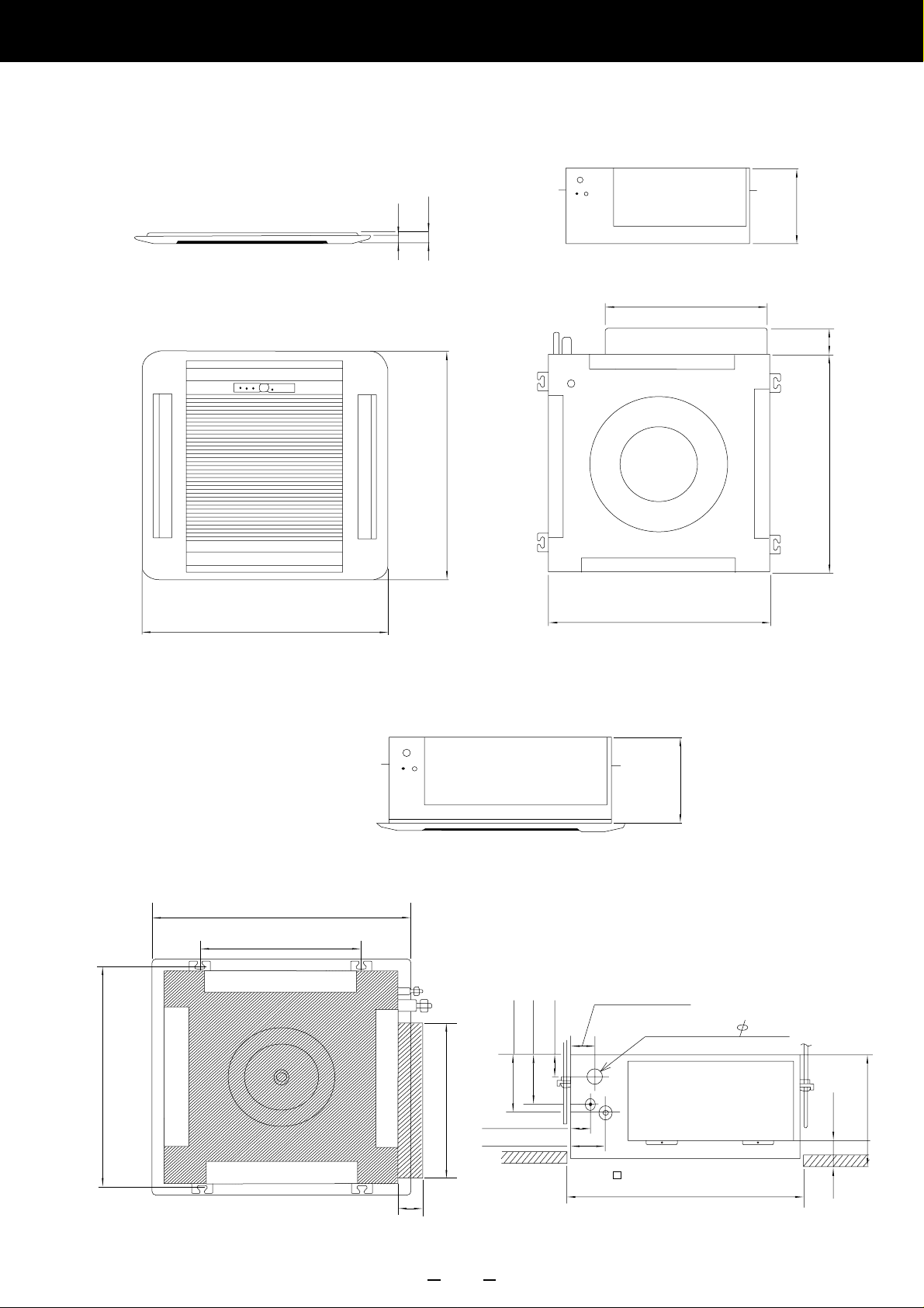
2.OUTLINE AND DIMENSIONS
2. OUTLINE AND DIMENSIONS
20mm
35mm
235mm
440mm
66mm
650mm
(Grille measurement)
650mm
(Hanging bolt position)
400mm
650mm
580mm
580mm
250mm
(Hanging bolt position)
606mm
66mm
440mm
3
46mm
86mm
111mm
131mm
60mm
47mm
(Ceiling opening measurement)
Drain pipe(I.D. 32mm)
600mm
54mm
250mm
Page 6
2.2 OUTDOOR UNIT
643mm
25mm
333mm
840mm
804mm
336mm
4
Page 7

3. DATA
3.1 PERFORMANCE CURVE
APPLICATION MODELS : AU12A,14A,18A
Cooling
140
130
AU12R,14R,18R
120
110
100
90
Capacity(%)Input(%)
80
29/21
29/19
27/19
25/19
23/19
23/17
70
130
120
110
100
90
29/21
29/19
27/19
25/19
23/19
23/17
80
70
60
10 15 20 25 30 35 40 45 50 55
Outdoor DB ( C)
Heating
Indoor
DB/WB ( C)
29/21
29/19
27/19
25/19
23/19
23/17
29/21
29/19
27/19
25/19
23/19
23/17
130
120
110
100
90
Capacity(%)
80
70
130
120
110
100
90
Input(%)
80
70
60
-5 0 5 10 15 20 25
Indoor
DB ( C)
15
20
25
25
20
15
Outdoor DB ( C) RH=85%
5
Page 8

3.2 TEMPRATURE RANGE
MODEL
TEMPERATURE RANGE
Indoor Unit Outdoor Unit
COOL
AU12A/14A/18A
DRY
COOL
AU12R/14R/18R
DRY
HEAT
3.3 REFRIGERANT CHARGING
Approx. 18 C to 32 C Approx. 10 C to 52 C
Approx. 18 C to 32 C Approx. 10 C to 52 C
Approx. 18 C to 32 C Approx. 10 C to 52 C
Approx. 18 C to 32 C Approx. 10 C to 52 C
Approx. 16 C to 30 C Approx. 5 C to 21 C
PIPE LENGTH
FULL
CHARGE
AMOUNT
12A
12R
14A
14R
18A
18R
16ft (5m) 33ft (10m) 49ft (15m) 66ft (20m)
950 g
( 33.5oz)
1,000 g
( 35.3oz)
1,000 g
( 35.3oz)
1,000 g
( 35.3oz)
1,170 g
( 41.3oz)
1,800 g
( 63.5oz)
1,000 g
( 35.3oz)
1,075 g
( 37.9oz)
1,050 g
( 37.0oz)
1,075 g
( 37.9oz)
1,245 g
( 43.9oz)
1,950 g
( 68.8oz)
1,050 g
( 37.0oz)
1,150 g
( 40.6oz)
1,100 g
( 38.8oz)
1,150 g
( 40.6oz)
1,320 g
( 46.6oz)
2,100 g
( 74.1oz)
1,100 g
( 38.8oz)
1,225 g
( 43.2oz)
1,150 g
( 40.6oz)
1,225 g
( 43.2oz)
1,395 g
( 49.2oz)
2,250 g
( 79.4oz)
Additional
refrigerant
g/m
10 g
( 0.35oz)
15 g
( 0.53oz)
10 g
( 0.35oz)
15 g
( 0.53oz)
15 g
( 0.53oz)
30 g
( 1.06oz)
6
Page 9

3.4 AIR VELOCITY DISTRIBUTION
3.4.1 AIR VELOCITY DISTRIBUTION
MODELS : AU12,AU14
22
11
0.5 0.5
0.25 0.25
7
Page 10

3.4.2 AIR VELOCITY DISTRIBUTION
MODELS : AU18
AIR DISCHARGE ANGLE
3
Downward
Upward
2
8
Page 11

3.5 SOUND LEVEL MEASUREMENT
3.5.1 SOUND LEVEL CHECK POINTS
INDOOR UNIT
1.5m
OUTDOOR UNIT
1m
AIR
hh2
9
Page 12
3.5.1 SOUND LEVEL CHECK POINTS
MODELS : AU12A/12R/14A/14R (INDOOR UNIT)
Old octave-band limiting frequencies, (Hz)
Below
75 150 300 600 1,200 2,400 4,800
75 150 300 600 1,200 2,400 4,800 9,600
80
1957 Noise Criteria
NC Curves
70
NC-65
NC-60
60
2
NC-55
-5
NC-50
50
NC-45
NC-40
40
Octave-band sound-pressure level dB 2 10 N/m
(0dB=0.0002µbar)
30
20
10
0
NC-35
NC-30
NC-25
NC-20
NC-15
63 125 250 500 1,000 2,000 4,000 8,000
New octave-band center frequencies (Hz)
10
Page 13
3.5.3 SOUND LEVEL CURVE
MODELS : AO12A/12R/14A/14R (OUTDOOR UNIT)
Old octave-band limiting frequencies (Hz)
Below
75 150 300 600 1,200 2,400 4,800
75 150 300 600 1,200 2,400 4,800 9,600
80
1957 Noise Criteria
NC Curves
70
NC-65
NC-60
60
2
NC-55
-5
NC-50
50
NC-45
40
Octave-band sound-pressure level dB 2 10 N/m
(0dB=0.0002µbar)
30
20
10
NC-40
NC-35
NC-30
NC-25
NC-20
NC-15
0
63 125 250 500 1,000 2,000 4,000 8,000
New octave-band center frequencies (Hz)
11
Page 14

3.5.4 SOUND LEVEL CURVE
MODELS : AU18A/18R (INDOOR UNIT)
Old octave-band limiting frequencies (Hz)
Below
75 150 300 600 1,200 2,400 4,800
75 150 300 600 1,200 2,400 4,800 9,600
80
1957 Noise Criteria
NC Curves
70
NC-65
NC-60
60
2
NC-55
-5
NC-50
50
NC-45
40
30
Octave-band sound-pressure level dB 2 10 N/m
(0dB=0.0002µbar)
20
10
NC-40
NC-35
NC-30
NC-25
NC-20
NC-15
0
63 125 250 500 1,000 2,000 4,000 8,000
New octave-band center frequencies (Hz)
12
Page 15

3.5.5 SOUND LEVEL CURVE
MODELS : AO18A/18R (OUTDOOR UNIT)
Old octave-band limiting ferquencies (Hz)
Below
75 150 300 600 1,200 2,400 4,800
75 150 300 600 1,200 2,400 4,800 9,600
80
1957 Noise Criteria
NC Curves
70
NC-65
NC-60
60
2
NC-55
-5
NC-50
50
NC-45
40
Octave-band sound-pressure level dB 2 10 N/m
(0dB=0.0002µbar)
30
20
10
NC-40
NC-35
NC-30
NC-25
NC-20
NC-15
0
63 125 250 500 1,000 2,000 4,000 8,000
New octave-band center frequencies (Hz)
13
Page 16

3.6 OUTLET AIR
Duct (inside Dia. 150mm)
L
Duct (inside Dia. 150mm)
L
(mmAq)
(mmAq)
8
240V Hi
7
6
5
220V Hi
240V Lo
220V Lo
L=5m
4
3
2
1
0
0 2 4 6 8
8
240V Hi
7
220V Hi
6
240V Lo
5
220V Lo
4
L=5m
3
(m / min)
3
2
1
0
0 2 4 6 8
3
(m / min)
3.7 FRESH AIR
Duct (inside Dia. 150mm)
7
6
5
(mmAq)
4
3
P
Duct Fan
Static pressure
required to take
in fresh air
2
1
0
0 0.1 0.2 0.3
3
(m / min)
14
Page 17

4. SPECIFICATIONS
INDOOR UNIT
Model
Capacity Cooling
Heating
Electrical
E.E.R.
Moisture Removal ( /hr)
Refrigerant (R22) ( g )
Fan Speed
(r.p.m.)
Air
Circulation
3
(m /h)
Noise
(dBA)
Dimensions
(H x W x D)
Weight
Connection
Pipe
Compressor
Operation Range
Remote Controller
Auto Restart Function
Cooling/heating capacities are based on the following conditions.
Models
Y
T
Length (Max)
Height (Max)
Diameter Small/Large
Indoor temp.
Outdoor temp. : 35 C DB/24 C WB
OUTDOOR UNIT
GRILLE
Power supply ( V )
Frequency ( Hz )
Current Cooling ( A )
Heating ( A )
Input Cooling ( kW )
Heating ( kW )
Starting Current ( A )
Cooling ( kW/kW )
Heating ( kW/kW )
Hi
Indoor
Outdoor Hi / Lo
Indoor
Outdoor
Indoor
Outdoor
Net
Gross
Net
Gross
I : IN
O : OUT
Cooling Heating
: 27 C DB/19 C WB
Med
Low
Hi
Med
Low
Hi
Med
Low
Indoor
Outdoor
Grille
Indoor
Outdoor
Grille
Indoor
Outdoor
Grille
Cooling
Heating
AU 12A
AO 12AZAL
UTG-UDYA-W UTG-UDYA-W UTG-UDYA-W UTG-UDYA-W UTG-UDYA-W UTG-UDYA-W
( kW )
3.65 - 3.70
( kW )
220 - 240
50
6.3 - 6.3
1.32 - 1.36
40
2.77 - 2.72
1.6
950
740
660
580
580 / 280
550
500
440
2,500
40.0
38.0
35.0
49.0
( mm )
( mm )
( mm )
( mm )
( mm )
( mm )
( kg )
( kg )
( kg )
( m )
( m )
(mm)
18 / 23
63 / 72
Recipro
I:18 32, O:10 52
( C)
( C)
Wireless
Yes
Indoor temp.
Outdoor temp. : 7 C DB/ 6 C WB
Indoor temp.
Outdoor temp. : 7 C DB/ 6 C WB
AU 12R
AO 12RZAL
3.55 - 3.60
4.00 - 4.10
220 - 240
50
6.3 - 6.3
6.1 - 6.1
1.32 - 1.36
1.28 - 1.32
40
2.69 - 2.65
3.13 - 3.11
1.6
1,000
740
660
580
580 / 280
550
500
440
2,500
40.0
38.0
35.0
49.0
18 / 23
64 / 72
Recipro
I:18 32, O:10 52
I:16 30, O: -5 21
Wireless
Yes
: 20 C DB
: 21 C DB
AU 14A
AO 14AZAL
4.00 - 4.10
220 - 240
50
7.4 - 7.4
1.55 - 1.60
45
2.58 - 2.56
1.8
1,000
740
660
580
580 / 280
550
500
440
2,500
41.0
38.0
35.0
49.0
235 x 580 x 580 + 70
643 x 840 x 336
35 x 650 x 650
280 x 710 x 750
750 x 959 x 429
70 x 720 x 720
18 / 23
63 / 72
Recipro
I:18 32, O:10 52
Wireless
Yes
AU 14R
AO 14RZAL
3.90 - 4.00
4.35 - 4.50
220 - 240
50
7.4 - 7.4
7.3 - 7.3
1.55 - 1.60
1.50 - 1.55
45
2.52 - 2.50
2.90 - 2.90
1.8
1,000
740
660
580
580 / 280
550
500
440
2,500
41.0
38.0
35.0
49.0
18 / 23
64 / 72
2.2 / 4.3
20
8
6.35 / 12.7
Recipro
I:18 32, O:10 52
I:16 30, O: -5 21
Wireless
Yes
50Hz
AU 18A
AO 18AZCL
4.95 - 5.10
220 - 240
50
9.2 - 9.1
2.00 - 2.10
50
2.48 - 2.43
2.1
1,170
820
740
620
740 / 280
650
550
490
2,800
43.0
40.0
36.0
54.0
18 / 23
66 / 73
Recipro
I:18 32, O:10 52
Wireless
Yes
AU 18R
AO 18AZCL
4.85 - 5.00
5.30 - 5.45
220 - 240
50
8.8 - 8.6
8.8 - 8.6
1.90 - 2.00
1.90 - 2.00
50
2.55 - 2.50
2.79 - 2.73
2.1
1,800
820
740
620
740 / 280
650
550
490
2,800
43.0
40.0
36.0
54.0
18 / 23
68 / 76
Recipro
I:18 32, O:10 52
I:16 30, O: -5 21
Wireless
Yes
Note : In the above square, put the T or Y by a destination
15
Page 18

1116, Suenaga, Takatsu-ku, Kawasaki 213-8502, Japan
9903K1469
April 1999 Printed in Japan
 Loading...