

Page 1

SPLIT TYPE
AIR CONDITIONER
CASSETTE
Models Indoor unit Outdoor unit
AUG12RBAB AOG12RMAJL
AUY12RBAB AOY12RMAJL
type (50Hz)
2004.05.18
CONTENTS
SPECIFICATIONS . . . . . . . . . . . . . . . . . . . . . . . . . . . . . . . . . . . . . . . . 1
OUTLINE AND DIMENSIONS . . . . . . . . . . . . . . . . . . . . . . . . . . . . . . 2
CIRCUIT DIAGRAM . . . . . . . . . . . . . . . . . . . . . . . . . . . . . . . . . . . . . . 4
ERROR CONTENTS . . . . . . . . . . . . . . . . . . . . . . . . . . . . . . . . . . . . . 5
REFRIGERANT SYSTEM DIAGRAM . . . . . . . . . . . . . . . . . . . . . . . . 6
INDOOR PRINTED CIRCUIT BOARD CIRCUIT DIAGRAM . . . . . 7
DISASSEMBLY ILLUSTRATION . . . . . . . . . . . . . . . . . . . . . . . . . . . . 8
PARTS LIST . . . . . . . . . . . . . . . . . . . . . . . . . . . . . . . . . . . . . . . . . . . 15
Page 2
SPECIFICATIONS
TYPE COOL & HEAT
INDOOR UNIT AUG12RBAB AUY12RBAB
OUTDOOR UNIT AOG12RMAJL AOY12RMAJL
COOLING CAPACITY (kW) 3.55 - 3.60
HEATING CAPACITY (kW) 4.00 - 4.10
ELECTRICAL DATA
POWER SOURCE (V) 220 - 240V
FREQUENCY (Hz) 50
RUNNING CURRENT (A)
INPUT WATTS (kW)
E.E.R. (kW/kW)
STARTING CURRENT (A) 35
MOISTURE REMOVAL ( /hr) 1.6
AIR CIRCULATION-Hi (m3/hr) 550
REFRIGERANT R-22 (g) 1,100
COOLING 5.9 - 6.1
HEATING 5.7 - 5.8
COOLING 1.26 - 1.34
HEATING 1.20 - 1.28
COOLING 2.82 - 2.69
HEATING 3.33 - 3.20
COMPRESSOR
TYPE Hermetic type
CODE
RH231VHAT
220 - 240V 50Hz
FAN MOTOR
POWER SOURCE (V) 240
TYPE MFA-14GTCT
INDOOR UNIT
OUTDOOR UNIT
HI-SPEED (r.p.m.) 730
MED-SPEED (r.p.m.) 670
LO-SPEED (r.p.m.) 590
TYPE MFB-14NTT
HI / LO (r.p.m.) 740 / 440
DIMENSIONS
INDOOR UNIT 235 x 580 x 580 +70
OUTDOOR UNIT H x W x D (mm) 530 x 750 x 250
GRILLE 35 x 650 x 650
WEIGHT
INDOOR UNIT 18 / 23
OUTDOOR UNIT GROSS / NET (kg) 37 / 39
GRILLE 2.2 / 4.3
2004.05.18
REFRIGERANT CHARGE (R-22)
PIPE LENGTH
MODELS
FULL CHARGE
AMOUNT
AUG12RBAB
AUY12RBAB
7.5 m 10 m 15 m 20 m
1,100 g 1,138 g 1,213 g 1,288 g 15 g / m
- 1 -
Additional
refrigerant
Page 3
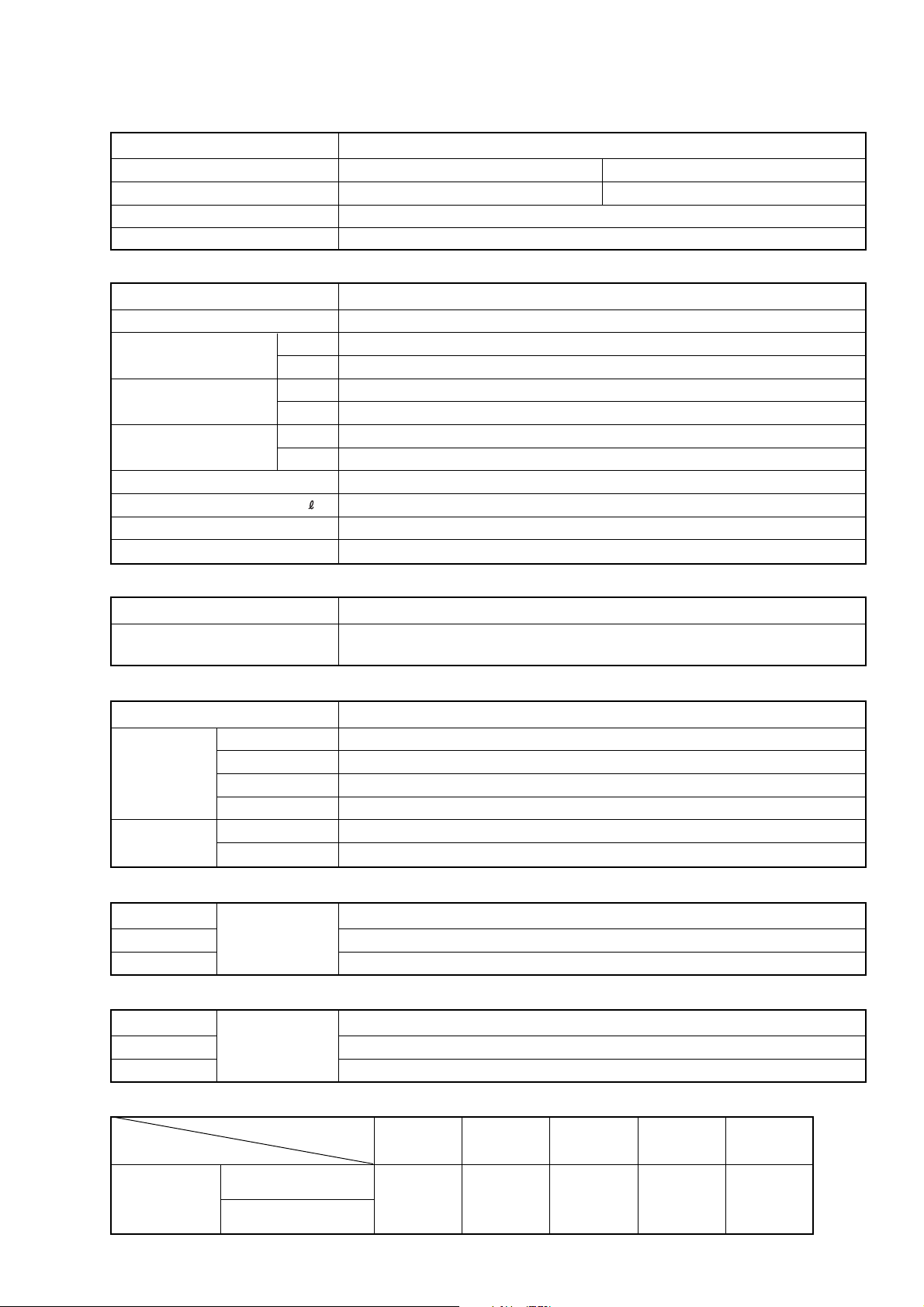
OUTLINE AND DIMENSIONS
20
235
66
250
440
580650
( 650) (Grille measurement)
650
(Hanging bolt position)
400
(Hanging bolt position)
606
650
580 66
440
35
600
(Ceiling opening measurement)
250
60
86
Drain pipe (I.D. 32)
54
46
131
111
47
INDOOR UNIT
(unit : mm)
- 2 -
2004.05.18
Page 4
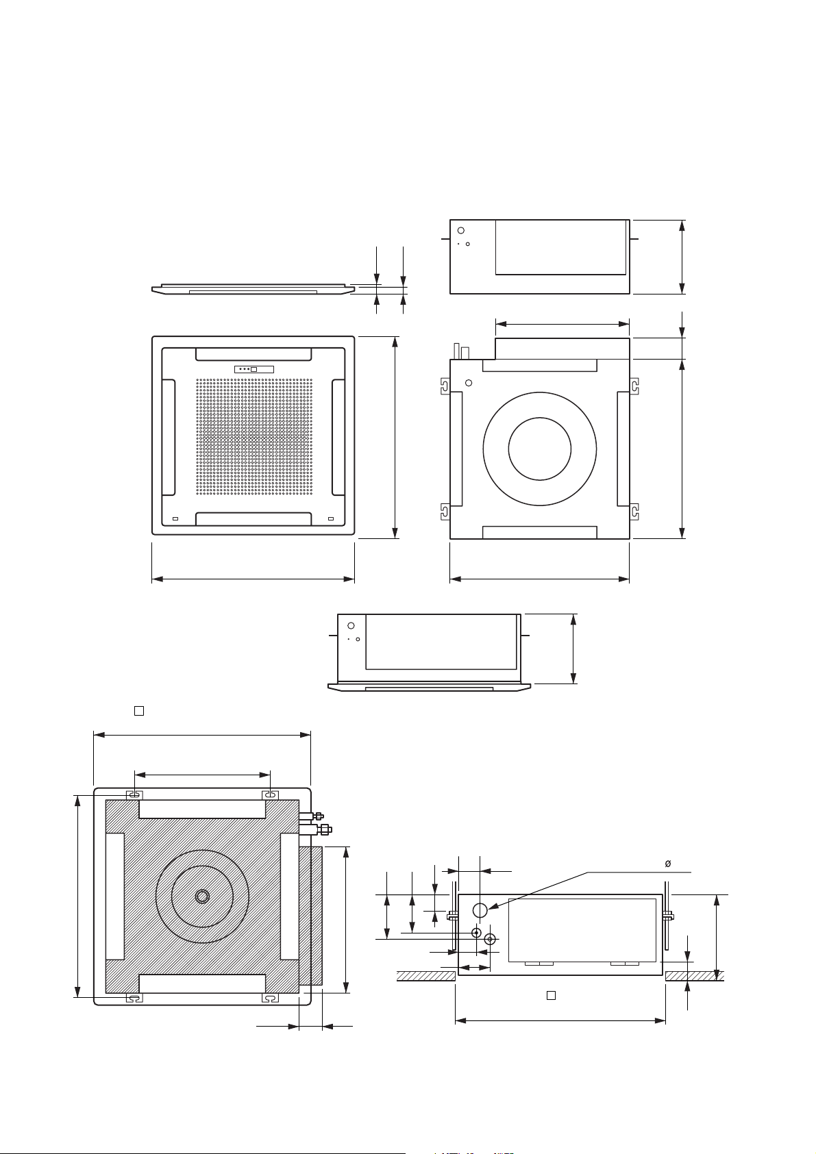
OUTDOOR UNIT
13
(unit : mm)
250
750
530
540
285
2004.05.18
- 3 -
Page 5
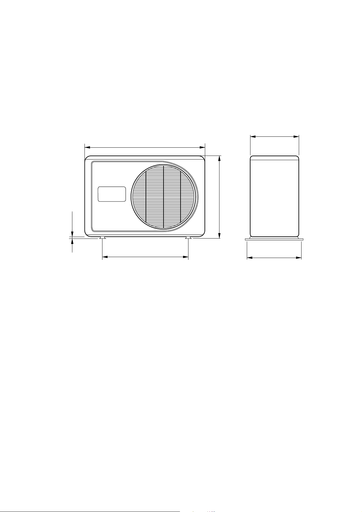
Models : AUG12RBAB
THERMISTOR (PIPE TEMP.)
THERMISTOR (ROOM TEMP.)
RED
CONTROL BOARD
STEP
MOTOR
FAN MOTOR
CAPACITOR
WHITE
BROWN
RED
ORANGE
YELLOW
WHITE
BLACK
YELLOW
GRAY
GRAY
GREEN/YELLOW
BLUE
DISPLAY BOARD
PURPLE
GREEN
CN13
CN10
1
2
21
3
4 5
1
2
CN2
123
3
CN6
21
CN19
CN15
1
BLACK
BLACK
BLACK
BLACK
87654321
CN201
M
CN1
BLACK
BLACK
N
L
BLACK
GRAY
RED
BROWN
BLUE
BLACK
WHITE
WHITE
YELLOW
YELLOW
M
FAN
MOTOR
DRAIN PUMP
MOTOR
FLOAT
SWITCH
FILTER BOARD
TERMINAL
CN5
123456
412536978
FM
4356
2
(N)
1
(L)
Use T3.15A–250V
Fuse on F101
3
CN712CN8
12
1
13
BROWN
RED
ORANGE
YELLOW
WHITE
BLUE
GRAY
PURPLE
PINK
TO OUTDOOR UNIT
12345
87654321
87654321
AUY12RBAB
CIRCUIT DIAGRAM
Models : AOG12RMAJL
AOY12RMAJL
OVERLOAD
PROTECTOR
BLACK
C
COMPRESSOR
1
4
MAIN RELAY
TO POWER SUPPLY
R
S
6
5
BLACK
COMPRESSOR
CAPACITOR
RED
WHITE
LN1(L) 2(N) 3
WHITE
WHITE
BROWN
BROWN
BLACK
BLACK
- 4 -
4 56
WHITE
BLUE
ORANGE
FUSE 5A
BLACK
FAN MOTOR
CAPACITOR
BLACK
TERMINAL
RED
FAN MOTOR
THERMAL
PROTECTOR
4-WAY
VALVE COIL
SV
BLACK
TO INDOOR UNIT
2004.05.18
Page 6
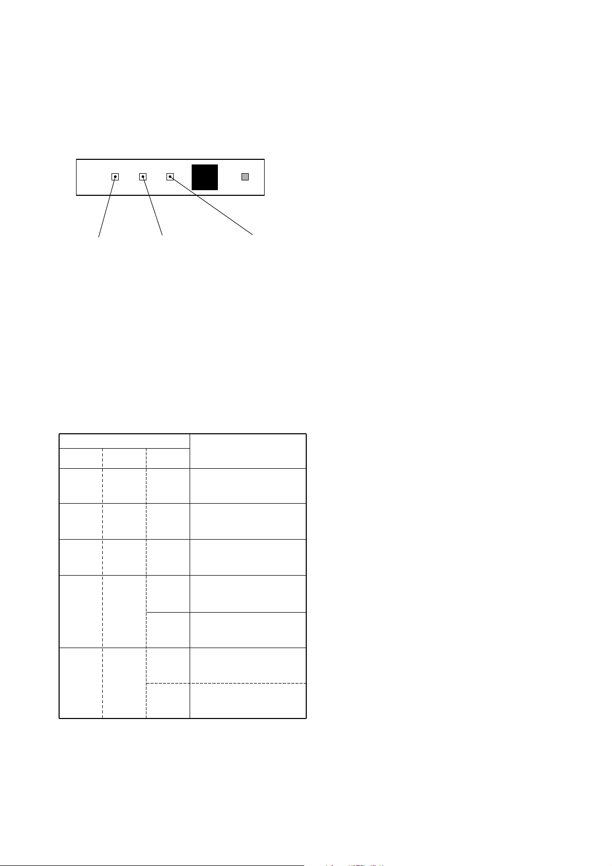
ERROR CONTENTS
SWING TIMER OPERATION
MANUAL
AUTO
SWING LAMP
(Orange)
TIMER LAMP
(Green)
OPERATION LAMP
(Red)
Operation can be checked by lighting and flashing of the grille
display section OPERATION and TIMER lamps.
Perform judgment in accordance with the following.
TEST RUNNING
When the air conditioner is run by pressing the remote control
unit test run button, the OPERATION and TIMER lamps flash
slowly at the same time.
ERROR
The OPERATION, TIMER, and SWING lamps operate as
follows (Table 1) according to the error contents.
CHECK ITEMS
1. INDOOR UNIT
(1) Is operation of each button on the remote control unit
normal?
(2) Does each lamp light normally?
(3) Do not air flow direction louvers operate normally?
(4) Is the drain normal?
(5) Is there any abnormal noise and vibration during operation?
2. OUTDOOR UNIT
(1) Is there any abnormal noise and vibration during operation?
(2) Will noise, wind or drain water from the unit disturb the
neighbors?
(3) Is there any gas leakage?
• Do not operate the air conditioner in the test running state
for a long time.
Table 1
Error display
OPERATION TIMER SWING
lamp lamp lamp
Blinks Blinks Goes off
Pulses
4 times
Pulses
6 times
Pulses
2 times
Pulses
3 times
Blinks Goes off
Blinks Goes off
Goes off
Blinks
Blinks
Goes off
Blinks
Blinks
Error contents
Model information abnormal
(permanent type)
Drain abnormal (permanent type)
Indoor fan abnormal
Room air temperature thermistor
open circuit
Room air temperature thermistor
short circuit
Piping thermistor open circuit
Piping thermistor short circuit
2004.05.18
- 5 -
Page 7

REFRIGERANT SYSTEM DIAGRAM
OUTDOOR UNIT
Refrigerant pipe
12.7 mm (1/2")
Refrigerant pipe
6.35 mm (1/4")
Charging valve
INDOOR UNIT
Evaporator
Cooling
Heating
: Flare coupling
4-Way
valve
Compressor
Strainer
Condenser
Dryer
Capillary
tube
Muffler
Models : AUG12RBAB / AOG12RMAJL
AUY12RBAB / AOY12RMAJL
- 6 -
2004.05.18
Page 8

CR5
1000P
<R>
14V
I C4 (7/7)
uPA2003GR
I C5 (1/7)
uPA2003GR
R56
14V
R57 1.0K
<1/10W>
I C6 (2/7)
uPA2003GR
5V
BZ1
PKM13EPY-4000
NC
NC
NC
NC
NC
14V
R54 47
<1/10W>
R51 1.0K
<1/10W>
C40
0.01
<F>
C41
10/
25V
+
5V
C42
0.01
<F>
I C7
BR93LC46RF
C39
0.1
<F>
5V
5V
5V
5V
C38
0.01
<F>
R52
10K
<1/10W>
R53
10K
<1/10W>
R48
10K
<1/10W>
R49 1.0K
<1/10W>
R47 390
<1/10W>
C37
0.1
<F>
C34
0.1
<F>
Q4
DTC124EKA
CN14
B4B-XH-AM
CN13
B8B-XASK-1-A
HEAT EXCHANGER THERMISTOR
ROOM TEMPERATURE THERMISTOR
5V
MANUAL AUTO
SWITCH
SW201
EVQ-PAG-04K
CN201
7P-SCN
INDICATOR PCB
EZ-097HHSE-D
C201
0.1
<F>
C202
10/
25V
+
PHA201
SBX1810
-22
OUT
LOUVER
OPERATE
TIMER
D203 SLR-325 <ORG>
D202 SLR-325 <GRN>
D201 SLR-325 <RED>
R201 330 <1/4W>
R202 330 <1/4W>
R203 330 <1/4W>
1
2
3
4
8
5
7
6
M
LOUVER
( UP / DOWN )
CN10
B5B-XASK-1-A
CN10-1
CN10-5
CN10-4
CN10-3
CN10-2
CN13-1
CN13-4
CN13-3
CN13-2
CN13-8
CN13-6
CN13-7
CN13-5
UL1430
AWG28
UL1430
AWG28
BROWN
RED
ORANGE
YELLOW
GRAY
WHITE
PURPLE
BLUE
BROWN
RED
ORANGE
YELLOW
GRAY
WHITE
PURPLE
BLUE
BROWN
RED
ORANGE
YELLOW
WHITE
BROWN
RED
ORANGE
YELLOW
WHITE
GRAY
GRAY
BLACK
BLACK
CN8-1
CN8-2
CN7-2
CN7-1
CN14-1
CN14-3
CN14-4
CN14-2
HA
JEM-A
5V
CN8
B2B-XASK-1-A
CN7
B2B-XAKK-1-A
R43
10K (1%)
<1/10W>
R45
49.9K (1%)
<1/10W>
C32
1000P
<R>
C35
1000P
<R>
R44 1.0K
<1/10W>
R46 1.0K
<1/10W>
R50 10K <1/10W>
R77 - R79
10K <1/10W> x 3
D0
D1
CK
CS
VCC
NC
NC
GND
1
2
3
48
7
6
5
6
71110
8
9
1
16
116
4
2
15
13
7
5
3
1
10
12
14
16
5V
C31
0.01
<F>
C43
0.01
<F>
C16
0.01
<F>
B Z
R58 10K <1/10W>
R75 10K <1/10W>
R76 10K <1/10W>
R100 10K <1/10W>
R59 10K <1/10W>
R97 10K <1/10W>
R99 10K <1/10W>
R98 10K <1/10W>
5V
5V
CR1 10K <1/10W>
CR2 10K <1/10W>
CR4 10K <1/10W>
CR3 10K <1/10W>
JM11
5V
5V
C1
0.1
<F>
CR7
0.01
<F>
RJ2 10K
<1/10W>
RJ1 1.0K
<1/10W>
C49
0.1
<F>
C45
0.1
<F>
C44
0.1
<F>
I C8
PST600C
R55 10K
<1/10W>
R67 1.0K
<1/10W>
R68 10K
<1/10W>
X1
1.5MHz
2
13
70 69
X1
X2
CN15-1
CN15-3
CN15-2
UL1430 AWG22
BLACK
UL1430 AWG22 BLACK
CN15
B3B-XARK-1-A
FLOAT SWITCH
R71 1.0K <1/10W>
R72 1.0K <1/10W>
R81 1.0K <1/10W> R80 10K <1/10W>
R69 10K <1/10W>
R70 10K <1/10W>
76
77
35
34
8
9
10
6
28
29
30
31
32
62
27
18
17
16
13
12
11
5
50
53
24
23
22
25
15
14
26
54
55
66
65
42
80
79
78
61
64
73
60
46
45
44
43
59
58
57
56
21
20
19
52
51
49
48
47
41
40
39
38
37
36
63
72
71
33
67
4
7
75
68
74
3
2
1
P15
P16
P17
VDD0
VDD1
AVREF0
AVREF1
AGND
GND0
GND1
I C
XT2
P02
P60
P61
P62
P63
P64
P65
P33
P34
P35
P37
P120
P40
P41
P42
P124
P125
P126
P127
P67
P30
P31
P32
RESET
XT1
P03
P00
P12
P13
P14
P66
P04
P05
P123
P122
P47
P23
P24
P46
P43
P44
P45
P121
P36
P130
P20
P21
P22
P25
P26
P27
P50
P01
P55
P54
P53
P52
P51
P131
P72
P71
P70
P56
P57
P11
P10
CN9-5
CN9-1
CN9-2
CN9-3
CN9-4
5V
5V
TEST
CN9
B5P-SHF-1AA
C22 - C25
0.01 x 4
<F>
R25 - R28
1.0K <1/10W> x 4
R21 - R24
10K <1/10W> x 4
C26 - C29
0.01 x 4
<F>
R33 - R36
1.0K <1/10W> x 4
R29 - R32
10K <1/10W> x 4
5V
R15 - R17
10K <1/10W> x 3
5V
5V
5V
CR6
0.01
<F>
C47
0.1
<F>
C15
0.1
<F>
+
C14
100/
6.3V
C13
0.1
<F>
7805
I C3
R10
10K
<1/10W>
R9 390
<1/10W>
NC
JM10
C19 - C21
0.01 x 3
<F>
R18 1.0K <1/10W>
R19 1.0K <1/10W>
R20 1.0K <1/10W>
14V
JM1
JM3
JM2
R8 10K
<1/10W>
+
C9
1000
/25V
D6
D2FL20U
C54
0.01
<F>
T1
SWITCHING TRANSFORMER
ZFT29B01
SECONDARY
C8
100/
6.3V
+
PRIMARY
R7 330
<1/4W>
5V
R93 - R96
10K <1/10W> x 4
Q3
DTC124EKA
C17
0.01
<F>
C18
0.01
<F>
R12 1.0K
<1/10W>
R13 10K
<1/10W>
JM6
14V
14V
R11 56K
<1W>
D8
D1F60
I C9
TLP621
(D4) - GB
IO
G
SSR1
G3MC-202P-VD
+
-
VA2
470V
NC
NC
14V
5V
R37 10K <1/10W>
R39 10K <1/10W>
R38 10K <1/10W>
I C6 (5/7)
uPA2003GR
I C5 (6/7)
uPA2003GR
R40 1.0K <1/10W>
R41 1.0K <1/10W>
R42 1.0K <1/10W>
SW1
DSS803
K 4
K 3
K 1
K 2
K 8
K 7
K 5
K 6
9
8
1
2
3
4
5
12
13
14
15
16
8
9
7
6
5
4
3
2
10
11
12
13
14
15
C6
4700P
R5 62K
<2W>
R4 330K
<2W>
D5
1SR139-600
D10
1SR139-600
Q1
2SC4236
C7
0.047
R6 100
<1/2W>
D2
D1FL20U
D4
D1FL20U
D3
MTZJ5.1B
R2 1.5
<2W>
R3 100
<1/10W>
Q2
2SC1815
+
R1 3.3
<5W>
D1
D3SB60
C5
100/450V
TM101
TM102
FH102
FH101
F101
3.15A
<BET>
VA102
470V
C102
0.22
VA101
470V
SA101
<3600V>
E101 W103
W104
LF101
ELF17N015A
C104
0.01
C103
0.01
C106
0.01
C105
0.01
C101
0.22
L
N
CN1
B2P3-VH-B-C
CN5
B6P11-VH-B
UL1015 AWG16
GREEN
UL1015 AWG18 WHITE
UL1015 AWG18
BLACK
CN1-1
CN1-2
PURPLE
PINK
RED
BLUE
WHITE
CN5-1
CN5-2
CN5-6
CN5-5
CN5-4
CN5-3
YELLOW
YELLOW
K2
G5S-1
K3
G5S-1
K1
G5S-1
K8
G5NB-1A
K4
G5NB-1A
K5
G5NB-1A
K6
G5S-1
K7
G5NB-1A
CN2
B3P5-VH-B-R
CN6
B2P3-VH-B-E
CN19
B2P3-VH-B-R
FAN CAPACITOR
2.3uF
450V AC
CR8
TA120033
R88 120 <1/2W>
C3 0.22
C4 0.22
R89 120
<1/2W>
FAN MOTOR
TERMINAL BOARD
F M
M
DRAIN PUMP
POWER SOURCE
220 / 240V
50Hz
OUTDOOR UNIT
E
1
6
5
4
3
2
UL1015 AWG20 BLUE
UL1015 AWG20 BROWN
UL1015 AWG20 RED
H I
LO
4WV
CN6-2
CN6-1
CN19-1
CN2-3
CN2-2
CN2-1
UL1015 AWG22
BLACK
UL1015 AWG22
BLACK
UL1015 AWG20 GRAY
C46 0.22
R90 120
<1/2W>
UL1015 AWG14 BLACK
UL1015 AWG14 WHITE
POWER SUPPLY PCB
EZ-003SWSE-P
NOT USED
CUSTOM CODE SWITCHING 1
CUSTOM CODE SWITCHING 2
AUTO RESTART SWITCHING
ROOM TEMPERATURE CORRECTION
( HEATING OPERATION )
ROOM TEMPERATURE CORRECTION
( HEATING OPERATION )
NO.1
NO.3
NO.2
C10
0.01 <F> x 3
C30
C12
CONTROLLER PCB ASSEMBLY ( MAIN PCB )
EZ-00327HSE-C
RED
YELLOW
PINK
UL1015 AWG18
H
UL1015 AWG18
UL1015 AWG18
UL1015 AWG18
UL1015 AWG18
UL1015 AWG18
L
M
SL
PURPLE
BLUE
WHITE
BLACK
UL1015
AWG18
uPD780058BGC
-078-8BT
I C 1
Models : AUG12RBAB
2004.05.18
AUY12RBAB
INDOOR PRINTED CIRCUIT BOARD
CIRCUIT DIAGRAM
- 7 -
Page 9

484
67
338
465
478
164
147
965
964
470
411
196
235
146
395
474
399
743
240
469
468
457
488
301
234
430
160
475
127
482
836
835
798
232
797
479
138
411
464
462
467
244
187
465
287
313
484
834
495
184-1
476-3
476-2
476-1
652-1
117-3
DISASSEMBLY ILLUSTRATION
Models : AUG12RBAB
AUY12RBAB
2004.05.18
- 8 -
Page 10

34
210
629
875
236
815
381
381
381
287
223
185
628
628
381
514
824-3
989-1
989-2
Models : AUG12RBAB
AUY12RBAB
- 9 -
2004.05.18
Page 11

417
417
416
226
165
694
691
691
690
196
690
690
691
777
776
710
776
93
690
700
705
692
692
692
392
392
705
758
763
385
416
876-2
711-1
711-2
Models : UTG-UDGD-W
UTG-UDYD-W
2004.05.18
- 10 -
Page 12

Models : AOG12RMAJL
AOY12RMAJL
5
527
734
373
4
2
98
745
9
987
7
39
41
42
344
343
138
744
16
34
982-2
38
37
982-1
815
423
12
420
15
- 11 -
2004.05.18
Page 13

Models : AOG12RMAJL
AOY12RMAJL
409
635
109
412
62
105
408
107
2004.05.18
- 12 -
Page 14

Models : AOG12RMAJL
AOY12RMAJL
826
344
343
737
20
420
259
15
105
14
13
- 13 -
2004.05.18
Page 15

Models : AOG12RMAJL
AOY12RMAJL
34
38
815
982-1
982-2
982-1
37
984
983
986
985
32
982-2
2004.05.18
- 14 -
Page 16

AUG12RBAB
AUY12RBAB
INDOOR UNIT
PA R TS LIST
When you order parts, please make a photocopy of this page
and fill the number of the parts in the "Order" column.
Ref.
No.
34 Capacitor (Fan Motor) 9704305046 9704305046
67 Rubber 9361279001 9361279001
117-3 Special Washer M6 313306391007 313306391007
127 Drain Hose 9359659013 9359659013
138 Separate Wall-A 9359647003 9359647003
146 Evaporator Assy-In 9363837001 9363837001
147 Inlet Pipe (Eva. ) Assy 9363517002 9363517002
160 Drain Pan 9359651000 9359651000
164 Fan Motor Assy-In 9601040064 9601040064
184-1 Thermo. Spring-A 313728262708 313728262708
185 Rubber Bushing 313005066051 313005066051
187 Clamp No. 1219 313361271706 313361271706
196 Clamp SKB-150 313035356905 313035356905
223 Control Box 9359661016 9359661016
232 Outlet Pipe (Eva. ) Assy 9363518009 9363518009
234 Thermistor Assy-Room 9703299032 9703299032
235 Thermistor Assy-Pipe 9703297014 9703297014
236 Controller PCB Assy 9704557568 9704557568
240 Remote Control Unit 9371190037 9371190037
244 Pipe Cover 9359646006 9359646006
287 Cap (Power) 9352173011 9352173011
301 Clamp NK-2N 313985355201 313985355201
313 Hooking Wire 9359983002 9359983002
338 Motor Fixture 9359656005 9359656005
381 Locking Spacer 313209391506 313209391506
395 Supporter (Eva. ) 9359669005 9359669005
399 Air Duct 9359660002 9359660002
411 Supporter-A 9359655008 9359655008
430 Clamp NK-7N 313095365602 313095365602
457 Drain Pan Support 9359652007 9359652007
Description
Part No.
AUY12RBABAUG12RBAB AUY12RBABAUG12RBAB
Ref.
Ord.
No.
Q'ty
465 Cabinet-B 9359645009 9359645009
467 Drain Port 313005415658 313005415658
468 Special Nut-A (Large) 313005446653 313005446653
469 Special Nut (Small) 313005446759 313005446759
470 Separate Wall-B 9359648000 9359648000
474 Turbo Fan 9359658009 9359658009
475 Turbo Fan Rubber 9366013006 9366013006
476-1 Special Nut M8 313005360755 313005360755
476-2 Special Washer 301801185049 301801185049
476-3 Special Washer 9359954002 9359954002
478 Sensor M. Bracket 9359654001 9359654001
479 Float Switch 313005416154 313005416154
482 Pump Unit 9359974000 9359974000
484 Hanger Metal 9359644002 9359644002
488 Drain Pan Plug 9359653004 9359653004
495 Clamp No. 2U46 9352715006 9352715006
514 Control Box Cover 9359662006 9359662006
628 Locking Spacer-B 313005446558 313005446558
652-1 Thermo. Holder Pipe 313806262805 313806262805
743 Remote Control Holder Case 9305642014 9305642014
797 Separate Wall-C 9359649007 9359649007
798 Pump Hook Bracket 9359650003 9359650003
815 Terminal-7P 9358660102 9358660102
824-3 Fuse 0600222512 0600222512
834 Wire Cover 9359878001 9359878001
835 Cushion-A (For Comp. ) 9352211003 9352211003
836 Cushion-B (For Comp. ) 9356084016 9356084016
875 Filter PCB Assy 9704561169 9704561169
964 Flare Nut-A 313996239804 313996239804
965 Flare Nut-B 9351062019 9351062019
Description
Part No.
Ord.
Q'ty
462 Top Cover Plate 9359642015 9359642015
464 Cabinet-A 9359643005 9359643005
989-1 Cord Clamp-A 9359822011 9359822011
989-2 Cord Clamp-B 9359823018 9359823018
- 15 -
2004.05.18
Page 17

OUTDOOR UNIT
AOG12RMAJL
AOY12RMAJL
When you order parts, please make a photocopy of this page
and fill the number of the parts in the "Order" column.
Ref.
No.
2 Fan Cover 9304109006 9304109006
4 Emblem-Rear 313698088313 9351355005
5 Cabinet, Painted 9302936017 9302936017
7 Connector Cover 9357970004 9357970004
9 Cabinet, Rear Painted 9303744017 9303744017
12 Base Assy, Painted 9354490070 9354490070
13 3-Way Valve 9364616001 9364616001
14 2-Way Valve 9364615004 9364615004
15 Dryer Assy 313523082505 313523082505
16 Condenser Assy 9365670002 9365670002
20 Exit Pipe-A 9372179093 9372179093
32 Control Box Metal-A 9355843003 9355843003
34 Capacitor (Fan Motor) 9704305039 9704305039
37 Rubber Capacitor 9704436122 9704436122
38 Capacitor Clamp Metal 313468061808 313468061808
39 Propeller Fan Assy 9351589011 9351589011
41 Fan Motor Assy-Out 9601113096 9601113096
42 Bracket (Motor) 313166243804 313166243804
62 Wire Assy (Shield)-A 9370945089 9370945089
98 Fan Ring 313166296109 313166296109
105 Compressor Assy 9360106001 9360106001
107 Rubber Seat-A 9358080009 9358080009
109 Terminal Cover 9358076002 9358076002
138 Separate Wall Assy 9303729014 9303729014
Description
Part No.
AOY12RMAJLAOG12RMAJL AOY12RMAJLAOG12RMAJL
Ord.
Ref.
Q'ty
No.
259 Muffler 313505083900 313505083900
343 Solenoid 9704061034 9704061034
344 4-Way Valve 9307556012 9307556012
373 Grip 313166178700 313166178700
408 Special Nut M8 9307615016 9307615016
409 Flange Nut 9358079003 9358079003
412 Terminal Packing 9358077009 9358077009
420 Capillary Assy 9372197202 9372197202
423 Noise Insulation-F (For Comp.) 9350944019 9350944019
527 Protection Net 9355444002 9355444002
635 Rubber Washer 9358078006 9358078006
734 Cabinet Top Plate 9302937014 9302937014
737 Suction Pipe-A 9372176146 9372176146
744 Clamp (Condenser) 313166274106 313166274106
745 Motor Support 313166036308 313166036308
815 Terminal-8P 9900203047 9900203047
826 Condensing Pipe-B Assy 9353015006 9353015006
982-1 Cord Clamp 9356857009 9356857009
982-2 Cord Clamp-B 9356858006 9356858006
983 Terminal Holder 9373090014 9373090014
984 Relay 9900074012 9900074012
985 Fuse Holder 0500063024 0500063024
986 Fuse 0600222529 0600222529
Description
Part No.
Ord.
Q'ty
GRILLE ASSY (UTG-UDGD-W, UTG-UDYD-W)
Ref.
No.
93 Filter 9359632009
165 Motor Cover 9359623014
196 Clamp SKB-150 313035356905
226 Motor Gear 9359629009
385 Indicator PCB Assy 9702224011
392 Cover-A 9359622017
416 Insulation (Panel)-A 9359620006
417 Insulation (Panel)-B 9359621003
690 Joint-A 9359626008
691 Joint-B 9359627005
692 Joint Shaft 9359625001
694 Cam Gear 9359628002
Description
Part No.
Ref.
Ord.
No.
Q'ty
700 Panel 9359619017
705 Louver 9359624011
710 Intake Grille 9370126006
711-1 Filter Clamp-A 9359634003
711-2 Filter Clamp-B 9359635000
758 Decoration Plate-A (GENERAL) 9360039026
758 Decoration Plate-A (FUJITSU) 9360039019
763 Receiver Cover 9359630005
776 Grille Stopper 9359633013
777 Grille Hook 9359761006
876-2 Step Motor-A 9360307019
Description
Part No.
Ord.
Q'ty
2004.05.18
- 16 -
Page 18

STANDARD ACCESSORIES
INDOOR UNIT ACCESSORIES
Name and Shape Application Part No.
Coupler heat insulation For indoor side
pipe joint
9350716029
9352766015
Special nut A
(large flange)
Special nut B
(small flange)
Template For ceiling hole cutting
Remote control unit Use for air conditioner
Battery
(penlight)
Remote control unit holder For mounting the remote
Tapping screw
(3 x 12)
For installing
indoor unit
For installing
indoor unit
operation
For remote control unit
control unit
For remote control unit
holder installation
313005446653
313005446759
9360256003
9371190037
0600185534
9305642014
301141533125
OUTDOOR UNIT ACCESSORIES
Name and Shape Part No.
Hexagon
wrench
Drain Pipe
Drain Cap
Application
For opening the
refrigerant valve on the
outdoor unit
For outdoor unit drain
piping work
[Heat & Cool (Reverse
cycle) model only]
301980005800
9303029015
313166024302
GRILLE ASSY ACCESSORIES
Name and Shape Part No.
Bolt For opening the
Washer For mounting grille
Blower cover insulation For discharged air
Application
refrigerant valve on the
outdoor unit
0700139116
301801155020
9360047007
- 17 -
2004.05.18
Page 19

February 2004 Printed in Japan0402J2523
2004.05.18
 Loading...