

Page 1
R410A
D1D_AS009E/03
2008.02.20
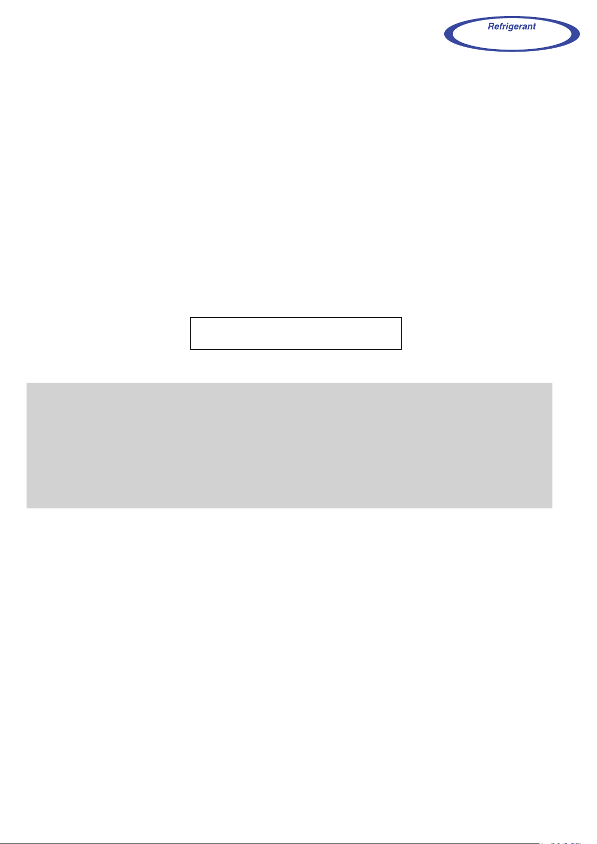
1. WALL MOUNTED
TYPE :
ASWA09LCC
ASWA12LCC
ASWA18LCC
INDOOR UNIT
Page 2
- (01 - 01) -
WALL MOUNTED TYPE
ASWA09-18LC
WALL MOUNTED TYPE
ASWA09-18LC
MODEL :
ASWA09LCC
ASWA12LCC
ASWA18LCC
FEATURES
1. FEATURE
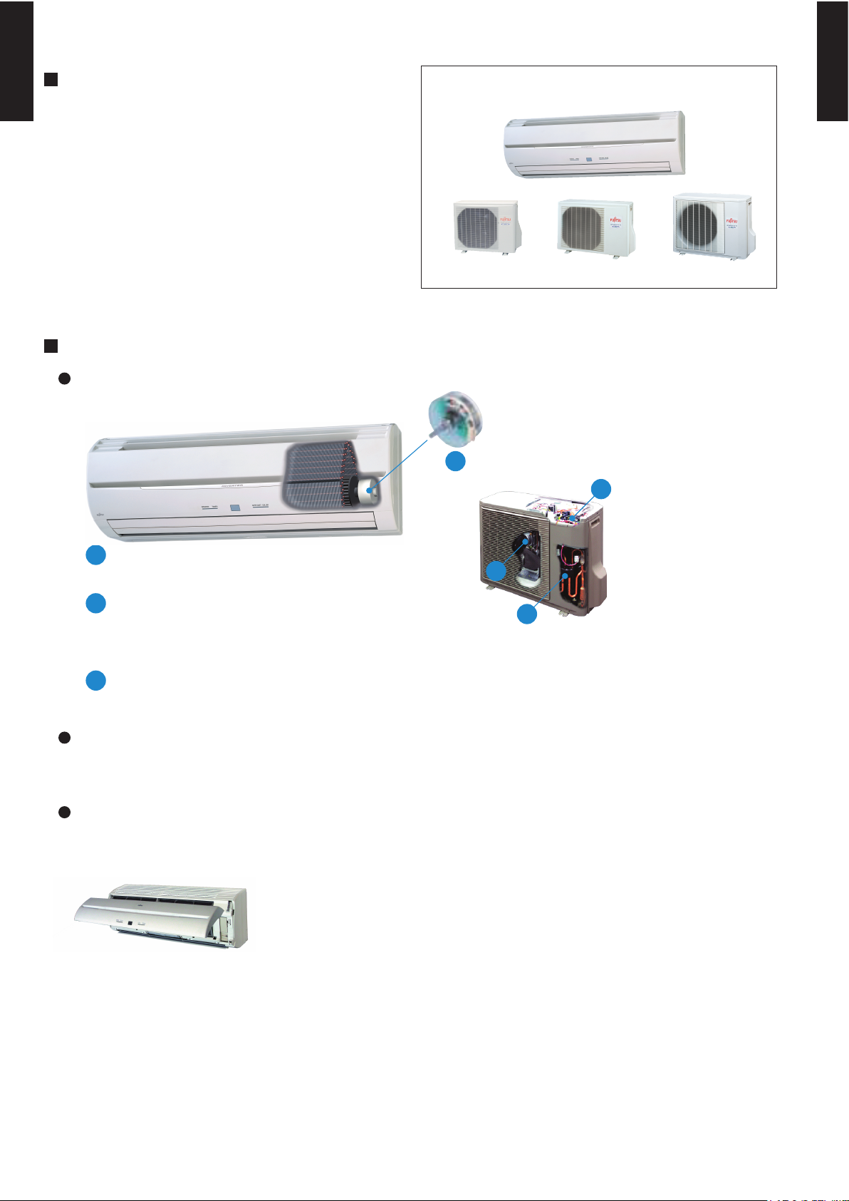
Super quiet
ALL DC (18TYPE)
When operation starts, the machine operates at high voltage and high power
and when operation stabilizes, the set temperature is maintained at low voltage.
Indoor unit : ALL TYPE
Outdoor unit : 18TYPE
Front view
Air flow mode can be set in 4 steps and more detailed air flow setting is possible.
Easy maintenance
Easy maintenance and always clean. Troublesome maintenance has been made easy.
Since the front panel is easy to remove, maintenance is also easy.
i-PAM control (09TYPE)
V-PAM technology makes a compressor more powerful.
V-PAM control (12 / 18TYPE)
b
DC rotary compressor
c
a
DC fan motor
b
a
a
c
(AOWR12LC) (AOWR18LC)(AOWR09LC)
Page 3
- (01 - 02) -
WALL MOUNTED TYPE
ASWA09-18LC
WALL MOUNTED TYPE
ASWA09-18LC
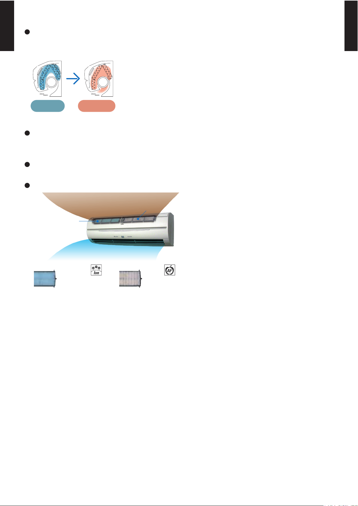
Inner drying operation
This model is equipped with an inner drying function. After the power is turned off, the dry operation
starts inside the air conditioner. This prevents the growth of mold and bacteria inside the air conditioner.
During dew
condensation
Approx. 20 mins
Drying
Low outdoor air temperature cooling correspondence (18TYPE)
Corresponds to cooling operation at -10
°C
outdoor air temperature
Corresponds to maximum 20m long piping
Applecatechin Filter
Long-life Ion
Deodorization Filter
Air conditioner filter features
Ion Deodorization
Filter
Apple-catechin Filter
Dirty Air
Clean Air
Page 4
- (01 - 03) -
WALL MOUNTED TYPE
ASWA09-18LC
WALL MOUNTED TYPE
ASWA09-18LC
FEATURES
Four kinds of timer setup (ON / OFF / PROGRAM / SLEEP) are possible.
Four kinds of timers. Easy operation.
Select from four different timer programs (On/Off/Program/Sleep).
Built-in timers
The program timer operates the ON and OFF timer once within a 24 hour period.
Program timer
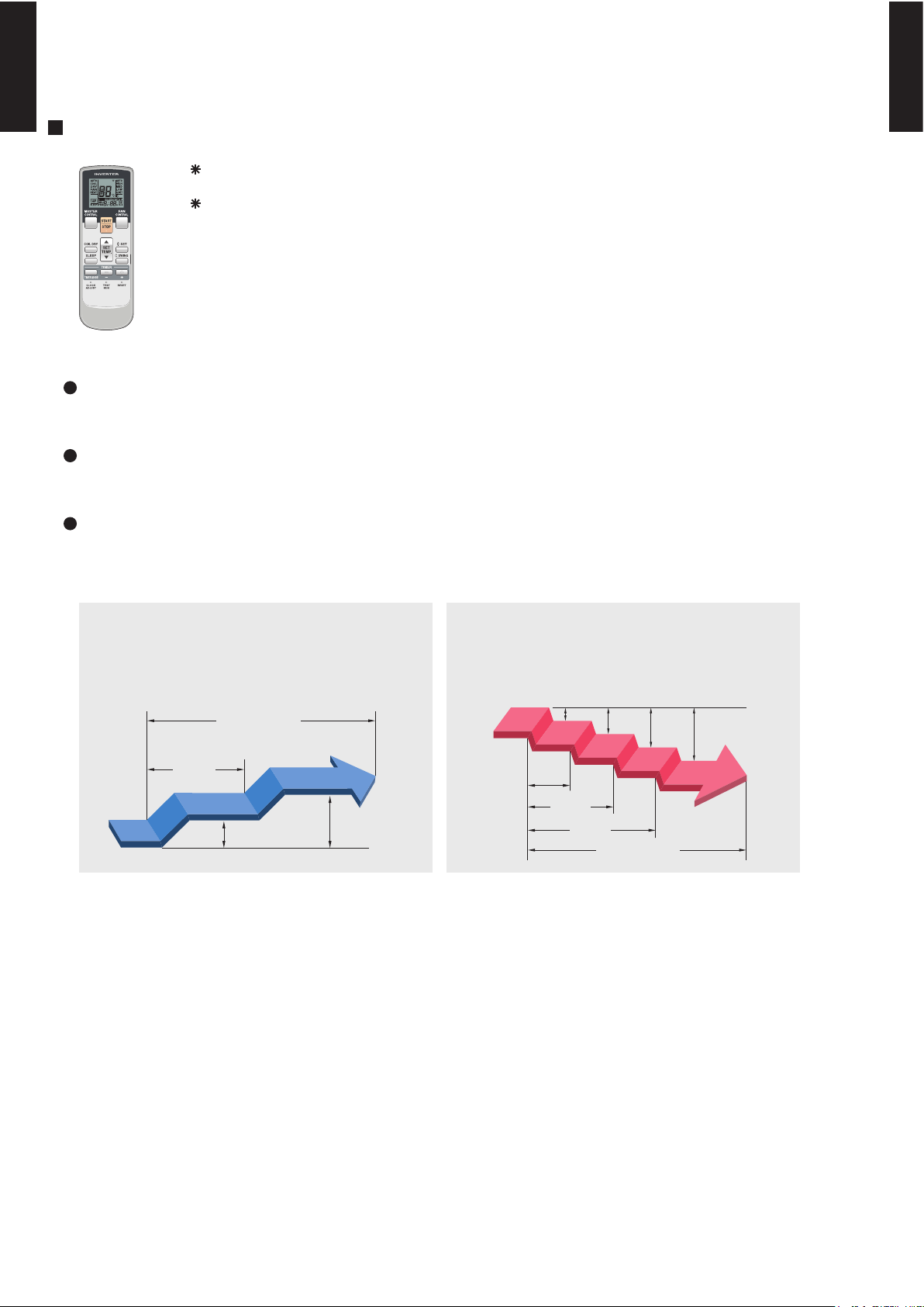
The sleep timer function automatically corrects the temperature thermostat setting according to the
time setting to prevent excessive cooling and heating while sleeping.
Sleep timer
2-1. WIRELESS REMOTE CONTROLLER
2.
REMOTE CONTROLLER
Cooling operation/dry operation
60min.
1 °C
2 °C
When the sleep timer is set, the set temperature
automatically rises 1 °C every hour. The set
temperature can rise up to a maximum of 2 °C.
Heating operation
When the sleep timer is set, the set temperature
automatically drops 1 °C every 30 minutes. The
set temperature can drop to a maximum of 4 °C.
1 °C
30min.
60min.
90min.
2 °C
3 °C
4 °C
Timer setting
Timer setting
Page 5
- (01 - 04) -
WALL MOUNTED TYPE
ASWA09-18LC
WALL MOUNTED TYPE
ASWA09-18LC
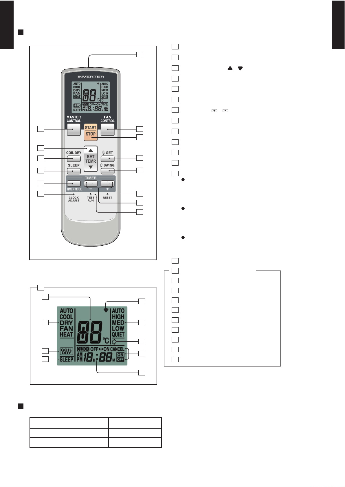
Display panel
FUNCTIONS
SPECIFICATION
SIZE (H x W x D mm) 176 x 56 x 18
WEIGHT ( g ) 110
ACCESSORY Holder
TIMER SET ( / ) button
TEST RUN button
This button is used when installing the
conditioner, and should not be used under normal conditions, as it will cause the
air conditioner’s thermostat function to operate incorrectly.
If this button is pressed during normal operation, the unit will switch to test operation mode, and the Indoor Unit’s OPERATION Indicator Lamp and TIMER Indicator
Lamp will begin to flash simultaneously.
To stop the test operation mode, press the
START/STOP button to stop the air conditioner.
CLOCK ADJUST button
Remote Control Unit Display
Transmit Indicator
Clock Display
Operating Mode Display
Timer Mode Display
Fan Speed Display
Temperature SET Display
SLEEP button
MASTER CONTROL button
/ )
SET TEMP. button (
COIL DRY button
Signal Transmitter
TIMER MODE button
FAN CONTROL button
START/STOP button
SET button (Vertical)
SWING button
RESET button
COIL DRY Display
SLEEP Display
SWING Display
4
5
6
7
8
9
17
19
20
21
22
23
24
18
16
2
3
10
12
11
14
15
1
13
2
4
9
3
1
14
5
16
17
18
20
23
22
21
24
12
10
11
13
8
7
6
19
15
Page 6
- (01 - 05) -
WALL MOUNTED TYPE
ASWA09-18LC
WALL MOUNTED TYPE
ASWA09-18LC
3. SPECIFICATIONS
ASWA09LCC ASWA12LCC
1 1
kW 2.60 3.50
BTU/h 8,900 11,900
kW 0.5 - 3.6 0.9 - 4.3
BTU/h 1,700 -12,300 3,100 - 14,700
kW 3.60 4.80
BTU/h 12,300 16,400
kW 0.5 - 5.3 0.9 - 6.7
BTU/h 1,700 - 18,100 3,100 - 22,900
0.67 0.93
0.25 - 1.18 0.25 - 1.61
0.845 1.25
0.25 - 1.96 0.25 - 2.30
3.4 4.5
6.0 7.0
4.1 5.9
8.5 10.0
3.88 3.76
4.26 3.84
kW 1.70 2.30
90 94
94 96
l/h (pints/h) 1.3 (2.7) 1.8 (3.8)
High 595 635
Med 500 515
Low 410 410
Quiet 290 290
High 645 670
Med 540 540
Low 435 435
Quiet 320 320
W 24 24
High 41 42
Med 36 36
Low 30 30
Quiet 21 21
High 41 42
Med 36 35
Low 30 29
Quiet 21 21
Dimensions (H × W × D)
°C
%RH
°C
mm
Note :
Specifications are based on the following conditions.
Cooling : Indoor temperature of 27°CDB/19°CWB. and outdoor temperature of 35°CDB/24°CWB.
Heating : Indoor temperature of 20°CDB/15°CWB. and outdoor temperature of 7°CDB/6°CWB.
Pipe length : 7.5 m, Height difference : 0 m. (Outdoor unit - Indoor unit)
The maximum current is the maximum value when operated within the operation range(temperature).
Outer diameter : 29 / Inner diameter : 13.6
Operation range
kg(lb.)
Connection pipe
Size
mm
Remote controller type
Drain pipe
Material
Fin pitch
Rows × Stages
Pipe type
Fin type
Weight
Heat exchanger type
Enclosure
Dimensions
(H × W × D)
kW/kW
Cooling
Heating
%
Cooling
Heating
Cooling
Current
Cooling
SENSIBLE CAPACITY
POWER FACTOR
A
Heating
Rated
Max
Rated
Max
Input power
Cooling
kW
Heating
Rated
Min-Max
Type
mm
Rated
Min-Max
Rated
Min-Max
Rated
Min-Max
Type × Q'ty
Motor output
Cross flow fan × 1
Cooling
Heating
Noise level
dB(A)
Fan
Airflow
rate
Cooling
Heating
m3/h
WALL MOUNTED
INVERTER HEAT PUMP
220V 50Hz
198 - 242V 50Hz
336 × 635 × 26.6
1.2
2×16
Copper
Aluminium
Polystyrene
White
275 × 790 × 215
290 × 835 × 345
9 (19.8)
12 (16.5)
6.35 ( 1/4 in.)
30 or less
Wireless
PP+LLDPE
9.52 ( 3/8 in.)
Flare
18 to 32
80 or less
Model name
EER
COP
Moisture removal
Power source
Available voltage range
Capacity
Cooling
Heating
ENERGY GRADE
Material
Colour
Net
Gross
mm
Net
Gross
Liquid
Gas
Method
Cooling
Heating
Size
Page 7
- (01 - 06) -
WALL MOUNTED TYPE
ASWA09-18LC
WALL MOUNTED TYPE
ASWA09-18LC
WALL MOUNTED
INVERTER HEAT PUMP
ASWA18LCC
220V 50Hz
198 - 242V 50Hz
2
kW 5.20
BTU/h 17,700
kW 0.9 - 5.7
BTU/h 3,100 - 19,400
kW 6.25
BTU/h 21,300
kW 0.9 - 9.1
BTU/h 3,100 - 31,000
1.72
0.09 - 2.00
1.73
0.09 - 2.66
7.9
9.0
8.0
13.5
3.02
3.61
kW 3.30
99
98
l/h (pints/h) 2.8 (5.9)
High 700
Med 580
Low 460
Quiet 370
High 700
Med 600
Low 500
Quiet 420
Cross flow fan × 1
W 24
High 44
Med 38
Low 32
Quiet 25
High 42
Med 37
Low 32
Quiet 27
MAIN : 336 × 635 × 26.6
SUB : 84 × 635 × 13.3
Main : 1.2 / Sub : 1.4
Main : 2 × 16, Sub : 1 × 4
Copper
Aluminium
Polystyrene
White
275 × 790 × 215
290 × 835 × 345
9 (20)
12 (26)
6.35 ( 1/4 in.)
12.7 ( 1/2 in.)
Flare
°C 18 to 32
%RH 80 or less
°C 30 or less
Wireless
PP+LLDPE
mm Outer diameter : 29 / Inner diameter : 13.6
Note :
Specifications are based on the following conditions.
Cooling : Indoor temperature of 27°CDB/19°CWB. and outdoor temperature of 35°CDB/24°CWB.
Heating : Indoor temperature of 20°CDB/15°CWB. and outdoor temperature of 7°CDB/6°CWB.
Pipe length : 7.5 m, Height difference : 0 m. (Outdoor unit - Indoor unit)
The maximum current is the maximum value when operated within the operation range(temperature).
Cooling
Heating
Size
Gross
Liquid
Gas
Method
Colour
Net
Gross
Net
Model name
EER
COP
Moisture removal
Cooling
Heating
Noise level
dB(A)
Type
mm
Rated
Min-Max
Rated
Min-Max
Rated
Min-Max
Power source
Available voltage range
Capacity
Cooling
Heating
ENERGY GRADE
Input power
Cooling
kW
Heating
Rated
Min-Max
A
Heating
Rated
Max
Rated
Max
Fan
Airflow
rate
Current
Cooling
SENSIBLE CAPACITY
POWER FACTOR
Type × Q'ty
Motor output
kW/kW
Cooling
Heating
%
Cooling
Heating
Cooling
mm
Weight
Heat exchanger type
Enclosure
Dimensions (H × W × D)
Fin pitch
Rows × Stages
Pipe type
Fin type
Material
Remote controller type
Drain pipe
Material
Cooling
Heating
m3/h
Operation range
kg(lb.)
Connection pipe
Size
mm
Dimensions
(H × W × D)
Page 8
- (01 - 07) -
WALL MOUNTED TYPE
ASWA09-18LC
WALL MOUNTED TYPE
ASWA09-18LC
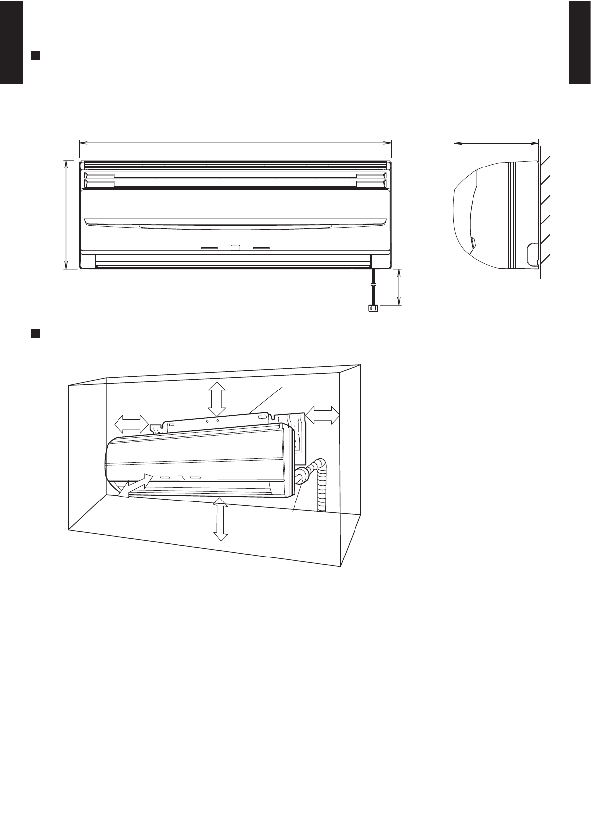
4. DIMENSIONS
MODEL : ASWA09LC, ASWA12LC, ASWA18LC
(Unit : mm)
INSTALLATION PLACE
275
2,000
215
790
6 cm or more
Wall hook bracket
5 cm or more
9 cm or more
150 cm or more
(Wall cap)
230 cm or more
Page 9
- (01 - 08) -
WALL MOUNTED TYPE
ASWA09-18LC
WALL MOUNTED TYPE
ASWA09-18LC
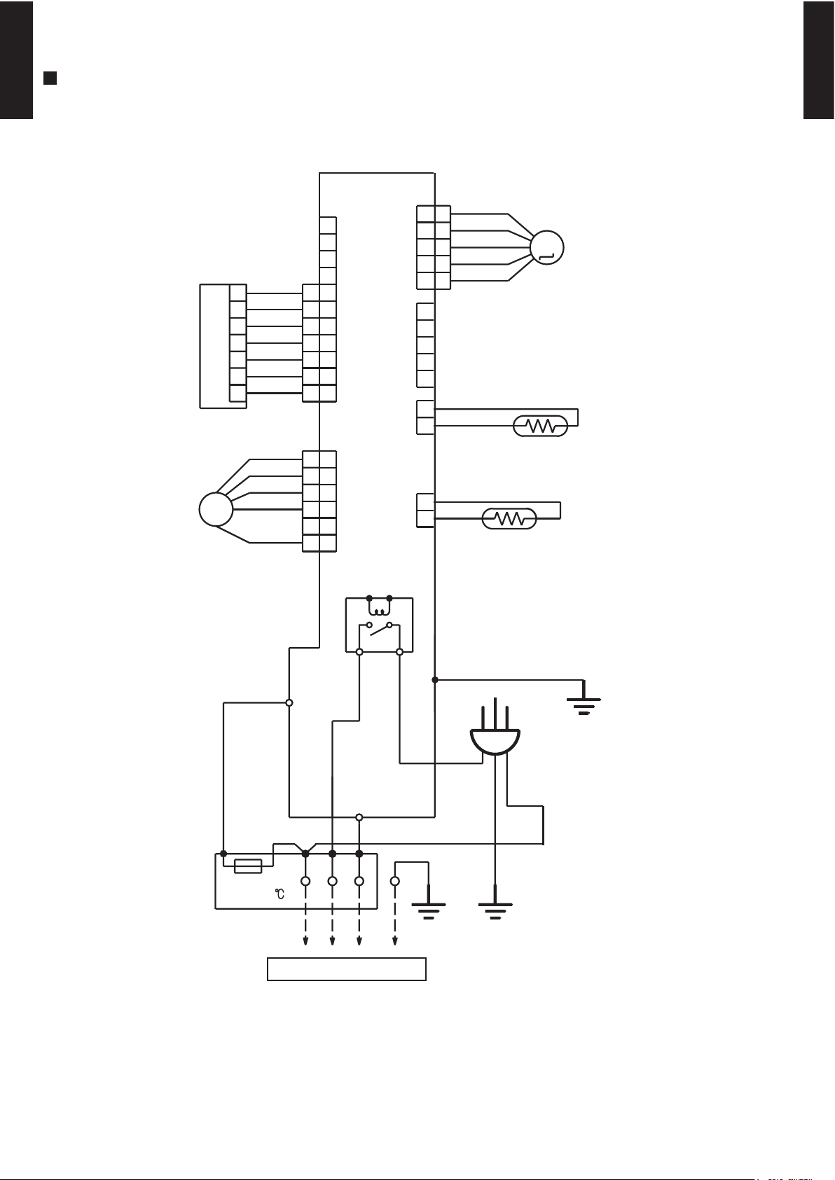
5. WIRING DIAGRAMS
MODEL : ASWA09LC, ASWA12LC, ASWA18LC
POWER RELAY
3 4
TM1
W3
TM2
CN2
CN4 CN5
CN7
CN6
CN3
CN201
TERMINAL
POWER SOURCE
FAN MOTOR
ROOM TEMPERATURE THERMISTOR
PIPE TEMPERATURE THERMISTOR
STEP MOTOR
1
10
11
2
3
4
5
6
7
8
9
1
2
3
4
5
6
7
1
2
3
4
5
6
7
1
2
3
4
5
6
1
2
3
4
5
6
1
2
3
4
5
1
2
3
4
5
1
2
3
4
5
1
2
1
2
ORANGE
YELLOW
PINK
BLUE
RED
BLACK
BLACK
GREEN
WHITE
BLUE
RED
BROWN
BLACK
GREEN / YELLOW
N
L
3
THERMAL
FUSE 102
WHITE
YELLOW
BLACK
RED
BLUE
WHITE
WHITE
WHITE
WHITE
WHITE
WHITE
RED
BLACK or GRAY
BLACK or GRAY
F M
INDICATOR PCB
CONTROLLER PCB
TO OUTDOOR UNIT
TEST
M
L
N
Page 10
- (01 - 09) -
WALL MOUNTED TYPE
ASWA09-18LC
WALL MOUNTED TYPE
ASWA09-18LC
6. CAPACITY TABLE
6-1. COOLING CAPACITY
MODEL : ASWA09LC
MODEL : ASWA12LC
MODEL : ASWA18LC
AFR : Air Flow Rate (m3/min)
TC : Total Capacity (kW)
SHC : Sensible Heat Capacity (kW)
PI : Power Input (kW)
°CDB
°CWB
TC SHC PI TC SHC PI TC SHC PI TC SHC PI TC SHC PI TC SHC PI TC SHC PI
3.85 2.61 0.82 4.29 2.63 0.83 4.44 2.86 0.84 4.73 2.86 0.84 4.87 3.09 0.85 5.17 3.08 0.86 5.46 3.28 0.87
4.59 3.11 1.36 5.11 3.13 1.38 5.29 3.40 1.39 5.63 3.41 1.40 5.81 3.69 1.41 6.16 3.67 1.43 6.51 3.91 1.44
4.39 2.98 1.51 4.89 3.00 1.53 5.06 3.26 1.54 5.39 3.27 1.56 5.56 3.53 1.56 5.89 3.51 1.58 6.23 3.74 1.59
4.11 2.79 1.66 4.58 2.80 1.69 4.73 3.05 1.69 5.04 3.06 1.71 5.20 3.30 1.72 5.51 3.29 1.74 5.82 3.50 1.75
3.71 2.51 1.67 4.13 2.53 1.70 4.27 2.75 1.70 4.55 2.76 1.72 4.69 2.98 1.73 4.98 2.97 1.75 5.26 3.16 1.77
3.47 2.35 1.68 3.86 2.36 1.71 3.99 2.57 1.72 4.26 2.58 1.74 4.39 2.78 1.75 4.65 2.77 1.76 4.91 2.95 1.78
AFR
11.7
43
25
30
35
40
Indoor temperature
Outdoor temperature
12
15
°CDB
20
232518
21
16
18
272932
231921
°CDB
°CWB
TC SHC PI TC SHC PI TC SHC PI TC SHC PI TC SHC PI TC SHC PI TC SHC PI
2.59 1.82 0.44 2.89 1.83 0.45 2.99 1.99 0.45 3.18 2.00 0.46 3.28 2.16 0.46 3.48 2.15 0.46 3.67 2.29 0.47
3.09 2.17 0.74 3.44 2.18 0.75 3.56 2.37 0.75 3.79 2.38 0.76 3.91 2.57 0.76 4.14 2.56 0.77 4.38 2.73 0.78
2.96 2.08 0.82 3.29 2.09 0.83 3.41 2.27 0.83 3.63 2.28 0.84 3.74 2.46 0.85 3.97 2.45 0.85 4.19 2.61 0.86
2.77 1.94 0.90 3.08 1.95 0.91 3.19 2.12 0.92 3.40 2.13 0.93 3.50 2.30 0.93 3.71 2.29 0.94 3.92 2.44 0.95
2.50 1.75 0.90 2.78 1.76 0.92 2.87 1.92 0.92 3.06 1.92 0.93 3.16 2.08 0.94 3.35 2.07 0.95 3.54 2.20 0.95
2.33 1.64 0.91 2.60 1.65 0.92 2.69 1.79 0.93 2.86 1.80 0.94 2.95 1.94 0.94 3.13 1.93 0.95 3.31 2.06 0.96
16
18
272932
231921
232518
21
20
12
15
°CDB
AFR
10.6
43
25
30
35
40
Indoor temperature
Outdoor temperature
°CDB
°CWB
TC SHC PI TC SHC PI TC SHC PI TC SHC PI TC SHC PI TC SHC PI TC SHC PI
1.93 1.34 0.32 2.14 1.35 0.32 2.22 1.47 0.33 2.36 1.48 0.33 2.44 1.59 0.33 2.58 1.59 0.33 2.73 1.69 0.34
2.29 1.60 0.53 2.56 1.61 0.54 2.64 1.75 0.54 2.82 1.76 0.55 2.90 1.90 0.55 3.08 1.89 0.56 3.25 2.01 0.56
2.20 1.53 0.59 2.45 1.54 0.60 2.53 1.68 0.60 2.70 1.68 0.61 2.78 1.82 0.61 2.95 1.81 0.62 3.11 1.93 0.62
2.05 1.43 0.65 2.29 1.44 0.66 2.37 1.57 0.66 2.52 1.57 0.67 2.60 1.70 0.67 2.76 1.69 0.68 2.91 1.80 0.68
1.85 1.30 0.65 2.07 1.30 0.66 2.14 1.42 0.66 2.28 1.42 0.67 2.35 1.53 0.67 2.49 1.53 0.68 2.63 1.63 0.69
1.73 1.21 0.66 1.93 1.22 0.67 2.00 1.32 0.67 2.13 1.33 0.68 2.19 1.43 0.68 2.33 1.43 0.69 2.46 1.52 0.69
AFR
9.9
43
25
30
35
40
Indoor temperature
Outdoor temperature
12
15
°CDB
20
232518
21
16
18
272932
231921
Page 11
- (01 - 10) -
WALL MOUNTED TYPE
ASWA09-18LC
WALL MOUNTED TYPE
ASWA09-18LC
6-2. HEATING CAPACITY
MODEL : ASWA09LC
MODEL : ASWA18LC
AFR : Air Flow Rate (m3/min)
TC : Total Capacity (kW)
PI : Power Input (kW)
TC PI TC PI TC PI TC PI TC PI
5.09 2.01 4.97 2.05 4.84 2.09 4.72 2.13 4.60 2.17
6.04 2.19 5.90 2.24 5.75 2.29 5.61 2.33 5.46 2.38
6.80 2.31 6.64 2.35 6.48 2.40 6.32 2.45 6.15 2.50
7.86 2.46 7.67 2.51 7.48 2.57 7.30 2.62 7.11 2.67
8.94 2.63 8.72 2.69 8.51 2.74 8.30 2.80 8.09 2.85
9.56 2.55 9.33 2.61 9.10 2.66 8.87 2.71 8.65 2.77
9.90 2.56 9.66 2.61 9.43 2.66 9.19 2.72 8.96 2.77
9.58 2.22 9.35 2.27 9.13 2.31 8.90 2.36 8.67 2.41
AFR
°CDB
11.7
-16
-11
-7
Outdoor temperature
15
10
6
0
-2
7
385
10
°CDB
°CWB
-15
24
-10
Indoor temperature
-5
161820
22
MODEL : ASWA12LC
TC PI TC PI TC PI TC PI TC PI
2.96 1.48 2.89 1.51 2.82 1.54 2.75 1.57 2.68 1.60
3.52 1.62 3.43 1.65 3.35 1.68 3.27 1.72 3.18 1.75
3.96 1.70 3.87 1.74 3.77 1.77 3.68 1.81 3.58 1.84
4.58 1.82 4.47 1.85 4.36 1.89 4.25 1.93 4.14 1.97
5.21 1.94 5.08 1.98 4.96 2.02 4.83 2.06 4.71 2.10
5.57 1.88 5.43 1.92 5.30 1.96 5.17 2.00 5.04 2.04
5.76 1.88 5.63 1.92 5.49 1.96 5.35 2.00 5.22 2.04
5.58 1.64 5.45 1.67 5.32 1.71 5.18 1.74 5.05 1.77
AFR
°CDB
9.9
-16
-11
-7
Outdoor temperature
15
10
60-2
7
385
10
°CDB
°CWB
-15
24
-10
Indoor temperature
-5
161820
22
TC PI TC PI TC PI TC PI TC PI
3.75 1.73 3.66 1.77 3.57 1.81 3.48 1.84 3.39 1.88
4.45 1.90 4.34 1.94 4.24 1.98 4.13 2.02 4.02 2.06
5.01 1.99 4.89 2.04 4.77 2.08 4.65 2.12 4.53 2.16
5.79 2.13 5.65 2.17 5.51 2.22 5.37 2.26 5.23 2.31
6.58 2.27 6.42 2.32 6.27 2.37 6.11 2.42 5.95 2.46
7.04 2.21 6.87 2.25 6.70 2.30 6.53 2.35 6.37 2.39
7.29 2.21 7.11 2.26 6.94 2.30 6.77 2.35 6.59 2.39
7.06 1.92 6.89 1.96 6.72 2.00 6.55 2.04 6.38 2.08
-10
Indoor temperature
-5
161820
22
°CDB
°CWB
-15
24
0
-2
7
385
10
15
10
6
°CDB
10.6
-16
-11
-7
Outdoor temperature
AFR
Page 12
- (01 - 11) -
WALL MOUNTED TYPE
ASWA09-18LC
WALL MOUNTED TYPE
ASWA09-18LC
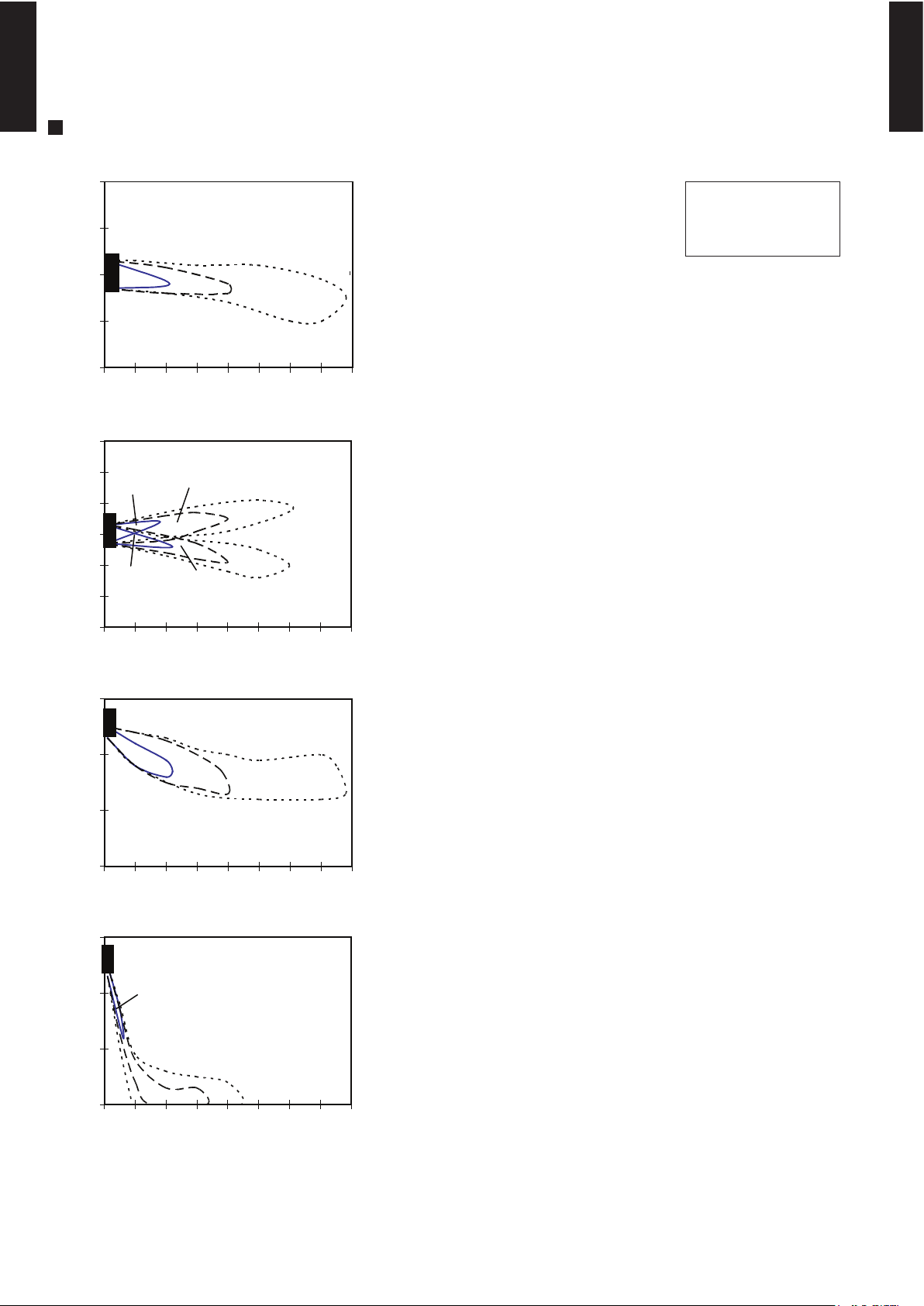
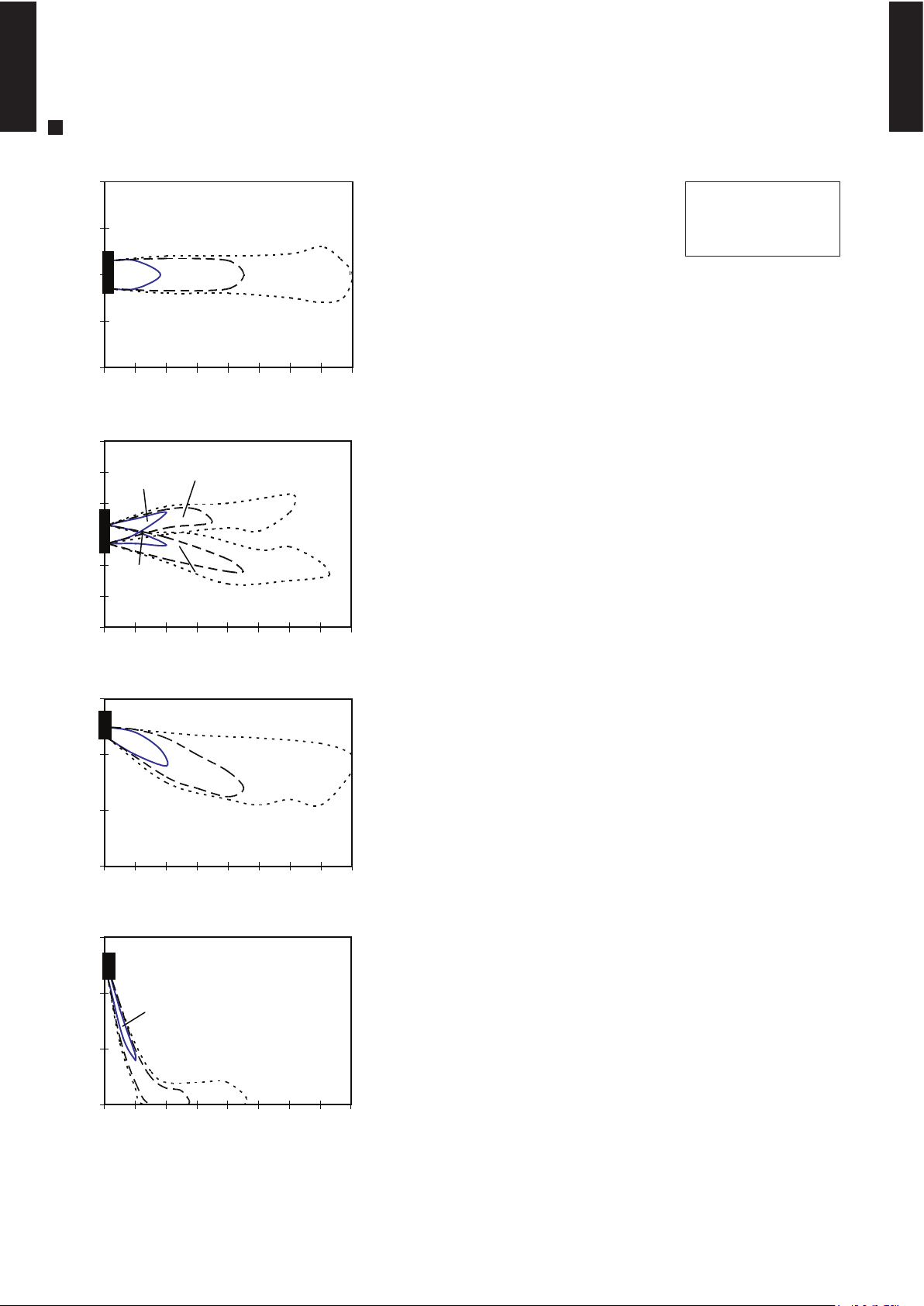
7. FAN PERFORMANCE
7-1. AIR VELOCITY DISTRIBUTION
MODEL : ASWA09LC
Note :
Fan speed : High
Voltage : 220V
Unit : m/s
Unit : m/s
Unit : m/s
Unit : m/s
TOP VIEW
FLOW CONTROL PANEL : Horiz.
LOUVER : Center
TOP VIEW
FLOW CONTROL PANEL : Horiz.
LOUVER : Right & Left
SIDE VIEW
FLOW CONTROL PANEL : Horiz.
LOUVER : Center
SIDE VIEW
FLOW CONTROL PANEL : Vert.
LOUVER : Center
(m)
(m)
(m)
(m)
(m)
(m)
(m)
(m)
Operation mode :FAN
1
765
43
2 8
1 765432 8
3
2
1
0
1
2
3
2
1
0
1
2
0
1
2
3
1
765
43
2 8
0
1
2
3
1
0
0
0
0
765
43
2 8
2.0
1.0
0.5
0.5
1.0
1.0
2.0
2.0
0.5
2.0
1.0
0.5
2.0
1.0
0.5
Page 13
- (01 - 12) -
WALL MOUNTED TYPE
ASWA09-18LC
WALL MOUNTED TYPE
ASWA09-18LC
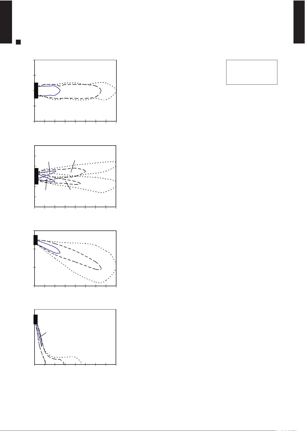
MODEL : ASWA12LC
Note :
Fan speed : High
Voltage : 220V
Unit : m/s
Unit : m/s
Unit : m/s
Unit : m/s
TOP VIEW
FLOW CONTROL PANEL : Horiz.
LOUVER : Center
TOP VIEW
FLOW CONTROL PANEL : Horiz.
LOUVER : Right & Left
SIDE VIEW
FLOW CONTROL PANEL : Horiz.
LOUVER : Center
SIDE VIEW
FLOW CONTROL PANEL : Vert.
LOUVER : Center
(m)
(m)
(m)
(m)
(m)
(m)
(m)
(m)
Operation mode :FAN
1
765
43
2 8
1 765432 8
3
2
1
0
1
2
3
2
1
0
1
2
0
1
2
3
1
765
43
2 8
0
1
2
3
1
0
0
0
0
765
43
2 8
2.0
1.0 0.5
0.5
1.0
1.0
2.0
2.0
0.5
2.0
1.0 0.5
2.0
1.0
0.5
Page 14
- (01 - 13) -
WALL MOUNTED TYPE
ASWA09-18LC
WALL MOUNTED TYPE
ASWA09-18LC
MODEL : ASWA18LC
Note :
Fan speed : High
Voltage : 220V
Unit : m/s
Unit : m/s
Unit : m/s
Unit : m/s
TOP VIEW
FLOW CONTROL PANEL : Horiz.
LOUVER : Center
TOP VIEW
FLOW CONTROL PANEL : Horiz.
LOUVER : Right & Left
SIDE VIEW
FLOW CONTROL PANEL : Horiz.
LOUVER : Center
SIDE VIEW
FLOW CONTROL PANEL : Vert.
LOUVER : Center
(m)
(m)
(m)
(m)
(m)
(m)
(m)
(m)
Operation mode :FAN
1
765
43
2 8
1 765432 8
3
2
1
0
1
2
3
2
1
0
1
2
0
1
2
3
1
765
43
2 8
0
1
2
3
1
0
0
0
0
765
43
2 8
2.0
1.0
0.5
0.5
0.5
1.0
1.0
2.0
2.0
2.0
1.0 0.5
2.0
1.0
0.5
Page 15

- (01 - 14) -
WALL MOUNTED TYPE
ASWA09-18LC
WALL MOUNTED TYPE
ASWA09-18LC
MODEL : ASWA09LC
COOLING
7-2. AIR FLOW
HEATING
595
m3/h
165 l/s
350 CFM
500
m3/h
139 l/s
294 CFM
410
m3/h
114 l/s
241 CFM
290
m3/h
81 l/s
171 CFM
Airflow
Fan speed
Number of
rotations
(r.p.m)
HIGH
MED
LOW
QUIET
1300
1120
950
700
645
m3/h
179 l/s
380 CFM
540
m3/h
150 l/s
318 CFM
435
m3/h
121 l/s
256 CFM
320
m3/h
89 l/s
188 CFM
Airflow
HIGH
MED
LOW
QUIET
Fan speed
Number of
rotations
(r.p.m)
1390
1200
1000
760
Page 16

- (01 - 15) -
WALL MOUNTED TYPE
ASWA09-18LC
WALL MOUNTED TYPE
ASWA09-18LC
MODEL : ASWA12LC
COOLING
HEATING
635
m3/h
176 l/s
374 CFM
515
m3/h
143 l/s
303 CFM
410
m3/h
114 l/s
241 CFM
290
m3/h
81 l/s
171 CFM
Fan speed
HIGH
MED
Airflow
LOW
QUIET
1370
Number of
rotations
(r.p.m)
1150
950
700
670
m3/h
186 l/s
394 CFM
540
m3/h
150 l/s
318 CFM
435
m3/h
121 l/s
256 CFM
320
m3/h
89 l/s
188 CFM
Airflow
Number of
rotations
(r.p.m)
Fan speed
HIGH
MED
LOW
QUIET
1440
1200
1000
760
Page 17

- (01 - 16) -
WALL MOUNTED TYPE
ASWA09-18LC
WALL MOUNTED TYPE
ASWA09-18LC
MODEL : ASWA18LC
COOLING
HEATING
700
m3/h
700
m3/h
194 l/s
194 l/s
412 CFM
412 CFM
580
m3/h
600
m3/h
161 l/s
167 l/s
341 CFM
353 CFM
460
m3/h
500
m3/h
128 l/s
139 l/s
271 CFM
294 CFM
370
m3/h
420
m3/h
103 l/s
117 l/s
218 CFM
247 CFM
LOW
1110
QUIET
950
HIGH
1480
MED
1300
1480
1260
1040
850
HIGH
MED
LOW
QUIET
Air flow
Air flow
Fan speed
Number of
rotations
(r.p.m)
Fan speed
Number of
rotations
(r.p.m)
Page 18

- (01 - 17) -
WALL MOUNTED TYPE
ASWA09-18LC
WALL MOUNTED TYPE
ASWA09-18LC
8-1. NOISE LEVEL CURVE
8. OPERATION NOISE
COOLING
Octave band sound pressure level, dB:(0dB=0.0002µbar)
Octave band center frequency,Hz
0
10
20
30
40
50
60
70
80
Octave band sound pressure level, dB:(0dB=0.0002µbar)
0
10
20
30
40
50
60
70
80
63 125 250 500 1,000 2,000 4,000 8,000
Octave band center frequency,Hz
63 125 250 500 1,000 2,000 4,000 8,000
COOLING
Octave band sound pressure level, dB:(0dB=0.0002µbar)
Octave band center frequency,Hz
0
10
20
30
40
50
60
70
80
63 125 250 500 1,000 2,000 4,000 8,000
HEATING
MODEL : ASWA09LC
MODEL : ASWA12LC
Octave band sound pressure level, dB:(0dB=0.0002µbar)
Octave band center frequency,Hz
0
10
20
30
40
50
60
70
80
63 125 250 500 1,000 2,000 4,000 8,000
HEATING
High
Quiet
High
Quiet
High
Quiet
NC-20
NC-40
NC-50
NC-60
NC-30
NC-15
NC-25
NC-35
NC-45
NC-55
NC-65
NC-20
NC-40
NC-50
NC-60
NC-30
NC-15
NC-25
NC-35
NC-45
NC-55
NC-65
NC-20
NC-40
NC-50
NC-60
NC-30
NC-15
NC-25
NC-35
NC-45
NC-55
NC-65
High
Quiet
NC-20
NC-40
NC-50
NC-60
NC-30
NC-15
NC-25
NC-35
NC-45
NC-55
NC-65
Page 19

- (01 - 18) -
WALL MOUNTED TYPE
ASWA09-18LC
WALL MOUNTED TYPE
ASWA09-18LC
COOLING
MODEL : ASWA18LC
HEATING
Octave band sound pressure level, dB:(0dB=0.0002µbar)
Octave band center frequency,Hz
0
10
20
30
40
50
60
70
80
63 125 250 500 1,000 2,000 4,000 8,000
High
Quiet
NC-20
NC-40
NC-50
NC-60
NC-30
NC-15
NC-25
NC-35
NC-45
NC-55
NC-65
Octave band sound pressure level, dB:(0dB=0.0002µbar)
Octave band center frequency,Hz
0
10
20
30
40
50
60
70
80
63 125 250 500 1,000 2,000 4,000 8,000
High
Quiet
NC-20
NC-40
NC-50
NC-60
NC-30
NC-15
NC-25
NC-35
NC-45
NC-55
NC-65
Page 20

- (01 - 19) -
WALL MOUNTED TYPE
ASWA09-18LC
WALL MOUNTED TYPE
ASWA09-18LC
8-2.
SOUND LEVEL CHECK POINT
Page 21

- (01 - 20) -
WALL MOUNTED TYPE
ASWA09-18LC
WALL MOUNTED TYPE
ASWA09-18LC
9. ELECTRIC CHARACTERISTICS
ASWA09LC ASWA12LC ASWA18LC
Voltage V
Frequency Hz
A 8.5 10.0 13.5
Circuit breaker A 15 20 20
Connection Cable
mm
2
1.5 - 2.5 1.5 - 2.5 2 - 3.5
Limited wiring length m
220
50
21
Model Name
Max Operating Current
*1)Wiring Spec.
Power Supply
*1) Wiring Spec.
Selected Sample
(Selected based on Japan Electrotechnical Standard and Codes Committee E0005)
Page 22

- (01 - 21) -
WALL MOUNTED TYPE
ASWA09-18LC
WALL MOUNTED TYPE
ASWA09-18LC
10. SAFETY DEVICES
ASWA09LC ASWA12LC ASWA18LC
Circuit protection Current fuse (PCB)
Terminal protection Current (thermal) fuse
Fan motor protection Thermal protection program
3A 250V 102°C
100
+15
-10
°C OFF
95
+5
-10
°C ON
Protection form
Model
3.15A 250V
Page 23

- (01 - 22) -
WALL MOUNTED TYPE
ASWA09-18LC
WALL MOUNTED TYPE
ASWA09-18LC
11. OPTIONAL PARTS
Exterior Summary
Parts name
Apple-catechin
filter
Ion deodorisation
filter
Model No.
UTR-FA03-2
UTR-FA03-3
Fine dust, invisible mold spores,
and harmful microorganisms
are absorbed onto the filter by
static electricity, and further
growth is inhibited and
deactivated by the polyphenol
ingredient extracted from
apples.
The filter deodorizes by
powerfully decomposing
absorbed odors using the
oxidizing and reducing effects
of ions generated by the ultra
fine-particle ceramic.
Page 24

R410A
D1D_AO010E/02
2007.11.15
AOWR09LCC
AOWR12LCC
AOWR18LCC
2. SINGLE
TYPE :
OUTDOOR UNIT
Page 25

- (02 - 01) -
OUTDOOR UNIT
AOWR09-18LC
OUTDOOR UNIT
AOWR09-18LC
1. SPECIFICATIONS
AOWR09LCC AOWR12LCC
A 4.1 5.9
1,820 1,835
1,820 1,835
W 26 26
47 47
48 49
508 × 690 × 22 504 × 850 × 36.4
1.3 1.4
1 × 20 2 × 24
W
g 900 1,050
540 × 660 × 290 540 × 790 × 290
611 × 797 × 401 648 × 910 × 380
32 (70) 37 (82)
35 (77) 41 (90)
Note :
Specifications are based on the following conditions.
Cooling : Indoor temperature of 27°CDB/19°CWB. and outdoor temperature of 35°CDB/24°CWB.
Heating : Indoor temperature of 20°CDB/15°CWB. and outdoor temperature of 7°CDB/6°CWB.
Pipe length : 7.5 m, Height difference : 0 m. (Outdoor unit - Indoor unit)
Max. length
Max. height difference
Cooling
Heating
Operation range
Connection pipe
Liquid
Gas
Method
kg(lb.)
Size
mm
Starting current
Cooling
Heating
Type × Q'ty
Fan
Airflow
rate
Motor output
Type
Model name
Power source
Available voltage range
INVERTER HEAT PUMP
220V 50Hz
198 - 242V 50Hz
Propeller fan × 1
Copper
Aluminium
Rotary × 1
750
R410A
POE(VG74)
Steel
Beige
6.35 ( 1/4 in.)
9.52 ( 3/8 in.)
Flare
20 (chargeless : 15)
15
10 to 43
-15 to 24
°C
m
m3/h
dB(A)
mm
mm
Rows × Stages
Pipe type
Fin type
Cooling
Heating
Dimensions (H × W × D)
Sound pressure level
Weight
Heat exchanger type
Compressor
Gross
Refrigerant
Colour
Net
Type × Q'ty
Motor output
Type
Fin pitch
Charge
Type
Material
Gross
Net
Dimensions
(H × W × D)
Refrigerant oil
Enclosure
Page 26

- (02 - 02) -
OUTDOOR UNIT
AOWR09-18LC
OUTDOOR UNIT
AOWR09-18LC
INVERTER HEAT PUMP
AOWR18LCC
220V 50Hz
198 - 242V 50Hz
A 8.0
2,000
1,910
Propeller fan × 1
W 30
50
50
546 × 876 × 36.4
1.3
2 × 26
Copper
Aluminium
Rotary × 1
W 1,100
R410A
g 1,150
POE (VG74)
Steel
Beige
578 × 790 × 300
648 × 910 × 380
40 (88)
44 (97)
6.35 ( 1/4 in.)
12.7 ( 1/2 in.)
Flare
20 (chargeless : 15)
15
-10 to 43
-15 to 24
Note :
Specifications are based on the following conditions.
Cooling : Indoor temperature of 27°CDB/19°CWB. and outdoor temperature of 35°CDB/24°CWB.
Heating : Indoor temperature of 20°CDB/15°CWB. and outdoor temperature of 7°CDB/6°CWB.
Pipe length : 7.5 m, Height difference : 0 m. (Outdoor unit - Indoor unit)
Cooling
Heating
Colour
Net
Gross
Net
Type
Charge
Type
Material
Motor output
Cooling
Heating
Dimensions (H × W × D)
Type
Model name
Power source
Available voltage range
°C
Operation range
Fan
Airflow
rate
m3/h
dB(A)
mm
mm
Weight
kg(lb.)
Dimensions
(H × W × D)
Gross
Refrigerant oil
Enclosure
Heat exchanger type
Fin pitch
Rows × Stages
Pipe type
Fin type
Type × Q'ty
Motor output
Compressor
Refrigerant
Sound pressure level
Starting current
Cooling
Heating
Type × Q'ty
m
Connection pipe
Size
mm
Liquid
Gas
Method
Max. length
Max. height difference
Page 27

- (02 - 03) -
OUTDOOR UNIT
AOWR09-18LC
OUTDOOR UNIT
AOWR09-18LC
2. DIMENSIONS
MODEL : AOWR09LC
(Unit : mm)
Top view
600 mm or more
100 mm or more
200 mm or more
100 mm or more
250 mm or more
(Service space)
INSTALLATION PLACE
Front view
Side view
If the space is larger that is stated, the condition will be the same as that are no obstacles.
540
320
540
660
290
353
56
Page 28

- (02 - 04) -
OUTDOOR UNIT
AOWR09-18LC
OUTDOOR UNIT
AOWR09-18LC
MODEL : AOWR12LC
(Unit : mm)
Top view
600 mm or more
100 mm or more
200 mm or more
100 mm or more
250 mm or more
(Service space)
INSTALLATION PLACE
Front view
Side view
If the space is larger that is stated, the condition will be the same as that are no obstacles.
540
320
540
790
56
290
353
17
Page 29

- (02 - 05) -
OUTDOOR UNIT
AOWR09-18LC
OUTDOOR UNIT
AOWR09-18LC
MODEL : AOWR18LC
(Unit : mm)
Air flow
Top view
600 mm or more
100 mm or more
300 mm or more
100 mm or more
300 mm or more
(Service space)
INSTALLATION PLACE
Front view Side view
Bottom view
If the space is larger that is stated, the condition will be the same as that are no obstacles.
578
10
300
60
790
Page 30

- (02 - 06) -
OUTDOOR UNIT
AOWR09-18LC
OUTDOOR UNIT
AOWR09-18LC
MODEL : AOWR09LC
3. REFRIGERANT CIRCUIT
2-Way
valve
Strainer
Strainer
3-Way
valve
Muffler
4-Way valve
Expansion valve
Heat exchanger
( INDOOR )
Heat exchanger
( OUTDOOR )
Compressor
Cooling
Heating
Refrigerant pipe diameter
Liquid : 1/4" (6.35 mm)
Gas : 3/8" (9.52 mm)
Page 31

- (02 - 07) -
OUTDOOR UNIT
AOWR09-18LC
OUTDOOR UNIT
AOWR09-18LC
MODEL : AOWR12LC
2-Way
valve
Strainer
Strainer
3-Way
valve
Muffler
Muffler
4-Way valve
Expansion valve
Heat exchanger
( INDOOR )
Heat exchanger
( OUTDOOR )
Compressor
Cooling
Heating
Refrigerant pipe diameter
Liquid : 1/4" (6.35 mm)
Gas : 3/8" (9.52 mm)
Page 32

- (02 - 08) -
OUTDOOR UNIT
AOWR09-18LC
OUTDOOR UNIT
AOWR09-18LC
MODEL : AOWR18LC
2-Way
valve
Strainer
Strainer
Sub-heat
exchanger
( INDOOR )
3-Way
valve
Muffler
4-Way valve
Expansion valve
Heat exchanger
( INDOOR )
Heat exchanger
( OUTDOOR )
Sub-accumulator
Compressor
Cooling
Heating
Refrigerant pipe diameter
Liquid : 1/4" (6.35 mm)
Gas : 1/2" (12.7 mm)
Page 33

- (02 - 09) -
OUTDOOR UNIT
AOWR09-18LC
OUTDOOR UNIT
AOWR09-18LC
MODEL : AOWR09LC
4. WIRING DIAGRAMS
Terminal
Fuse 250V20A
Reactor Reactor
Fan Motor
Expansion
Valve
4-Way
Valve Assy
PCB (MAIN)
Compressor
Thermistor (pipe)
Thermistor (Discharge Pipe)
Thermistor (outdoor temp.)
1
2
3
4
5
6
1
2
3
1
2
3
1
2
3
1
2
3
1
2
3
4
5
1
2
3
4
5
1
2
3
4
1
2
3
4
1
2
3
4
5
6
3LN
WHITE
OR
RED
WHITE
RED
BLACK
BLACK
BLACK
BLACK BLACK
GREEN
BLACK
BLACK
BLACK
BLACK
BLACK
RED
RED
RED
BROWN
BLUE
ORANGE
ORANGE
YELLOW
WHITE
WHITE
WHITE WHITE
RED
WHITE
BLACK
BROWN
BROWN
W 1 0
W 7
W 8
W 9
W 1 1
W 4
W 2
W 1
W 3
C N 71
C N 70
C N 40
C N 10
C N 30
FM
C(W)
CM
S(V)
R(U)
PMV
4WV
TO INDOOR
UNIT
Page 34

- (02 - 10) -
OUTDOOR UNIT
AOWR09-18LC
OUTDOOR UNIT
AOWR09-18LC
MODEL : AOWR12LC
Terminal
Fuse 250V20A
Reactor Reactor
Fan Motor
Expansion
Valve
4-Way
Valve Assy
PCB (MAIN)
Compressor
Thermistor (pipe)
Thermistor (Discharge Pipe)
Thermistor (outdoor temp.)
1
2
3
4
5
6
1
2
3
1
2
3
1
2
3
1
2
3
1
2
3
4
5
1
2
3
4
5
1
2
3
1
2
3
1
2
3
4
1
2
3
4
1
2
3
4
5
6
3LN
WHITE
OR
RED
WHITE
RED
BLACK
BLACK
BLACK
BLACK BLACK
GREEN
BLACK
BLACK
BLACK
BLACK
BLACK
RED
RED
RED
BROWN
BLUE
ORANGE
ORANGE
YELLOW
WHITE
WHITE
WHITE WHITE
RED
WHITE
BLACK
BROWN
BROWN
W 1 0
W 7
W 8
W 9
W 1 1
W 4
W 2
W 1
W 3
C N 71
C N 70
C N 40
C N 10
C N 30
FM
C(W)
CM
S(V)
R(U)
PMV
4WV
TO INDOOR
UNIT
Page 35

- (02 - 11) -
OUTDOOR UNIT
AOWR09-18LC
OUTDOOR UNIT
AOWR09-18LC
MODEL : AOWR18LC
RED
WHITE
BLACK
RED
BLACK
WHITE
YELLOW
BLUE
RED
WHITE
BLACK
BLACK
BLACK
RED
BROWN
BLUE
ORANGE
YELLOW
WHITE
BLACK
BLACK
WHITE
RED
BLACK
BLACK
BLACK
BLACK
BROWN
BROWN
WHITE
YELLOW
RED
YELLOW
CN71
CN70
CN40
CN800
CN30
GREEN
W4
W2
W1
W3
W10
W11
W7
W8
W9
1
2
3
4
5
6
7
1
2
1
2
3
4
5
6
7
1
2
3
4
5
6
1
2
3
4
5
6
1
2
3
4
1
2
3
4
1
2
3
1
2
3
1
2
3
1
2
3
1
2
3
1
2
3
2
1
TERMINAL
N
L 3
FUSE
250V-20A
PIPE TEMP. THERMISTOR
DISCHARGE TEMP. THERMISTOR
OUTDOOR TEMP. THERMISTOR
REACTOR
COMPRESSOR
FAN MOTOR
EXPANSION VALVE
4-WAY VALVE
C M
F M
PMV
4WV
R(R)
S(S)
C(T)
CONTROLLER PCB ASSY
TO INDOOR
UNIT
Page 36

- (02 - 12) -
OUTDOOR UNIT
AOWR09-18LC
OUTDOOR UNIT
AOWR09-18LC
5. COEFFICIENT OF COMPENSATION FOR PIPE LENGTH
AND HEIGHT DIFFERENCE
MODEL : AOWR09LC, AOWR12LC, AOWR18LC
Indoor unit
Height difference H
Connection pipe
H
Outdoor unit
Indoor unit
Connection pipe
H
Outdoor unit
Indoor unit is upper than outdoor unit.1 Indoor unit is under than outdoor unit.2
5 7.5 10 15 20
15 - - - 0.953 0.950
10 - - 0.983 0.968 0.966
7.5 - 0.988 0.987 0.972 0.970
5 0.992 0.992 0.991 0.976 0.974
0 1.000 1.000 0.999 0.984 0.982
-5 1.000 1.000 0.999 0.984 0.982
-7.5 - 1.000 0.999 0.984 0.982
-10 - - 0.999 0.984 0.982
-15 - - - 0.984 0.982
5 7.5 10 15 20
15 - - - 0.920 0.894
10 - - 0.982 0.920 0.894
7.5 - 1.000 0.982 0.920 0.894
5 0.993 1.000 0.982 0.920 0.894
0 0.993 1.000 0.982 0.920 0.894
-5 0.988 0.995 0.977 0.916 0.889
-7.5 - 0.993 0.975 0.913 0.887
-10 - - 0.972 0.911 0.885
-15 - - - 0.902 0.876
HEATING
Pipe length (m)
Height
difference H
(m)
1
Indoor unit is upper
than outdoor unit.
2
Indoor unit is under
than outdoor unit
COOLING
Pipe length (m)
Height
difference H
(m)
1
Indoor unit is upper
than outdoor unit.
2
Indoor unit is under
than outdoor unit
Page 37

- (02 - 13) -
OUTDOOR UNIT
AOWR09-18LC
OUTDOOR UNIT
AOWR09-18LC
6. ADDITIONAL CHARGE CALCULATION
MODEL : AOWR09LC
REFRIGERANT CHARGE
MODEL : AOWR12LC
REFRIGERANT CHARGE
MODEL : AOWR18LC
REFRIGERANT CHARGE
Refrigerant type
Refrigerant amount g
Pipe length m 15 20
Additional charge g 0 (Chargeless) +100
R410A
20g/m
1150
Refrigerant type
Refrigerant amount g
Pipe length m 15 20
Additional charge g 0 (Chargeless) +100
Refrigerant type
Refrigerant amount g
Pipe length m 15 20
Additional charge g 0 (Chargeless) +100
R410A
20g/m
1,050
20g/m
R410A
900
Page 38

- (02 - 14) -
OUTDOOR UNIT
AOWR09-18LC
OUTDOOR UNIT
AOWR09-18LC
MODEL : AOWR09LC
7. AIR FLOW
COOLING
HEATING
MODEL : AOWR12LC
COOLING
HEATING
1820
m3/h
506 l/s
1071 CFM
1820
m3/h
506 l/s
1071 CFM
1835
m3/h
510 l/s
1080 CFM
1835
m3/h
510 l/s
1080 CFM
Number of
rotations
(r.p.m)
820
Number of
rotations
(r.p.m)
820
Number of
rotations
(r.p.m)
780
Number of
rotations
(r.p.m)
780
Airflow
Airflow
Airflow
Airflow
Page 39

- (02 - 15) -
OUTDOOR UNIT
AOWR09-18LC
OUTDOOR UNIT
AOWR09-18LC
MODEL : AOWR18LC
COOLING
HEATING
2000
m3/h
556 l/s
1177 CFM
1910
m3/h
531 l/s
1124 CFM
820
Air flow
Air flow
Number of
rotations
(r.p.m)
860
Number of
rotations
(r.p.m)
Page 40

- (02 - 16) -
OUTDOOR UNIT
AOWR09-18LC
OUTDOOR UNIT
AOWR09-18LC
8-1. NOISE LEVEL CURVE
8. OPERATION NOISE
COOLING
Octave band sound pressure level, dB:(0dB=0.0002µbar)
Octave band center frequency,Hz
0
10
20
30
40
50
60
70
80
Octave band sound pressure level, dB:(0dB=0.0002µbar)
0
10
20
30
40
50
60
70
80
63 125 250 500 1,000 2,000 4,000 8,000
Octave band center frequency,Hz
63 125 250 500 1,000 2,000 4,000 8,000
COOLING
Octave band sound pressure level, dB:(0dB=0.0002µbar)
Octave band center frequency,Hz
0
10
20
30
40
50
60
70
80
63 125 250 500 1,000 2,000 4,000 8,000
HEATING
MODEL : AOWR09LC
MODEL : AOWR12LC
Octave band sound pressure level, dB:(0dB=0.0002µbar)
Octave band center frequency,Hz
0
10
20
30
40
50
60
70
80
63 125 250 500 1,000 2,000 4,000 8,000
HEATING
NC-20
NC-40
NC-50
NC-60
NC-30
NC-15
NC-25
NC-35
NC-45
NC-55
NC-65
NC-20
NC-40
NC-50
NC-60
NC-30
NC-15
NC-25
NC-35
NC-45
NC-55
NC-65
NC-20
NC-40
NC-50
NC-60
NC-30
NC-15
NC-25
NC-35
NC-45
NC-55
NC-65
NC-20
NC-40
NC-50
NC-60
NC-30
NC-15
NC-25
NC-35
NC-45
NC-55
NC-65
Page 41

- (02 - 17) -
OUTDOOR UNIT
AOWR09-18LC
OUTDOOR UNIT
AOWR09-18LC
COOLING
MODEL : AOWR18LC
HEATING
Octave band sound pressure level, dB:(0dB=0.0002µbar)
Octave band center frequency,Hz
0
10
20
30
40
50
60
70
80
63 125 250 500 1,000 2,000 4,000 8,000
NC-20
NC-40
NC-50
NC-60
NC-30
NC-15
NC-25
NC-35
NC-45
NC-55
NC-65
Octave band sound pressure level, dB:(0dB=0.0002µbar)
Octave band center frequency,Hz
0
10
20
30
40
50
60
70
80
63 125 250 500 1,000 2,000 4,000 8,000
NC-20
NC-40
NC-50
NC-60
NC-30
NC-15
NC-25
NC-35
NC-45
NC-55
NC-65
Page 42

- (02 - 18) -
OUTDOOR UNIT
AOWR09-18LC
OUTDOOR UNIT
AOWR09-18LC
8-2. SOUND LEVEL CHECK POINT
Page 43

- (02 - 19) -
OUTDOOR UNIT
AOWR09-18LC
OUTDOOR UNIT
AOWR09-18LC
9. ELECTRIC CHARACTERISTICS
AOWR09LC AOWR12LC AOWR18LC
Voltage V
Frequency Hz
A 4.1 5.9 8.0
Model Name
Starting Current
Power Supply
220
50
Page 44

- (02 - 20) -
OUTDOOR UNIT
AOWR09-18LC
OUTDOOR UNIT
AOWR09-18LC
10. SAFETY DEVICES
AOWR09LC AOWR12LC AOWR18LC
Current fuse
(NEAR THE TERMINAL)
Fan motor protection Thermal protection program
OFF : 100
+15
-10
°C
ON : 95
+15
-10°C
Compressor protection
Thermal protection program
(DISCHARGE TEMP.)
Protection form
Circuit protection
Current fuse
(MAIN PRINTED CIRCUIT BOARD)
OFF : 110°C
ON : After 7 minutes
Model
20A 250V
15A 250V
3.15A 250V
OFF : 135
+5
-5
°C
ON : 95
+15
-15
°C
 Loading...