

Page 1
R410A
D1D_AS001E/01
2007.06.07
1. WALL MOUNTED
TYPE :
AS A24LCC
AS A30LCC
INDOOR UNIT
Page 2
- (01 - 01) -
WALL MOUNTED TYPE
AS A24-30LC
WALL MOUNTED TYPE
AS A24-30LC
MODEL :
AS A24LCC
AS A30LCC
FEATURES
1. FEATURE
Energy saving Rank A (24TYPE)
Europe energy saving Rank A achieved
Super quiet
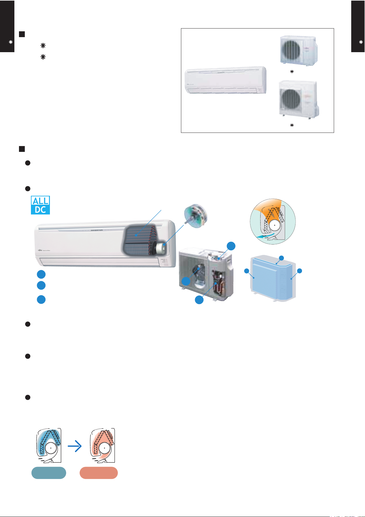
ALL DC
Large air flow and quiet
operation by new air
flow path
V-PAM technology makes a compressor more powerful.
V P
More compact compared with conventional model
Heat exchange capacities 20% up
compared to conventional models
Front view Back view
Air flow mode can be set in 4 steps and more detailed air flow setting is possible.
Easy maintenance
Easy maintenance and always clean. Troublesome maintenance has been made easy.
Since the front panel is easy to remove, maintenance is also easy.
Inner drying operation
This model is equipped with an inner drying function. After the power is turned off, the dry operation
starts inside the air conditioner. This prevents the growth of mold and bacterial inside the air conditioner.
AO R24LCC
AO R30LCT
High efficiency
layout
New 3-row heat
exchange system
V-P
V-PAM control
b
DC scroll compressor
c
a
DC fan motor
DC fan motor
b
a
c
1
2
3
During dew
condensation
Approx. 20 mins
Drying
Page 3
- (01 - 02) -
WALL MOUNTED TYPE
AS A24-30LC
WALL MOUNTED TYPE
AS A24-30LC
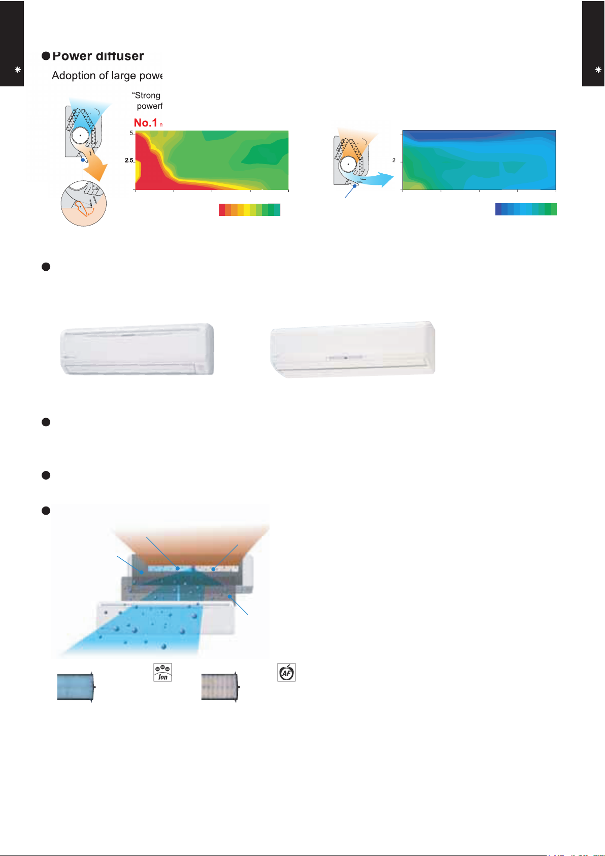
Power diffuser
Adoption of large power diffuser
Compact design
998mm width compact design
Low outdoor air temperature cooling correspondence
Corresponds to cooling operation at -10°Coutdoor air temperature
New model
Conventional model
H320 x W1,120 x D220
(unit:mm)
H320 x W998 x D228
2.52.5
5
0 3 6 9 12(m)
Outside air conditions: 2 oC 60%
( C)
Operation contents: Heating,
Set temperature (Max set temp)
30
o
o
C, Air flow Hi,
Air direction downward and front
“Strong vertical air flow” provides
powerful floor level heating.
Power diffuser
Power diffuser
(full open)
“Healthy horizontal air flow” does not blow
cool air directly at the occupants in the room.
5
2.5
0 3 6 9 12(m)
Corresponds to maximum 50m long piping (30TYPE)
Organic coating fin used
heat exchanger
Pre Filter
Antibacterial deodorizing
pre-filter with special
ceramic powder
Ion Deodorization Filter
Apple-catechin Filter
Applecatechin Filter
Long-life Ion
Deodorization Filter
2933 32 31 30
Outside air conditions: 35 oC 40%
( C)
Operation contents: Cooling,
Set temperature (Min set temp)
18
o
o
C, Air flow Hi,
Air direction downward and front
1815 16 17
Air conditioner filter features
2.5
10kWNo.1 attainedmaximum heating capacity
Adoption of large power diffuser
5
powerful floor level heating.
2.5
2.52.52.52.52.52.52.5
46
o
2.5
Page 4
- (01 - 03) -
WALL MOUNTED TYPE
AS A24-30LC
WALL MOUNTED TYPE
AS A24-30LC
FEATURES
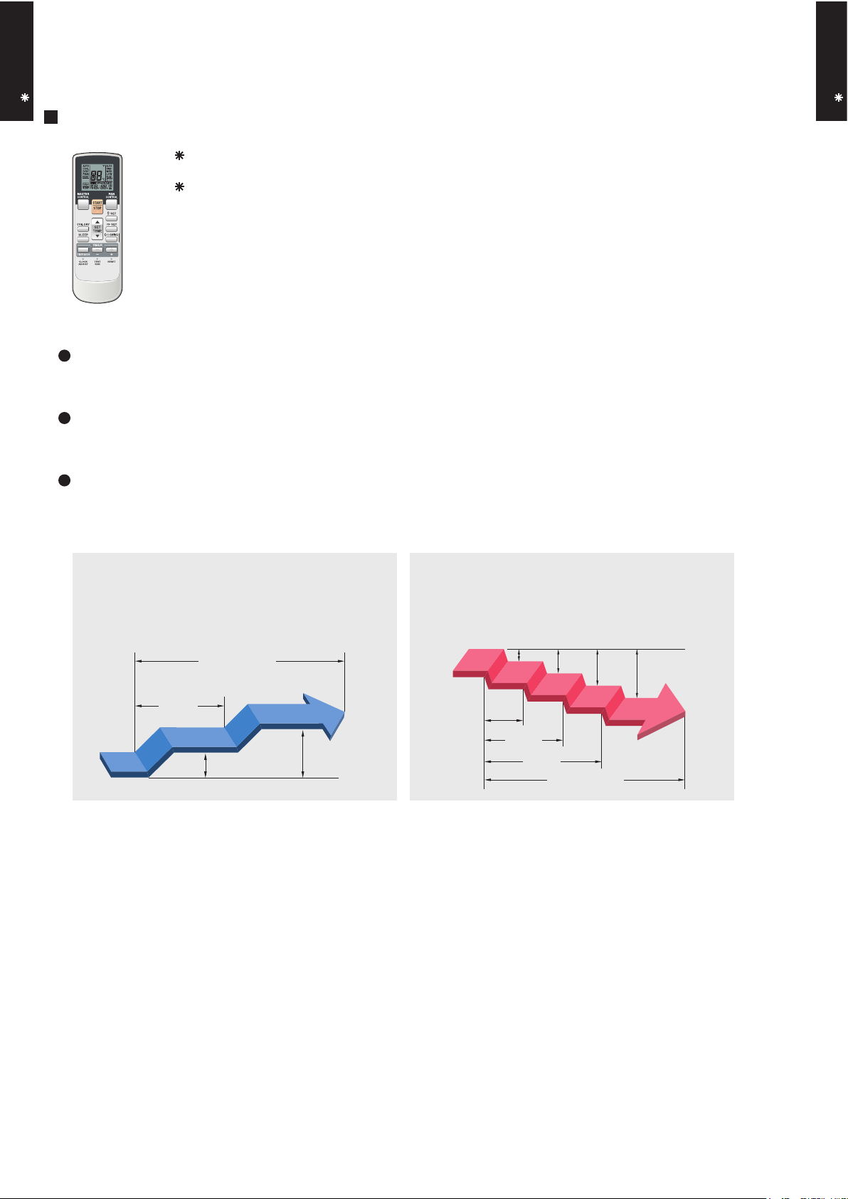
Four kinds of timer setup (ON / OFF / PROGRAM / SLEEP) are possible.
Four kinds of timers. Easy operation.
Select from four different timer programs (On/Off/Program/Sleep).
Built-in timers
The program timer operates the ON and OFF timer once within a 24 hour period.
Program timer
The sleep timer function automatically corrects the temperature thermostat setting according to the
time setting to prevent excessive cooling and heating while sleeping.
Sleep timer
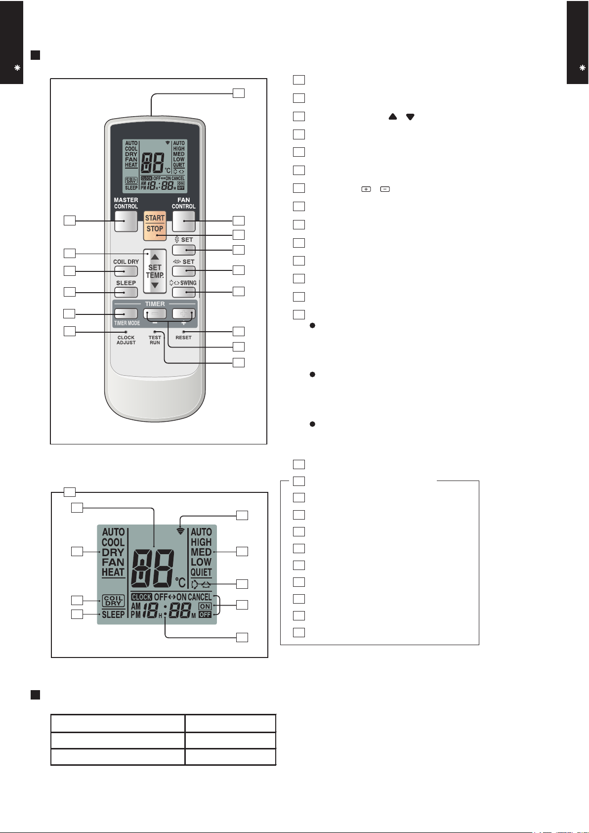
2-1. WIRELESS REMOTE CONTROLLER
2.
REMOTE CONTROLLER
Cooling operation/dry operation
60min.
1 °C
2 °C
When the sleep timer is set, the set temperature
automatically rises 1 °C every hour. The set
temperature can rise up to a maximum of 2 °C.
Heating operation
When the sleep timer is set, the set temperature
automatically drops 1 °C every 30 minutes. The
set temperature can drop to a maximum of 4 °C.
1 °C
30min.
60min.
90min.
2 °C
3 °C
4 °C
Timer setting
Timer setting
Page 5
- (01 - 04) -
WALL MOUNTED TYPE
AS A24-30LC
WALL MOUNTED TYPE
AS A24-30LC
Display panel
FUNCTIONS
SPECIFICATION
SIZE (H x W x D mm) 176 x 56 x 18
WEIGHT ( g ) 110
ACCESSORY Holder
TIMER SET ( / ) button
SET button (Horizontal)
TEST RUN button
This button is used when installing the
conditioner, and should not be used under normal conditions, as it will cause the
air conditioner’s thermostat function to operate incorrectly.
If this button is pressed during normal operation, the unit will switch to test operation mode, and the Indoor Unit’s OPERATION Indicator Lamp and TIMER Indicator
Lamp will begin to flash simultaneously.
To stop the test operation mode, press the
START/STOP button to stop the air conditioner.
CLOCK ADJUST button
Remote Control Unit Display
Transmit Indicator
Clock Display
Operating Mode Display
Timer Mode Display
Fan Speed Display
Temperature SET Display
SLEEP button
MASTER CONTROL button
/ )
SET TEMP. button (
COIL DRY button
Signal Transmitter
TIMER MODE button
FAN CONTROL button
START/STOP button
SET button (Vertical)
SWING button
RESET button
COIL DRY Display
SLEEP Display
SWING Display
4
5
6
7
8
9
18
20
21
22
23
24
25
19
17
2
3
10
12
11
15
16
14
1
13
2
4
9
3
1
15
5
17
18
19
21
24
23
22
25
10
13
11
12
14
8
7
6
20
16
Page 6
- (01 - 05) -
WALL MOUNTED TYPE
AS A24-30LC
WALL MOUNTED TYPE
AS A24-30LC
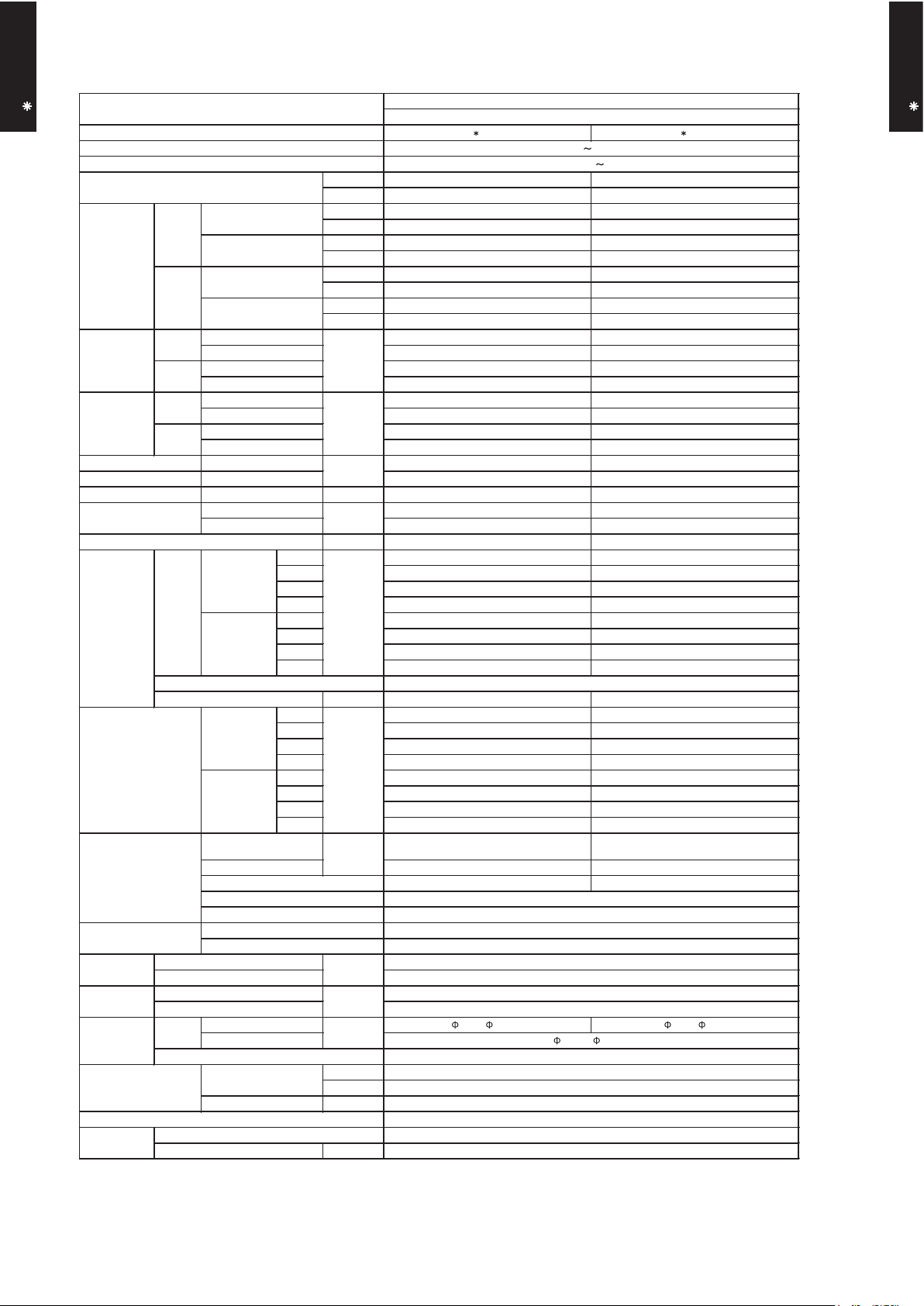
3. SPECIFICATIONS
AS A24LCC AS A30LCC
Cooling A B
Heating A B
kW 7.10 8.00
BTU/h 24,200 27,300
kW 0.9 - 8.0 2.9 - 9.0
BTU/h 3,100 - 27,300 9,900 - 30,700
kW 8.10 9.00
BTU/h 27,600 30,700
kW 0.9 - 10.6 2.2 - 11.0
BTU/h 3,100 - 36,200 7,500 - 37,600
2.21 2.66
0.11 - 2.62 0.58 - 3.60
2.24 2.64
0.11 - 3.68 0.50 - 4.30
9.7 11.7
12 17
9.8 11.6
17.5 19
3.21 3.01
3.62 3.41
kW 5.54 5.34
99 99
99 99
l/h (pints/h) 3.0 (5.3) 3.4 (6.0)
High 1100 1100
Med 900 900
Low 740 740
Quiet 620 620
High 1100 1100
Med 900 900
Low 740 740
Quiet 620 620
W 42 42
High 47 47
Med 41 41
Low 36 36
Quiet 32 32
High 45 45
Med 41 41
Low 36 36
Quiet 32 32
Dimensions (H × W × D)
Main : 378 × 832 × 26.6
Sub : 84 × 832 × 13.3
Main : 378 × 832 × 26.6
Sub1 : 84 × 832 × 13.3, Sub2 : 84 × 832 × 13.3
Main : 1.2, Sub : 1.4 Main : 1.2, Sub1 : 1.4, Sub2 : 1.4
Main : 2 × 18, Sub : 1 × 4 Main : 2 × 18, Sub : 1 × 4, Sub2 : 1 × 4
°C
%RH
°C
mm
Note :
Specifications are based on the following conditions.
Cooling : Indoor temperature of 27°CDB/19°CWB. and outdoor temperature of 35°CDB/24°CWB.
Heating : Indoor temperature of 20°CDB/15°CWB. and outdoor temperature of 7°CDB/6°CWB.
Pipe length : 7.5 m, Height difference : 0 m.(Outdoor unit - Indoor unit)
Heating
Size
Liquid
Gas
Method
Cooling
Net
Gross
Net
Gross
Model name
EER
COP
Moisture removal
Cooling
Heating
Sound pressure level
dB(A)
Type
mm
Rated
Min-Max
Rated
Min-Max
Rated
Min-Max
Power source
Available voltage range
Capacity
Cooling
Heating
European energy label
Input power
Cooling
kW
Heating
Rated
Min-Max
A
Heating
Rated
Max
Rated
Max
Fan
Airflow
rate
Current
Cooling
SENSIBLE CAPACITY
POWER FACTOR
Type × Q'ty
Motor output
kW/kW
Cooling
Heating
%
Cooling
Heating
Cooling
mm
Weight
Heat exchanger type
Enclosure
Fin pitch
Rows x Stages
Pipe type
Fin type
Material
Colour
Remote controller type
Drain pipe
Material
Cooling
Heating
m3/h
Operation range
kg(lb.)
Connection pipe
Size
mm
Dimensions
(H × W × D)
WALL MOUNTED
INVERTER HEAT PUMP
230V 50Hz
198 - 264V 50Hz
Cross flow fan × 1
Copper
Aluminium
Polystyrene
White
Flare
18 to 32
80 or less
320 × 998 × 228
319 × 1090 × 429
14 (30.8)
18 (39.6)
6.35 ( 1/4 in.) 9.52 ( 3/8 in.)
15.88 ( 5/8 in.)
30 or less
Wireless
PVC
Outer diameter : 28 / Inner diameter : 16
Page 7
- (01 - 06) -
WALL MOUNTED TYPE
AS A24-30LC
WALL MOUNTED TYPE
AS A24-30LC
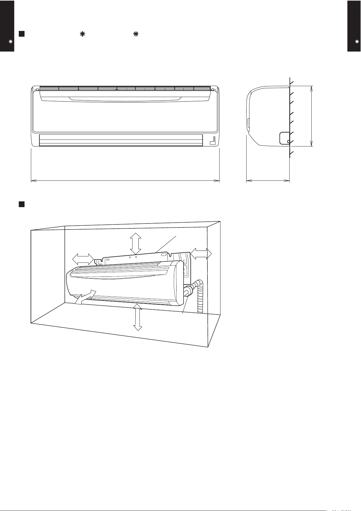
4. DIMENSIONS
MODEL : AS A24LC, AS A30LC
(Unit : mm)
998
228
320
MOUNTING POSITION
5 cm or over
Wall hook bracket
6 cm or over
5 cm or over
150 cm or over
(Wall cap)
230 cm or over
Page 8
- (01 - 07) -
WALL MOUNTED TYPE
AS A24-30LC
WALL MOUNTED TYPE
AS A24-30LC
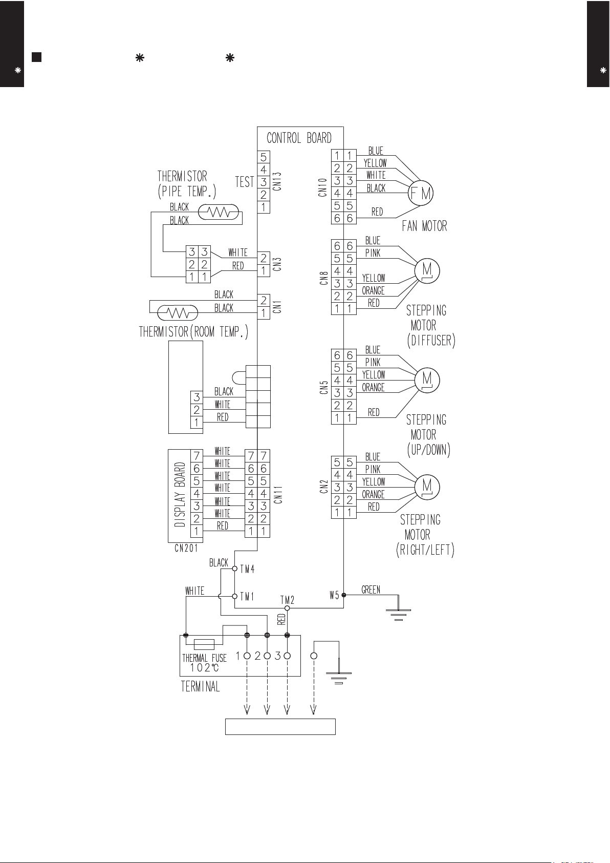
5. WIRING DIAGRAMS
MODEL : AS A24LC, AS A30LC
CN6
5
4
3
2
1
5
4
3
2
1
REMOTE CONTROL UNIT
(OPTION)
TO OUTDOOR UNIT
Page 9
- (01 - 08) -
WALL MOUNTED TYPE
AS A24-30LC
WALL MOUNTED TYPE
AS A24-30LC
6. CAPACITY TABLE
6-1. COOLING CAPACITY
MODEL : AS A24LC
MODEL : AS A30LC
AFR : Air flow rate (m3/min)
TC : Total capacity (kW)
SHC : Sensible Heat capacity (kW)
PI : Power Input (kW)
°CDB
°CWB
TC SHC PI TC SHC PI TC SHC PI TC SHC PI TC SHC PI TC SHC PI TC SHC PI
6.31 4.51 1.33 7.03 4.53 1.35 7.27 4.93 1.36 7.75 4.94 1.37 7.99 5.34 1.38 8.47 5.32 1.39 8.95 5.66 1.41
7.00 4.86 2.09 7.79 4.89 2.12 8.06 5.31 2.13 8.59 5.33 2.15 8.85 5.75 2.16 9.39 5.73 2.19 9.92 6.10 2.21
6.66 4.68 2.32 7.42 4.70 2.36 7.67 5.11 2.37 8.18 5.13 2.39 8.43 5.54 2.41 8.94 5.52 2.43 9.44 5.88 2.45
6.32 4.51 2.57 7.04 4.54 2.61 7.28 4.93 2.62 7.76 4.95 2.65 8.00 5.34 2.66 8.48 5.32 2.69 8.96 5.67 2.71
5.68 4.20 2.77 6.33 4.23 2.82 6.55 4.60 2.83 6.98 4.61 2.86 7.19 4.98 2.87 7.63 4.96 2.90 8.06 5.29 2.93
5.34 4.04 2.80 5.95 4.07 2.84 6.15 4.42 2.85 6.56 4.44 2.88 6.76 4.79 2.90 7.16 4.77 2.93 7.57 5.08 2.96
AFR
18.3
43
25
30
35
40
Indoor temperature
Outdoor temperature
12
15
°CDB
20
232518
21
16
18
272932
231921
°CDB
°CWB
TC SHC PI TC SHC PI TC SHC PI TC SHC PI TC SHC PI TC SHC PI TC SHC PI
6.26 5.61 1.75 6.98 5.64 1.78 7.22 6.13 1.79 7.69 6.15 1.80 7.93 6.65 1.81 8.41 6.62 1.83 8.88 7.05 1.85
6.00 5.21 1.94 6.68 5.24 1.97 6.91 5.70 1.98 7.36 5.71 2.00 7.59 6.17 2.01 8.05 6.15 2.03 8.50 6.55 2.05
5.61 4.67 2.13 6.25 4.70 2.17 6.46 5.11 2.18 6.89 5.13 2.20 7.10 5.54 2.21 7.53 5.51 2.23 7.95 5.87 2.25
5.06 4.08 2.15 5.64 4.10 2.18 5.83 4.46 2.19 6.22 4.47 2.21 6.41 4.83 2.22 6.79 4.81 2.25 7.18 5.13 2.27
4.73 3.72 2.16 5.27 3.74 2.20 5.45 4.07 2.21 5.81 4.08 2.23 5.99 4.41 2.24 6.35 4.39 2.27 6.71 4.67 2.29
AFR
18.3
43
25
30
35
40
Indoor temperature
Outdoor temperature
12
15
°CDB
20
232518
21
16
18
272932
231921
5.26 4.97 1.05 5.86 5.00 1.07 6.06 5.43 1.07 6.46 5.45 1.09 6.66 5.88 1.09 7.05 5.86 1.10 7.45 6.24 1.11
Page 10
- (01 - 09) -
WALL MOUNTED TYPE
AS A24-30LC
WALL MOUNTED TYPE
AS A24-30LC
6-2. HEATING CAPACITY
MODEL : AS A24LC
MODEL : AS A30LC
AFR : Air flow rate (m3/min)
TC : Total capacity (kW)
PI : Power Input (kW)
TC PI TC PI TC PI TC PI TC PI
5.93 2.69 5.78 2.74 5.64 2.80 5.50 2.85 5.36 2.91
7.04 2.94 6.87 3.00 6.70 3.06 6.53 3.12 6.37 3.18
7.92 3.09 7.73 3.15 7.54 3.22 7.36 3.28 7.17 3.34
9.15 3.30 8.94 3.37 8.72 3.43 8.50 3.50 8.28 3.57
10.41 3.52 10.16 3.59 9.91 3.67 9.67 3.74 9.42 3.81
11.13 3.42 10.87 3.49 10.60 3.56 10.34 3.63 10.07 3.70
11.53 3.42 11.25 3.49 10.98 3.56 10.71 3.64 10.43 3.71
11.16 2.97 10.90 3.04 10.63 3.10 10.37 3.16 10.10 3.22
AFR
°CDB
18.3
-16
-11
-7
Outdoor temperature
8510
15 10
6
0
-2
7
°CDB
°CWB
-15
3
24
-10
Indoor temperature
-5
161820
22
TC PI TC PI TC PI TC PI TC PI
7.74 4.07 7.56 4.16 7.38 4.24 7.19 4.33 7.01 4.41
8.34 4.06 8.14 4.15 7.94 4.23 7.74 4.32 7.54 4.40
9.61 4.08 9.38 4.17 9.15 4.25 8.93 4.34 8.70 4.42
10.54 4.04 10.29 4.13 10.04 4.21 9.79 4.30 9.54 4.38
11.53 4.09 11.26 4.18 10.98 4.26 10.71 4.35 10.43 4.43
11.55 3.39 11.28 3.46 11.00 3.53 10.73 3.60 10.45 3.67
11.90 3.38 11.62 3.45 11.33 3.52 11.05 3.59 10.77 3.66
11.48 2.95 11.20 3.01 10.93 3.07 10.66 3.13 10.38 3.20
AFR
°CDB
18.3
-16
-11
-7
Outdoor temperature
8510
15 10
6
0
-27°CDB
°CWB
-15
3
24
-10
Indoor temperature
-5
161820
22
Page 11
- (01 - 10) -
WALL MOUNTED TYPE
AS A24-30LC
WALL MOUNTED TYPE
AS A24-30LC
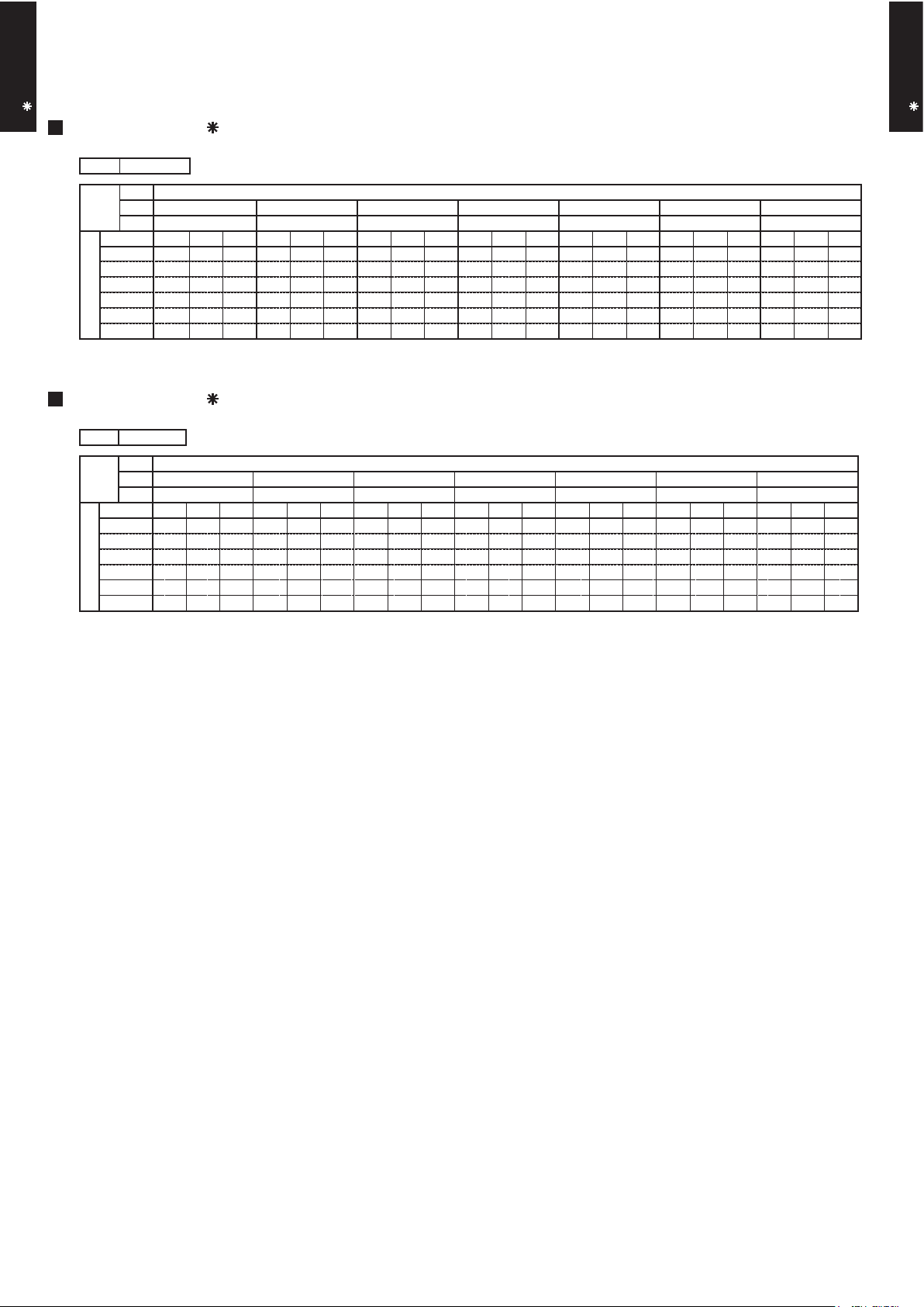
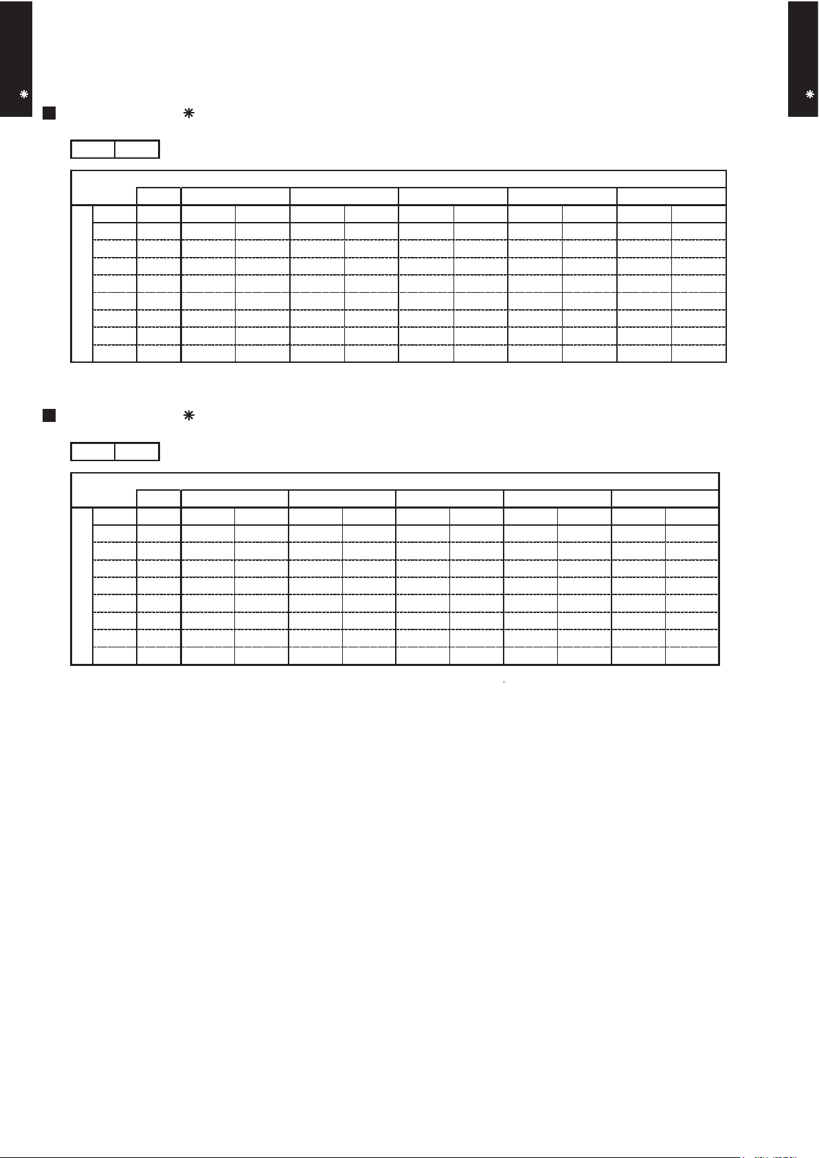
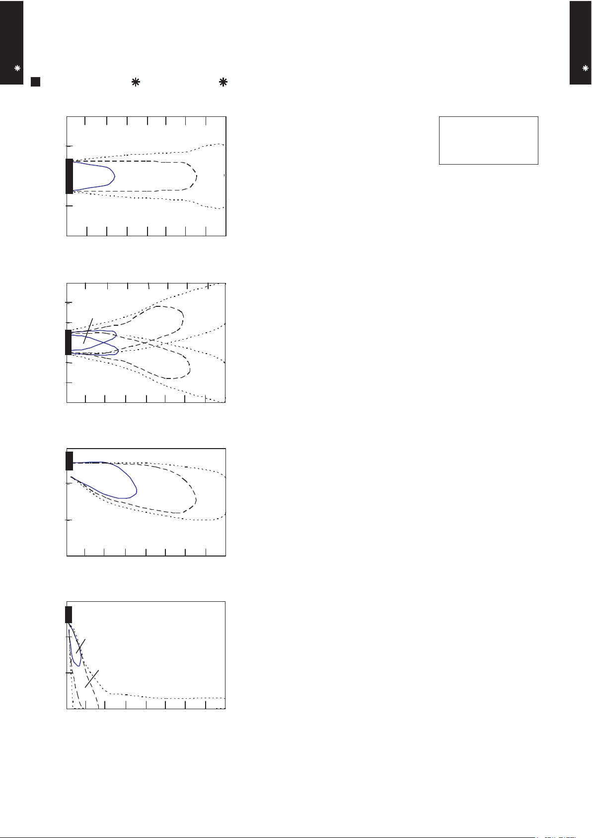
7. FAN PERFORMANCE
7-1. AIR VELOCITY DISTRIBUTION
MODEL : AS A24LC, AS A30LC
Note :
Fan speed : High
Voltage : 230V
Unit : m/s
Unit : m/s
Unit : m/s
Unit : m/s
TOP VIEW
FLOW CONTROL PANEL : Horiz.
LOUVER : Center
TOP VIEW
FLOW CONTROL PANEL : Horiz.
LOUVER : Right & Left
SIDE VIEW
FLOW CONTROL PANEL : Horiz.
LOUVER : Center
SIDE VIEW
FLOW CONTROL PANEL : Vert.
LOUVER : Center
(m)
(m)
(m)
(m)
(m)
(m)
(m)
(m)
Operation mode :FAN
2.0 1.0 0.5
1
765
43
2 8
1.0
0.5
0.5
2.0
1.0
1 765432 8
2.0
1.0
0.5
2.0
1.0
0.5
-3
-2
-1
0
1
2
3
-2
-1
0
1
2
0
1
2
3
1
765
43
2 8
0
1
2
3
1
765
43
2 8
Page 12

- (01 - 11) -
WALL MOUNTED TYPE
AS A24-30LC
WALL MOUNTED TYPE
AS A24-30LC
MODEL : AS A24LC
COOLING
7-2. AIR FLOW
m3/h
1100
l/s 306
CFM 647
m3/h
900
l/s 250
CFM 530
m3/h
740
l/s 206
CFM 435
m3/h
620
l/s 172
CFM 365
LOW
QUIET
1310
1120
940
830
Fan speed
Number of
rotations
(r.p.m)
Air flow
HIGH
MED
HEATING
m3/h
1100
l/s 306
CFM 647
m3/h
900
l/s 250
CFM 530
m3/h
740
l/s 206
CFM 435
m3/h
620
l/s 172
CFM 365
LOW
940
830
QUIET
HIGH
1310
1120
MED
Fan speed
Number of
rotations
(r.p.m)
Air flow
Page 13

- (01 - 12) -
WALL MOUNTED TYPE
AS A24-30LC
WALL MOUNTED TYPE
AS A24-30LC
MODEL : AS A30LC
COOLING
m3/h
1100
l/s 306
CFM 647
m3/h
900
l/s 250
CFM 530
m3/h
740
l/s 206
CFM 435
m3/h
620
l/s 172
CFM 365
LOW
QUIET
1330
1120
940
830
Fan speed
Number of
rotations
(r.p.m)
Air flow
HIGH
MED
HEATING
m3/h
1100
l/s 306
CFM 647
m3/h
900
l/s 250
CFM 530
m3/h
740
l/s 206
CFM 435
m3/h
620
l/s 172
CFM 365
LOW
940
830
QUIET
HIGH
1330
1120
MED
Fan speed
Number of
rotations
(r.p.m)
Air flow
Page 14

High
Quiet
- (01 - 13) -
WALL MOUNTED TYPE
AS A24-30LC
WALL MOUNTED TYPE
AS A24-30LC
8-1. NOISE LEVEL CURVE
8. OPERATION NOISE
MODEL : AS A24LC
Octave band sound pressure level, dB:(0dB=0.0002µbar)
Octave band center frequency,Hz
0
10
20
30
40
50
60
70
80
Octave band sound pressure level, dB:(0dB=0.0002µbar)
Octave band center frequency,Hz
0
10
20
30
40
50
60
70
80
Octave band sound pressure level, dB:(0dB=0.0002µbar)
0
10
20
30
40
50
60
70
80
63 125 250 500 1,000 2,000 4,000 8,000
Octave band center frequency,Hz
63 125 250 500 1,000 2,000 4,000 8,000
63 125 250 500 1,000 2,000 4,000 8,000
MODEL : AS A30LC
MODEL : AS A24LC
Octave band sound pressure level, dB:(0dB=0.0002µbar)
Octave band center frequency,Hz
0
10
20
30
40
50
60
70
80
63 125 250 500 1,000 2,000 4,000 8,000
MODEL : AS A30LC
COOLING
HEATING
High
Quiet
High
Quiet
NC-20
NC-40
NC-50
NC-60
NC-30
NC-15
NC-25
NC-35
NC-45
NC-55
NC-65
NC-20
NC-40
NC-50
NC-60
NC-30
NC-15
NC-25
NC-35
NC-45
NC-55
NC-65
High
Quiet
NC-20
NC-40
NC-50
NC-60
NC-30
NC-15
NC-25
NC-35
NC-45
NC-55
NC-65
NC-20
NC-40
NC-50
NC-60
NC-30
NC-15
NC-25
NC-35
NC-45
NC-55
NC-65
Page 15

- (01 - 14) -
WALL MOUNTED TYPE
AS A24-30LC
WALL MOUNTED TYPE
AS A24-30LC
8-2.
SOUND LEVEL CHECK POINT
Page 16

- (01 - 15) -
WALL MOUNTED TYPE
AS A24-30LC
WALL MOUNTED TYPE
AS A24-30LC
9. ELECTRIC CHARACTERISTICS
AS A24LC AS A30LC
Voltage V
Frequency Hz
Max Operating Current A 0.3 0.3
Circuit breaker A 0.4 0.4
Connection Cable
mm
2
1.5 - 2.5 1.5 - 2.5
Limited wiring length m 31 51
*1) Wiring Spec.
Selected Sample
(Selected based on Japan Electrotechnical Standard and Codes Committee E0005)
Model Name
*1)Wiring Spec.
Power Supply
230
50
Page 17

- (01 - 16) -
WALL MOUNTED TYPE
AS A24-30LC
WALL MOUNTED TYPE
AS A24-30LC
10. SAFETY DEVICES
AS A24LC AS A30LC
Circuit protection Current fuse (PCB)
Terminal protection Current fuse
Fan motor protection Thermal protection program
100
+15
-10
°C OFF
95
+5
-10
°C ON
Protection form
3.15A 250V
Model
3A 250V
Page 18

- (01 - 17) -
WALL MOUNTED TYPE
AS A24-30LC
WALL MOUNTED TYPE
AS A24-30LC
11. OPTIONAL PARTS
Exterior Summary
Parts name
Wired remote
controller
Apple-catechin
filter
Ion deodorisation
filter
Model No.
UTH-3TA16
UTR-FA13-1
UTR-FA13-2
Unit control is performed by
wired remote controller
Fine dust, invisible mold spores,
and harmful microorganisms
are absorbed onto the filter by
static electricity, and further
growth is inhibited and
deactivated by the polyphenol
ingredient extracted from
apples.
The filter deodorizes by
powerfully decomposing
absorbed odors using the
oxidizing and reducing effects
of ions generated by the ultra
fine-particle ceramic.
SUMOTUWETH FR
SA
AM
PM
3 6 9
12 15 18 21
Page 19

- (01 - 18) -
WALL MOUNTED TYPE
AS A24-30LC
WALL MOUNTED TYPE
AS A24-30LC
11-1. WIRED REMOTE CONTROLLER
Display panel
DIMENSION
SPECIFICATION
120
17
[ Unit : mm ]
SIZE (H x W x D mm) 120 x 120 x 17
WEIGHT ( g ) 160
CABLE LENGTH ( m )
POWER ( V )
10
12
15
11
10
9
8
2
1
3
5
14
4
12
13
6
7
17
16
18
19
20
21
120
Front View
FUNCTIONS
1
13
5
8
14
12
9
17
7
6
10
3
4
18
16
15
20
21
22
23
24
25
19
2
11
Start/Stop Button
Master Control Button
Fan Control Button
THERMO SENSOR Button
SET BACK Button
DELETE Button
SET Button
Horizontal airflow direction and swing Button
Operation Lamp
Operation Mode Display
Fan Speed Display
Operation Lock Display
Defrost Display
Horizontal Swing Display
Thermo Sensor Display
Energy Save Display
Set Temperature Button
Vertical airflow direction and swing Button
Set Time Button
DAY (DAY OFF) Button
Timer Mode (CLOCK ADJUST) Button
ENERGY SAVE Button
Timer and Clock Display
Temperature Display
Vertical Swing Display
DAY OFF
DELETE SET
ENERGY
SAVE
SET BACK
DAY
CLOCK ADJUST
SUMOTUWETH FR
SA
3 6 9
12 15 18 21
Display
SUMOTUWETH FR
SA
3 6 9
12 15 18 21
SUMOTUWETH FR
SA
AM
PM
3 6 9
12 15 18 21
23222425
1)
1) Button number and
cannot be operated.
5
6
Page 20

R410A
D1D_AO001E/01
2007.06.07
2.
SINGLE TYPE :
AO R24LCC
AO R30LCT
OUTDOOR UNIT
Page 21

OUTDOOR UNIT
AO R24-30LC
OUTDOOR UNIT
AO R24-30LC
- (02 - 01) -
1. SPECIFICATIONS
AO R24LCC AO R30LCT
A 9.8 11.7
2,340 3,600
2,470 3,800
W 65 100
52 53
53 55
Main : 546 × 866 × 36.4,
Sub : 504 × 589 × 18.2
798 × 900 × 36.4
Main : 1.4, Sub : 1.4 1.3
Main : 2 × 26, Sub : 1 × 24 2 × 38
Scroll × 1 Rotary × 1
W 1,200 1,700
g 1,600 2,100
578 × 790 × 315 830 × 900 × 330
648 × 910 × 380 970 × 1050 × 445
44 (97) 62 (137)
48 (105.8) 70 (154)
6.35 ( 1/4 in.) 9.52 ( 3/8 in.)
15.88 ( 5/8 in.) 15.88 ( 5/8 in.)
30 (chargeless : 15) 50 (chargeless : 20)
20 30
Note :
Specifications are based on the following conditions.
Cooling : Indoor temperature of 27°CDB/19°CWB. and outdoor temperature of 35°CDB/24°CWB.
Heating : Indoor temperature of 20°CDB/15°CWB. and outdoor temperature of 7°CDB/6°CWB.
Pipe length : 7.5 m, Height difference : 0 m. (Outdoor unit - Indoor unit)
Cooling
Heating
Colour
Net
Gross
Net
Type
Charge
Type
Material
Motor output
Cooling
Heating
Dimensions (H × W × D)
Type
Model name
Power source
Available voltage range
m
Connection pipe
Size
mm
Liquid
Gas
Method
Max. length
Max. height difference
Compressor
Refrigerant
Sound pressure level
Starting current
Cooling
Heating
Type × Q'ty
Refrigerant oil
Enclosure
Heat exchanger type
Fin pitch
Rows x Stages
Pipe type
Fin type
Type × Q'ty
Motor output
mm
Weight
kg(lb.)
Dimensions
(H × W × D)
Gross
°C
Operation range
Fan
Airflow
rate
m3/h
dB(A)
mm
INVERTER HEAT PUMP
230V 50Hz
198 - 264V 50Hz
Propeller fan × 1
Copper
Aluminium
R410A
Steel
PVE (FV50S)
Beige
Flare
-10 to 43
-15 to 24
Page 22

OUTDOOR UNIT
AO R24-30LC
OUTDOOR UNIT
AO R24-30LC
- (02 - 02) -
2. DIMENSIONS
MODEL : AO R24LC
(Unit : mm)
Air flow
Top view
600 mm or more
100 mm or more
300 mm or more
100 mm or more
300 mm or more
(Service space)
MOUNTING POSITION
Front view
Side view
Bottom view
If the space is larger that is stated, the condition will be the same as that are no obstacles.
Page 23

OUTDOOR UNIT
AO R24-30LC
OUTDOOR UNIT
AO R24-30LC
- (02 - 03) -
MODEL : AO R30LC
When there are obstacles at the
back or front sides.
When there are obstacles at the
back, side(s), and top.
When there are obstacles at the
back, side with the installation of
more than one unit.
600 mm
or more
250 mm
or more
250 mm
or more
300 mm
or more
600 mm or more
100 mm
or more
300 mm
or more
100 mm
or more
250 mm or more
(Service space)
MOUNTING POSITION
(Unit : mm)
603
Air flow
900
650
830
370
99
196
21
9
77
31 330
400
170
147
12
Top view
Front view
Side view
Bottom view
Page 24

OUTDOOR UNIT
AO R24-30LC
OUTDOOR UNIT
AO R24-30LC
- (02 - 04) -
MODEL : AO R24LC
3. REFRIGERANT CIRCUIT
2-Way
valve
Strainer
Strainer
Strainer
3-Way
valve
Muffler
4-Way valve
Expansion valve
Heat exchanger
( INDOOR )
Heat exchanger
( OUTDOOR )
Sub-accumulator
Compressor
Cooling
Heating
Refrigerant pipe diameter
Liquid : 1/4" (6.35 mm)
Gas : 5/8" (15.88 mm)
Page 25

OUTDOOR UNIT
AO R24-30LC
OUTDOOR UNIT
AO R24-30LC
- (02 - 05) -
MODEL : AO R30LC
3-Way
valve
(Small)
3-Way
valve
(Large)
Strainer
Strainer
Muffler
Pressure
switch
4-Way valve
Expansion valve
Heat exchanger
( INDOOR )
Heat exchanger
( OUTDOOR )
Sub-accumulator
Compressor
Refrigerant pipe diameter
Liquid : 3/8" (9.52 mm)
Gas : 5/8" (15.88 mm)
Cooling
Heating
Page 26

OUTDOOR UNIT
AO R24-30LC
OUTDOOR UNIT
AO R24-30LC
- (02 - 06) -
MODEL : AO R24LC
4. WIRING DIAGRAMS
TO INDOOR
UNIT
TO POWER
SUPPLY
Page 27

OUTDOOR UNIT
AO R24-30LC
OUTDOOR UNIT
AO R24-30LC
- (02 - 07) -
MODEL : AO R30LC
YELLOW
YELLOW
GREEN
BLUE
BLUE BLUE
YELLOW YELLOW
BLACK
BLACK BLACK
PURPLE
WHITE
WHITEWHITE
RED
RED RED
R
CM
C
S
BROWN
ORANGE
ORANGE
WHITE
WHITE
BLACK
BLACK BLACK
GREEN
RED
RED
RED
BROWN
BROWN
BROWN
BROWN
BROWN
BROWN
RED
RED
BLUE
BLUE
BLUE
ORANGE
YELLOW
YELLOW
WHITE
WHITE
BLACK
BLACK
BLACK
BLACK
BLACK
ORANGE
PURPLE
GRAY
GRAY
BLACK
BLACK
BLACK
BLACK
WHITE
WHITE
WHITE
WHITE
WHITE
WHITE
WHITE
BROWN
RED
BROWN
BROWN
RED
RED
ORANGE
ORANGE
CONNECTOR
MAIN PWB
ACTPM
CONNECTOR
POSISTOR
FILT ER PWB
FUSE 250V 25A
TERMINAL
FAN
MOTOR
FM
PMV
4WV
EXPANSION
VALVE
HIGH PRESSURE SW
THERMISTOR(COMPRESSOR TEMP.)
THERMISTOR(OUTDOOR TEMP.)
THERMISTOR(PIPE)
THERMISTOR(DISCHARGE PIPE)
4-WAY
VALVE
CHOKE COIL
COMPRESSOR
IPM PWB
CAPACITOR
PWB
CN3 0 3 C N 3 01
CN4 2 CN4 0 CN2 0 0 CN4 0 0
CN11
L0
N2
W8
W7
W13
W12
N1
L2
W29
CN110
TM6 0 0
TM6 0 1
CN8 0 1
W4
CN7 0 0
CN5 0 0
CN6 0
CN6 1
CN6 1
CN6 4
CN9 0
CN1
W1
W2
W18
W17
W3
W21
W9
W20
W19
CN1 0 0
W28
W25
W26
L1
P
W30 6
W30 2
W30 1
W17
W16
TM1 0 2
W30 3
W
V
U
W30 4
W30 5
TM1 0 1
W30 7
54768
10
9321 21
54768
10
9321 21
5
4 6321
5
4 6321
321
3 L N21
33221
1
6
7
5
4
3
2
1
6
7
5
4
3
2
1
6
5
4
3
2
1
3
2
1
3
2
1
212
1
212
1
212
1
212
1
212
1
6
5
4
221
1
21
54768
10
9321 21
54768
10
9321 21
4321
4321
4321
4321
TO INDOOR
UNIT
TO POWER
SUPPLY
Page 28

OUTDOOR UNIT
AO R24-30LC
OUTDOOR UNIT
AO R24-30LC
- (02 - 08) -
5. COEFFICIENT OF COMPENSATION FOR PIPE LENGTH
AND HEIGHT DIFFERENCE
MODEL : AO R24LC
Indoor unit
Height difference H
Connection pipe
H
Outdoor unit
Indoor unit
Connection pipe
H
Outdoor unit
Indoor unit is upper than outdoor unit.
1
Indoor unit is under than outdoor unit.
2
5 7.5 10 15 20 25 30
20 - - - 0.951 0.952 0.951 0.951
10 - - 0.980 0.966 0.968 0.967 0.966
7.5 - 0.988 0.984 0.970 0.972 0.971 0.970
5 0.995 0.992 0.988 0.974 0.976 0.975 0.974
0 1.003 1.000 0.996 0.982 0.983 0.983 0.982
-5 1.003 1.000 0.996 0.982 0.983 0.983 0.982
-7.5 - 1.000 0.996 0.982 0.983 0.983 0.982
-10 - - 0.996 0.982 0.983 0.983 0.982
-20 - - - 0.982 0.983 0.983 0.982
COOLING
*1
Indoor unit is
upper than outdoor
unit.
*2
Indoor unit is
under than outdoor
unit
Height
difference H
(m)
Pipe length (m)
5 7.5 10 15 20 25 30
20 - - - 0.975 0.954 0.932 0.908
10 - - 0.998 0.975 0.954 0.932 0.908
7.5 - 1.000 0.998 0.975 0.954 0.932 0.908
5 0.989 1.000 0.998 0.975 0.954 0.932 0.908
0 0.989 1.000 0.998 0.975 0.954 0.932 0.908
-5 0.984 0.995 0.993 0.970 0.950 0.927 0.903
-7.5 - 0.993 0.991 0.968 0.947 0.925 0.901
-10 - - 0.988 0.965 0.945 0.923 0.899
-20 - - - 0.956 0.935 0.914 0.890
HEATING
Pipe length (m)
Height
difference H
(m)
*1
Indoor unit is
upper than outdoor
unit.
*2
Indoor unit is
under than outdoor
unit
Page 29

OUTDOOR UNIT
AO R24-30LC
OUTDOOR UNIT
AO R24-30LC
- (02 - 09) -
MODEL : AO R30LC
Indoor unit
Height difference H
Connection pipe
H
Outdoor unit
Indoor unit
Connection pipe
H
Outdoor unit
Indoor unit is upper than outdoor unit.
1
Indoor unit is under than outdoor unit.
2
5 7.5 10 20 30 40 50
20 - - - 0.945 0.947 0.945 0.940
10 - - 0.984 0.961 0.963 0.960 0.956
7.5 - 0.988 0.988 0.965 0.967 0.964 0.959
5 0.990 0.992 0.992 0.968 0.971 0.968 0.963
0 0.998 1.000 1.000 0.976 0.979 0.976 0.971
-5 0.998 1.000 1.000 0.976 0.979 0.976 0.971
-7.5 - 1.000 1.000 0.976 0.979 0.976 0.971
-10 - - 1.000 0.976 0.979 0.976 0.971
-20 - - - 0.976 0.979 0.976 0.971
Pipe length (m)
COOLING
*1
Indoor unit is
upper than
outdoor unit.
*2
Indoor unit is
under than
outdoor unit
Height
difference H
(m)
5 7.5 10 20 30 40 50
20 - - - 0.872 0.816 0.756 0.686
10 - - 0.991 0.872 0.816 0.756 0.686
7.5 - 1.000 0.991 0.872 0.816 0.756 0.686
5 0.986 1.000 0.991 0.872 0.816 0.756 0.686
0 0.986 1.000 0.991 0.872 0.816 0.756 0.686
-5 0.981 0.995 0.986 0.868 0.812 0.752 0.683
-7.5 - 0.993 0.983 0.866 0.810 0.750 0.681
-10 - - 0.981 0.864 0.808 0.748 0.679
-20 - - - 0.855 0.799 0.740 0.672
Height
difference H
(m)
*1
Indoor unit is
upper than
outdoor unit.
*2
Indoor unit is
under than
outdoor unit
Pipe length (m)
HEATING
Page 30

OUTDOOR UNIT
AO R24-30LC
OUTDOOR UNIT
AO R24-30LC
- (02 - 10) -
6. ADDITIONAL CHARGE CALCULATION
MODEL : AO R24LC
REFRIGERANT CHARGE
MODEL : AO R30LC
REFRIGERANT CHARGE
Refrigerant type
Refrigerant amount g
Pipe length m 15 20 25 30
Additional charge g 0 (Chargeless) +100 +200 +300
R410A
20g/m
1600
Refrigerant type
Refrigerant amount g
Pipe length m 20 30 40 50
Additional charge g 0 (Chargeless) +400 +800 +1200
40g/m
R410A
2100
Page 31

OUTDOOR UNIT
AO R24-30LC
OUTDOOR UNIT
AO R24-30LC
- (02 - 11) -
MODEL : AO R24LC
7. AIR FLOW
COOLING
HEATING
MODEL : AO R30LC
COOLING
HEATING
m3/h
2340
l/s 650
CFM 1377
Air flow
Number of
rotations
(r.p.m)
1000
m3/h
2470
l/s 686
CFM 1454
1050
Air flow
Number of
rotations
(r.p.m)
m3/h
3600
l/s 1000
CFM 2119
Air flow
Number of
rotations
(r.p.m)
850
m3/h
3800
l/s 1056
CFM 2236
900
Air flow
Number of
rotations
(r.p.m)
Page 32

OUTDOOR UNIT
AO R24-30LC
OUTDOOR UNIT
AO R24-30LC
- (02 - 12) -
8-1. NOISE LEVEL CURVE
MODEL : AO R24LC
Octave band sound pressure level, dB:(0dB=0.0002µbar)
Octave band center frequency,Hz
0
10
20
30
40
50
60
70
80
63 125 250 500 1,000 2,000 4,000 8,000
Octave band sound pressure level, dB:(0dB=0.0002µbar)
Octave band center frequency,Hz
0
10
20
30
40
50
60
70
80
63 125 250 500 1,000 2,000 4,000 8,000
MODEL : AO R30LC
8. OPERATION NOISE
COOLING
Octave band sound pressure level, dB:(0dB=0.0002µbar)
Octave band center frequency,Hz
0
10
20
30
40
50
60
70
80
63 125 250 500 1,000 2,000 4,000 8,000
MODEL : AO R24LC
Octave band sound pressure level, dB:(0dB=0.0002µbar)
Octave band center frequency,Hz
0
10
20
30
40
50
60
70
80
63 125 250 500 1,000 2,000 4,000 8,000
MODEL : AO R30LC
HEATING
NC-20
NC-40
NC-50
NC-60
NC-30
NC-15
NC-25
NC-35
NC-45
NC-55
NC-65
NC-20
NC-40
NC-50
NC-60
NC-30
NC-15
NC-25
NC-35
NC-45
NC-55
NC-65
NC-20
NC-40
NC-50
NC-60
NC-30
NC-15
NC-25
NC-35
NC-45
NC-55
NC-65
NC-20
NC-40
NC-50
NC-60
NC-30
NC-15
NC-25
NC-35
NC-45
NC-55
NC-65
Page 33

OUTDOOR UNIT
AO R24-30LC
OUTDOOR UNIT
AO R24-30LC
- (02 - 13) -
8-2. SOUND LEVEL CHECK POINT
Page 34

OUTDOOR UNIT
AO R24-30LC
OUTDOOR UNIT
AO R24-30LC
- (02 - 14) -
9. ELECTRIC CHARACTERISTICS
AO R24LC AO R30LC
Voltage V
Frequency Hz
Max Operating Current A 17.5 18.5
A 9.8 11.7
Main Fuse (Circuit breaker)
Current
A 30 30
Power Cable
mm
2
3.5 - 4.5 3.5 - 4.5
*2)Limited wiring length m 20 19
*1) Wiring Spec.
Selected Sample
(Selected based on Japan Electrotechnical Standard and Codes Committee E0005)
*2) Limited Wiring length :
This is the wiring length in case voltage descent is less than 2%.
When the wiring length becomes long, please select the wiring of a more larger diameter.
Model Name
Starting Current
Power Supply
*1) Wiring Spec.
230
50
Page 35

OUTDOOR UNIT
AO R24-30LC
OUTDOOR UNIT
AO R24-30LC
- (02 - 15) -
10. SAFETY DEVICES
AO R24LC AO R30LC
20A 250V 20A 250V
5A 250V 5A 250V
15A 250V 15A 250V
3.15A 250V 3.15A 250V
Fan motor protection
Thermal protection program
OFF : 110
+15
-10
°C
ON : 105
+15
-10
°C
OFF : 130±20°C
ON : 100±20°C
High Pressure Protection
Pressure Switch -
OFF : 4.2±0.1MPa
ON : 3.2±0.15MPa
Thermal protection program
(COMPRESSOR TEMP.)
-
OFF : 110°C
ON : After 40 minutes
Thermal protection program
(DISCHARGE TEMP.)
OFF : 110°C
ON : After 7 minutes
OFF : 110°C
ON : After 7 minutes
Compressor protection
Protection form
Model
Circuit protection
Current fuse (NEAR THE
TERMINAL)
Current fuse
(MAIN PRINTED CIRCUIT BOARD)
 Loading...