

Page 1
R410A
INDOOR UNIT
1. WALL MOUNTED TYPE :
ASA18LEC
D2D_AS027E/01
2008.10.08
Page 2
WALL MOUNTED TYPE
1
.
A18LE C
AS
FEATURE1.
MODEL
ASA18 LEC
FEATURES
Energy saving Rank A
Europe energy saving Rank A achieved
ALL DC
Heat exchange capacities 45% up
compared to conventional models
DC fan motor
AOR18LEC
WALL MOUNTED TYPE
A18LE C
AS
a
b
c
Super quiet
fan motor
DC
P
I-PAM control
I-PAM technology makes a compressor more powerful.
rotary compressor
DC
Air fl ow mode can be set in 4 steps and more detailed air fl ow setting is possible.
Easy maintenance
Easy maintenance and always clean. Troublesome maintenance has been made easy.
Since the front panel is easy to remove, maintenance is also easy.
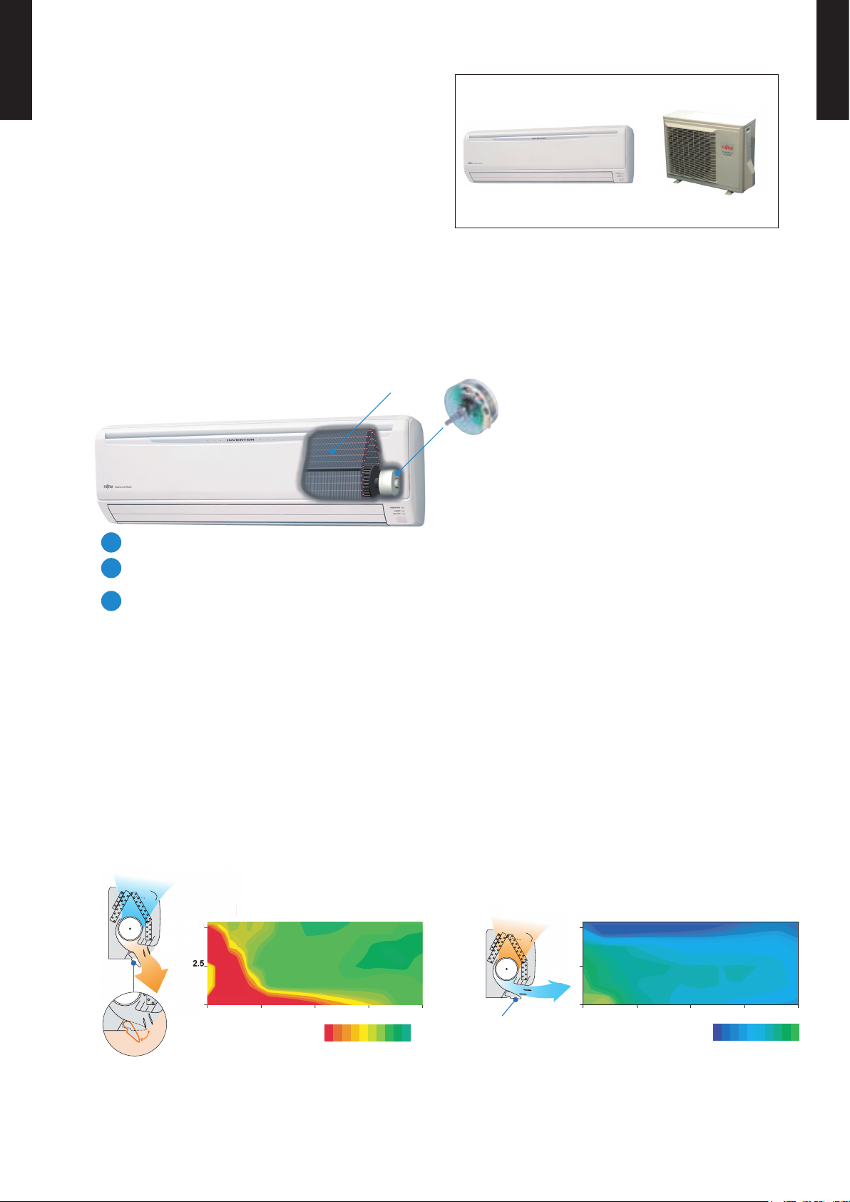
Power diffuser
Adoption of large power diffuser
“Strong vertical air fl ow” provides
powerful fl oor level heating.
No.
5
9kWNo.1 attainedmaximum heating capacity
“Healthy horizontal air fl ow” does not blow
cool air directly at the occupants in the room.
5
2.52.5
2.5
2
0 3 6 9 12(m)
Outside air conditions: 2 oC 60%
o
46
Power diffuser
(full open)
Operation contents: Heating,
Set temperature (Max set temp)
o
30
C, Air flow Hi,
Air direction downward and front
o
( C)
2933 32 31 30
- (01 - 01) -
Power diffuser
2.5
0 36912(m)
Outside air conditions: 35 oC 40%
Operation contents: Cooling,
Set temperature (Min set temp)
o
18
C, Air flow Hi,
Air direction downward and front
o
( C)
1815 16 17
Page 3
WALL MOUNTED TYPE
A18LE C
AS
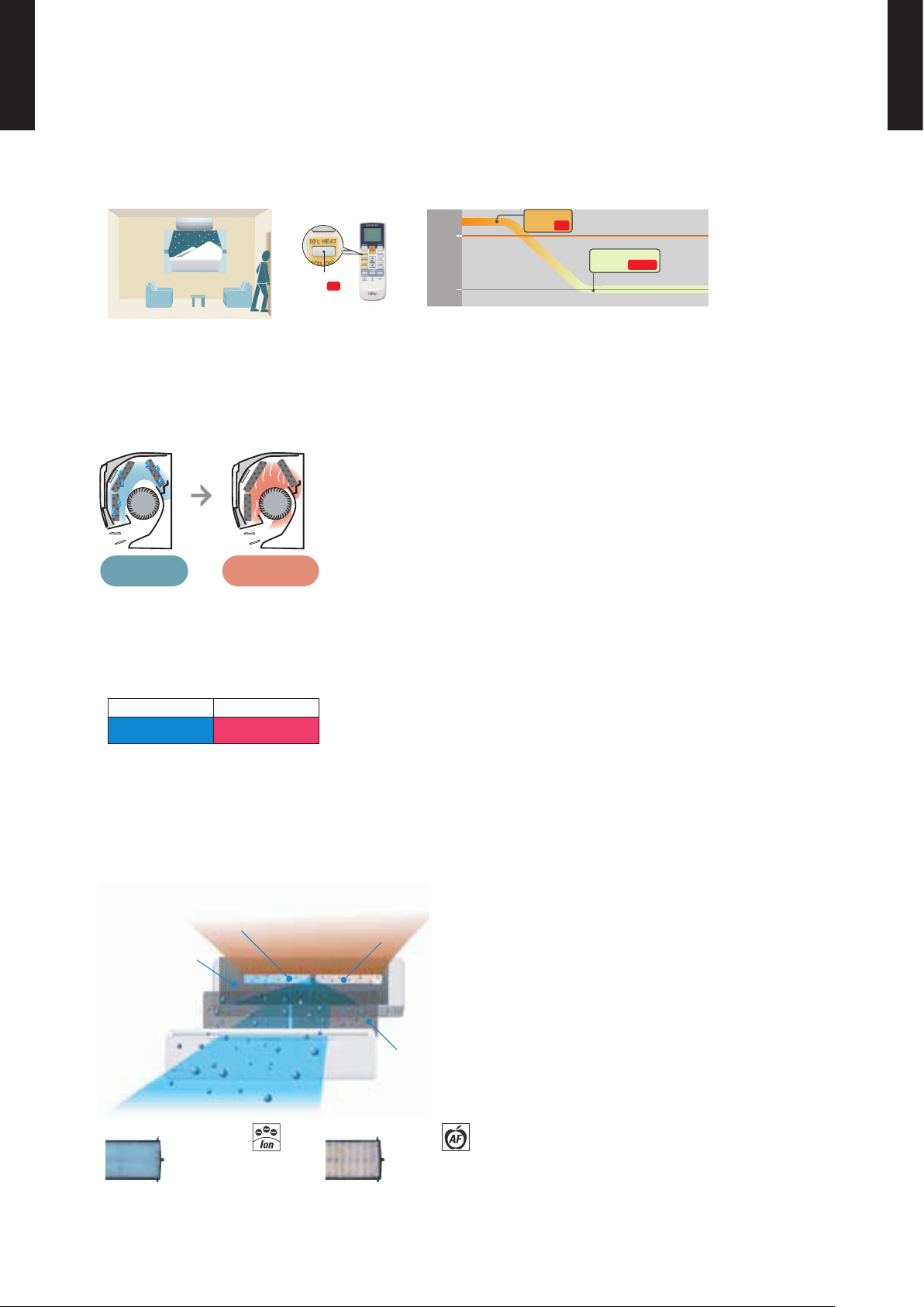
10°C HEAT Operation
The room temperature can be set to go no lower than 10°C,
thus ensuring that the room does not get too cold when not occupied
Caution)
When the room temperature is higher than 10°C, “10°C HE AT” operation does not start. Operation starts and maintains the room •
temperature at 10°C when the temperature drops below 10°C.
“10°C HEAT”
Button ON
Indoor unit
operation START
“10°C HEAT”
Button ON
Inner drying operation
20
°C
10
°C
This model is equipped with an inner drying function. After the power is turned off, the dry
operation starts inside the air conditioner. This prevents the growth of mold and bacteria inside the
air conditioner.
WALL MOUNTED TYPE
A18LE C
AS
During dew
condensation
Low outdoor air temperature correspondence
Approx. 90 mins
Drying
Corresponds to cooling operation at -10°C outdoor air temperature
Corresponds to heating operation at -15°C outdoor air temperature
Cooling Heating
-10 to 43
Corresponds to maximum 25m long piping
Air conditioner fi lter features
Organic coating fin used
heat exchanger
°C
-15 to 24
Ion Deodorization Filter
°C
Apple-catechin Filter
Long-life Ion
Deodorization Filter
Pre Filter
Antibacterial deodorizing
pre-filter with special
ceramic powder
Applecatechin Filter
- (01 - 02) -
Page 4
REMOTE CONTROLLER2.
WALL MOUNTED TYPE
A18LE C
AS
2-1. WIRED REMOTE CONTROLLER
FEATURES
Four kinds of timer setup (ON / OFF / PROGRAM / SLEEP)
are possible.
Four kinds of timers. Easy operation.
Built-in timers
Select from four different timer programs (On/Off/Program/Sleep).
Program timer
The program timer operates the ON and OFF timer once within a 24 hour period.
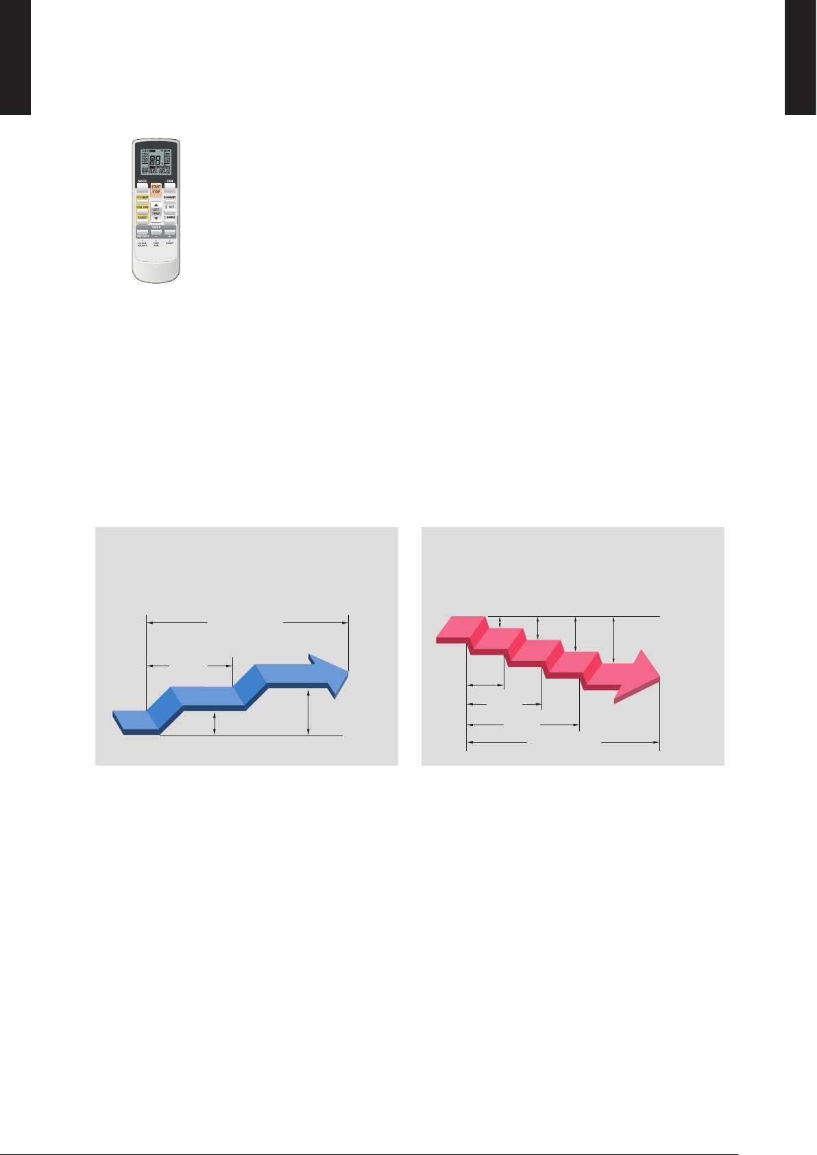
Sleep timer
WALL MOUNTED TYPE
A18LE C
AS
The sleep timer function automatically corrects the temperature thermostat setting according to
the time setting to prevent excessive cooling and heating while sleeping.
Cooling operation/dry operation
When the sleep timer is set, the set temperature
automatically rises 1 °C every hour. The set
temperature can rise up to a maximum of 2 °C.
Timer setting
60min.
1 °C
2 °C
Heating operation
When the sleep timer is set, the set temperature
automatically drops 1 °C every 30 minutes. The
set temperature can drop to a maximum of 4 °C.
1 °C
2 °C
3 °C
4 °C
30min.
60min.
90min.
Timer setting
- (01 - 03) -
Page 5
WALL MOUNTED TYPE
A18LE C
AS
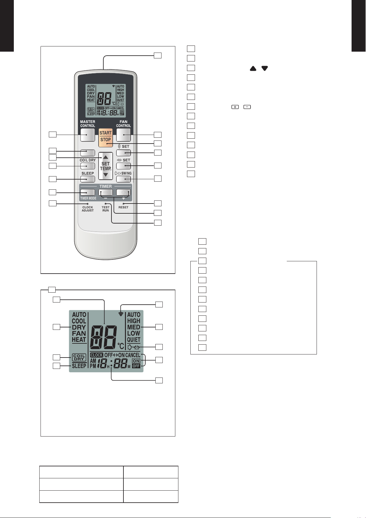
FUNCTIONS
2
16
3
4
1
6
15
17
23
20
24
25
10HEAT
10
11
12
13
14
5
8
9
7
18
22
26
21
1
SLEEP button
2
MASTER CONTROL button
3
SET TEMP. button ( / )
4
COIL DRY button
5
Signal Transmitter
6
TIMER MODE button
7
TIMER SET ( / ) button
8
FAN CONTROL button
9
START/STOP button
10
SET button (Vertical)
11
SET button (Horizontal)
12
SWING button
13
RESET button
14
TEST RUN button
This button is used when installing the conditioner, and should
not be used under normal conditions, as it will cause the air
conditioner’s thermostat function to operate incorrectly.
If this button is pressed during normal operation, the unit
will switch to test operation mode, and the Indoor Unit’s
OPERATION Indicator Lamp and TIMER Indicator Lamp will
begin to fl ash simultaneously.
To stop the test operation mode, press the START/STOP button
to stop the air conditioner.
15
CLOCK ADJUST button
16
10 °C HEAT button
17
Remote Control Unit Display
18
Tran smit In dica t or
19
Clock Display
20
Operating Mode Display
21
Timer Mode Display
22
Fan Speed Display
23
Temperature SET Display
24
COIL DRY Display
25
SLEEP Display
26
SWING Display
WALL MOUNTED TYPE
A18LE C
AS
19
To facilitate explanation, the accompanying
illustration has been drawn to show all possible
indicators; in actral operation, however, the display
will only shown those indicators appropriate to the
current operation.
SPECIFICATION
SIZE (H x W x D mm) 176 x 56 x 18
WEIGHT ( g ) 110
ACCESSORY Holder
- (01 - 04) -
Page 6
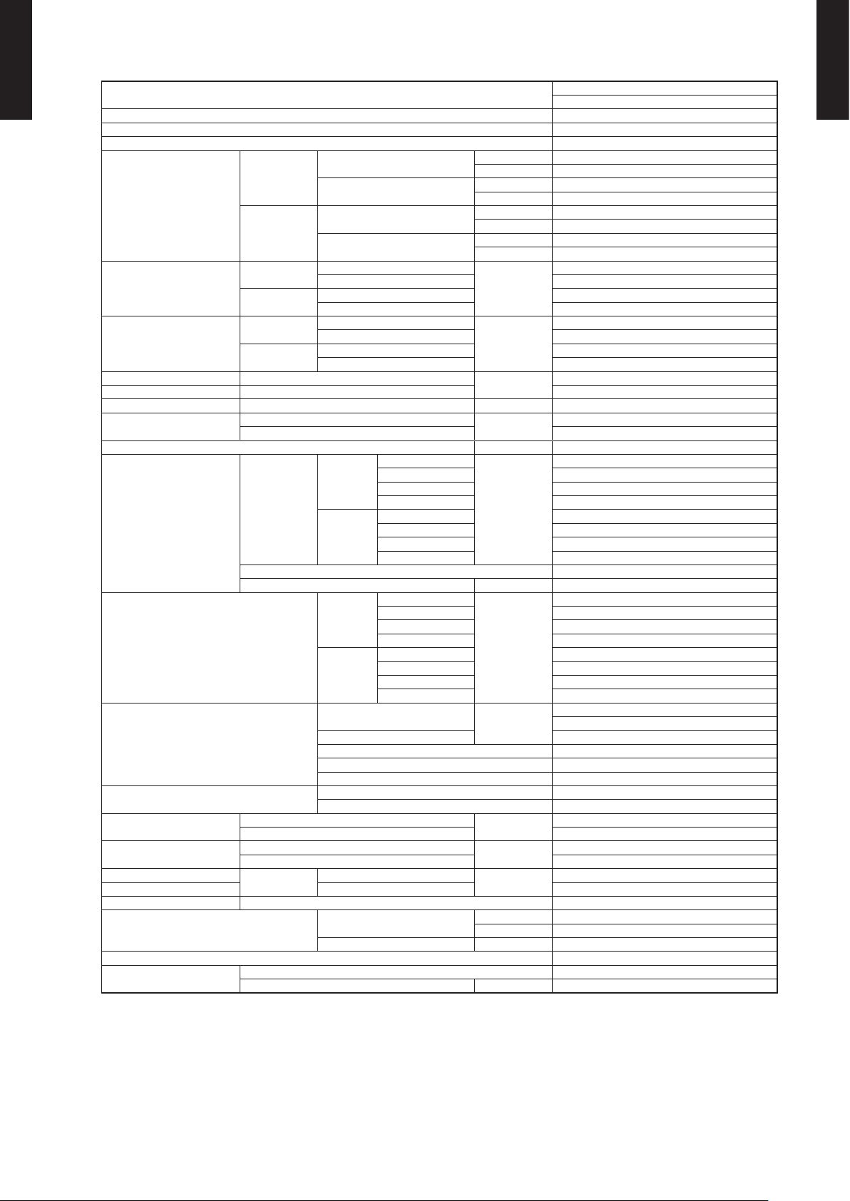
SPECIFICATIONS3.
WALL MOUNTED TYPE
A18LE C
AS
Type
Model name ASA18LEC
Power source 230V~ 50Hz
Available voltage range 198-264V~ 50Hz
Cooling
Capacity
Heating
Input power
Current
EER Cooling
COP Heating 3.68
SENSIBLE CAPACITY Cooling KW 4.5
POWER FACTOR
Moiature removal l/h(pints/h) 2.8
FAN
Noise level
Heat exchanger type
Enclosure
Dimensions(H × W × D)
Weight
Connection pipe
Operation range
Remote controller type Wireless
Drain pipe
Cooling
Heating
Cooling
Heating
Cooling
Heating 98
Airfl ow rate
Type× Q’ty Cross fl ow fan x 1
Motor output W 40
Net
Gross 319 x 1090 x 429
Net
Gross 18(39.6)
Size
Method Flare
Material PVC
Size mm Outer diameter:28/Outer diameter:16
Rated
Min-Max
Rated
Min-Max
Rated
Min-Max 0.09~2.07
Rated 1.71
Min-Max 0.09~2.87
Rated
Max 9.0
Rated 7.6
Max 12.5
High
Cooling
Heating
Cooling
Heating
Dimensions(H × W × D)
Fin pitch Main:1.2 Sub:1.4
Rows Stages Main:2 x 18 Sub:1 x 4
Pipe type Copper
Fin type Aluminium
Material Polystyrene
Colour White
Liquid
Gas Φ12.7(Φ1/2in)
Cooling
Heating °C 30 or less
Med 740
Low 620
Quiet 550
High 900
Med 740
Low 620
Quiet 550
High
Med 37
Low 33
Quiet 26
High 42
Med 37
Low 33
Quiet 25
KW 5.20
BTU/h 17,700
KW 0.9~6.0
BTU/h 3,100~20,500
KW 6.30
BTU/h 21,500
KW 0.9~9.1
BTU/h 3,100~31,000
KW
A
KW/KW
%
3
/h
m
dB(A)
mm
mm
kg(lb)
mm
°C 18~32
%RH 80 or less
WALL MOUNTED
INVERTER HEAT PUMP
1.52
6.8
3.42
97
900
43
Main:378 x 832 x 26.6
Sub:84 x 382 x 13.3
320 x 998 x 228
14(30.8)
Φ6.35(Φ1/4in)
WALL MOUNTED TYPE
A18LE C
AS
Note :
Specifi cations are ba sed on the fo llowing c onditio ns
Coolin g:Indoor te mperatur e of 27°C CDB /19°CCWB. and outdoo r temperat ure of 35°C CD B/24°CCW B.
Heatin g:Indoor te mperatur e of 20°C CDB /15°CCWB.an d outdoor te mperatu re of 7°C CDB /6°CCWB .
Pipe leng th:5m,He ight dif ference:0 m(Outdoo r unit-I ndoor unit)
The max imum curr ent is the ma ximum value w hen the ope rated wit hin the ope ration ran ge(tempe rature).
- (01 - 05) -
Page 7
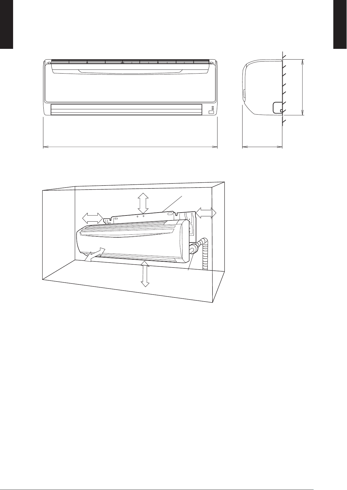
DIMENSIONS4.
WALL MOUNTED TYPE
A18LE C
AS
MODEL :ASA18 LEC
998
INSTALLATION PLACE
6 cm or over
5 cm or over
Wall hook bracket
228
(Unit : mm)
320
WALL MOUNTED TYPE
A18LE C
AS
150 cm or over
180 cm or over
5 cm or over
(Wall cap)
- (01 - 06) -
Page 8
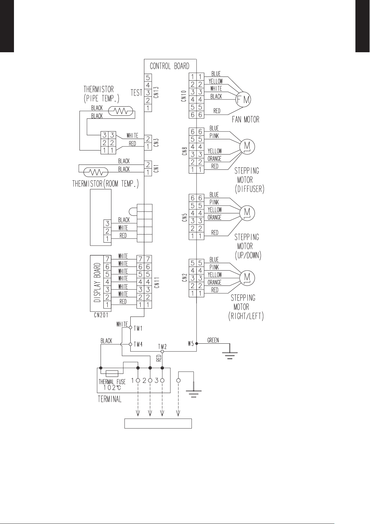
WIRING DIAGRAMS5.
WALL MOUNTED TYPE
A18LE C
AS
MODEL :ASA18 LEC
REMOTE CONTROL UNIT
(OPTION)
A18LE C
WALL MOUNTED TYPE
AS
5
5
4
4
3
3
2
1
CN6
2
1
TO OUTDOOR UNIT
- (01 - 07) -
Page 9
CAPACITY TABLE6.
WALL MOUNTED TYPE
A18LE C
AS
6-1. COOLING CAPACITY
MODEL :ASA18 LEC
AFR 15.0
°CDB 18 21 23 25 27 29 32
°CWB 12 15 16 18 19 21 23
°CDB TC SHC PI TC SHC PI TC SHC PI TC SHC PI TC SHC PI TC SHC PI TC SHC PI
20 4.10 3.78 0.76 4.57 3.80 0.77 4.73 4.14 0.78 5.04 4.16 0.79 5.19 4.49 0.79 5.51 4.47 0.80 5.82 4.76 0.80
25 4.54 4.43 1.19 5.06 4.45 1.21 5.23 4.85 1.22 5.58 4.87 1.23 5.75 5.25 1.23 6.10 5.24 1.25 6.44 5.58 1.26
30 4.33 4.12 1.33 4.82 4.15 1.35 4.99 4.51 1.36 5.32 4.53 1.37 5.48 4.89 1.38 5.81 4.88 1.39 6.14 5.19 1.40
35 4.11 3.79 1.47 4.58 3.82 1.49 4.73 4.15 1.50 5.04 4.17 1.51 5.20 4.50 1.52 5.51 4.49 1.54 5.82 4.78 1.55
40 3.69 3.16 1.58 4.11 3.18 1.61 4.25 3.46 1.62 4.53 3.47 1.63 4.67 3.75 1.64 4.96 3.74 1.66 5.24 3.98 1.67
Outdoor temperature
43 3.47 2.81 1.60 3.87 2.82 1.63 4.00 3.07 1.63 4.26 3.09 1.65 4.39 3.33 1.66 4.66 3.32 1.68 4.92 3.54 1.69
AFR : Air fl ow rate (m3/min)
TC : Total capac ity (kW)
SHC : Sens ible Heat c apacit y (kW)
PI : Power Inp ut (kW)
Indoor temperature
WALL MOUNTED TYPE
A18LE C
AS
- (01 - 08) -
Page 10

WALL MOUNTED TYPE
A18LE C
AS
6-2. HEATING CAPACITY
MODEL :
AFR 15.0
Outdoor temperature
AFR : Air fl ow rate (m3/min)
TC : Total capac ity (kW)
PI : Power Inpu t (kW)
ASA18 LEC
°CDB 16 18 20 22 24
°CDB °CWB TC PI TC PI TC PI TC PI TC PI
-15 -16 5.09 2.16 4.96 2.21 4.84 2.26 4.72 2.30 4.60 2.35
-10 -11 6.04 2.36 5.89 2.42 5.75 2.47 5.61 2.52 5.47 2.57
-5 -7 6.81 2.48 6.64 2.54 6.48 2.59 6.32 2.64 6.16 2.69
0 -2 7.86 2.65 7.67 2.72 7.48 2.77 7.29 2.83 7.11 2.89
5 3 8.94 2.83 8.72 2.90 8.51 2.96 8.30 3.01 8.09 3.08
7 6 9.56 2.75 9.33 2.82 9.10 2.87 8.87 2.92 8.65 2.99
10 8 9.91 2.75 9.66 2.82 9.43 2.87 9.19 2.92 8.97 2.99
15 10 9.59 2.38 9.36 2.44 9.13 2.49 8.90 2.54 8.68 2.59
Indoor temperature
WALL MOUNTED TYPE
A18LE C
AS
- (01 - 09) -
Page 11

FAN PERFORMANCE AND CAPACITY7.
WALL MOUNTED TYPE
A18LE C
AS
7-1. AIR VELOCITY DISTRIBUTION
MODEL :ASA18 LEC
2
1
0
1
2
012345678
3
2
1
2.0
1.0
0
2.0
1.0
1
Unit : m/s(m)
1.0
0.5
Unit : m/s(m)
0.5
0.5
TOP VIEW
FLOW CONT ROL PANEL : Ho riz.
LOUVER : C enter
(m)
TOP VIEW
FLOW CONT ROL PANEL : Ho riz.
LOUVER : R ight & Left
Note:
Fan speed : High
Operation mode : FAN
Voltage : 230V
WALL MOUNTED TYPE
A18LE C
AS
2
3
012345678
3
2
2.0
1
0
012345678
3
2
1.0
Unit : m/s(m)
0.5
Unit : m/s(m)
1.0
1
2.0
0.5
(m)
SIDE VIEW
FLOW CONT ROL PANEL : Ho riz.
LOUVER : C enter
(m)
SIDE VIEW
FLOW CONT ROL PANEL : Ver t.
LOUVER : C enter
0
012345678
- (01 - 10) -
(m)
Page 12

WALL MOUNTED TYPE
A18LE C
AS
7-2. AIR FLOW
MODEL :ASA18 LEC
COOLING / HEATING
Number of
Fan speed
rotations
(r.p.m)
Airfl ow
900 m3/h
WALL MOUNTED TYPE
A18LE C
AS
HIGH 1220
MED 1020
LOW 900
QUIET 710
250 l/s
530 CFM
740 m3/h
206 l/s
435 CFM
620 m3/h
172 l/s
365 CFM
550 m3/h
153 l/s
324
CFM
- (01 - 11) -
Page 13

OPERATION NOISE8.
WALL MOUNTED TYPE
A18LE C
AS
8-1. NOISE LEVEL CURVE
MODEL :ASA18 LEC
COOLING
80
70
60
50
40
30
20
Octave b and sound p ressur e level, dB:(0 dB=0. 0002μbar)
10
High
Quiet
NC-65
NC-60
NC-55
NC-50
NC-45
NC-40
NC-35
NC-30
NC-25
NC-20
NC-15
HEATING
80
70
60
50
40
30
20
Octave b and sound p ressur e level, dB:(0 dB=0. 0002μbar)
10
Quiet
High
NC-65
NC-60
NC-55
NC-50
NC-45
NC-40
NC-35
NC-30
NC-25
NC-20
NC-15
WALL MOUNTED TYPE
A18LE C
AS
0
63 125 250 500 1,000 2,000 4,000 8,000
Octave band center frequency,Hz
0
63 125 250 500 1,000 2,000 4,000 8,000
Octave band center frequency,Hz
- (01 - 12) -
Page 14

WALL MOUNTED TYPE
A18LE C
AS
8-2. SOUND LEVEL CHECK POINT
WALL MOUNTED TYPE
A18LE C
AS
- (01 - 13) -
Page 15

ELECTRIC CHARACTERISTICS9.
WALL MOUNTED TYPE
A18LE C
AS
Model Name ASA18 LEC
Voltage V 230 ~
Power Supply
Frequency Hz 50
Max Operating Current A 0.3
Circuit breaker A 0.4
*1)Wiring Spec.
Connection Cable mm
2
1.5 -2.5
Limited wiring length m 26
*1) Wiring Sp ec.
Seleted Sample
(Seleted b ased on Japa n Electro technic al Standa rd and Code s Commit tee E000 5)
WALL MOUNTED TYPE
A18LE C
AS
- (01 - 14) -
Page 16

SAFETY DEVICES10.
WALL MOUNTED TYPE
A18LE C
AS
Protection form
Model
ASA18 LEC
Circuit protection Current fuse (PCB) 3.15A 250V
Terminal protection Current (thermal) fuse 3A 250V
+15
Fan Motor protection Terminal protection program
OFF: 100
ON: 95
+5
-10
-10
°C
°C
WALL MOUNTED TYPE
A18LE C
AS
- (01 - 15) -
Page 17

OPTIONAL PARTS11.
WALL MOUNTED TYPE
A18LE C
AS
Exterior Parts name Model No. Summary
SUMOTUWETH FR
SA
AM
PM
369
12 15 18 21
Wired remote
controller
UTH-3TA16
Unit control is performed by
wired remote controller
Fine dust, invisible mold
spores, and harmful
microorganisms are absorbed
Apple-catechin
fi lter
UTR-FA13-1
onto the fi lter by
electricity
static
, and further growth
is inhibited and deactivated
by the polyphenol ingredient
extracted from apples.
The fi lter deodorizes by
Ion
deodorisation
fi lter
UTR-FA13-2
powerfully decomposing
absorbed odors using the
oxidizing and reducing effects
of ions generated by the ultra
fi ne-particle ceramic.
WALL MOUNTED TYPE
A18LE C
AS
- (01 - 16) -
Page 18

WALL MOUNTED TYPE
A18LE C
AS
11-1. WIRED REMOTE CONTROLLER
FUNCTIONS
1
Start/Stop Button
2
Set Temperature Button
3
Display
2
7
8
9
10
11
12
Display panel
16
SUMOTUWETH FR
369
SUMOTUWETH FR
369
CLOCK ADJUST
SET BACK
DELETE SET
12 15 18 21
12 15 18 21
DAY
DAY OFF
SA
SA
15
1
3
ENERGY
SAVE
19
20
18
23222425
4
5
6
13
14
17
21
Master Control Button
4
Fan Control Button
5
THERMO SENSOR Button
6
ENERGY SAVE Button
7
Timer Mode (CLOCK ADJUST) Button
8
DAY (DAY OFF) Button
9
SET BACK Button
10
Set Time Button
11
DELETE Button
12
SET Button
13
Horizontal airfl ow direction and swing Button
14
Vertical airfl ow direction and swing Button
15
Operation Lamp
16
Timer and Clock Display
17
Operation Mode Display
18
Fan Speed Display
19
Operation Lock Display
20
Temperature Display
21
Defrost Display
22
Vertical Swing Display
23
Horizontal Swing Display
24
Thermo Sensor Display
25
Energy Save Display
A18LE C
WALL MOUNTED TYPE
AS
1)
.
DIMENSION
[ Unit : mm ]
120
SUMOTUWETH FR
AM
PM
369
12 15 18 21
120
SA
Front View
SPECIFICATION
SIZE (H x W x D mm) 120 x 120 x 17
WEIGHT ( g ) 160
CABLE LENGTH ( m ) 10
*1) Button number 5 and 6 cannot be operated.
17
POWER ( V ) 12
- (01 - 17) -
Page 19

R410A
OUTDOOR UNIT
2. SINGLE TYPE :
AOR18LEC
D2D_AO029E/01
2008.10.08
Page 20

R18LE
OUTDOOR UNIT
AO
SPECIFICATIONS1.
Type INVERTER COOLING & HEATING
Model name AOR18LEC
Power source 230V~ 50Hz
Available voltage range 198-264V~ 50Hz
Starting current A 7.6
Cooling
Heating 2,070
m
3
/h
Fan
Airfl ow
rate
Type × Q'ty Propeller fan × 1
Motor output W 40
Sound pressure level
Cooling
Heating 52
dB(A)
Dimensions
Heat exchanger type
(H × W × D)
Fin pitch 1.3
mm
Rows x Stages 2 × 28
Pipe type Copper
Fin type Aluminium
Compressor
Refrigerant
Type × Q'ty Rotary × 1
Motor output W 900
Type R410 A
Charge g 1,200
Refrigerant oil Type FREOLα68SZ
Enclosure
Dimensions
( H × W × D)
Weight
Net
Gross 712 × 935 × 400
Net
Gross 45 (99)
Size
Connection
pipe
Method Flare
Max. length
Max. height difference 20
Operation range
Material Steel
Colour Beige
mm
kg(lb.)
Liquid
Gas Ø12.7 (Ø1/2 in.)
mm
m
Cooling
Heating -15 to 24
°C
Ø6.35 (Ø 1/4 in.)
25(chargeless:15)
2,070
50
588 × 881 × 36.4
620 × 790 × 298
40(88)
-10 to 43
R18LE
OUTDOOR UNIT
AO
Note :
Specifi cations are ba sed on the fo llowing c onditio ns.
Coolin g : Indoor te mperatur e of 27 °CDB / 19 °CW B.and outd oor tempe rature of 3 5 °CDB/24 °C WB.
Heatin g : Indoor tem peratur e of 20 °CDB / 15 °CW B.and outd oor tempe rature of 7 °C DB/6 °CW B.
Pipe leng th : 5 m, Heigh t differ ence : 0 m.(Outd oor unit - In door unit)
The max imum curr ent is the ma ximum value w hen the ope rated wit hin the ope ration ran ge(tempe rature).
- (02 - 01) -
Page 21

DIMENSIONS2.
MODEL :AOR18LE
(Unit : mm)
R18LE
OUTDOOR UNIT
AO
R18LE
OUTDOOR UNIT
AO
INSTALLATION PLACE
600 mm or more
100 mm or more
300 mm or more
(Service space)
300 mm or more
100 mm or more
If the space is larger that is stated, the condition will be the same as that are no obstacles.
- (02 - 02) -
Page 22

REFRIGERANT CIRCUIT3.
MODEL :AOR18LE
R18LE
OUTDOOR UNIT
AO
R18LE
OUTDOOR UNIT
AO
Refrigerant pipe diameter
Liquid : 1/4" (6.35 mm)
Gas : 1/2" (12.7 mm)
- (02 - 03) -
Page 23

WIRING DIAGRAMS4.
MODEL :AOR18LE
R18LE
OUTDOOR UNIT
AO
R18LE
OUTDOOR UNIT
AO
- (02 - 04) -
Page 24

CAPACITY COMPENSATION RATE FOR PIPE LENGTH5.
AND HEIGHT DIFERENCE
MODEL :AOR18LE
R18LE
OUTDOOR UNIT
AO
Height difference H
(m)
Height difference H
(m)
COOLING
1
Indoor unit is upper
than outdoor unit.
2
Indoor unit is under
than outdoor unit
COOLING
1
Indoor unit is upper
than outdoor unit.
2
Indoor unit is under
than outdoor unit
Pipe length (m)
510152025
20 - - - 0.869 0.867
10 - 0.911 0.885 0.883
5 0.992 0.981 0.919 0.893 0.891
0 1.000 0.989 0.927 0.901 0.899
-5 1.000 0.989 0.927 0.901 0.899
-10 - 0.989 0.927 0.901 0.899
-20 - - - 0.901 0.899
Pipe length (m)
510152025
20 - - - 0.901 0.879
10 - 0.989 0.927 0.901 0.879
5 1.000 0.989 0.927 0.901 0.879
0 1.000 0.989 0.927 0.901 0.879
-5 0.995 0.984 0.922 0.896 0.874
-10 - 0.979 0.917 0.892 0.869
-20 - - - 0.876 0.853
R18LE
OUTDOOR UNIT
AO
Height difference H
Indoor unit
Outdoor unit
Connection pipe
1 Indoor unit is upper than outdoor unit.
Outdoor unit
Indoor unit
Connection pipe
2 Indoor unit is under than outdoor unit.
- (02 - 05) -
Page 25

R18LE
OUTDOOR UNIT
AO
ADDITIONAL CHARGE CALCULATION6.
MODEL :AOR18LE
Refrigerant type R410A
Refrigerant amount g 1200
REFRIGERANT CHARGE
Pipe length m ~15 20 25
Additional charge g 0 (Charge less) +100 +200
20g/m
R18LE
OUTDOOR UNIT
AO
- (02 - 06) -
Page 26

AIR FLOW7.
MODEL :AOR18LE
COOLING & HEATING
R18LE
OUTDOOR UNIT
AO
Number of rotations
(r.p.m)
870
Airfl ow
2070 m
575 l/s
1218 CFM
3
/h
R18LE
OUTDOOR UNIT
AO
- (02 - 07) -
Page 27

OPERATION NOISE8.
8-1. NOISE LEVEL CURVE
MODEL :AOR18LE
R18LE
OUTDOOR UNIT
AO
COOLING
80
70
60
50
40
30
20
Octave b and sound p ressur e level, dB:(0 dB=0. 0002μbar)
10
0
63 125 250 500 1,000 2,000 4,000 8,000
Octave band center frequency,Hz
NC-65
NC-60
NC-55
NC-50
NC-45
NC-40
NC-35
NC-30
NC-25
NC-20
NC-15
HEATING
80
70
60
50
40
30
20
Octave b and sound p ressur e level, dB:(0 dB=0. 0002μbar)
10
0
63 125 250 500 1,000 2,000 4,000 8,000
Octave band center frequency,Hz
NC-65
NC-60
NC-55
NC-50
NC-45
NC-40
NC-35
NC-30
NC-25
NC-20
NC-15
R18LE
OUTDOOR UNIT
AO
- (02 - 08) -
Page 28

8-2. SOUND LEVEL CHECK POINT
R18LE
OUTDOOR UNIT
AO
R18LE
OUTDOOR UNIT
AO
- (02 - 09) -
Page 29

R18LE
OUTDOOR UNIT
AO
ELECTRIC CHARACTERISTICS9.
Model Name AOR18LEC
Power Supply
Max Operating Current A 12.5
Starting Current A 7.6
*)Wiring Spec
*)Wirin g Spec
Seleted Sample
(Seleted b ased on Japa n Electro technic al Standa rd and Code s Commit tee E000 5)
*2)Limited Wiring length
This is th e wiring le ngth in cas e voltage d escent is l ess then 2%
When the w iring len gth beco mes long ,p lease sel ect the wir ing of a more l arger diam eter.
Voltage V 230 ~
Frequency Hz 50
Main Fuse
(Circuit breaker)Current
Power Cable mm
A20
2
3.5-4.0
*2)Limited Wiring length m 20
R18LE
OUTDOOR UNIT
AO
- (02 - 10) -
Page 30

SAFETY DEVICES10.
R18LE
OUTDOOR UNIT
AO
Protection form
Current fuse
Circuit protection
( I N T H E I N V E R T E R C A S E )
Current fuse
(MAIN PRINTED CIRCUIT BOARD)
Fan Motor protection Terminal protection program
Terminal protection program
Compressor protection
COMPRESSOR TEMP.
Terminal protection program
COMPRESSOR TEMP.
Model
AOR18LEC
20A 250V
5A 250V
15A 250V
3.15A 250V
+10
OFF:100
ON:95
+10
°C
-10
°C
-10
-
OFF:110°C
ON:After 7 minutes
R18LE
OUTDOOR UNIT
AO
- (02 - 11) -
 Loading...