

Page 1
SPLIT TYPE
ROOM AIR CONDITIONER
WALL MOUNTED
Models
Indoor unit Outdoor unit
ASHA07LCC
ASHA09LCC
AOHR07LCC
AOHR09LCC
type
CONTENTS
SPECIFICATIONS
DIMENSIONS
REFRIGERANT SYSTEM DIAGRAM
CIRCUIT DIAGRAM
ERROR CONTENTS
DISASSEMBLY ILLUSTRATION
PARTS LIST
. . . . . . . . . . . . . . . . . . . . . .
. . . . . . . . . . . . . . . . . . . . . . . . . .
. . . . . . . . . . . . . . . . . . . .
. . . . . . . . . . . . . . . . . . .
. . . . . . . . .
. . . . . . . . . . . . . . . . . . . . . . . . . .
. . . . . . . . . . .
. . . . .
. . . . . .
. . .
1
2
3
4
5INDOOR PCB CIRCUIT DIAGRAM
6OUTDOOR PCB CIRCUIT DIAGRAM
8
9
14
16STANDARD ACCESSORIES
Page 2
SPECIFICATIONS
TYPE
INDOOR UNIT
OUTDOOR UNIT
COOLING CAPACITY
HEATING CAPACITY
ELECTRICAL DATA
POWER SOURCE
FREQUENCY
RUNNING CURRENT
INPUT WATTS
E.E.R.
COP
MOISTURE REMOVAL
AIR CIRCULATION
-High
COOLING
HEATING
COOLING
HEATING
COOLING
HEATING
COOLING
HEATING
COOL & HEAT INVERTER
ASHA07LCC
AOHR07LCC
2.10 kW
3.00 kW
230 V
50 Hz
2.5 A
3.2 A
0.47 kW
0.66 kW
4.47 kW/kW
4.55 kW/kW
1.0 L/hr
595 m3/hr
645 m3/hr
ASHA09LCC
AOHR09LCC
2.60 kW
3.60 kW
0.655 kW
0.845 kW
3.97 kW/kW
4.26 kW/kW
1.3 L/hr
595 m3/hr
645 m3/hr
230 V
50 Hz
3.2 A
4.0 A
DIMENSIONS
INDOOR UNIT
OUTDOOR UNIT
H x W x D
H x W x D
WEIGHT
INDOOR UNIT
OUTDOOR UNIT
GROSS / NET
GROSS / NET
NOISE LEVEL
High
INDOOR UNIT
OUTDOOR UNIT
Med
Low
Quiet
REFRIGERANT (R410A)
Pipe Length
FULL CHARGE AMOUNT
ADDITIONAL REFRIGERANT
MAXIMUM PIPING HEIGHT
15 m
20 m
275 x 790 x 215 mm
540 x 660 x 290 mm
12 / 9 kg
35 / 32 kg
Cool 41 dB / Heat 41 dB
Cool 36 dB / Heat 36 dB
Cool 30 dB / Heat 30 dB
Cool 21 dB / Heat 21 dB
Cool 47 dB / Heat 48 dB
900 g
1,000 g
20 g / m
15m
COMPRESSOR
TYPE
DISCRIMINATION
REFRIGERANT
FAN MOTOR
POWER SOURCE
HIGH-SPEED
INDOOR UNIT
OUTDOOR UNIT
MED-SPEED
LOW-SPEED
QUIET
R410A
Hermetic type, 4 pole, 3 phase,
DC inverter motor, Rotary
DA89X1C - 20FZ
900 g
230 V
Cool 1,300 / Heat 1,390 r.p.m.
Cool 1,120 / Heat 1,200 r.p.m.
Cool 950 / Heat 1,000 r.p.m.
Cool 700 / Heat 760 r.p.m.
800 r.p.m.
2006.04.24 1
Page 3
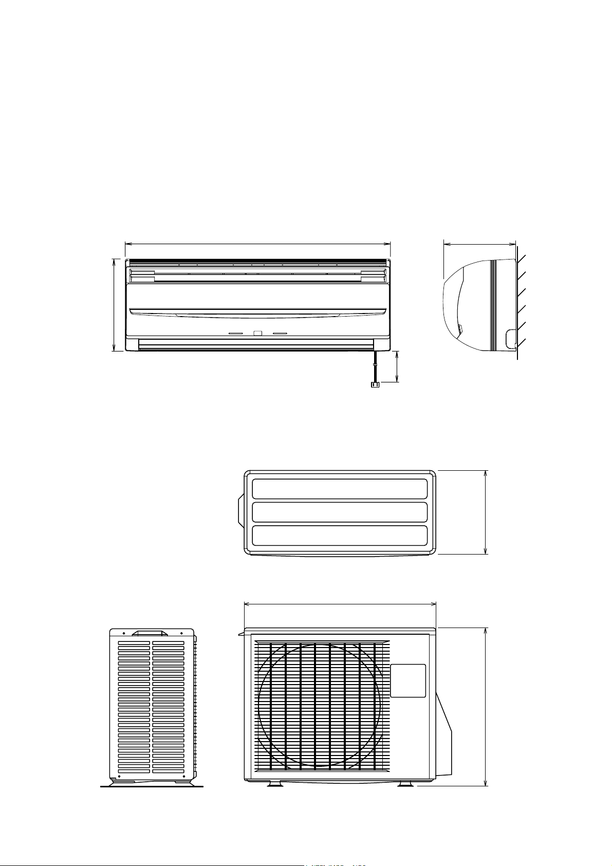
DIMENSIONS
Models :
ASHA07LCC / AOHR07LCC
ASHA09LCC / AOHR09LCC
( unit : mm )
INDOOR UNIT
275
215790
OUTDOOR UNIT
2,000
290
660
2006.04.24 2
540
Page 4
REFRIGERANT SYSTEM DIAGRAM
Models :
ASHA07LCC / AOHR07LCC
ASHA09LCC / AOHR09LCC
3-Way
valve
Muffler
Compressor
4-Way valve
Heat exchanger
( INDOOR )
2-Way
valve
Strainer
Expansion valve
Cooling
Heating
Refrigerant pipe diameter
Liquid : 1/4" (6.35 mm)
Gas : 3/8" (9.52 mm)
Heat exchanger
( OUTDOOR )
Strainer
2006.04.24 3
Page 5
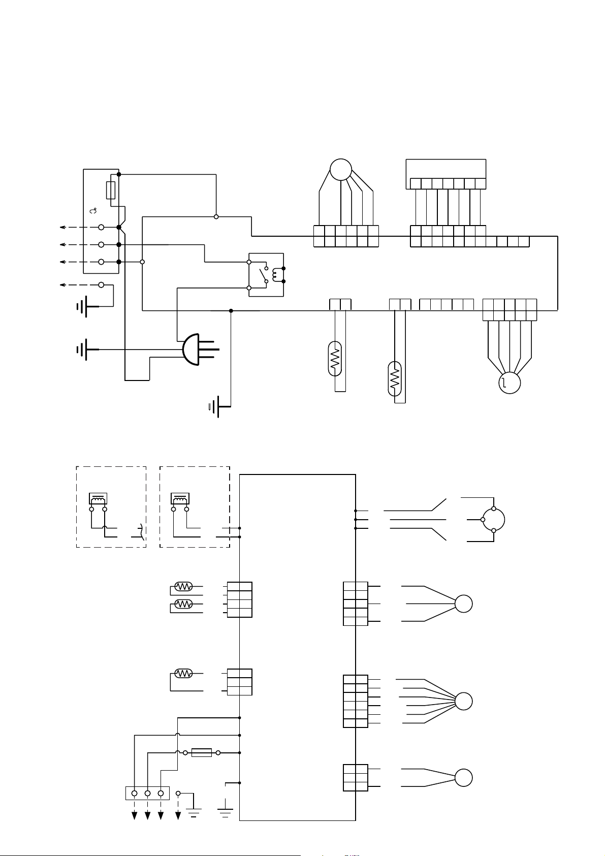
CIRCUIT DIAGRAM
Models :
ASHA07LCC / AOHR07LCC
ASHA09LCC / AOHR09LCC
INDOOR UNIT
TERMINAL
TO OUTDOOR UNIT
THERMAL
FUSE 102
N
L
3
RED
GREEN / YELLOW
BLUE
FAN MOTOR
F. M.
WHITE
YELLOW
WHITE
BLACK
RED
TM1
TM2
BLACK
3 4
POWER RELAY
4
5
6
4
5
6
CN2
BLUE
1
2
3
1
2
3
INDICATOR PCB
4
5
6
7
WHITE
6
7
10
11
3
WHITE
WHITE
WHITE
4
5
3
8
7
9
CN3
CN201
1
2
WHITE
WHITE
RED
1
2
4
5
6
1
2
3
CONTROLLER PCB
BROWN
L
W3
GREEN
CN4 CN5
1
2
BLACK
BLACK
ROOM TEMPERATURE
THERMISTOR
2
BLACK or GRAY
BLACK or GRAY
PIPE TEMPERATURE
THERMISTOR
3
TEST
CN7
1
2
4
5
1
CN6
1
2
4
5
3
1
2
4
5
3
ORANGE
YELLOW
BLUE
PINK
RED
N
POWER
SOURCE
M
STEP
MOTOR
OUTDOOR UNIT
Reactor Reactor
OR
WHITE
RED
Thermistor (pipe)
Thermistor (Discharge Pipe)
Thermistor (outdoor temp.)
BLACK BLACK
Terminal
Fuse 250V20A
3LN
WHITE
RED
BLACK
BLACK
BROWN
BROWN
BLACK
BLACK
RED
WHITE
GREEN
PCB (MAIN)
RED
W7
W10
W11
1
1
2
2
CN71
3
3
4
4
1
1
CN70
2
2
3
3
W4
W2
W1
W3
W8
W9
CN10
CN40
CN30
RED
WHITE WHITE
BLACK
BLACK
1
1
2
2
3
4
5
1
2
3
4
5
6
1
2
3
ORANGE
3
4
WHITE
5
RED
1
BROWN
2
BLUE
3
ORANGE
4
YELLOW
5
WHITE
6
BLACK
1
2
BLACK
3
S(V)
BLACK
FM
PMV
4WV
R(U)
CM
C(W)
Fan Motor
Expansion
Valve
4-Way
Valve Assy
Compressor
2006.04.24 4
Page 6
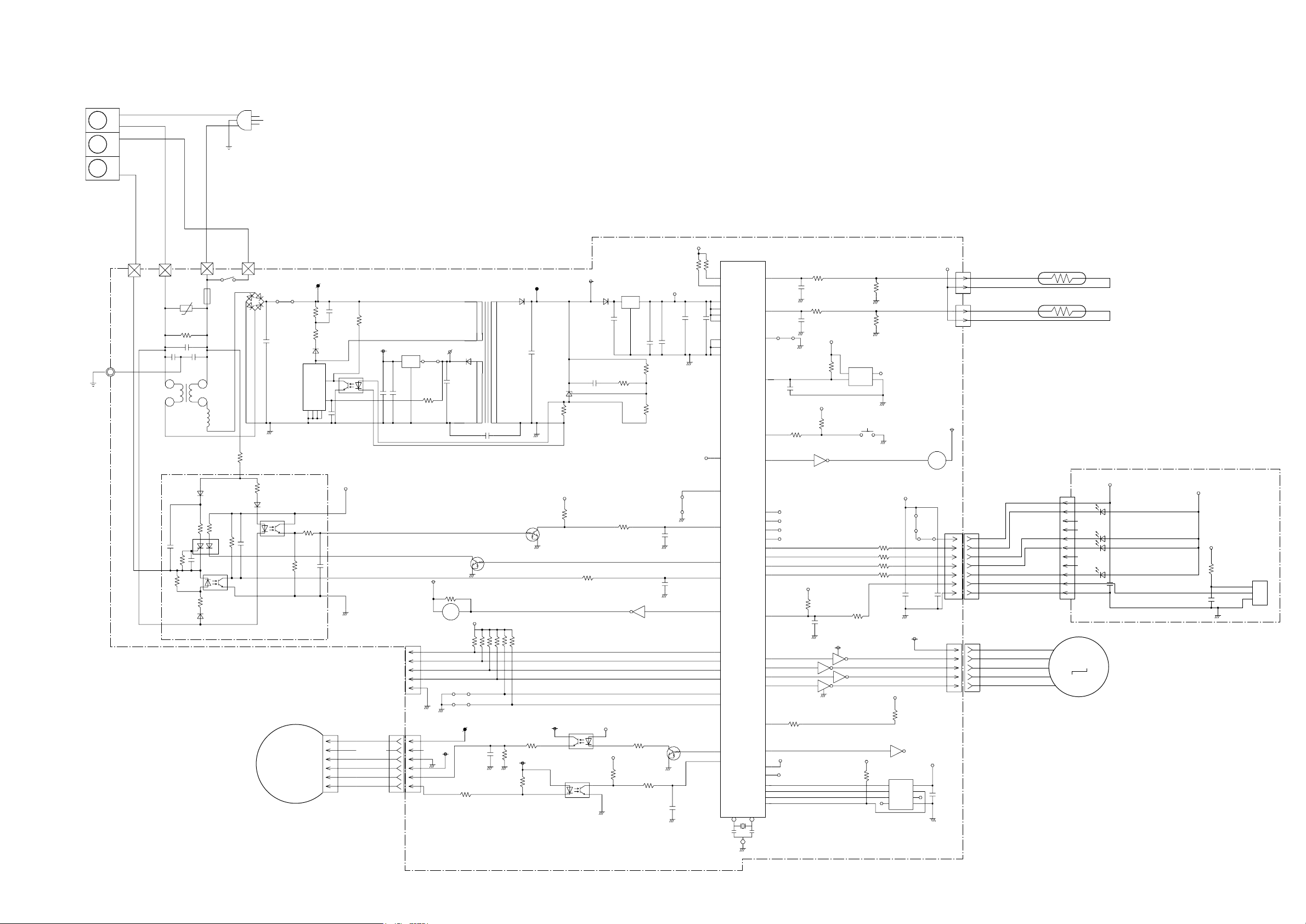
INDOOR PCB CIRCUIT DIAGRAM
Models : ASHA07LCC, ASHA09LCC
TERMINAL BOARD
N
L
3
UL1015
AWG22
GREEN
BLUE
GREEN /
YELLOW
E
BLACK
TM2
WHITE
RED
TM1
R60 330K
<1/2W>
VA1
470V
BROWN
F1
3.15A250V
K1
DW12D1
C1 0.34
C3
W3
GREEN
E
0.01
<F>
1.3A
9.0mH
L1
18
10
C2
0.01
<F>
T2
0.6A-10mH
R12
1.0K
<1/2W>
FAN MOTOR
POWER SOURCE
230V
50HZ
D1
GS I B460L
-E3/45
+
420V
I C 7 GK-LV3011E
14
F2
C4
100/
TNY264P
A
F. M.
<2W>
1NH42
I C2
100K
JM6
R3
5
EN/UV
S S S S
2 3
VM
D2
47
<1/4W>
D
BP
8
7
C5
0.01
4 4
3
1
I C3
PS2561-1
<L>
C6
0.1
<F>
5V
1
4
5
2
3
RED
BLACK
WHITE
YELLOW
BLUE CN2-1
TEST
R5
2M
<1/4W>
I C4
15V
78M15
3
O
C9
330/
25V
1
C10
2
0.1
+
<F>
PKM13EPY-4000-TF01
CN7
BS5P-SHF-1AA
CN7-1
CN7-2
CN7-3
CN7-4
CN7-5
CN2
CN2-6
CN2-4
CN2-3
CN2-2
53426-9920
G
2
<1/8W>
I
1
18K
12V
20V
JP7
+
R4
R43 10K
<1/8W>
B Z
BZ1
TIMER SHORT
CLOCK
DATA-OUT
DATA-IN
15V
A
ETS19AB1P8AG
D3
D1FL20U
C7
100/
35V
1
C11 0.01 <F>
Q2
DTC124EUA
5V
JM1
JM2
VM
C24
100/
16V
R23
6.8K
<1/4W>
CONTROLLER PCB ASSEMBLY
K02DR-0503HSE-C1
5V
R53 - R54
R8
47K
I C6
7805
I
G
10K <1/8W> x 2
O
C16
0.1
<F>
R9
34K
<1/8W>
1%
R10
8.25K
<1/8W>
1%
5V
C18
C19
+
10/
0.1
25V
<F>
C17
+
330/
25V
I C5
3
C
1
REF
A
2
R7
1.0K
<1/8W>
12V
C14
0.01
<B>
D5
D1F60
C15
330/
25V
+
<1/8W>
D4
D2FL20U
13.5V
+
C12
330/
25V
T1
10
6
4
2
TL431 I LP
5
7
5V
Q1
DTC124EUA
R13
10K
<1/8W>
R14
1.0K
<1/8W>
C22
C20
0.01
<B>
R15 1.0K <1/8W>
C21
0.01
<B>
I C3-7
10 7
R49 - R52, R47 - R48
10K <1/8W> x 6
REMOTE CONTROL UNIT CUSTOM CODE
AUTO RASTART
R26
820
<1/4W>
+
A
1%
A
<1/4W>
15V
R25
1.0K
1%
R22
4.7K
<1/8W>
15V
4 1
3
PS2561-1
1
2 3
I C10
PS2561-1
<L>
I C9
<L>
5V
R24
330
<1/8W>
2
Q4
DTC124EUA
5V
R21
10K
<1/8W>
4
R20
1.0K
<1/8W>
C23
1000P
<R>
I C 1
uPD780024ASGB-X70
-8ET-A
P23
P24
VDD0
VDD1
AVREF
AVDD
GND0
AGND
GND1
P47
P25
P01
I NTP1
P41
P40
P75
BUZ
P20
P03
P21
P22
P12
AN I 2
P13
AN I 3
P70
P02
I NTP2
33
P10
AN I 0
P11
AN I 1
I C
RESET
P42
P35
P57
P56
P55
P54
P53
P52
P51
P50
P00
I NTP0
P46
P45
P44
P43
P34
P36
XT1
XT2
P74
P73
P72
P71
X1
X2
32
X1
8.38MHz
17
18
10
20
26
27
9
21
34
52
19
36
46
45
44
14
38
15
16
23
22
39
37
25
24
31
28
47
12
35
51
50
49
48
11
13
30
29
43
42
41
40
8
7
6
5
4
3
2
1
C35
0.1
<F>
5V
JP1
C28
0.1
<F>
C31
0.1
<F>
R46
1.0K
<1/8W>
1000P
R55
1.0K
<1/8W>
C25
<R>
R38
1.0K
<1/8W>
R40
1.0K
<1/8W>
100K
<1/8W>
6 11
5V
R36
10K
<1/8W>
3
5
5V
S-80842CNNB
R42
-1383T2G
VDD
OUTNCGND
5V
R45
10K
<1/8W>
I C13-6
R30 330 <1/8W>
R29 330 <1/8W>
R28 330 <1/8W>
R27 330 <1/8W>
R37
<1/8W>
12V
9
2
15
14
4
13
12
8
R44
10K
<1/8W>
I C11
SW1
47
I C13-2
I C13-3
I C13-4
I C13-5
I C13-1
5V
R39
10K
<1/8W>
1%
R41
49.9K
<1/8W>
1%
5V
C26
+
100/
16V
12V
5V
R56
10K
<1/8W>
1
16
I C12
S-93C46BD0 I
-J8T1G
VCC
CS
DO
SK
D I
TEST
NC
GND
JM19
JP3
C27
0.01
<B>
K 1
5V
C36
0.1
<F>
5V
12V
CN4 2P-SAN
CN4-1 BLACK
CN4-2 BLACK
CN5 2P-SCN
CN5-1 GRAY
CN5-2 GRAY
CN3
S07B-ZR-3.4
RED
WHITE
WHITE
WHITE
WHITE
WHITE
WHITE
CN6
53325-0510
CN6-1 RED
CN6-2 ORANGE
CN6-3 YELLOW
CN6-4 PINK
CN6-5 BLUE
ROOM TEMPERATURE THERMISTOR
PIPE TEMPERATURE THERMISTOR
INDICATOR PCB ASSEMBLY
M
5V
D208 SLR-325 <ORANGE>
D205 SLR-325 <GREEN>
D204 SLR-325 <GREEN>
D201 SLR-325 <RED>
C201
0.1 <F>
LOUVER
CN201
JB20-11HG
CN201-1
CN201-2
CN201-3
CN201-4
CN201-5
CN201-6
CN201-7
CN201-8
CN201-9
CN201-10
CN201-11
K02CB-0300HSD-D0
5V
5V
R201 47
<1/4W>
+
C202
47/10V
I C201
GP1UM261RK
VCC
OUT
GND
2006.04.24 5
Page 7

OUTDOOR PCB CIRCUIT DIAGRAM
Models :
AOHR07LCC
AOHR09LCC
SERIAL
TERMINAL
INVERTER ASSEMBLY
AOHR07LCC : EZ-00506HUE
AOHR09LCC : EZ-0053HUE
REACTOR
EMI FILTER
COMPRESSOR
4-WAY VALVE
CONTROLLER PCB ASSEMBLY
AOHR07LCC : K05CS-0502HUE-C1
AOHR09LCC : K05CS-0500HUE-C1
2006.04.24 6
CN40
B6B-XARK-1-A
RED
AC FAN MOTOR
EXPANSION VALVE
Page 8

AC230V
50Hz
Models :
AOHR07LCC
AOHR09LCC
REACTOR
CONTROLLER PCB ASSEMBLY
AOYR07LCC : K05CS-0502HUE-C1
AOYR09LCC : K05CS-0500HUE-C1
IC200
FSBS10CH60
EXPANSION VALVE
THERMISTOR
HEAT EXCHANGE
DISCHARGE TEMP.
THERMISTOR
OUTDOOR TEMP.
2006.04.24 7
Page 9

ERROR CONTENTS
Models :
ASHA07LCC
ASHA09LCC
Error
Operation
LED
Display
Timer LED
Error
Serial signal error Off
Indoor unit thermistor error 2 flash
Outdoor unit thermistor error 3 flash
Indoor unit control error 4 flash
2 flash
3 flash
4 flash
5 flash
2 flash
3 flash
2 flash
3 flash
4 flash
2 flash
3 flash
4 flash
Serial signal (reverse) error, at operation start up
Serial signal (reverse) error, during oeration
Serial signal (forward) error, at operation start up
Serial signal (forward) error, during operation
Indoor temperature thermistor open / short
Heat exchanger middle thermistor open / short
Discharge thermistor open / short
Heat exchanger thermistor open
Outdoor temperature thermistor open / short
Forced automatic SW welded
Main relay welded
Power interruption error
Outdoor unit control error 5 flash
Indoor fan motor error 6 flash
Refrigerant cycle error 7 flash
Optional function error
Model information error
8 flash
0.1 sec on/off 0.1 sec on/off
7 flash
8 flash
2 flash
3 flash
5 flash
6 flash
2 flash
3 flash
2 flash
3 flash
4 flash
VDD permanent stop protection
reverse VDD permanent stop protection
Current trip error
CT abnormal
Compressor location detection error
Outdoor unit fan drive system abnormal
Abnormal lock
Abnormal rotation
Discharge Temperature abnormal
Cooling high pressure abnormal rise
PFC circuit error
Model information error
2006.04.24 8
Page 10

DISASSEMBLY ILLUSTRATION
Model : ASHA07LCC, ASHA09LCC
5
53
INVERTER
51
6
5
4
1
1
2
2006.04.24 9
3
7
Page 11

Model : ASHA07LCC, ASHA09LCC
48
236
26
188
28
32
52
31
24
29
27
39
46
20
30
61-2
188
37
36
40
38
42
33
21
61-1
2006.04.24 10
Page 12

Model : AOHR07LCC, AOHR09LCC
46
19
25
24
26
20
19
39
16
16
23
11
21
33
18
2006.04.24 11
Page 13

Model : AOHR07LCC, AOHR09LCC
32
45
29
10
41
38
28
27
2006.04.24 12
Page 14

Model : AOHR07LCC, AOHR09LCC
9
40
13
35
13
36
2006.04.24 13
Page 15

PARTS LIST
INDOOR UNIT
Part No.
Ref.
No.
20 Gear-A 9309994003
21 Casing Assy 9311354079
24 Crossflow Fan Assy 9307836015
26 Clamp (Motor) 9310102008
27 Shaft Holder-C Assy 9306628017
28 Drain Hose Assy 9314147012
29 Drain Cap Assy 9314493010
30 Wire Clamper 9311946014
31 Box (Switch) 9312908011
Description
ASHA07LCC
ASHA09LCC
1 Air Filter 9309997011
2 Filter (Electric) 9312153015
3 Filter (ION) 9311925033
Holder (Filter) 9306602017
54Clamper (Grille) 9306755010
6 Front Panel Total Assy 9313130183
7 Intake Grille Assy 9313131142
Ord.
Q'ty
32 Cover (Switch) 9312909018
33 Evaporator Total Assy 9313099015
36 Joint Pipe Assy 9313104016
37 Insulation (Pipe)-E 9304607007
38 Holder (Evaporator)-L 9309982017
39 Holder (Evaporator)-R 9309983014
40 Holder (Room Thermistor)
42 Air Seal
46 Step Motor 9900139025
48 Fan Motor Assy 9601814016
51 Remote Control Unit 9315027030
52 Bracket Panel 9310001004
53 Remote Control Unit Holder 9305642014
61-1 Flow Control Panel-U 9309991033
61-2 Flow Control Panel-Z 9309992030
188 Power Cord Assy
(Power Cord+Terminal)
236 Controller PCB Assy 9705656109
--- Pipe Temperature Thermistor 9702039042
--- Room Temperature Thermistor 9700801108
--- Indicator PCB Assy 9705039032
9310
9310611005
9900339036
(K02DR-0503HSE-C1)
2006.04.24 14
When you order parts, please make a photocopy of this page
and fill the number of the parts in the "Order" column.
Page 16

OUTDOOR UNIT
Ref.
No.
Description
Part No.
AOHR07LCC
AOHR09LCC
9 Cover (Case)
10 Bracket Valve
11 Cover (Switch)
13 Inverter Case Assy
16 Front Panel Assy
18 Propeller Fan
19 Bracket (Motor) Assy
20 Reactor Assy 9900357016
21 Separator Assy
23 Base Assy
24 Top Panel Assy
25 Cabinet Left Assy
26 Cabinet Right Assy
27 3-Way Valve Assy
28 2-Way Valve Assy
29 4-Way Valve Assy
32 Compressor Assy
33 Muffler 9308660015
35 PCB Holder 9331261012
36 Cover (Inverter Case)
38 Pulse Motor Valve Assy
39 Motor
40 Inverter PCB Assy (07) 9707078039
40 Inverter PCB Assy (09)
9331256018
9310229026
9310979013
9331279017
9331334013
9309909014
9331355018
9331392013
9331280013
9331332019
9313991036
9331336017
9331303019
9331301015
9331305013
9315206015
9331258012
9331317016
9602117017
9707078015
Ord.
Q'ty
41 Expansion Valve Coil
45 Solenoid
9900057039
9970055010
46 Condenser Assy 9331291019
--- Fuse Holder
--- Fuse
--- Thermister Holder Pipe
--- Thermistor Spring-A
--- Thermistor Spring
--- Terminal
--- Cord Clamp
--- Rubber Cushion
--- Nut Special Assy
--- Protective Net
--- Thermistor Assy
--- Thermistor (Outdoor Temp)
0501454012
0600382018
313714262805
313728262708
9300089012
9306489038
9307271014
9312680016
9313452018
9331262019
9900148034
9900210038
--- Emblem Rear 9315211019
2006.04.24 15
When you order parts, please make a photocopy of this page
and fill the number of the parts in the "Order" column.
Page 17

STANDARD
ACCESSORIES
Part No.
Name and Shape
Wall hook bracket
Remote control
unit
Remote control
unit holder
Battery (penlight)
INVERTER
ASHA07LCC
ASHA09LCC
9312752027
9315027030
9305642045
0600185527
Cloth tape
Tapping screw (big)
( 4 x 25)
Tapping screw (small)
( 3 x 12)
Air cleaning filter
Air cleaning filter
frame
9310519004
0700076046
0700019036
9312153015
9311925033
9306602017
2006.04.24 16
Page 18

0602G3038
 Loading...