

Page 1
SPLIT TYPE
ROOM AIR CONDITIONER
WALL MOUNTED
Models
Indoor unit Outdoor unit
ASH7FSBCW
ASH7USBCW
ASH7USBCW AOH7USNC
AOH7FSBC
AOH7USBC
type
CONTENTS
SPECIFICATIONS . . . . . . . . . . . . . . . . . . . . . . . . . . . . . . . . . . . . . . . . 1
DIMENSIONS . . . . . . . . . . . . . . . . . . . . . . . . . . . . . . . . . . . . . . . . . . . 2
REFRIGERANT SYSTEM DIAGRAM . . . . . . . . . . . . . . . . . . . . . . . . 3
CIRCUIT DIAGRAM . . . . . . . . . . . . . . . . . . . . . . . . . . . . . . . . . . . . . . 4
ERROR DISPLAY . . . . . . . . . . . . . . . . . . . . . . . . . . . . . . . . . . . . . . . .
DISASSEMBLY ILLUSTRATION . . . . . . . . . . . . . . . . . . . . . . . . . . . . 9
PARTS LIST . . . . . . . . . . . . . . . . . . . . . . . . . . . . . . . . . . . . . . . . . . .
15
6INDOOR PRINTED CIRCUIT BOARD CIRCUIT DIAGRAM . . . . .
8
Page 2
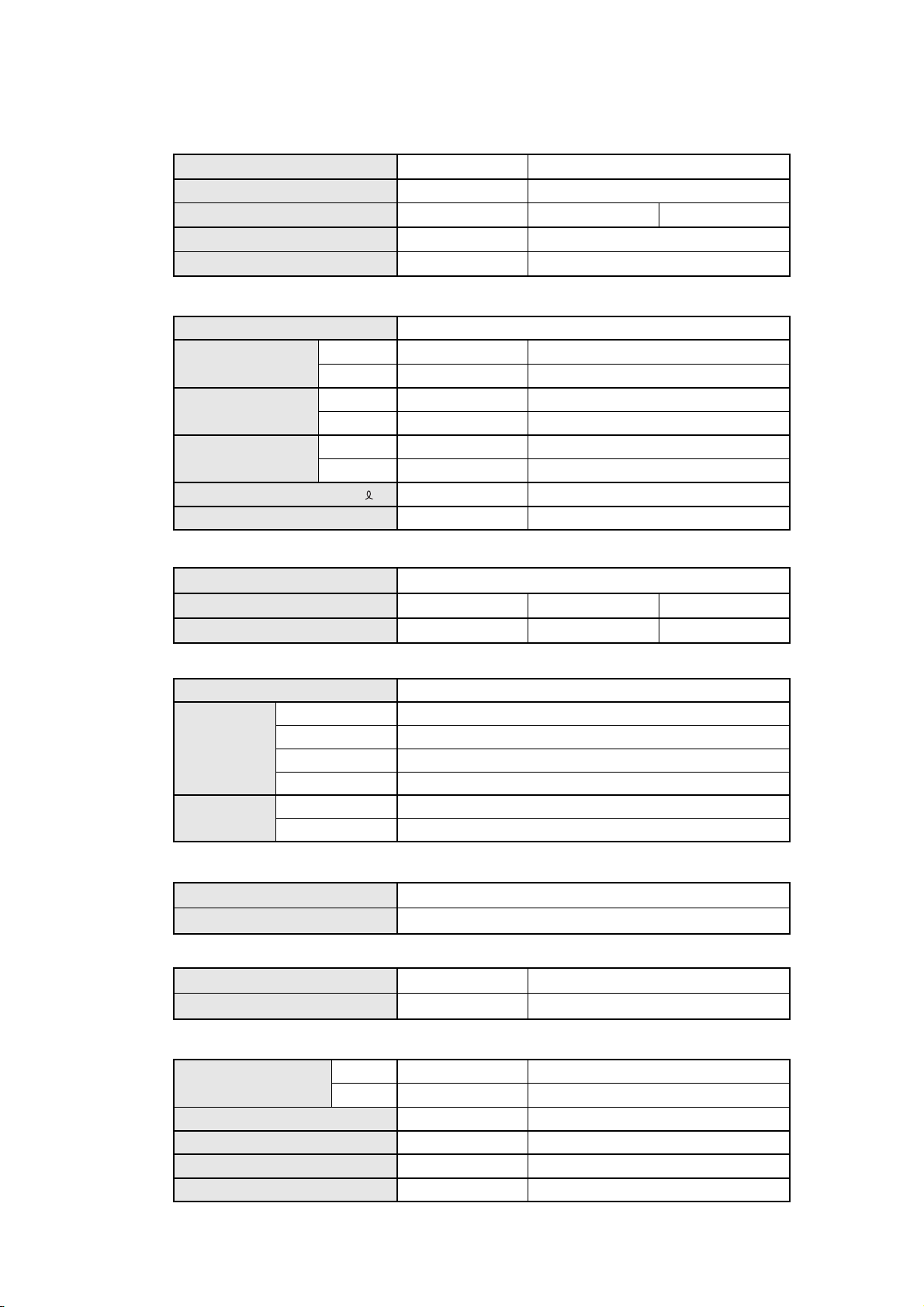
SPECIFICATIONS
TYPE
INDOOR UNIT
OUTDOOR UNIT
COOLING CAPACITY (kW)
HEATING CAPACITY (kW)
ELECTRICAL SPECIFICATIONS
POWER SOURCE
RUNNING
CURRENT
INPUT WATTS (kW)
EER (kW/kW)
MOISTURE REMOVAL
AIR CIRCULATION - Hi (m3/hr )
(A)
COOLIING
HEATING
COOLIING
HEATING
COOLIING
HEATING
( /hr )
COMPRESSOR
TYPE
DISCRIMINATION
REFRIGERANT R410
( g )
Cooling and Heat-pump heatingCooling
ASH7FSBCW
AOH7FSBC
2.25
-----
Single-phase 230V 50Hz
3.7
-----
0.80
-----
2.81
-----
1.0
380
802-100-35 (F) 802-100-35 (F) C-1RV096H1A
550
ASH7USBCW
AOH7USNCAOH7USBC
2.20
2.30
3.9
3.6
0.83
0.75
2.65
3.07
1.0
380
Rotary
600600
FAN MOTOR
POWER SOURCE (V)
DISCRIMINATION
INDOOR UNIT
OUTDOOR UNIT
HI-SPEED (r.p.m.)
MED-SPEED (r.p.m.)
LO-SPEED (r.p.m.)
DISCRIMINATION
HI-SPEED (r.p.m.)
DIMENSIONS
INDOOR UNIT
OUTDOOR UNIT
H x W x D (mm)
H x W x D (mm)
WEIGHT
INDOOR UNIT
OUTDOOR UNIT
GROSS / NET (kg)
GROSS / NET (kg)
REFRIGERANT CHARGE (R410)
FULL
CHARGE
ADDITIONAL CHARGE
CHARGELESS
MAX PIPE LENGTH
MAX ELEVATION
PIPE LENGTH
7.5 m
10.0m
10 / 8
27 / 25
550 g
600 g
20g / m
7.5 m
10 m
5 m
230
MFA-40GRL
1,280
1,170
1,060
MFB-07ATW
790
257 x 808 x 187
535 x 650 x 250
10 / 8
28 / 26
600 g
650 g
20g / m
7.5 m
10 m
5 m
2005.02.10 1
Page 3
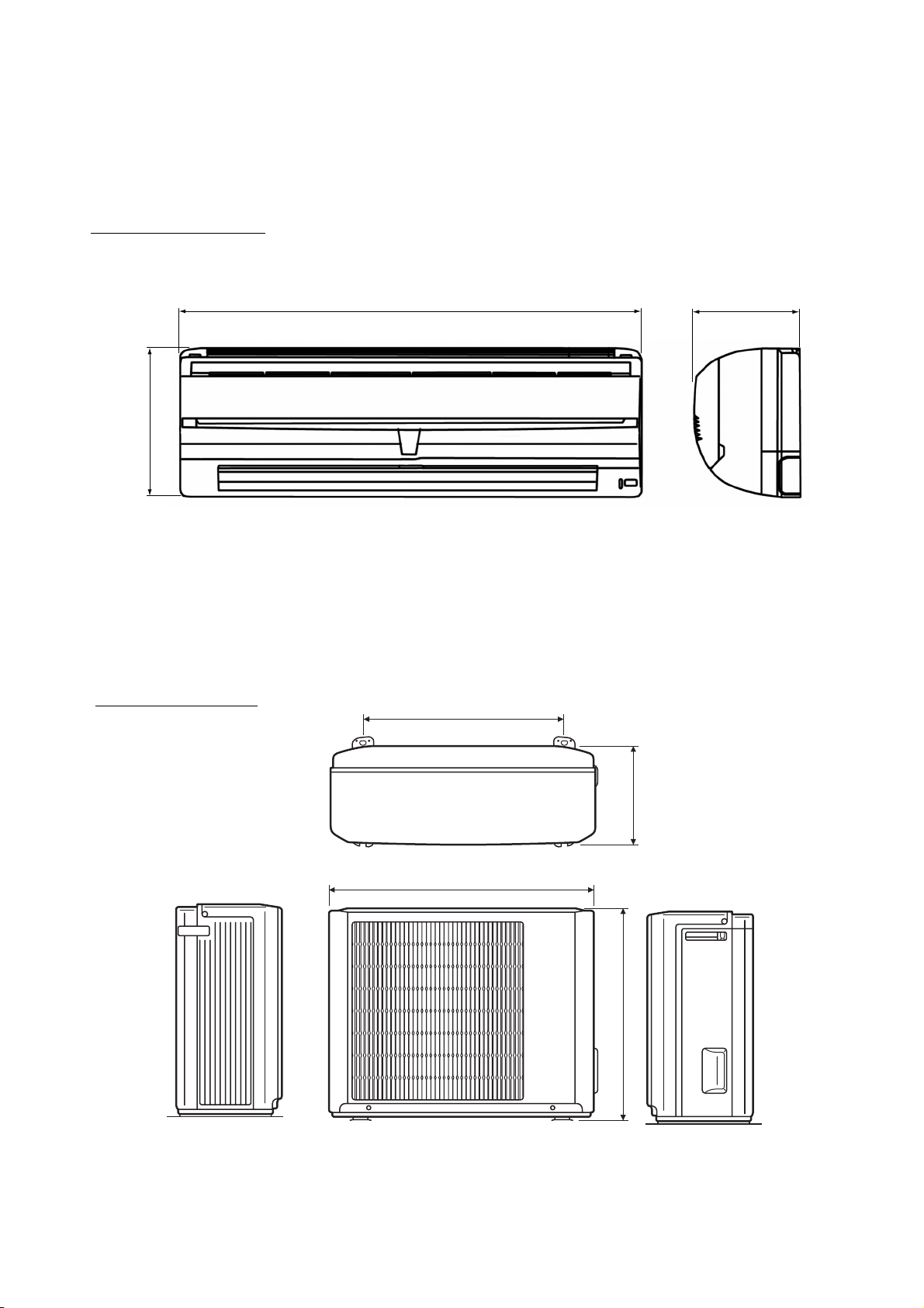
DIMENSIONS
Models : ASH7FSBCW
ASH7USBCW
257
U nit : m m
187808
Models : AOH7FSBC
AOH7USBC
AOH7USNC
500
250
650
535
2005.02.10 2
Page 4
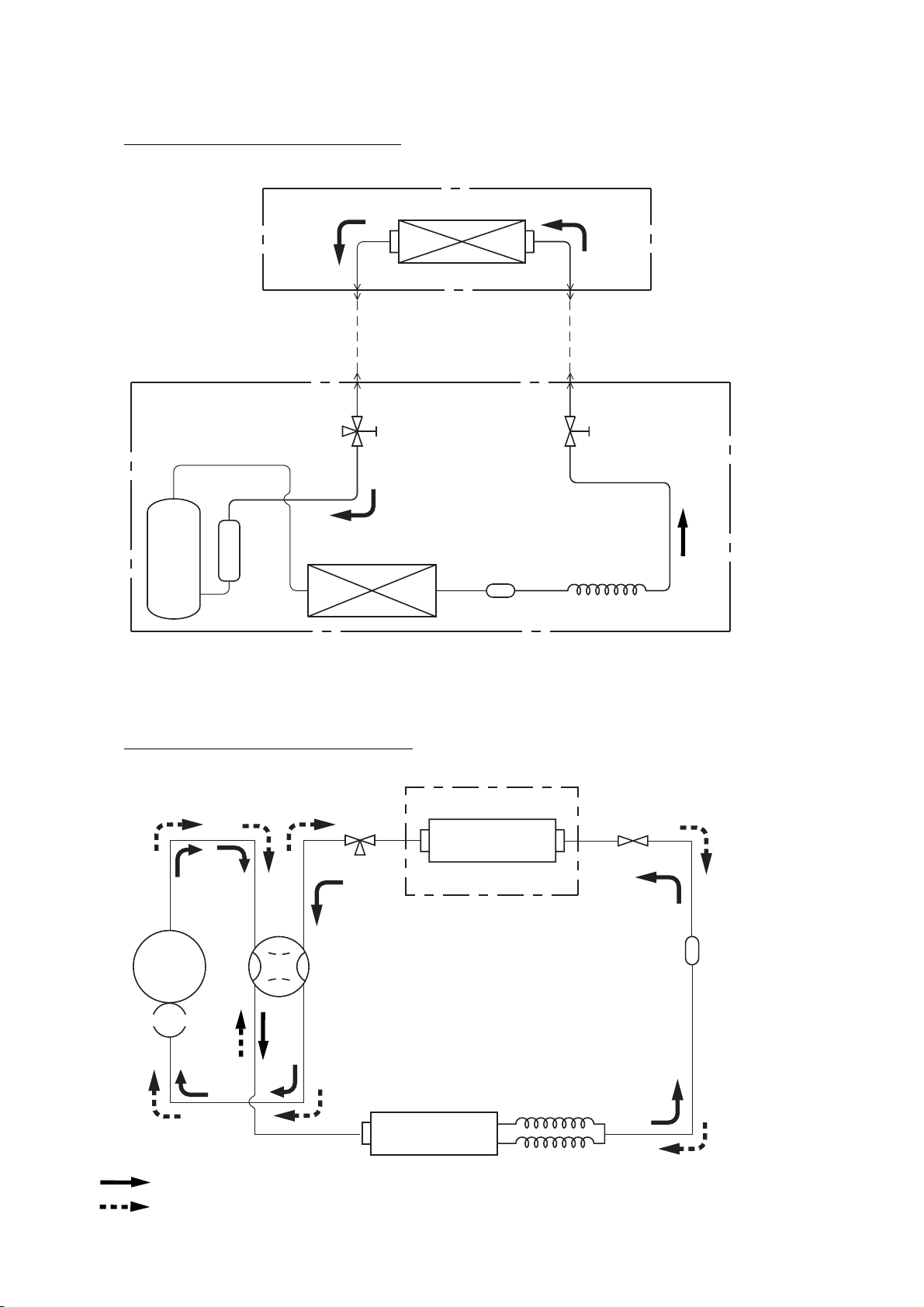
REFRIGERANT SYSTEM DIAGRAM
Models : ASH7FSBCW / AOH7FSBC
INDOOR UNIT
Evaporator
(Flare connection)
[ Connecting pipe ]
OUTDOOR UNIT
Compressor
Gas pipe (9.52 dia.)
(Flare connection)
3-Way valve
(with charging port)
Condenser
Models : ASH7USBCW / AOH7USBC
ASH7USBCW / AOH7USNC
(Flare connection)
Liquid pipe (6.35 dia.)
(Flare connection)
2-Way valve
Dryer
Capillary tube
Compressor
Accumulator
: Cooling
: Heating
3-Way valve
4-Way valve
INDOOR UNIT
Evaporator
2-Way valve
Dryer (AOY7USBC)
Strainer (AOY7USNC)
Condenser
Common capillary tube
2005.02.10 3
Page 5
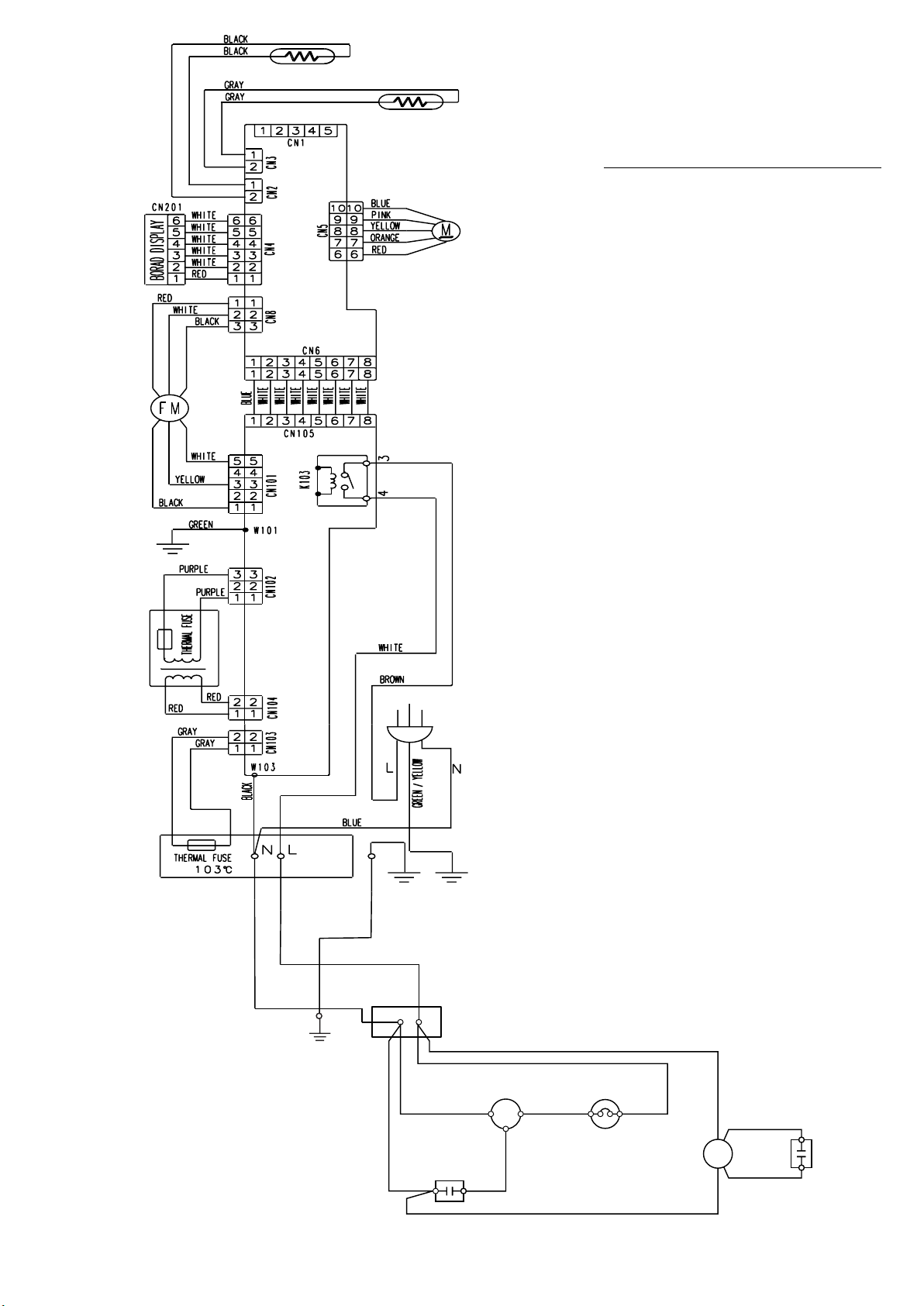
Thermistor
(room)
Fan Motor
Test
Relay
Thermistor
(pipe)
Step Motor
Controller PCB
CIRCUIT DIAGRAM
Models : ASH7FSBCW / AOH7FSBC
Transformer
Terminal
INDOOR UNIT
Power Supply PCB
OUTDOOR UNIT
Terminal
N L
BLACK
BLACK
WHITE BLUE
Compressor
Capacitor
WHITE RED
2005.02.10 4
Compressor
R C
CM
S
Overload Relay
WHITE
Fan Motor
FM
RED
ORANGE
Fan Motor
Capacitor
Page 6
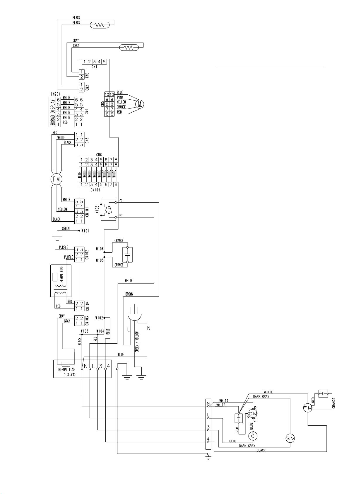
Fan Motor
Test
Thermistor
(room)
Thermistor
(pipe)
Stepping Motor
Controller PCB
Models :
ASH7USBCW / AOH7USBC
ASH7USBCW / AOH7USNC
Transformer
Relay
INDOOR UNIT
Fan Motor
Capacitor
Power Supply PCB
Terminal
2005.02.10 5
Terminal
Compressor
Capacitor
OUTDOOR UNIT
Compressor
Overload
Relay
Fan Motor
Capacitor
Fan Motor
4-way
Valve Coil
Page 7

INDOOR PCB CIRCUIT DIAGRAM
Model : ASH7FSBCW
POWER TRANSFORMER
EZ-030HSE-T
UL1015
AWG22
PRIMARY
W101
E
GREEN
F102
F101
TERMINAL BOARD
THERMAL FUSE
CN102-3 PURPLE
B2P3-VH-B
CN102
C102
4700P
FH101
T 3.15A 250V
CN102-1 PURPLE
VA101
470V
C101
4700P
C103
0.1
W103
BLACL
CN104-1 RED
SECONDARY
CN104-2 RED
B2B-XH-AM
CN104
BLACK
UL1015 AWG22
L
N
THERMAL FUSE (103 )
CN103-1 GRAY
CN103-2 GRAY
UL1015 AWG14
UL1015 AWG22
B2B-XASK-1-A
CN103
D101
S1VB20
WHITE
BLUE
GREEN / YELLOW
POWER SUPPLY PCB
EZ-002SWSE-P
FAN CAPACITOR
7.0 uF
12V
R102
1.0K
<1/2W>
+
D104
MTZJ15B
VA102
470V
Q101
2SD880
L101
SS11V-10062
R101
10K
<1/4W>
C105
2200
/35V
UL1015 AWG22
C104
0.1
+
C109
10/
50V
D102
1SR139
BROWN
POWER SOURCE
220 / 240V
50Hz
C110
B3P5-VH-B
CN101
SSR101
G3MC-201PL-VD DC12V
12V
IC101
D103
7805
1SR139
I
+ C108
C106
2200
/25V
K103
G4A-1A-E-PS
O
G
0.1
<F>
CN101-1
CN101-3
CN101-5
5V
12V
BLACK
YELLOW
WHITE
12V
CN105
PHR-8
FAN MOTOR
F M
CN105-1
CN105-2
CN105-3
CN105-4
CN105-5
CN105-6
CN105-7
CN105-8
UL1061 AWG26 x 8
CN7-1
CN7-2
CN7-3
BLUE
WHITE
WHITE
WHITE
WHITE
WHITE
WHITE
WHITE
RED
WHITE
BLACK
CN6-1
CN6-2
CN6-3
CN6-4
CN6-5
CN6-6
CN6-7
CN6-8
S3P-VH
5V
CN8
HEATING TEMPERATURE
CORRECTION 1
HEATING TEMPERATURE
CORRECTION 2
AUTO RESTART
REMOTE CONTROL
CUSTOM CODE
12V
CN6
B8B-PH-K-S
C1
0.1
<F>
5V
R1
10K <1/10W>
R6 1.0K
<1/8W>
C8
0.1
<F>
12
5V
C11
0.1
<F>
BZ1
12V
PKM13EPY-4000
B Z
R14
10K <1/10W>
JP1
JP2
JP3
JP4
Q1 DTC124EUA
3
2
R7 4.7K
<1/8W>
11
IC4-5 uLN2003
5
10
IC2
BR93LC46
8
VCC
4
D0
TEST
6
GND
5
EEPROM
1
Q3 DTC124EUA
123
IC4-6 uLN2003
6
IC4-7 uLN2003
7
1
CS
SK
2
D1
3
NC
7
CONTROLLER PCB ASSEMBLY ( MAIN PCB )
EZ-003TWSE-C ( F )
I C 1
R30 1.0K
<1/10W>
8
P75
P02
P20
P21
P22
P74
AVDD
VDD0
VDD1
AVREF
P12
P13
XT1
VSS0
VSS1
AVSS
P53
P01
P50
P51
P52
P73
P72
P71
P70
P23
P24
I C
X1 X2
33
P57
RESET
P11
P10
XT2
P25
P36
P03
P35
P34
P00
P56
P55
P54
P47
P46
P45
P44
P43
P42
P41
P40
32
2
28
C25
0.1
<F>
24
C22
0.1
<F>
25
C21
0.1
<F>
29
19
13
38
12
11
35
C16
1000P
<R>
7
6
5
52
51
50
49
48
47
46
45
X1
CST8.38MHz
R25 390
<1/10W>
R24 390
<1/10W>
5V
12V
9
1
2 15
3 14
4
5V
16
44
37
14
15
16
43
27
10
20
26
23
22
30
9
34
21
4
36
1
2
3
5V
42
41
40
39
17
18
31
R2 1.0K
<1/10W>
5V
R3, R34, R5, R35
10K <1/10W>
R33 10K
<1/10W>
Q2
DTC124EUA
321
C7
10/
25V
5V
R8 10K
<1/10W>
R12 10K
<1/10W>
uPD780024ASGB-X26-8ET
C2
0.1
<F>
+
C9 0.01
<R>
5V
5V
R29 10K
<1/10W>
R28 10K
<1/10W>
RESET
4
IC3
BD4742G
R20 - R23
10K <1/10W> x 4
R19 10K
<1/10W>
R17 330 <1/10W>
R16 330 <1/10W>
R15 330 <1/10W>
13
8
SW1
5V
5
2
1
3
R18 47
<1/10W>
IC4-1 uLN2003
IC4-2 uLN2003
IC4-3 uLN2003
IC4-4 uLN2003
MANUAL AUTO
SWITCH
C27
0.1
<F>
R27
10K (1%)
<1/10W>
R26
49.9K (1%)
<1/10W>
5V
12V
5V
CN2
CN3
CN1
CN5 53325-0510
150-103-86176
CN2-1 BLACK
CN2-2 BLACK
CN3-1 GRAY
CN3-2 GRAY
150-503-96077
B5P-SHF-1AA
CN1-1
CN1-2
CN1-3
CHECKER
CN1-4
CN1-5
B6B-PH-K-SCN4
CN4-1 RED
CN4-2 WHITE
CN4-3 WHITE
CN4-4 WHITE
CN4-5 WHITE
CN4-6 WHITE
UL1061 AWG26 x 6
CN5-6 RED
CN5-7 ORANGE
CN5-8 YELLOW
CN5-9 PINK
CN5-10 BLUE
UL1061 AWG26 x 5
ROOM TEMPERATURE THERMISTOR
PIPE TEMPERATURE THERMISTOR
INDICATOR PCB
EZ-002SWSE-D
R201 47
C202
0.1
<F>
OPERATE
TIMER
SWING
CN201
<1/4W>
C201
47/10V
D201 SLR-325<VC>RED
D202 SLR-325<MC>
GRN
ORG
D203 SLR-325<DC>
+
GP1UM261RK
DATA
LOUVER
1
2
3
4
5
6
X201
VCC
GND
5V
2005.02.10 6
Page 8

Model : ASH7USBCW
POWER TRANSFORMER
EZ-030HSE-T
THERMAL FUSE
PURPLE
PRAIMARY
CN102-3
RED
PURPLE
RED
CN104-1
CN102-1
CN104-2
B2P3-VH-B
CN102
GREEN
C102
4700P
C103
0.1
VA101
470V
C101
4700P
FH102
F101
T
3.15A 250V
FH101
BLACK
BLACK
UL1015 AWG22
TERMINAL BOARD
N L 3 4
OUTDOOR UNIT
)
(103
THERMAL FUSE
GRAY
SECONDARY
B2B-XH-AM
GRAY
CN103-1
POWER SUPPLY PCB
CN103-2
EZ-002YHSE-P
B2B-XASK-1-A
W105
CN104
K101
G5NB-1
CN103
L101
SS11V-10062
C104
0.1
12V
CR101 120/0.2
D101
S1VB20
12V
BROWN
WHITE
BROWN
BLUE
UL1015 AWG22
RED
UL1015 AWG22
G3MB-202P UTU
C110
4700P
VA103
470V
W102W104W103
BLUERED
BLUE
UL1015 AWG14
UL1015 AWG22
UL1015 AWG22
VA102
470V
12V
ORANGE
ORANGE
7.0
FAN CAPACITOR
UL1015 AWG20
UL1015 AWG20
W106
CN101
SSR101
G3MC-201PL-VD
12V
D103
1SR139
C106
2200
/25V
D102
1SR139
K 101
K103
G4A-1A-E-PS
B3P5-VH-B
IC101
7805
I
G
+
O
C108
0.1
<F>
CN101-1
BLACK
CN101-3
YELLOW
CN101-5
WHITE
5V
12V
FAN MOTOR
12V
CN105
PHR-8
F M
CN105-1
CN105-2
CN105-3
CN105-4
CN105-5
CN105-6
CN105-7
CN105-8
UL1061 AWG26 x 8
CN7-1
RED
CN7-2
WHITE
CN7-3
BLACK
BLUE
WHITE
WHITE
WHITE
WHITE
WHITE
WHITE
WHITE
CN6-1
CN6-2
CN6-3
CN6-4
CN6-5
CN6-6
CN6-7
CN6-8
5V
CN8
S3P-VH
HEATING TEMPERATURE
CORRECTION 2
12V
CN6
B8B-PH-K-S
5V
R1 10K
<1/10W>
C1
0.1 <F>
HEATING TEMPERATURE
CORRECTION 1
R6 1.0K
<1/8W>
C8
0.1
<F>
12
C11
0.1
<F>
5V
BZ1
12V
PKM13EPY-4000
R14 10K
<1/10W>
10K <1/10W>
JP1
JP2
JP3
JP4
Q1
DTC124EUA
3 1
2
R7 4.7K
<1/8W>
IC4-5 uLN2003
5
IC2
BR93LC46
8
VCC
D0
4
TEST
6
GND
5
EEPROM
B Z
Q3
DTC124EUA
1
11 6
10
1
CS
2
SK
3
D1
7
NC
CONTROLLER PCB ASSEMBLY (MAIN PCB)
EZ-0030AHSE-C (F)
I C 1
uPD780024ASGB-X25-8ET
321
5V
R8 10K
<1/10W>
5V
C7
10/
25V
+
C2
0.1
<F>
C9
0.01
<R>
44
37
14
15
16
43
27
10
20
26
23
22
30
9
34
21
4
36
1
2
3
5V
42
41
40
39
17
18
31
AVDD
VDD0
VDD1
AVREF
P12
P13
XT1
VSS0
VSS1
AVSS
P53
P01
P50
P51
P52
P73
P72
P71
P70
P23
P24
I C
X1 X2
33
P57
RESET
P11
P10
XT2
P25
P36
P03
P35
P34
P00
P56
P55
P54
P47
P46
P45
P44
P43
P42
P41
P40
32
2
R30 1.0K
<1/10W>
8
28
C25
0.1
<F>
24
C22
0.1
<F>
25
C21
0.1
<F>
29
19
13
38
12
11
35
7
6
5
52
51
50
49
48
47
46
45
X1
CST8.38MHz
R2 1.0K
<1/10W>
5V
3
2
IC4-6 uLN2003
IC4-7 uLN2003
7
Q2
DTC124EUA
R3,R34,R5,R35
JP1
R33 10K
<1/10W>
R12 10K
<1/10W>
12V
1
3
R25 390
<1/10W>
R24 390
<1/10W>
R24 390
<1/10W>
5V
C16
1000P
<R>
9
2
4 13
5V
R29 10K
<1/10W>
R28 10K
<1/10W>
RESET
IC3
BD4742G
5V
R20 - R23
10K <1/10W> x 4
R19 10K
<1/10W>
IC4-1 uLN2003
16
IC4-2 uLN2003
15
IC4-3 uLN2003
14
IC4-4 uLN2003
8
R17
R16
R15
4
5V
5
3
R18 47
<1/10W>
SW1
C27
2
0.1
1
<F>
330 <1/10W>
330 <1/10W>
330 <1/10W>
MANUAL AUTO
SWITH
5V
R27
10K
<1/10W>
(1%)
R26
49.9K
<1/10W>
(1%)
5V
12V
CN2 150-103-86176
CN2-1 BLACK
CN2-2 BLACK
CN3-1 GRAY
CN3-2 GRAY
CN3 150-503-96077
CN1
B5P-SHF-1AA
CN1-1
CN1-2
CN1-3
CHECKER
CN1-4
CN1-5
CN4 B6B-PH-K-S
CN4-1
RED
WHITE
CN4-2
WHITE
CN4-3
CN4-4
WHITE
WHITE
CN4-5
WHITE
CN4-6
UL1061 AWG26 x 6
CN5 53325-0510
CN5-6
CN5-7
CN5-8
CN5-9
CN5-10
UL1061 AWG26 x 5
ROOM TEMPERATURE THERMISTOR
PIPE TEMPERATURE THERMISTOR
INDICATOR PCB
EZ-002YHSE-D
R201
C202
0.1
<F>
OPERATE
RED
TIMER
GREEN
SWING
ORANGE
CN201
47 <1/4W>
47/10V
C201
D201 SLR-325 <VC>
D202 SLR-325 <MC>
D203 SLR-325 <DC>
RED
ORANGE
YELLOW
PINK
BLUE
1
2
3
4
5
6
+
DATA
LOUVER
X201
VCC
GP1UM261RK
GND
5V
POWER SOURCE
220 / 240V
TO EARTH TERMINAL
GREEN / YELLOW
50Hz
2005.02.10 7
Page 9

ERROR DISPLAY
Troubleshooting check table
Operation lamp
: Red lamp
Timer lamp : Green lamp
Small division indicationLarge division indication
Error contents Error contents
thermistor error Red lamp
control unit error Red lamp (4 times) MANUAL AUTO button error Red lamp
(indoor unit ) Green lamp
fan motor error Red lamp (6 times) lock error Red lamp
(indoor unit) Green lamp
LED indication LED indication
(2 times) thermistor error (room temp.) Red lamp
Green lamp Green lamp (2 times)
thermistor error (heat exchanger) Red lamp
Green lamp (3 times)
Green lamp
power source Hz decision error Red lamp
Green lamp (4 times)
Green lamp
r.p.m error Red lamp
Green lamp (3 times)
: 0.5s ON/OFF repeated
: 0.1s ON/OFF repeated
(2 times)
(2 times)
2005.01.31 8
Page 10

DISASSEMBLY ILLUSTRATION
Model : ASH7FSBCW
ASH7USBCW
2005.02.10 9
Page 11

Model : ASH7FSBCW
151
401
233
875
235
196
158
108
184
652-1
178
466
188
236
815
872
687
385
873
874
127
164
109
876
281
668
767-1
178
28
146
764
169
522-1
122
523
283
323
65
69
440
323
2005.02.10 10
Page 12

Model : ASH7USBCW
151
401
233
875
235
196
158
108
184
652-1
178
466
188
236
815
872
687
385
873
34
127
164
109
876
874
281
668
767-1
178
28
146
764
169
522-1
122
523
283
323
65
69
440
323
2005.02.10 11
Page 13

Model : AOH7USNC
7
13
423
14
26
15
19
9
195
688
982
815
26
196-2
246
47-2
26
916
16
26
230
781
46
55
138
365
12
935
942-2
38
37
32
34
42
942
62
48
41
39
986
985
5
674
4
2005.02.10 12
Page 14

Model : AOH7USBC
2005.02.10 13
Page 15

Model : AOH7USNC
2005.02.10 14
Page 16

PARTS LIST
INDOOR UNIT
Ref.
No.
28 Blower Cover 9306462000
34 Capacitor(Fan Motor)
63 Front Panel Assy 9312172085
65 Flow Control Panel-Z 9306058043
69 Louver-A 9306055028
74 Filter 9305444014
108 Base 9309755062
109 Casing 9306052027
122 Shaft Holder-B 9303066010
127 Drain Hose Assy 9305550029
146 Evaporator Assy 9308559036
151 Control Box
158 Connecting Pipe Assy 9306416010
164 Fan Motor Assy-IN
169 Cross-Flow Fan Assy
178 Motor Cushion-M 9601302018
184 Thermistor Spring
188 Power Cord Assy 9704097033
196 Clamp SKB-150
233 Power Transformer 9701803026
Description
ASH7FSBCW ASH7USBCW
9900133016
9330007017
9601172017
9307836015
313728262708
313035356905
Part No.
9306462000
9900089061
9312172085
9306058012
9306055028
9305444014
9309755062
9306052027
9303066010
9305550029
9308559036
9330007017
9306416010
9601172017
9305435012
9601302018
313728262708
9702595043
313035356905
9701803026
Ord.
Q'ty
235 Thermistor Assy-Pipe 9702039059
236 Controller PCB Assy 9704865175
240 Remote Control Unit 9312058037
281 Clamp Metal(Pipe) 9306063009 9306063009
283 Bushing-A 9303529010
323 Louver-B 9306056025
385 Indicator PCB Assy 9704921017
401 Wall Hook Bracket 9304358008
440 Flow Control Panel-U 9306057046
466 Clamp NK-4N 313714328805
522-1 Gear-A 9306062002
523 Gear Bracket 9306407001
652-1 Thermistor Holder Pipe 313714262805
687 Earth Terminal 9330012011
688 Screw w/Washer 313681304205
759 Intake Grille 9330002012
764 Drain Cap Assy 9304150008
767-1 Bottom Cover 9330004016
777 Clamper(Grille) 9306755010 9306755010
815 Terminal 9900040062
850 Window (Receiver) 9330003019
872 Indicator Case 9330009011
873 Lamp Cover 9330014015
874 Control Box Cover 9330008014
875 Power Supply PCB 9704918017
876 Step Motor 9900139018 9900139018
9702039059
9704865168
9312058020
9303529010
9306056025
9704920010
9304358008
9306057015
313714328805
9306062002
9306407001
313714262805
9330012011
313681304205
9330002012
9304150008
9330004016
9900040048
9330003019
9330009011
9330014015
9330008014
9704917010
2005.02.10 15
When you order parts, please make a photocopy of this page
and fill the number of the parts in the "Order" column.
Page 17

OUTDOOR UNIT
Ref.
Description
No.
4
Emblem-Rear
5
Cabinet Front Panel, Plastic
7
Connector Cover
9
Cabinet Rear Panel, Plastic
12
Base Assy, Painted
13
3-Way Valve
14
2-Way Valve
15
Dryer
16
Condenser Assy
19
Capillary Tube Assy
26
BR Sheet 80 x 50 x T2
BR Sheet 110 x 130 x T2
BR Sheet 30 x 120 x T7
32
Control Box Metal
34
Capacitor (Fan Motor)
37
Capacitor (Running)
38
Clamp Metal (Capacitor)
39
Propeller Fan
41
Fan Motor Assy-Out
42
Bracket (Motor)
46
Compressor Assy
47-2
Rubber (Discharge Pipe)
55
Special Nut M8
62
Wire Assy (Shield)-A
98
Fan Ring
138 9306474003Separate Wall Metal
195
Clamp SKB-100
196-2
Clamp SKB-3MC
230
Overload Relay
Part No.
AOH7FSBC
9308474018
9306016012
9306018016
9306017019
9304806059
9312863013
9312862016
9312056002
9309065024
9313013011
9305039180
9305039197
9305039036
9306475024
9700467045
9307588082
313468061808
9306565015
9601371014
9306021016
9313009014
313185159802
9307615016
9305695027
9306019020
313361275805
9305335008
9309128002
Ord.
Ref.
Q'ty
138 Separate Wall Metal 9306474003
195 Clamp SKB-100 313361275805
196-2 Clamp SKB-3MC 9305335008
230 Overload Relay 9309128002
343 Solenoid Coil 9970003011
344 4-Way Valve 9900162016
345 4-Way Valve Assy 9313017019
365 Bracket (Valve) 9306020026
420 Capillary Assy 9313011017
Description
No.
4
Emblem-Rear 9308474018
5
Cabinet Front Panel, Plastic 9306016012
7
Connector Cover 9306018016
9
Cabinet Rear Panel, Plastic 9306017019
12
Base Assy, Painted 9304806042
13
3-Way Valve 9312863013
14
2-Way Valve 9312862016
16
Condenser Assy 9309104020
32 Control Box Metal 9306475024
34 Capacitor (Fan Motor) 9900089023
37 Capacitor (Running) 9307588082
38 Clamp Metal (Capacitor) 313468061808
39 Propeller Fan 9306565015
41 Fan Motor Assy-Out 9601371014
42 Bracket (Motor) 9306021016
46 Compressor Assy 9313009014
48 Fan Ring 9306019013
55 Special Nut M6 9307615016
62 Wire Assy (Shield)-A 9305791026
AOH7USBC
Part No.
AOH7USNC
9308474018
9306016012
9306018016
9306017019
9304806042
9312863013
9312862016
9309104020
9306475024
9900089023
9307588082
313468061808
9306565015
9601371014
9306021016
9314516016
9306019013
9307615016
9305791026
9306474003
313361275805
9305335008
9309658004
9970003011
9900162016
9313017019
9306020026
9313011017
Ord.
Q'ty
246
Outlet Pipe (Cond.)
365
Bracket (Valve)
423
Noise Insulation-F
688
Screw w/Washer
781
Rubber Cushion
815
Terminal-2P
916
Noise Insulation-A
935
Reinforcement Plate
942
Control Box Cover Metal
942-2
Control Box Cover-B Metal
982
Cord Clamp, Plastic
985
Special Nut w/Washer
986
Special Washer
9308669001
9306020040
9306937010
313681304205
9312680016
9306489014
9313028008
9306473006
9306476007
9305975006
9302271002
9304902003
9304903000
423 Noise Insulation-F 9306937010
688 Screw w/Washer 313681304205
765 Drain Pipe (L-type)
766 Drain Pipe Packing
781 Rubber Cushion 9312680016
815 9306488017
Terminal-4P
916 9313028008
Noise Insulation-A
935 Reinforcement Plate 9306473006
Control Box Cover Metal
942 9306476007
942-2 Control Box Cover-B Metal 9305975006
982 Cord Clamp, Plastic 9302271002
985 Special Nut w/Washer 9304902003
986 Special Washer 9304903000
987 Muffler A ---
2005.02.10 16
9306937010
313681304205
9301102000
9301143003
When you order parts, please make a photocopy of this page
and fill the number of the parts in the "Order" column.
9301102000
9301143003
9312680016
9306488017
9313028008
9306473006
9306476007
9305975006
9302271002
9304902003
9304903000
9305865000
Page 18

STANDARD ACCESSORIES
Name and Shape
ASH7FSBCW
Wall hook bracket
Part No.
ASH7USBCW
Remote control
unit
Battery (penlight)
Tapping screw
O
( 4 x 25 )
Cloth tape
Drain pipe
(Including drain packing)
9304358008
9312058037
0600185534
0700076046
9308117007
9304358008
9312058020
0600185534
0700076046
9308117007
9303029015
2005.02.10 17
Page 19

0311G2409
 Loading...