

Page 1
SPLIT TYPE
ROOM AIR CONDITIONER
WALL MOUNTED
Models
Indoor unit Outdoor unit
ASH14LSBCW AOH14LFBC
ASH18LSBCW AOH18LFBC
type
CONTENTS
SPECIFICATIONS . . . . . . . . . . . . . . . . . . . . . . . . . . . . . . . . . . . . . . . . 1
DIMENSIONS . . . . . . . . . . . . . . . . . . . . . . . . . . . . . . . . . . . . . . . . . . . 2
REFRIGERANT SYSTEM DIAGRAM . . . . . . . . . . . . . . . . . . . . . . . . 3
CIRCUIT DIAGRAM . . . . . . . . . . . . . . . . . . . . . . . . . . . . . . . . . . . . . . 4
ERROR CONTENTS . . . . . . . . . . . . . . . . . . . . . . . . . . . . . . . . . . . . . 5
INDOOR PRINTED CIRCUIT BOARD CIRCUIT DIAGRAM . . . . . 7
OUTDOOR PRINTED CIRCUIT BOARD CIRCUIT DIAGRAM . . . 8
DISASSEMBLY ILLUSTRATION . . . . . . . . . . . . . . . . . . . . . . . . . . . 11
PARTS LIST . . . . . . . . . . . . . . . . . . . . . . . . . . . . . . . . . . . . . . . . . . . 14
STANDARD ACCESSORIES
. . . . . . . . . . . . . . . . . . . . . . . . . . . . .
15
Page 2
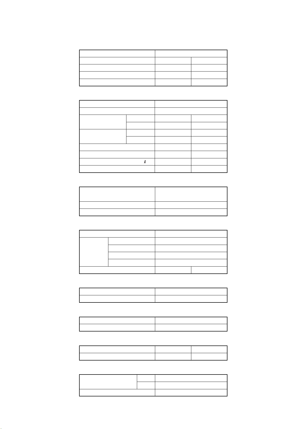
SPECIFICATIONS
TYPE
INDOOR UNIT
OUTDOOR UNIT
COOLING CAPACITY
HEATING CAPACITY
(kW) 5.20
(kW)
COOL & HEAT INVERTER
ASH14LSBCW
AOH14LFBC
4.20
5.60
ELECTRICAL DATA
POWER SOURCE (V) 230
FREQUENCY (Hz)
RUNNING CURRENT
INPUT WATTS
E.E.R.
COP HEATING
MOISTURE REMOVAL
AIR CIRCULATION-Hi (m /hr)
(kW/kW)
(kW/kW)
COOLING 7.6
(A)
HEATING
COOLING 1.72
(kW)
HEATING
COOLING
( /hr)
3
4.9
6.4
1.11
1.45
3.78
3.86
2.1
50
COMPRESSOR
TYPE
DISCRIMINATION DA / 30A / F-25F
REFRIGERANT R410A (g) 1,150
Hermetic type, 4 pole, 3 phase,
DC inverter motor, Rotary
ASH18LSBCW
AOH18LFBC
6.25
7.6
1.73
3.02
3.61
2.8
C 700 H700C 700 H700
FAN MOTOR
POWER SOURCE (V) 230
HI-SPEED (r.p.m.) C 1,480 H 1,480
INDOOR
UNIT
OUTDOOR UNIT (r.p.m.) C 860 H 820C 820 H 750
MED-SPEED (r.p.m.) C 1,260 H 1,300
LO-SPEED (r.p.m.) C 1,040 H 1,110
QUIET (r.p.m.) C 850 H 950
DIMENSIONS
INDOOR UNIT
OUTDOOR UNIT
H x W x D (mm)
H x W x D (mm)
275 x 790 x 215
578 x 790 x 300
WEIGHT
INDOOR UNIT
OUTDOOR UNIT
GROSS / NET (kg)
GROSS / NET (kg)
NOISE LEVEL
INDOOR UNIT
OUTDOOR UNIT
(dB) C 45 H 43
(dB) C 49 H 49
C 44 H 43
C 48 H 48
REFRIGERANT (R410A)
FULL CHARGE AMOUNT
PIPE LENGTH
ADDITIONAL REFRIGERANT
15 m 1,150 g
20 m 1,250 g
20 g / m
12 / 9
40 / 38
2004.11.09 1
Page 3
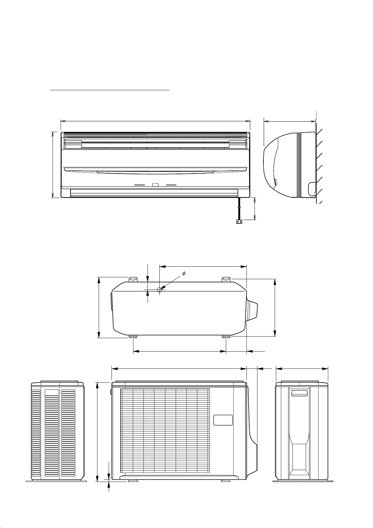
DIMENSIONS
Models : ASH14LSBCW / AOH14LFBC
ASH18LSBCW / AOH18LFBC
790
275
(unit : mm)
215
2,000
508
540
790
20
125
60
320
300
48
347
578
10
2004.10.19 2
Page 4
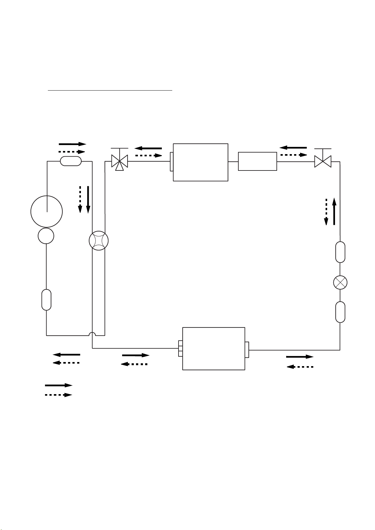
REFRIGERANT SYSTEM DIAGRAM
Models : ASH14LSBCW / AOH14LFBC
ASH18LSBCW / AOH18LFBC
Muffler
Compressor
3-Way
valve
4-Way valve
Heat exchanger
( INDOOR )
Sub-heat
exchanger
( INDOOR )
2-Way
valve
Strainer
Expansion valve
Sub-accumulator
Cooling
Heating
Heat exchanger
( OUTDOOR )
Strainer
2004.11.09 3
Page 5
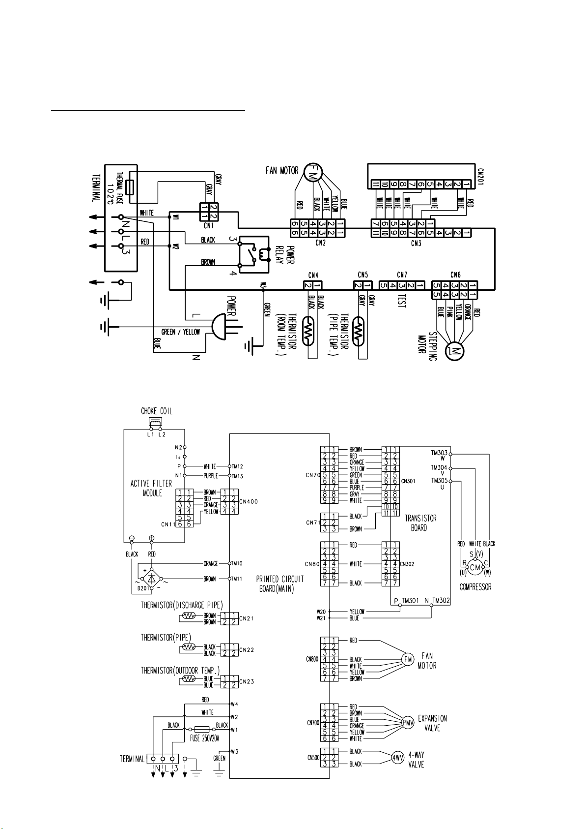
CIRCUIT DIAGRAM
Models : ASH14LSBCW / AOH14LFBC
AOH18LSBCW / AOH18LFBC
INDOOR UNIT
DISPLAY BOARD
CONTROL BOARD
OUTDOOR UNIT
2004.11.09 4
Page 6
ERROR CONTENTS
Self-diagnosis function table (Flashing LED Display)
Applicable model : ASH18LSBCW
* Detailed Trouble Display (secondary level) can be indicated by pressing Test Operation button.
Trouble Display (primary) Detailed Trouble Display (by Test Button)
Error Operation Timer Error Operation Timer
Serial signal Normal 1 sec
error blinking
Indoor unit 0.5sec 0.1sec
thermistor 2 times blinking
error
Serial reverse signal error
at operation start up
Signal reverse signal error
during operation
Serial forward signal error
at operation start up
Serial forward signal error
during operation
Indoor temperature
thermistor open
Pipe thermistor
open or short
0.1sec 0.5sec
blinking 2 times
0.1sec 0.5sec
blinking 3 times
0.1sec 0.5 sec
blinking 4 times
0.1sec 0.5sec
blinking 5 times
0.1sec 0.5sec
blinking 2 times
0.1sec 0.5sec
blinking 3 times
Detailed Error Item
When a signal is not read continuously for 10 secs
from power relay ON immediately after operation starts
>>Cooling 0 code transmission, automatic reset
When a signal is not read for 20 secs thereafter
>>Trouble display continues and power relay OFF
>>Permanent stop
When a signal is not read continuously for 10 secs
from power relay ON immediately after operation starts
>>Cooling 0 code transmission, automatic reset
When a signal is not read for 20 secs thereafter
>>Trouble display continues and power relay OFF
>>Permanent stop
Normal Serial Forward Signal can not be
received more than 10 secs
>>Releases when it becomes normal
Normal Serial Forward Signal can not be
received more than 10 secs ( after receiving
effective forward transfer signal)
>>Releases when it becomes normal
Thermistor detection value is open when
AC plug is inserted
IndoorIndoorIndoorIndoorIndoor OutdoorOutdoorOutdoor
>>Releases when value becomes normal
Thermistor detection value is open or short
when AC plug is inserted
Outdoor unit 0.5sec 0.1sec
thermistor 3 times blinking
error
Indoor unit 0.5sec 0.1sec
control error 4 times blinking
Discharge thermistor
open or short
Heat exchanger
thermistor open
Outdoor temperature
thermistor open or short
Forced automatic SW
welded
Main relay welded
Power interruption error
0.1sec 0.5sec
blinking 2 times
0.1sec 0.5sec
blinking 3 times
0.1sec 0.5sec
blinking 4 times
0.1sec 0.5sec
blinking 2 times
0.1sec 0.5sec
blinking 3 times
0.1sec 0.5sec
blinking 4 times
>>Releases when value becomes normal
Thermistor detection value is open or short
>>Outdoor unit stops
Releases when it becomes normal
Thermistor detection value is open
>>Outdoor unit stops
Releases when it becomes normal
Thermistor detection value is open or short
>>Outdoor unit stops
Releases when it becomes normal
Forced Auto SW is ON for more than
10 secs continuously
>>Error is indicated while it is ON
Normal Operation other than error indication
Serial Reverse Signal is received 1 min.
after Main relay becomes OFF
>>Error is indicated while serial reverse
signal is input on normal operation
Normal operation except error indication
50/60Hz is not detected after 4 secs of
power ON.
2004.10.29 5
>>Error is indicated and unit is stopped
Page 7

Trouble Display (primary) Detailed Trouble Display (by Test Button)
Error Operation Timer Error Operation Timer
Outdoor unit 0.5sec 0.1sec
control error 5 times blinking blinking 2 times
Indoor fan 0.5sec 0.1sec
motor error 6 times blinking blinking 2 times
Current trip
CT abnormal
Compressor rotation
error blinking 5 times
Outdoor unit fan drive
system abnormal
Abnormal lock
Abnormal rotation
0.1sec 0.5sec
0.1sec 0.5sec
blinking 3 times
0.1sec 0.5sec
0.1sec 0.5sec
blinking 6 times
0.1sec 0.5sec
0.1sec 0.5sec
blinking 3 3 times
Detailed Error Item
Current trip error is 2nd time within
start up
>>Permanent stop
Current detection value is 0A for more
than 1 sec when compressor is
operated at more than 56rps
>>Automatic release after 3 min. ST
Compressor location detection error (incl.
failed start up) for 3 times
>>Permanent stop
When outdoor fan abnormal fan motor
duty abnormal operated 5 times
Outdoor
>>Permanent stop
Detected rotation is 0 r.p.m. at start up or
at 56 secs after Fan mode is selected
IndoorIndoor OutdoorOutdoorOutdoorOutdoorOutdoorOutdoorOutdoor
>>Permanent stop
Detected rotation is 1/3 of target r.p.m. at
start up or at 56 secs after Fan mode is
selected
Refrigerant 0.5sec 0.1sec
cycle error 7 times blinking abnormal blinking 2 times
Optional 0.5sec 0.1sec
function 8 times blinking
error
Discharge temperature
Cooling high pressure
abnormal rise
Active filter voltage
abnormal (3rd time)
Active filter foltage
abnormal (1st time)
0.1sec 0.5sec
0.1sec 0.5sec
blinking 3 times
0.1sec 0.5sec
blinking 2 times
0.1sec 0.5sec
blinking 3
times
>>Permanent stop
Discharge Temperature protection
(Discharge temperature is 110degC)
operated 2 times
>>Permanent stop
High pressure rise protection (Outdoor
heat exchanger temperature is 65degC)
operated
>>Comp. OFF (releases after 3min.ST)
Error is indicated while 3 min.ST
Active Filter voltage error operated 3 times
>>Permanent stop
Active Filter Module error or open
detection protection operated
>>Automatic release after 3 min. ST
2004.10.29 6
Page 8

Models : ASH14LSBCW
ASH18LSBCW
INDOOR PCB CIRCUIT DIAGRAM
TERMINAL BOARD
N
BLUE
L
3
WHITE
RED
W2
W1
VA1
470V
R60 330K
<1/2W>
C1 0.1 <F>
W3
GREEN
C3
0.01
<F>
L1
1.3A
9.0mH
R2 2.2
<5W>
I C7
H I 2002 ( or GK30431 )
18
10
C2
0.01
<F>
UL1015
AWG22
GREEN
E
Jumper wire configurations
BROWN
3.15A
- 250V
R1 2.2
<5W>
BLACK
K1
D I 12D1
F1
FAN MOTOR
GREEN / YELLOW
E
D1
GS I B460L
R12
1.0K
<1/2W>
14
POWER SOURCE
230V
50Hz
F2
2.5A - 250V
C4
+
100/
420V
EN / UV
I C2
TNY266P
SSSSS
A
F M
VM
5
D
BP
32
7
R3 100K
<2W>
C5
0.01
D2 1NH42
PS2561-1
<L>
4
4
3
1
8
C6
0.1
<F>
1
4
5
2
3
CONTROLLER PCB ASSEMBLY ( MAIN PCB )
ASH14LSBCW : K02DR-0402HSE-C1
ASH18LSBCW : K02DR-0400HSE-C1
I C 1
uPD780024ASGB-X51-8ET-A
25
P10
AN I 0
17
P23
P24
18
24
P11
AN I 1
VDD0
10
20
VDD1
AVREF
26
27
AVDD
GND0
9
AGND
21
GND1
34
52
P47
19
P25
P01
36
I NTP1
46
P41
P40
45
P75
44
BUZ
14
P20
P03
38
15
P21
16
P22
P12
23
AN I 2
22
P13
AN I 3
39
P70
37
P02
I NTP2
X1
33
RESET
P00
I NTP0
X2
I C
P42
P35
P57
P56
P55
P54
P53
P52
P51
P50
P46
P45
P44
P43
P34
P36
XT1
XT2
P74
P73
P72
P71
32
X1
8.38MHz
31
28
C35
0.1
<F>
47
12
8
7
6
5
4
3
2
1
35
51
50
49
48
11
13
30
29
43
42
41
40
JP1
R46 1.0K
<1/8W>
5V
C28
0.1
<F>
C31
0.1
<F>
R42
100K
<1/8W>
6
5V
R36
10K
<1/8W>
5
R55 1.0K <1/8W>
R38 1.0K
<1/8W>
R40 1.0K
<1/8W>
5V
I C11
S80842
23
VDD
1
OUT
5V
R45
10K
<1/8W>
I C13-6
11
R30 330 <1/8W>
R29 330 <1/8W>
R28 330 <1/8W>
R27 330 <1/8W>
R37 47
C25
<1/8W>
1000P
<R>
12V
9
2
15
143
413
12
8
I C13-1
R44
10K
<1/8W>
NC
GND
SW1
5V
I C13-2
I C13-3
I C13-4
I C13-5
R39
10K
<1/8W>
(1%)
R41
49.9K
<1/8W>
(1%)
4
C26
100/
16V
5V
R56
10K
<1/8W>
1
I C12
S-93C46ADFJ
1
CS
2
SK
3
D I
TEST
7
NC
5V
CN4 2P-SAN
CN4-1 BLACK
CN4-2 BLACK
CN5-1 GRAY
CN5-2 GRAY
ROOM TEMPERA TURE THERMIST OR
PIPE TEMPERATURE THERMIST OR
CN5 2P-SCN
12V
INDICATOR PCB
K 1
CN201
5V
+
12V
16
JM19
JP3
C27
0.01
<B>
CN6
53325-0510
CN3
S07B-ZR-3.4
CN6-1 RED
CN6-2 ORANGE
CN6-3 YELLOW
CN6-4 PINK
CN6-5 BLUE
WHITE
WHITE
WHITE
WHITE
WHITE
5V
VCC
8
C36
4
DO
0.1
6
5
GND
<F>
RED
WHITE
JB20-11HG
CN201-1
CN201-2
CN201-3
CN201-4
CN201-5
CN201-6
CN201-7
CN201-8
CN201-9
CN201-10
CN201-11
M
K02CB-0300HSD-D0
5V
D208 SLR-325
D205 SLR-325 <GRN>
D204 SLR-325 <GRN>
D201 SLR-325 <RED>
C201
0.1 <F>
LOUVER
<ORG>
5V
C202
47/10V
5V
+
R201
47
<1/4W>
I C201
GP 1UM261RK
VCC
OUT
GND
I C3
C9
330/
25V
1
2
R5
2M
<1/4W>
15V
+
I C4
78M15
3
C10
0.1
<F>
O
G
2
JP7
1
I
R4 18K
<1/8W>
20V
+
C7
100/35V
D3
D1FL20U
T1
ETS19AB1P8AG
6
10
D4
D2FL20U
4
2
5
1
7
C11 0.01 <F>
THERMAL FUSE
13.5V
C12
+
330/
25V
I C5
TL431 I LP
CN1
102
GRAY
C
A
R7
1.0K
<1/8W>
GRAY
12V
REF
C14
0.01
<B>
C15
330/
25V
D5
D1F60
I C6
7805
I
+
R8 47K
<1/8W>
O
G
C16
0.1
<F>
R9
34K
<1/8W>
(1%)
R10
8.25K
<1/8W>
(1%)
R53,R54
10K <1/8W>
5V
C18
10/
25V
C17
+
330/
25V
5V
C19
+
0.1
<F>
5V
5V
C20
0.01
<B>
C21
0.01
<B>
7
C22
Q4
DTC124EUA
C23
1000P
<R>
TEST
RED
BLACK
WHITE
YELLOW
BLUE
BZ
PKM13EPY-4000-TF01
CN7
BS5P-SHF-1AA
CN7-1
CN7-2
CN7-3
CN7-4
CN7-5
CN2-6
CN2-4
CN2-3
CN2-2
CN2-1
12V
TIMER SHORT
CLOCK
DATA-OUT
DATA-I N
CN2
53426-9920
Q2
DTC124EUA
R43 10K
<1/8W>
B Z
5V
CUSTOM CODE SWITCHING
JM1
JM2
AUTO RESTART
VM
15V
C24
A
100/
16V
R23 6.8K <1/4W>
R26 820
<1/4W>
(1%)
+
A
A
Q1
DTC124EUA
R49 - R52, R47,R48
10K <1/8W> x 6
15VR25 1.0K
<1/4W>
(1%)
15V
15V
R22
4.7K
<1/8W>
R13
10K
<1/8W>
I C10
PS2561-1
<L>
4
3
I C9
PS2561-1
<L>
1
2
R14 1.0K
<1/8W>
R15 1.0K <1/8W>
I C13-7
10
5V
R24 330
1
<1/8W>
2
5V
R21
10K
<1/8W>
4
3
R20 1.0K
<1/8W>
Switch Function ON/Linked OFF/Open
JM1 Custom code A B
JM2 Auto restart enable disable
2004.12.02 7
Page 9

Models : AOH14LFBC
AOH18LFBC
POWER SOURCE
230V
50Hz
1
2
3
TERMINAL BOARD
HPT3031-3-L3
FAN MOTOR
EXPANSION VALVE
DISCHARGE TEMPERATURE THERMIST OR
HEAT EXCHANGER THERMISTOR
OUTDOOR TEMPERATURE THERMIST OR
POWER
POWER
UL1015 AWG14 BLACK
SERIAL
F M
4-WA Y VALVE
M
F201
20A - 250V
HP-F2018-3
UL1015 AWG20 RED
EARTH
RED
BLACK
WHITE
YELLOW
BROWN
BLACK
BLACK
RED
BROWN
BLUE
ORANGE
YELLOW
WHITE
BROWN
BROWN
BLACK
BLACK
BLUE
BLUE
UL1015
AWG14
BLACK
UL1015
AWG14
WHITE
UL1015
AWG16
GREEN
BW1
(A-1)
BW2
(B-1)
BW4
(D-1)
BW3
(C-1)
CN800
BH5 (7 - 2.3) B-XASK-1-A
(H-1)
1
2
3
4
5
6
7
CN500
B2P3-VH-B-C
(F-7)
1
2
3
1
2
3
4
5
6
CN700
BH6B-XARK-1-A
(I-1)
CN21
1
BH2B-XH-AM
2
(K-1)
CN22
1
BH2B-XH-AM
2
(K-1)
CN23
1
BH2B-XAEK-1-A
2
(K-1)
YELLOW
RED
(B-7)
(A-7)
TM11
TM10
W11
UL1015
AWG12
BROWN
W10
UL1015
AWG12
ORANGE
D201
D25VB60
OUTDOOR PCB CIRCUIT DIAGRAM
INVERTER ASSEMBLY
AOH14LFBC : EZ-0043HUE
AOH18LFBC : EZ-0044HUE
CHOKE COIL
W201
UL1015
AWG12
RED
+
-
W202
UL1015
AWG12
BLACK
CONTROLLER PCB ASSEMBLY
AOH14LFBC : EZ-0043HUE
AOH18LFBC : EZ-0044HUE
L1 L2
+
I C404
SACT32010A
-
A C T P M
CN11
P
W13
N1
N2
I O
1
2
3
4
5
6
UL1007 AWG24 BROWN
UL1007 AWG24 RED
UL1007 AWG24 ORANGE
UL1007 AWG24 YELLOW
UL1015 AWG14 WHITEW12
UL1015 AWG14 PURPLE
W401
TM12 (A-9)
TM13 (B-9)
CN80
BH3 (7.5) B-XAKK-1-A
1
(F-16)
2
3
4
CN400
BH4B-XASK-1-A
(E-11)
CN70
BH9B-XAKK-1-A
(I-16)
CN71
BH3B-XASK-1-A
(H-16)
W20
B
(A-15)
B W21
(B-15)
1
2
3
4
5
6
7
1
2
3
4
5
6
7
8
9
1
2
3
UL1015 AWG14
YELLOW
UL1015 AWG14
BLUE
RED
WHITE
BLACK
W302
UL1007
AWG24
BROWN
RED
ORANGE
YELLOW
GREEN
BLUE
PURPLE
GRAY
WHITE
BLACK
BROWN
W301
UL1007
AWG24
(C-9)
TM301
TM302
(C-9)
CN302
BH3 (6.0) B-PASK-1
(F-12)
1
2
3
TRANSISTOR PCB ASSEMBLY
4
5
K04DS-0400HUE-TR0
6
7
CN301
BH11B-PASK-1
(F-4)
1
2
3
4
5
6
7
8
9
10
11
(C-9)
(C-9)
(C-9)
TM305
TM304
TM303
RED
U
WHT
V
BLK
W
EMI FILTER 2
ZCAT2132-1130
COMPRESSOR
C M
PEX-125F
2004.12.03 8
Page 10

Models : AOH14LFBC
AOH18LFBC
CONTROLLER PCB ASSEMBLY
AOH14LFBC : K04AJ-0400HUE-C1
AOH18LFBC : K04AJ-0401HUE-C1
W1
L
VA1
W2
N
W3
EARTH
W4
SERIAL
VA2
TNR10V471
K370
DC-3
CN800 BH5 (7-2.3) B
-XASK-1-A
FAN MOTOR
CN700 BH6B-XARK-1-A
ELECTRICAL
EXPANSION VALVE
CN21 BH2B-XH-AM YELLOW
DISCHARGE PIPE
TEMP . TH.
CN22 BH2B-XH-AM RED
HEAT EXCHANGER
TH.
CN23 BH2B-XAEK-1-A
OUTDOOR
TEMP . TH.
1
2
3
4
5
6
7
12V
1
2
3
4
5
6
2
1
2
1
2
1
8
330V-3
15V
C802
0.1 <F>
L800 BL02Rn1
R804 1.0K <1/10W>
L70
BL02Rn1
C53
0.1
<F>
C100
1.0
<LE>
SA100
RA-302M-V7-F
D13
AC+
7
240V
5V, 12V, 15V Line
18V Line
A
Power Line
D
C800
+
100/
16V
<PJ>
5V
R63 6.65K
<1/10W>
(1%)
AC-
240V
R801 1.0K
<1/4W>
R802
560
<1/4W>
R803 10K
<1/10W>
R65
4.75K
<1/10W>
L1
UL1015
AWG14 x 2
H Y I C 1
GK-30434
101418
6
15V
5V
2
O1
7
O2
9
O3
O4
16
4
GND1
5
GND2
12
GND3
GND4
13
I C700
TD62064AP
R67 38.3K
<1/10W>
(1%)
C103
1.0
<LE>
Q801
DTC143EUA
1
3
C801
0.01
<B>
I 1
I 2
I 3
I 4
COM1
COM2
NC1
NC2
L2
SC-12-1000JH
5V
2
3
5V
1
D600
DAN217U
3
6
11
14
1
8
10
15
2
1
4
3
5
5
2
Q800
DTC143EUA
R700 1.5K <1/10W>
R701 1.5K <1/10W>
R702 1.5K <1/10W>
12V
R703 1.5K <1/10W>
R62 10K
<1/10W>
R64 10K
<1/10W>
R66 10K
<1/10W>
C68
C106
1.0
<LE>
C66
0.1
<F>
1234
AC+
240V
C104
0.01 <YE>
C105
0.01 <YE>
1234
R51
4.7K
<1/10W>
C67
0.1
<F>
L3
N200500K107C-01
C107
1.0 <LE>
AC
240V
CT1
CT-1B
5V
R50
10K
<1/10W>
C65
0.1
<F>
-
R53 1.0K
<1/10W>
R100
ZPR0RCH400
C108
3.3
<LE>
324
12V
4
5
D60
DAN217U
3
1
R60 2.2K
<1/10W>
(1%)
R52 1.0K <1/10W>
C51
0.1
<F>
AC+
240V
1
2
3
4
K500
G5NB-1A
JM107
R107
1.0K
<1/10W>
JM106
R106
1.0K
JM105
<1/10W>
R105
1.0K
JM104
<1/10W>
R104
1.0K
JM103
<1/10W>
R103
1.0K
JM102
<1/10W>
R102
1.0K
JM101
<1/10W>
R101
1.0K
<1/10W>
MODEL CHANGE
K101
DW1201
1
-0 (M)
5V
C52
0.1
<F>
JM501
12V
4-WA Y V ALVE
12V
D28
SLR-332VR
5V
C60
220/
16V
<PJ>
AOY18AOY14
JM107
JM106
JM105
JM104
JM103
JM102
JM101
TEST
JM100
TM10
TM11
R69 1.0K
<1/10W>
+
JM502
CN500
B2P3-VH-B-C
R43 2.2K
<1/10W>
R108 10K
<1/10W>
JM60
R61
4.75K
<1/10W>
(1%)
C55
0.1
<F>
5V
R18
10K
<1/10W>
R68 22K
<1/10W>
C64
0.1
<F>
1
3
ULN2003ANS
15
11
12
10
13
14
C54
0.1
<F>
D402
RD3.3ES
<B2>
C17
0.1
<F>
116
2
6
5
7
4
3
15V
R403
2.7K
<1/10W>
CR500
0.2uF + 120
I C3-1
I C3-2
I C3-6
I C3-5
I C3-7
I C3-4
I C3-3
R72 1.0K
<1/10W>
C409
+
10/
25V
<PS>
DC-1
330V
R400
180K
<RN-1/2W>
R401
180K
<RN-1/2W>
R402
6.65K
<1/10W>
TM12
TM13
R404 1.0K
<1/10W>
JM500
AC-
240V
JM503
X1
8.00MHz
R73 100K
<1/10W>
2
1
VDD
OUTNCGND
I C5
S80842
C411
0.01
<F>
MB90462PFM-G
-156-BND-E1
13
2
5V
3
4
D300
DAN217U
5V
R405
10K
<1/10W>
C402
0.01
<F>
Q403
DTA143EUA
3
1
A
R411
22K
<1/10W>
R80 27K <1/10W>
C202
660
450V
2
C415
1000P
<B>
R303 1.0K
<1/10W>
C80
100P
<CH>
C201
++
660
450V
I C400-1
2
-
1
3
+
6
-
7
5
+
I C400-2
Q401
DTC124EUA
2
5V
17
56
VCC
P63
16
P62
11
AVCC
25
P00
2
P46
P01
P12
35
26
P17
3
40
P50
59
36
P13
P37
P14
58
37
P36
60
38
P15
P40
21
39
P16
MD2
AVR
34
12
P11
P24
47
45
P26
27
46
P25
P02
28
50
P30
P03
P31
29
51
P04
P32
52
30
P05
31
P06
53
P33
32
54
P34
P07
33
55
P35
P10
14
P60
57
C
P61
P20
41
15
42
18
P21
MD0
20
43
P22
MD1
P44
P23
44
64
10
63
P43
P57
62
P42
9
P56
61
P41
8
P55
7
1
P45
P54
19
RSTX
5
P52
6
48
P27
P53
AGND
13
4
P51
GND
X0
22
24
GND
23
49
X1
I C 1
18V
5V
21
3
C300
0.1
<F>
1
18V
3
5V
R95
1.0K
<1/10W>
R56 10K
<1/10W>
DC-3
330V-3
R300 195K
<RN-1/2W>
R301 195K
<RN-1/2W>
R302
3.83K
<1/10W>
(1%)
C400
0.1
<F>
A
1
2
3
4
A
Q80
2SC2412K
<BQ>
C50
0.1
<F>
5V
R606
1.0K
<1/10W>
CN400
BH4B-XASK
-1-A
C413
536
<1/10W>
(1%)
3
2
C18
0.1
<F>
R57 10K
D
Q1
2SC4236
R6 2.4
<1/2W>
ACTPC
CONTROL
5V
15V
R96 4.7K
<1/10W>
1
5V
C19
+
4.7/
50V
<PS>
I C600
BR93L46RF-WE2
5V
10K <1/10W> x 3
R42R59
<1/10W>
5V
R607
1.0K
<1/10W>
2
3
R81
22K
<1/10W>
I C80-1
I C80-2
1
CS
2
SK
3
D I
6
NC
R58
R605
10K
<1/10W>
R202
220K
<2W>
DC-3
330V-3
1
1
-
+
7
-
+
R600
10K
<1/10W>
VCC
DO
NC
GND
R1
220K
<2W>
D10
D1
D1FL
20U
2
3
6
5
8
4
7
5
DC-1
330V
R3 100
<1W>
RD5.6ES
<B2>
C85
4.7/
50V
<PS>
5V
5V
F1
15A - 250V
R2 1.0K
<RS-3W>
D2
D1FL20U
C3
100/16V
R4
<PJ>
330
<1/4W>
D81 DAN217U
+
C86
C84
470P
0.1
<B>
<F>
C600
0.1
<F>
R603
10K
<1/10W>
C1
220P
<B>
C2 0.047
<ECQB>
D
15V
DC-2
330V-2
+
C87
330P
<B>
5V
R609
10K
<1/10W>
PFC5000-0502
FH1 FH2
BET 3.15A - 250V
T1
JPZ-200
16
15
13
12
10
9
D1FL20U
C8
220/
35V
<PJ>
L80
D82
DAN217U
R86 8.66K
<1/10W>
(1%)
F4
1
2
3
6
7
8
15VD7
+
DC-2
330V-2
R83 195K
<RN-1/2W>
R84
195K
<RN
-1/2W>
5V
R604
10K
<1/10W>
DC-3
330V-3
D3
D2FL20U
D4
D1FL20U
R5 10K
<1/10W>
D5
D1FL20U
R93 5.76K
<1/10W>
(1%)
R94 143
<1/10W>
(1%)
C406
220/50V
<PJ>
R88 195K
<RN-1/2W>
R90 195K
<RN-1/2W>
R92 195K
<RN-1/2W>
R40 1.0K
<1/10W>
C33
0.01
<F>
C207
0.1
<HCP>
C5
+
220/
16V
<PJ>
I C407
uPC24M18
13
I
+
5V
R33
4.7K
<1/10W>
G
2
+
O
D403
ZP1027
W20
W21
I C7
TA7805
1
G
C4
470/
25V
<PJ>
18V
+
R87 195K
<RN-1/2W>
R89 195K
<RN-1/2W>
R91 195K
<RN-1/2W>
O
C34
0.01
<F>
32I
C418
10/35V
<PS>
A
C71
0.1
<F>
12V
5V
C6
+
100/16V
<PS>
15V
C70
0.1
<F>
CN80
BH3 (7.5B)
-XAKK-1-A
1
2
3
POSITION
4
DETECTOR
5
6
7
CN71
BH3B-XASK
1
I PM
2
POWER
3
SUPPLY
5V
CN70
BH9B-XAKK
-1-A
1
2
3
4
I PM
5
CONTROL
6
7
8
9
2004.12.03 9
Page 11

Models : AOH14LFBC
AOH18LFBC
TRANSISTOR PCB ASSEMBLY
K02DS-0400HUE-TR0
5V
GND
FO
WN
VN
UN
WP
VP
UP
15V
GND
CN301
BH11B-PASK-1
15V
5V 15V
C300
0.1
<F>
1
2
3
4
5
6
7
8
9
10
11
R360 39
<1/2W>
C301
0.1
<F>
15V5V
D301 U1JU44
D302 U1JU44
D303 U1JU44
R316 1.0K <1/10W>
R317 1.0K <1/10W>
R318 1.0K <1/10W>
R319 1.0K <1/10W>
R320 1.0K <1/10W>
5V
R321 1.0K <1/10W>
R303
4.7K
<1/10W>
C311
1000P
<B>
C312
1000P
<B>
C321
0.1
<F>
C313
1000P
<B>
R362 330K
<1/10W>
C314
1000P
<B>
C303
47/
35V
<PJ>
C315
1000P
<B>
C322
0.1
<F>
+
R363 330K
<1/10W>
C316
1000P
<B>
C323
0.1
<F>
C304
47/
35V
<PJ>
15V 15V
C324
0.1
<F>
+
R361 330K
<1/10W>
C325
0.1
<F>
C326
0.1
<F>
C305
47/
35V
<PJ>
15V
+
I C301
PS21865
1
UP
VP I
2
3
VUFB
4
VUFS
5
VP
6
VP I
7
VVFB
8
VVFS
WP
9
10
VP I
11
VPC
VWFB
12
VWFS
13
TM301
TM302
TM303
TM304
TM305
VN I
VNC
C I N
CFO
FO
UN
VN
WN
P
U
V
W
N
C327
0.022
<F>
P
N
W
V
C328
R301 0.02
<1/10W>
2200P
U
<B>
R302 1.0K
<1/10W>
15V
D307
C332
ZP1027
0.1
<F>
14
15
16
17
18
19
20
21
22
23
24
25
26
C207
0.1
<F>
1
2
3
4
5
6
7
CN302
BH3 (6.0) B-PASK-1
POSITION DETECTOR
2004.11.02 10
Page 12

Models : ASH14LSBCW
ASH18LSBCW
DISASSEMBLY ILLUSTRATION
5
51
6
5
4
3
1
1
2004.12.01 11
2
7
Page 13

Models : ASH14LSBCW
ASH18LSBCW
236
26
188
48
28
32
52
31
24
29
27
39
40
37
46
20
43
30
61-2
23
21
61-1
36
32
38
42
33
2004.12.01 12
Page 14

Models : AOH14LFBC
AOH18LFBC
9
14
37
8
13
11
19
32
10
29
25
30
26
33
35
24
23
20
38
15
5
22
12
21
39
27
1
31
28
2
18
16
34
17
2004.10.29 13
3
6
7
4
36
Page 15

INDOOR UNIT
PARTS LIST
Ref.
No.
1 Air Filter 9309997011
Filter (Electric) 9312153015
2
3 Filter (ION) 9311925033
4
Holder (Filter) 93066020179306602017
Clamper (Grille) 9306755010
5
6 Front Panel Total Assy 9313130107
Intake Grille Assy 9313131067
7
20 Gear-A 9309994003
21 Casing Assy 9312112081
23 Cover (Casing)-B 9311916017
24 Crossflow Fan Assy 9307836015
26 Clamp (Motor) 9310102008
27 Shaft Holder-C Assy 9306628017
28 Drain Hose Assy 9310357019
29 Drain Cap Assy 9304150008
30
Wire Clamper 9311946014
Box (Switch) 9309996014
31
32 Cover (Switch) 9311863014
33 Evaporator Total Assy 9313099015
Joint Pipe Assy-E 9311497011
36
Description
ASH14LSBCW ASH18LSBCW
9309997011
9312153015
9311925033
9306755010
9313130107
9313131067
9309994003
9312112081
9311916017
9307836015
9310102008
9306628017
9310357019
9304150008
9311946014
9309996014
9311863014
9313099015
9311497011
Part No.
Ord.
Q'ty
37 Insulation (Pipe)-E 9304607007
38
Holder (Evaporator)-L 9309982017
39 Holder (Evaporator)-R 9309983014
40 Water Seal 9310721001
42 Air Seal 9310611005
43
Terminal 9701955077
46
Step Motor 9900139025
48 Fan Motor Assy 9601351016
51
Remote Control Unit 9313144012
52
Bracket Panel 9310001004
61-1 Flow Control Panel-U 9309991033
61-2
Flow Control Panel-Z 9309992030
188
236 Controller PCB Assy 9705656017
Power Cord 9900001025
--- Pipe Temperature Thermistor 9702039042
Room Temperature Thermistor 9700801108
---
--- Indicator PCB Assy 9705039032
When you order parts, please make a photocopy of this page
and fill the number of the parts in the "Order" column.
9304607007
9309982017
9309983014
9310721001
9310611005
9701955077
9900139025
9601351016
9313144012
9310001004
9309991033
9309992030
9900001025
9705656048
(K02DR-0402HSE-C1) (K02DR-0400HSE-C1)
9702039042
9700801108
9705039032
2004.12.02
14
Page 16

OUTDOOR UNIT
Ref.
No.
1 Top Panel 9308883025
2 Top Panel Seal 9309228016
3 Cabinet 9308878021
4 Blow Down Grille 9308884015
5 Cabinet-R 9308879028
6 Fan Ring 9308885012
7 Grip 9308880017
8 Switch Cover 9308882028
9 Protective Net 9312026012
10 4-Way Valve Assy 9313755027
11 Expansion Valve Assy 9311641018
12 Dryer 9312056002
13 Condenser 9311381037
14 Thermistor Spring-A 313728262708
15 Thermistor Spring-A 9300089012
16 Propeller Fan 9309909014
17 Nut 9304902003
18 Motor Bracket 9308872012
19 Separator 9312032013
20 Base Assy, Painted 9308869081
Description
AOH14LFBC AOH18LFBC
9308883025
9309228016
9308878021
9308884015
9308879028
9308885012
9308880017
9308882028
9312026012
9313755027
9311641018
9312056002
9311381037
313728262708
9300089012
9309909014
9304902003
9308872012
9312032013
9308869081
Part No.
Ord.
Q'ty
21 3-Way Valve Assy 9313554019
22 2-Way Valve Assy 9313064013
24 Cord Clamp 9307271014
25 Terminal 9306489038
26 Inverter PCB Assy 9705622029
27 TR PCB Assy 9705628014
28 ACTPM 9703457012
29 Fuse 0600036027
31 Transformer 9705071018
32 Expansion Valve Coil 9900057039
33 Choke Coil 9703458019
34 Fan Motor 9601815013
35 Compressor Assy 9313764012
36 Emblem 9312635016
37 Heat Exchanger Thermistor 9704220028
38
Discharge Temperature Thermistor
39 Solenoid Coil 9970033018
--- IPM 9705441026
--- ACTPM 97034570129703457012
9313554019
9313064013
9307271014
9306489038
9705622012
9705628014
9703457012
0600036027
9705071018
9900057039
9703458019
9601815013
9313764012
9312635016
9704220028
9704219091
9970033018
9705441026
When you order parts, please make a photocopy of this page
and fill the number of the parts in the "Order" column.
9704219091
2004.12.01
15
Page 17

STANDARD ACCESSORIES
Part No.
Name and Shape
Wall hook bracket
Remote control
unit
Remote control
unit holder
ASH14LSBCW, ASH18LSBCW
9312752010
9308846099
9305642014
Battery (penlight)
Cloth tape
Tapping screw (big)
( 4 x 25)
Tapping screw (small)
( 3 x 12)
Air cleaning filter
Air cleaning filter
frame
0600185534
9310519004
0700076046
0700019036
9312153015
9311925033
9306602017
2004.12.01
16
Page 18

0409G2664
 Loading...