

Page 1

EC DECLARATION OF CONFORMITY
CE-KONFORMITÄTSERKLÄRUNG
DECLARATION DE CONFORMITE-CE
CE DECLARACIÓN DE CONFORMIDAD
DICHIARAZIONE DI CONFORMITÀ CE
∆ΗΛΩΣΗ ΕΓΚΡΙΣΗΣ ΚΑΤΑΛΛΗΛΟΤΗΤΑΣ
CE VERKLARING VAN OVEREENSTEMMING
EG-FÖRSÄKRAN OM ÖVERENSSTÄMMELSE
DECLARAÇÃO DE CONFORMIDADE DA
COMUNIDADE EUROPEIA (CE)
FUJITSU GENERAL (EURO) GmbH
Werftstraße 20, D-40549 Düsseldorf, F. R. Germany
declares under its sole responsibility that the air conditioning models
erklärt hiermit, daß die nachfolgend bezeichneten Raumklimageräte
déclare sous sa seule responsabilité que les modèles de climatiseur ci-dessous
declara bajo su exclusiva responsabilidad que los modelos de acondicionadores de aire
dichiara sotto la sua unica responsabilità che i condizionatori d’aria modelli
δηλώνει, οτι µε δική τησ υπευθυντητα τα µοντέλα των κλιµατιστικών
verklaart onder eigen verantwoordelijkheid dat de airconditioning-modellen
intygar på eget ansvar att luftkonditioneringsmodellerna
declara sob sua responsabilidade que os modelos de ar condicionado
ASY13PSCCW/AOY13PNCC ASH13PSCCW/AOH13PNCC
to which this declaration relates is in conformity with the following standards:
worauf sich diese Konformitätserklärung bezieht, folgenden Richtlinien entspricht:
auxquels la présente déclaration s’applique, sont conformes aux normes suivantes:
como esta declaración especifica, cumplen con las siguientes normas:
ai quali si riferisce la presente dichiarazione sono conformi ai seguenti standars:
εισ τα οποία η παρούσα δήλωση αναφέρεται, είναι προσαρµοσµένα σύµφωνα µε τα παρακάτω πρτυπα:
waarop deze verklaring van toepassing is, in conformiteit zijn met de volgende normen:
till vilka denna deklaration är relaterade, är i överensstämmelse med följande standarder:
indicados na declaração estão em conformidade com as normas seguintes:
By conformance with the standards, the referenced products follows the provisions of the directives listed
below:
In Übereinstimmung mit den Standards, erfüllen die obengenannten Produkte den Verordnungen der unten
aufgeführten EG-Richtlinien:
Par leur conformité aux normes précitées, les appareils de ce type répondent aux exigences des directives
suivantes:
De acuerdo con estas normas, los productos referenciados cumplen lo estipulado por las directivas listadas a
continuación:
Od altri documenti normativi conformi alle disposizioni delle direttive sotto elencate:
Τα αναφερµενα µοντέλα, σύµφωνα µε τουσ κανονισµούσ, ακολουθούν τισ απαιτήσεισ ασφαλείασ των κάτωθι
άρθρων:
Overeenkomstig de normen, voldoen de betreffende produkten aan de bepalingen van de hieronder vermelde
richtlijnen:
Genom överensstämmelse med dessa standarder, uppfyller de berörda produkterna föreskrifterna i de
direktiv som anges här nedan:
Os seguintes produtos referenciados na lista abaixo, estão em conformidade com as normas:
a. EC Council Directive 73/23/EEC b. EC Council Directive 89/336/EEC
Place of Issue : F.R. Germany Title of Authority : General Manager
Date of Issue : 27 DECEMBER 2001 Declaration Reference : FUJITSU GENERAL (EURO) GmbH
Werftstraße 20, D-40549
Düsseldorf, F. R. Germany
a. EN 60 335-1
b. EN 60 335-2-40
c. EN 55 014-1
d. EN 55 014-2
e. EN 61 000-3-2
f. EN 61 000-3-3
Authorized by : Signature:
JUNJI YANAGIMOTO
FUJITSU GENERAL LIMITED
EnglishDeutsch
Français
Español
ItalianoEλληvIkά
OPERATING MANUAL
BEDIENUNGSANLEITUNG
MODE D’EMPLOI
MANUAL DE FUNCIONAMIENTO
MANUALE DI ISTRUZIONI
ΕΓΧΕΙΡΙ∆ΙΟ ΛΕΙΤΟΥΡΓΙΑΣ
MANUAL DE INSTRUÇÕES
РУКОВОДСТВО ПО ЭКСПЛУАТАЦИИ
P/N9311470021-03
Indoor Unit
ASH13PSCCW
Outdoor Unit
AOH13PNCC
HEAT & COOL MODEL
(REVERSE CYCLE)
ROOM AIR CONDITIONER
WALL MOUNTED TYPE
Русский
Português
KEEP THIS OPERATION MANUAL
FOR FUTURE REFERENCE
Page 2

Fig. 4
Fig. 1
Fig. 2
Fig. 3
]
^
a
b
c
d
e
f
g
QUIET
U
X
T
[
Y
S
R
Q
V
Z
W
O
P
OPEN
TEST
RUN
\
Fig. 7
CONTENTS
SAFETY PRECAUTIONS..................................... En-1
FEATURES AND FUNCTIONS ........................... En-2
NAME OF PARTS ................................................ En-3
INDOOR TEMPERATURE DISPLAY ................... En-3
PREPARATION .................................................... En-4
OPERATION ........................................................ En-5
AIR CLEANING OPERATION .............................. En-7
HI-POWER OPERATION ..................................... En-8
TIMER OPERATION ............................................ En-9
SLEEP TIMER OPERATION .............................. En-10
ADJUSTING THE DIRECTION OF AIR
CIRCULATION ................................................... En-11
SWING OPERATION......................................... En-12
MANUAL AUTO OPERATION .......................... En-12
CLEANING AND CARE ..................................... En-13
CLEANING THE PLASMA AIR CLEANING
FILTER ................................................................ En-14
CLEANING THE LIGHT-REGENERATED
DEODORIZING FILTER ..................................... En-16
TROUBLESHOOTING ....................................... En-17
OPERATING TIPS.............................................. En-20
SAFETY PRECAUTIONS
● Do not attempt to install this air conditioner by yourself.
● This unit contains no user-serviceable parts. Always consult authorized service per-
sonnel for repairs.
● When moving, consult authorized service personnel for disconnection and installation of the unit.
● Do not become excessively chilled by staying for lengthy periods in the direct cooling
airflow.
● Do not insert fingers or objects into the outlet port or intake grilles.
● Do not start and stop air conditioner operation by disconnecting the power supply
cord and so on.
● Take care not to damage the power supply cord.
● In the event of a malfunction (burning smell, etc.), immediately stop operation, dis-
connect the power supply plug, and
consult authorized service personnel.
● If the power supply cord of this appliance is damaged, it should only be replaced by
the authorized service personal, since special purpose tools and specified cord are
required.
● Provide occasional ventilation during use.
● Do not direct air flow at fireplaces or heating apparatus.
● Do not climb on, or place objects on, the air conditioner.
● Do not hang objects from the indoor unit.
● Do not set flower vases or water containers on top of air conditioners.
● Do not expose the air conditioner directly to water.
● Do not operate the air conditioner with wet hands.
● Do not pull power supply cord.
● Turn off power source when not using the unit for extended periods.
● Check the condition of the installation stand for damage.
● Do not place animals or plants in the direct path of the air flow.
● Do not drink the water drained from the air conditioner.
● Do not use in applications involving the storage of foods, plants or animals, precision
equipment, or art works.
● Connection valves become hot during Heating; handle with care.
● Do not apply any heavy pressure to radiator fins.
● Operate only with air filters installed.
● Do not block or cover the intake grille and outlet port.
● Ensure that any electronic equipment is at least one metre away from either the in-
door or outdoor units.
● Avoid installing the air conditioner near a fireplace or other heating apparatus.
● When installing the indoor and outdoor unit, take precautions to prevent access to
infants.
● Do not use inflammable gases near the air conditioner.
DANGER!
CAUTION!
En-1
ROOM
TEMP.
CLEAN
AIR
POLLUTED
AIR
OPERATION
TIMER
SWING
AIR CLEAN INDICATOR
HI-POWER
1
2
34
5
6
7
8
9
0
A
B
C
D
E
F
H
I
JG
PRESSIONE MASSIMA
ASPIRAZIONE ................................................................ 800 kPa
EMISSIONE ................................................................. 2.700 kPa
REFRIGERANTE ............................................................R22 1.050 g
DIMENSIONI E PESO
APPARECCHIO INTERNO
Altezza × Larghezza × Profondità ............. 290/815/215 mm
Peso ................................................................. 11,5 kg (netti)
APPARECCHIO ESTERNO
Altezza × Larghezza × Profondità ............. 535/695/250 mm
Peso .................................................................... 35 kg (netti)
ΜΕΓΙΣΤΗ ΠΙΕΣΗ
ΑΝΑΡΡΟΦΗΣΗ ............................................................... 800 kPa
ΕΚΤΟΝΩΣΗ ................................................................. 2.700 kPa
ΨΥΚΤΙΚΟ .......................................................................R22 1.050 g
∆ΙΑΣΤΑΣΕΙΣ ΚΑΙ ΒΑΡΟΣ
ΕΣΩΤΕΡΙΚΗ ΜΟΝΑ∆Α
ΥΨΟΣ/ΠΛΑΤΟΣ/ΒΑΘΟΣ ............................. 290/815/215 mm
ΒΑΡΟΣ ...................................................... 11,5 kg (ΚΑΘΑΡΟ)
ΕΞΩΤΕΡΙΚΗ ΜΟΝΑ∆Α
ΥΨΟΣ/ΠΛΑΤΟΣ/ΒΑΘΟΣ ............................. 535/695/250 mm
ΒΑΡΟΣ ......................................................... 35 kg (ΚΑΘΑΡΟ)
DATI TECNICI
ALIMENTAZIONE................................................. 220-230 V~50 Hz
RAFFREDDAMENTO
CAPACITÀ ........... 3,70 kW (minimo 1,03 ~ massimo 4,00 kW)
CONSUMO ......... 1,51 kW (minimo 0,35 ~ massimo 1,82 kW)
CORRENTE .................................................................. 6,9-6,6 A
RAPPORTO ENERGETICO DI EFFICIENZA ........................ 2,45
RISCALDAMENTO
CAPACITÀ ........... 5,00 kW (minimo 0,80 ~ massimo 6,10 kW)
CONSUMO ......... 1,83 kW (minimo 0,33 ~ massimo 2,28 kW)
CORRENTE .................................... 8,4-8,0 A (massimo 10,0 A)
RAPPORTO ENERGETICO DI EFFICIENZA ........................ 2,73
XAPAKTHPITIKAΣTIKA
ΤΡΟΦΟ∆ΟΣΙΑ ...................................................... 220-230 V~50 Hz
ΨΥΞΗ
∆ΥΝΑΤΟΤΗΤΑ ...... 3,70 kW (Ελάχιστο 1,03 ~Μέγιστο 4,00 kW)
ΙΣΧΥΣ ΕΙΣΟ∆ΟΥ ..1,51 kW (Ελάχιστο 0,35 ~Μέγιστο 1,82 kW)
ΡΕΥΜΑ ......................................................................... 6,9-6,6 A
ΣΥΝΤΕΛΕΣΤΗΣ ΑΠΟ∆ΟΣΕΩΣ ΕΝΕΡΓΕΙΑΣ ........................ 2,45
ΘΕΡΜΑΝΣΗ
∆ΥΝΑΤΟΤΗΤΑ ...... 5,00 kW (Ελάχιστο 0,80 ~Μέγιστο 6,10 kW)
ΙΣΧΥΣ ΕΙΣΟ∆ΟΥ ..1,83 kW (Ελάχιστο 0,33 ~Μέγιστο 2,28 kW)
ΡΕΥΜΑ ............................................ 8,4-8,0 A (Μέγιστο 10,0 A)
ΣΥΝΤΕΛΕΣΤΗΣ ΑΠΟ∆ΟΣΕΩΣ ΕΝΕΡΓΕΙΑΣ ........................ 2,73
MODEL
INDOOR UNIT APPARECCHIO INTERNO
MODELL
INNENGERÄT ΕΣΩΤΕΡΙΚΗ ΜΟΝΑ∆Α
ASH13PSCCW
MODÈLE
UNITÉ INTÉRIEURE UNIDADE INTERIOR
MODELO
UNIDAD INTERIOR ВНУТРЕННИЙ ПРИБОР
MODELLO
OUTDOOR UNIT APPARECCHIO ESTERNO
ΜΟΝΤΕΛΟ
AUSSENGERÄT ΕΞΩΤΕΡΙΚΗ ΜΟΝΑ∆Α
AOH13PNCC
MODELO
UNITÉ EXTÉRIEURE UNIDADE EXTERIOR
МОДЕЛЬ
UNIDAD EXTERIOR НАРУЖНЫЙ ПРИБОР
ESPECIFICAÇÕES
ALIMENTAÇÃO .................................................... 220-230 V~50 Hz
REFRIGERAÇÃO
CAPACIDADE ........ 3,70 kW (Mínimo 1,03 ~ Máximo 4,00 kW)
ENTRADA DE ENERGIA ..
1,51 kW (Mínimo 0,35 ~ Máximo 1,82 kW)
CORRENTE ................................................................... 6,9-6,6 A
GRAU DE EFICIÊNCIA DE ENERGIA ........................................
2,45
AQUECIMENTO
CAPACIDADE ........ 5,00 kW (Mínimo 0,80 ~ Máximo 6,10 kW)
ENTRADA DE ENERGIA ..
1,83 kW (Mínimo 0,33 ~ Máximo 2,28 kW)
CORRENTE ................................... 8,4-8,0 A (Maximum 10,0 A)
GRAU DE EFICIÊNCIA DE ENERGIA ........................................
2,73
PRESSÃO MÁX
SUCÇÃO ......................................................................... 800 kPa
DESCARGA ................................................................. 2.700 kPa
REFRIGERANTE .......................................................... R22 1.050 g
DIMENSÕES E PESO
UNIDADE INTERIOR
Altura/Largura/Profundidade ................... 290/815/215 mm
Peso ........................................................... 11,5 kg (Líquido)
UNIDADE EXTERIOR
Altura/Largura/Profundidade ................... 535/695/250 mm
Peso .............................................................. 35 kg (Líquido)
ТЕХНИЧЕКИЕ УСЛОВИЯ
ЭЛЕКТРОПИТАНИЕ ........................................... 220-230 V~50 Hz
ОХЛАЖДЕНИЕ
МОЩНОСТЬ ....
3,70 киловатт (минимум 1,03~максимум 4 киловатт)
ВВОДИМАЯ МОЩНОСТЬ ...
1,51 киловатт (минимум 0,35~максимум 1,82 киловатт)
ЭЛЕКТРОТОК.............................................................. 6,9-6,6 A
КОЭФФИЦИЕНТ ЭНЕРГОСБЕРЕЖЕНИЯ ........................ 2,45
ОБОГРЕВ
МОЩНОСТЬ .....
5,00 киловатт (минимум 0,80~максимум 6,10 киловатт)
ВВОДИМАЯ МОЩНОСТЬ ...
1,83 киловатт (минимум 0,33~максимум 2,28 киловатт)
ЭЛЕКТРОТОК............................... 8,4-8,0 A (максимум 10,0 A)
КОЭФФИЦИЕНТ ЭНЕРГОСБЕРЕЖЕНИЯ ........................ 2,73
МАКСИМАЛЬНОЕ ДАВЛЕНИЕ
ВСАСЫВАНИЯ ...............................................................800 kPa
НАГНЕТАНИЯ .............................................................2,700 kPa
ХЛАДАГЕНТ ............................................................... R22 1.050 g
ГАБАРИТЫ И МАССА
ВНУТРЕННИЙ ПРИБОР
Высота/Ширина/Глубина ........................... 290/815/215 mm
Масса ......................................................... 11,5 kg (НЕТТО)
НАРУЖНЫЙ ПРИБОР
Высота/Ширина/Глубина ........................... 535/695/250 mm
Масса ............................................................ 35 kg (НЕТТО)
N
K
L
M
Fig. 5
Fig. 6
Page 3

En-2
FEATURES AND FUNCTIONS
INVERTER
At the start of operation, a large power is used to bring the
room quickly to the desired temperature. Afterwards, the
unit automatically switches to a low power setting for economic and comfortable operation.
PLASMA AIR CLEANING FILTER
Electrical power is used to charge the filter to remove contaminants from the air and to effectively collect dust and
remove odors. It also helps to reduce the bacterial activity.
LIGHT-REGENERATED DEODORIZING
FILTER
Titanium oxide provides the powerful oxidizing action forcefully breaks up odor-causing molecules.
HI-POWER OPERATIONS
This is a comfort-enhancing function that temporarily operates at full power and with a strong airflow to quickly cool
or heat the room.
AUTO CHANGEOVER
The operation mode (cooling, dry, heating) is switched automatically to maintain the set temperature, and the temperature is kept constant at all times.
SLEEP TIMER
When the SLEEP timer button is pressed during heating
mode, the air conditioner’s thermostat setting is gradually
lowered during the period of operation; during cooling mode,
the thermostat setting is gradually raised during the period
of operation. When the set time is reached, the unit automatically turns off.
WIRELESS REMOTE CONTROL UNIT
The WIRELESS REMOTE CONTROL UNIT allows convenient
control of air conditioner operation.
SWING OPERATION
The Air Flow Direction Louvers swings automatically up and
down so that the air speeds to every nook and corner of
your room.
MILDEW-RESISTANT FILTER
The AIR FILTER has been treated to resist mildew growth,
thus allowing cleaner use and easier care.
SUPER QUIET OPERATION
When the FAN CONTROL button is used to select QUIET,
the unit begins super-quiet operation; the indoor unit’s airflow is reduced for quieter operation.
Page 4

En-3
Fig. 1 Indoor Unit
1 Intake Grille
2 Open Panel
3 Air Flow Direction Louver
4 Right-Left Louvers
(behind Air Flow Direction Louver)
5 Indicator (Fig. 2)
6 Indoor Temperature Monitor Indicator
7 OPERATION Indicator Lamp
8 TIMER Indicator Lamp
●
If the TIMER Indicator Lamp flashes when
the timer is operating, it indicates that a
fault has occurred with the timer setting
(See page 20 Auto Restart).
9 SWING Indicator Lamp
0 Clean Air Indicator
A Remote Control Signal Receiver
B HI-POWER Indicator Lamp
C Power Supply Cord
D Power Supply Plug
E Drain Hose
F Clean Air Indicator Sensor
G Air Filter
H Plasma Dust Collector Unit
I MANUAL AUTO button
J Light-regenerated Deodorizing Filter
Fig. 4 Outdoor Unit
K Intake Port
L Outlet Port
M Drain Port
N Pipe Unit
Fig. 5 Remote Control Unit
O SLEEP button
P MASTER CONTROL button
Q SET TEMP./SET TIME buttons (
)
R Signal Transmitter
S TIMER button
T FAN CONTROL button
U START/STOP button
V AIR FLOW DIRECTION button
W SWING LOUVER button
X HI-POWER button
Y AIR CLEAN button
Rear side (Fig. 6)
Z TIME ADJUST button
[ ACL button
\ TEST RUN button
● This button is used when installing the
conditioner, and should not be used under normal conditions, as it will cause the
air conditioner’s thermostat function to operate incorrectly.
● If this button is pressed during normal operation, the unit will switch to test operation mode, and the Indoor Unit’s OPERATION Indicator Lamp and TIMER Indicator
Lamp will begin to flash simultaneously.
● To stop the test operation mode, either
press the TEST RUN button once again, or
press the START/STOP button to stop the
air conditioner.
] Remote Control Unit Display (Fig. 7)
^ Transmit Indicator
a Clock Display
b Operating Mode Display
c Timer Mode Display
d Fan Speed Display
e Temperature Set Display
f T imer Set Indicator
g Temperature Set Indicator
NAME OF PARTS
• Refer to the fold-out on the cover.
INDOOR TEMPERATURE DISPLAY
• The displayed temperature can only be used for reference. Depending on the intake air temperature, installing condition or
operating status of the indoor unit, it may be different from the actual indoor temperature. (See Fig. 2 6).
• When the unit is operating, indoor temperature display will light up continuously. However, in order to view the indoor
temperature, it cannot be displayed in the first minute after starting the operation. Under this condition, indoor temperature
display will display
.
• Indoor temperature can display temperature from –9 °C ~ 45 °C. When the temperature is lower than –9 °C, indoor tempera-
ture display will display
. When the temperature is higher than 45 °C, indoor temperature display will display .
Page 5

En-4
PREPARATION
CAUTION!
● Take care to prevent infants from accidentally swallowing batteries.
● When not using the remote control unit
for an extended period, remove the batteries to avoid possible leakage and damage to the unit.
● If leaking battery fluid comes in contact
with your skin, eyes, or mouth, immediately wash with copious amounts of water, and consult your physician.
● Dead batteries should be removed quickly
and disposed of properly, either by placing in a public battery collection receptacle, or by returning to appropriate authority.
● Do not attempt to recharge dry batteries.
Never mix new and used batteries, or
batteries of different types.
Batteries should last about one year
under normal use. If the remote control
unit’s operating range becomes appreciably reduced, replace the batteries and
press the ACL button with the tip of a
ballpoint pen or other small object.
Mount the light-regenerated deodorizing filter
Turn on the Power
Connect the Power Supply Plug (Fig. 1 D) to an electrical outlet;
in the case of a direct line connection, turn on the circuit breaker.
Load Batteries (R03/LR03 × 2)
1
Press and slide the battery compartment lid on the reverse side to open it.
Slide in the direction of the arrow while pressing the mark.
2
Insert batteries.
Be sure to align the battery polarities ( ) correctly.
3
Close the battery compartment lid.
Set the Current Time
1
Press the TIME ADJUST button (Fig. 6 Z).
Use the tip of a ball-point pen or other small object to press the button.
2
Use the SET TEMP. SET TIME buttons (Fig. 5 Q)
to adjust the clock to the current time.
button: Press to advance the time.
button: Press to reverse the time.
(Each time the buttons are pressed, the time will be advanced/reversed in
one-minute steps. hold the buttons depressed to change the time quickly
in ten-minute steps.)
3
Press the TIME ADJUST button again.
This completes the time setting and starts the clock.
To Use the Remote Control Unit
● The Remote Control Unit must be pointed at signal receiver (Fig. 2 A) to operate
correctly.
● Operating Range: About 7 meters.
● When a signal is properly received by the air conditioner, a beeping sound will
be heard.
● If no beep is heard, press the Remote Control Unit button again.
Remote Control Unit Holder
Light-regenerated
deodorizing filter
Back of right-side air filter
Light-regenerated deodorizing
filter frame
Screws
Insert
Press in
Slide up
Pull out
1 Mount the Holder. 2 Set the Remote Control Unit. 3 To remove the Remote Control
Unit (when use at hand).
Page 6

En-5
OPERATION
sss
t
t
Example: When set to COOL.
Example: When set to 26 °C.
To Select Mode Operation
1
Press the START/STOP button (Fig. 5 U).
The Indoor Unit’s OPERATION Indicator Lamp (red) (Fig. 2 7) will light.
The air conditioner will start operation.
2
Press the MASTER CONTROL button (Fig. 5 P) to select the desired mode.
Each time the button is pressed, the mode will change in the following
order.
AUTO COOL DRY
HEAT FAN
About three seconds later, the entire display will reappear.
To Set the Thermostat
Press the SET TEMP. SET TIME buttons (Fig. 5 Q).
button: Press to raise the thermostat setting.
button: Press to lower the thermostat setting.
●Thermostat setting range:
AUTO .................................. 18 to 30 °C
Heating ............................... 16 to 30 °C
Cooling/Dry ........................ 18 to 30 °C
The thermostat cannot be used to set room temperature during the FAN mode (the
temperature will not appear on the remote control unit’s display).
About three seconds later, the entire display will reappear.
The thermostat setting should be considered a standard value, and may differ
somewhat from the actual room temperature.
To Set the Fan Speed
Press the FAN CONTROL button (Fig. 5 T).
Each time the button is pressed, the fan speed changes in the following order:
AUTO HIGH MED LOW QUIET
About three seconds later, the entire display will reappear.
When set to AUTO:
Heating : Fan operates so as to optimally circulate warmed air.
However, the fan will operate at very low speed when the temperature
of the air issued from the indoor unit is low.
Cooling : As the room temperature approaches that of the thermostat setting,
the fan speed becomes slower.
Fan : The fan alternately turns on and off; when on, the fan runs at the low
fan speed.
The fan will operate at a very low setting during Monitor operation
and at the start of the Heating mode.
When set to QUIET:
SUPER QUIET operation begins. The indoor unit’s airflow will be reduced for quieter operation.
● SUPER QUIET operation cannot be used during Dry mode. (The same is true
when Dry mode is selected during AUTO mode operation.)
● During SUPER QUIET operation, Heating and Cooling performance will be re-
duced somewhat.
ssss
s
In order to increase the drying effect during quiet cooling operation, the fan of the
indoor unit may stop.
Example: When set to AUTO.
Page 7

En-6
To Stop Operation
Press the START/STOP button.
The OPERATION indicator lamp (red) (Fig. 2 7) will go out.
About AUTO CHANGEOVER Operation
AUTO: ● When AUTO CHANGEOVER operation first selected, the fan will oper-
ate at very low speed for about one minute, during which time the unit
detects the room conditions and selects the proper operating mode.
If the differance between thermostat setting and actual room tempera-
ture is more than +2 °C → Cooling or dry operation
When the outside temperature is lower than 10 °C, cooling or dry mode
operation is not performed. → Monitor operation
If the difference between thermostat setting and actual room tempera-
ture is within ±2 °C → Monitor operation
If the difference between thermostat setting and actual room tempera-
ture is more than –2 °C → Heating operation
When the outside temperature is higher than 20 °C, heating operation
is not performed. → Monitor operatoion
● When the air conditioner has adjusted your room’s temperature to near
the thermostat setting, it will begin monitor operation. In the monitor
operation mode, the fan will operate at low speed. If the room temperature subsequently changes, the air conditioner will once again
select the appropriate operation (Heating, Cooling) to adjust the temperature to the value set in the thermostat.
(The monitor operation range is ±2 °C relative to the thermostat setting.)
● If the mode automatically selected by the unit is not what you wish,
select one of the mode operation (HEAT, COOL, DRY, FAN).
About Mode Operation
Heating: ● Use to warm your room.
● When Heating mode is selected, the air conditioner will operate at very
low fan speed for about 3 to 5 minutes, after which it will switch to the
selected fan setting. This period of time is provided to allow the indoor
unit to warm up before begin full operation.
● When the room temperature is very low, frost may form on the outside
unit, and its performance may be reduced. In order to remove such
frost, the unit will automatically enter the defrost cycle from time to
time. During Automatic Defrosting operation, the OPERATION indicator lamp (red) will flash, and the heat operation will be interrupted.
Cooling: ● Use to cool your room.
Dry: ● Use for gently cooling while dehumidifying your room.
● You cannot heat the room during Dry mode.
● During Dry mode, the unit will operate at low speed; in order to adjust
room humidity, the indoor unit’s fan may stop from time to time. Also,
the fan may operate at very low speed when adjusting room humidity.
● The fan speed cannot be changed manually when Dry mode has been
selected.
Fan: ● Use to circulate the air throughout your room.
During Heating mode:
Set the thermostat to a temperature setting that is higher than the current room
temperature. The Heating mode will not
operate if the thermostat is set lower than
the actual room temperature.
During Cooling/Dry mode:
Set the thermostat to a temperature setting that is lower than the current room
temperature. The Cooling and Dry modes
will not operate if the thermostat is set
higher than the actual room temperature
(in Cooling mode, the fan alone will operate).
During Fan mode:
You can not use the unit to heat and cool
your room.
Page 8

En-7
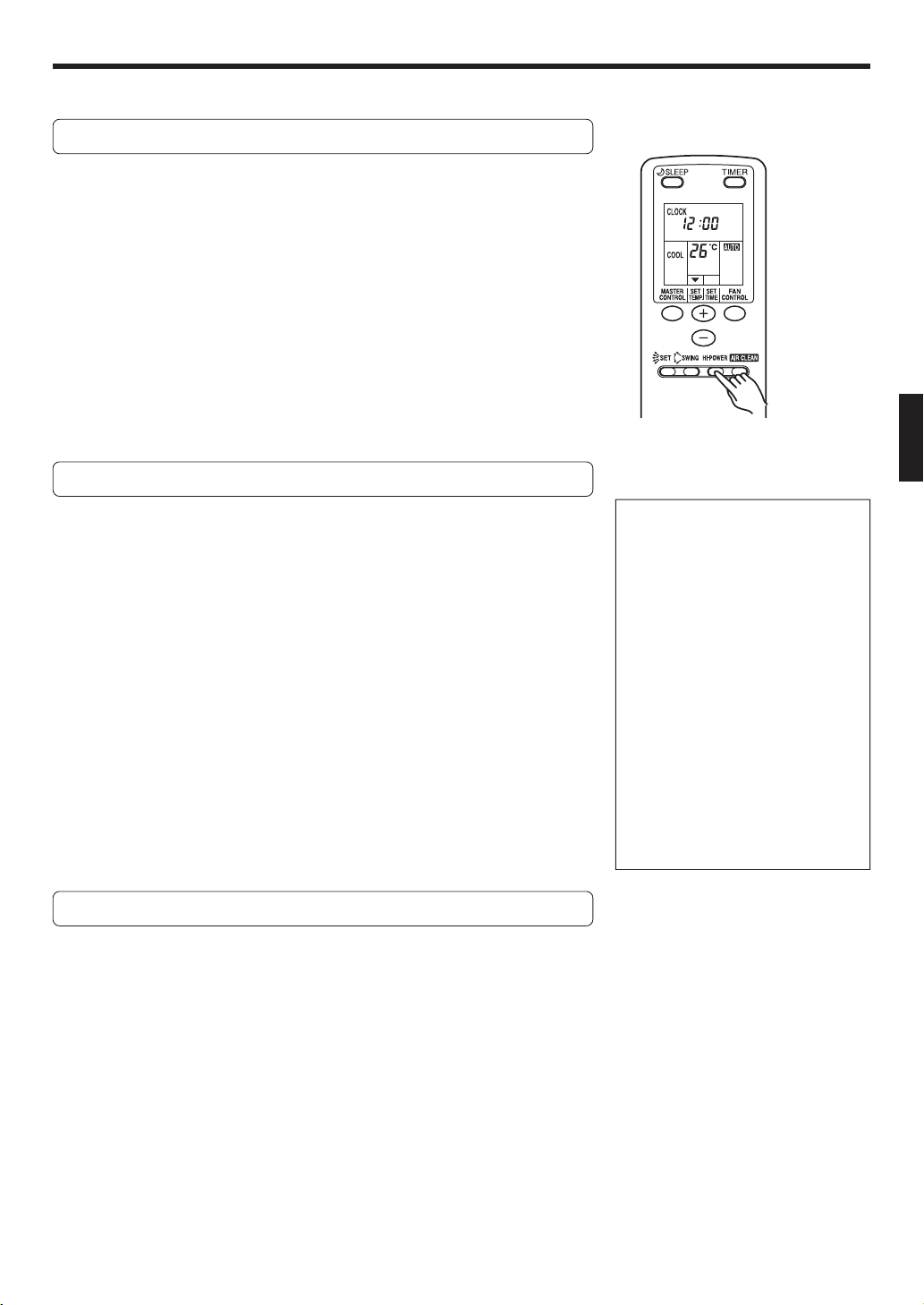
AIR CLEANING OPERATION
Example: When set to AUTO.
● Use this function to remove airborne impurities such as dust, tobacco smoke and pollen and clean the air of the room.
● The air cleaning operation can be used alone or combined with cooling, heating and dry (dehumidifying) operations.
Starting air cleaning operation
1
Start the operation in any one of the following: AUTO,
COOL, HEAT, DRY or FAN.
Refer to pages 5 and 6 for information about starting these operations.
2
Press the AIR CLEAN button. (Fig. 5 Y)
The indicator lamp for the clean air indicator will light up.
Stopping the air clean operation
Press the AIR CLEAN button.
The indicator lamp for the clean air indicator will go out.
About the clean air indicator
● The level of airborne contaminants in the room is monitored by the clean air indicator sensor
(Fig. 1 F) and displayed in the clean air indicator. When the air is clean, all the clean air
indicator lamps will be green. As the air becomes dirty, the number of red indicator lamps will
increase.
● After the power supply plug has been plugged in and the air cleaning operation has started, the clean air indicator sensor
will perform a preparation operation for approximately 3 minutes. (The same will occur when more than 6 hours have
passed after the operation has been stopped by the remote controller.) At this time, the sensor does not monitor the level of
airborne contaminants and the clean air indicator lamps will all be green. After 3 minutes of operation, the sensor will begin
to monitor the airborne contaminants and the condition of the air in the room will be displayed.
● When the air cleaning operation is being performed, the number of illuminated red indicator lamps will either increase or
decrease according to the condition of the air in the room and the operation of the remote controller.
● The clean air indicator does not respond to some contaminants.
Response by clean air indicator : Tobacco smoke, incense, aerosol sprays (insect sprays, cosmetic sprays), alcohol
(beverages, cooking, etc.), water vapor (from kitchen or bathroom) and others.
No response by clean air indicator : Dust, pollen, mold spores, mite particles and others.
Air cleaning
● During operation the unit produces a small amount of ozone that can be smelled.
● When this unit is used in combination with the dust collection unit, white particles will become attached to the dust collec-
tion unit. When this happens, clean the dust collection unit as soon as possible. (Refer to page 14.)
● The air cleaning unit cannot remove gases such as carbon dioxide and alcohol from the air. During operation, ventilate the
room often to prevent asphyxiation or suffocation.
● If the intake grille is opened during operation, a safety device will stop the operation of the air cleaning unit. When this
happens, the operation lamp (red) on the main unit will and the timer lamp (green) will flash and the temperature monitor
will display
. Use the START/STOP button on the remote controller to stop the operation, close the grille and then use the
START/STOP button to restart the operation.
● Use the FAN CONTROL button to change the fan speed. (Refer to page 5.) The air cleaning unit operates most effectively at
the highest fan speed.
● When the fan is set to automatic, the fan speed will change among three fan speeds in response to the output of the clean
air indicator. When the air in the room becomes clean, the air cleaning operation will be performed at the lowest fan speed.
● The clean air indicator will flash to inform you that the periodic cleaning of the dust collection unit is required. (Refer to Air
Clean Check Function, page 14.)
ROOM
TEMP.
CLEAN
AIR
POLLUTED
AIR
OPERATION
TIMER
SWING
AIR CLEAN INDICATOR
HI-POWER
Clean air indicator
Page 9
En-8
HI-POWER OPERATION
Example: When set to COOL.
Note that the hi-power operation will be
automatically cancelled under the
following conditions.
● During heating operations:
When the room temperature exceeds
the temperature setting by 2 °C.
● During cooling and dry operations:
When the room temperature is 1 °C
lower than the temperature setting or
when hi-power has been in operation
for more than 30 minutes since it was
set.
● During fan operation:
When hi-power has been in operation
for more than 15 minutes since it was
set.
Airflow direction and fan speed are set
automatically during hi-power operation.
However, the air flow direction can be
changed to a desired position by using
the airflow direction button. (Refer to page
11.)
● Start this operation after starting the operation of the unit.
To operate Hi-power
1
Start the operation in any one of the following: AUTO,
COOL, HEAT, DRY or FAN.
Refer to pages 5 and 6 for information about starting these operations.
2
Press the HI-POWER button. (Fig. 5 X)
The indicator lamp for hi-power (red) will light up.
To stop Hi-power
Press the HI-POWER button.
● The indicator lamp for hi-power (red) will go out.
● The unit will return to normal operation.
Hi-power operation
Heating : ● If the hi-power button is pressed immediately after starting op-
eration, the unit will enter the “downward airflow operation” for
15 minutes so that heating of low areas near the floor will be
performed at the highest power.
● After this time has been completed, the airflow direction will
change automatically so that the entire room can be heated evenly.
Cooling, Dry : ● Operates at maximum fan power until 1 °C before the setting tem-
perature and rapidly cools the room.
Fan : ● Increases the fan speed of the indoor unit.
Page 10

En-9
To Cancel the Timer
Use the TIMER button to select “TIMER
RESET.”
The air conditioner will return to normal
operation.
To Change the Timer Setting
1.
Follow the instructions given in the section
“To Use the ON Timer or OFF Timer” to select the timer setting you wish to change.
2. Press the TIMER button to select either
OFF → ON or OFF ← ON.
To Stop Air Conditioner Operation
while the Timer is Operating
Press the START/STOP button.
To Change Operating Conditions
If you wish to change operating conditions
(Mode, Fan Speed, Thermostat Setting),
after making the timer setting wait until the
entire display reappears, then press the
appropriate buttons to change the operating condition desired.
To Cancel the Timer
Use the TIMER button to select “TIMER
RESET”.
The air conditioner will return to normal
operation.
To Change the Timer Setting
Perform steps 2 and 3.
To Stop Air Conditioner Operation
while the Timer is Operating
Press the START/STOP button.
To Change Operating Conditions
If you wish to change the operating
conditions (Mode, Fan Speed, Thermostat
Setting), after making the timer setting wait
until the entire display reappears, then
press the appropriate buttons to change
the operating condition desired.
TIMER OPERATION
Before using the timer function, be sure that the Remote Control Unit is set to the correct current time (See page 4).
To Use the ON timer or OFF timer
1
Press the START/STOP button (Fig. 5 U)
(if the unit is already operating, proceed to step 2).
The indoor unit’s OPERATION Indicator Lamp (red) (Fig. 2 7) will light.
2
Press the TIMER button (Fig. 5 S) to select the OFF
timer or ON timer operation.
Each time the button is pressed the timer function changes in the following order:
RESET OFF ON
PROGRAM (OFF → ON, OFF ← ON)
The indoor unit’s TIMER Indicator Lamp (green) (Fig. 3 8) will light.
3
Use the SET TEMP. SET TIME button (Fig. 5 Q) to adjust the desired OFF time or ON time.
Set the time while the time display is flashing (the flashing will continue
for about five seconds).
button: Press to advance the time.
button: Press to reverse the time.
About five seconds later, the entire display will reappear.
To Use the Program timer
1
Press the START/STOP button (Fig. 5 U)
(if the unit is already operating, proceed to step 2).
The indoor unit’s OPERATION Indicator Lamp (red) (Fig. 2 7) will light.
2
Set the desired times for OFF timer and ON timer.
See the section “To Use the ON timer or OFF timer” to set the desired
mode and times.
About three seconds later, the entire display will reappear.
The indoor unit’s TIMER Indicator Lamp (green) (Fig. 2 8) will light.
3
Press the TIMER button (Fig. 5 S) to select the PROGRAM timer operation (either OFF → ON or OFF ← ON
will display).
The display will alternately show “OFF timer” and “ON timer”, then change
to show the time setting for the operation to occur first.
● The PROGRAM timer will begin operation. (If the ON timer has been
selected to operate first, the unit will stop operating at this point.)
About five seconds later, the entire display will reappear.
About the Program timer
● The PROGRAM timer allows you to integrate OFF timer and ON timer operations
in a single sequence. The sequence can involve one transition from OFF timer to
ON timer, or from ON timer to OFF timer, within a twenty-four hour period.
● The first timer function to operate will be the one set nearest to the current time.
The order of operation is indicated by the arrow in the Remote Control Unit’s
display (OFF → ON, or OFF ← ON).
● One example of PROGRAM timer use might be to have the air conditioner automatically stop (OFF timer) after you go to sleep, then start (ON timer) automatically in the morning before you arise.
t
sss
Page 11

En-10
SLEEP TIMER OPERATION
Unlike other timer functions, the SLEEP timer is used to set the length of time until air conditioner operate is stopped.
To Use the SLEEP Timer
While the air conditioner is operating or stopped, press the
SLEEP button (Fig. 5 O).
The indoor unit’s OPERATION Indicator Lamp (red) (Fig. 2 7) lights and the TIMER
Indicator Lamp (green) (Fig. 2 8) light.
To Change the Timer Settings
Press the SLEEP button (Fig. 5 O) once again and set the time
using the SET TIME buttons (Fig. 5 Q).
Set the time while the Timer Mode Display is flashing (the flashing will continue
about five seconds).
button: Press to advance the time.
button: Press to reverse the time.
About five seconds later, the entire display will reappear.
To Cancel the Timer:
Use the TIMER button to select “TIMER
RESET”.
The air conditioner will return to normal
operation.
To Stop the Air Conditioner During
Timer Operation:
Press the START/STOP button.
About the SLEEP Timer
To prevent excessive warming or cooling during sleep, the SLEEP timer function automatically modifies the thermostat setting
in accordance with the set time setting. When the set time has elapsed, the air conditioner completely stops.
During Cooling/Dry operation:
When the SLEEP timer is set, the thermostat setting is automatically raised 1 °C every sixty minutes. When the thermostat has been raised a total of 2 °C, the thermostat setting at
that time is maintained until the set time has elapsed, at which
time the air conditioner automatically turns off.
SLEEP timer setting
During Heating operation:
When the SLEEP timer is set, the thermostat setting is
automatically lowered 1 °C every thirty minutes. When the
thermostat has been lowered a total of 4 °C, the thermostat
setting at that time is maintained until the set time has elapsed,
at which time the air conditioner automatically turns off.
SLEEP timer setting
2 °C
3 °C
4 °C
30
minutes
1 °C
1 hour
1 hour
30 minutes
Set time
Set time
1 hour
1 °C
2 °C
Page 12

En-11
ADJUSTING THE DIRECTION OF AIR CIRCULATION
Vertical (up-down) direction of airflow is adjusted by pressing the Remote Control Unit’s AIR FLOW DIRECTION button. Horizontal (right-left) airflow direction is adjusted manually, by moving the Air Flow Direction Louvers.
Whenever making horizontal airflow adjustments, start air conditioner operation and be sure that the vertical air direction
louvers are stopped.
DANGER!
● Never place fingers or foreign objects inside the outlet ports, since the internal fan
operates at high speed and could cause
personal injury.
● Always use the remote control unit’s
AIR FLOW DIRECTION button to adjust
the vertical airflow louvers. Attempting
to move them manually could result in
improper operation; in this case, stop
operation and restart. The louvers
should begin to operate properly again.
● During use of the Cooling and Dry
modes, do not set the Air Flow Direction Louvers in the Heating range (4 -
7) for long periods of time, since water vapor may condense near the outlet louvers and drops of water may drip
from the air conditioner. During the
Cooling and Dry modes, if the Air Flow
Direction Louvers are left in the heating range for more than 30 minutes,
they will automatically return to position 3.
● When used in a room with infants, children, elderly or sick persons, the air
direction and room temperature
should be considered carefully when
making settings.
Vertical Air Direction Adjustment
Press the AIR FLOW DIRECTION button (Fig. 5 V).
Each time the button is pressed, the air direction range will change as follows:
1
2 3 4 5 6 7
Types of Air flow Direction Setting:
1,2,3 : During Cooling/Dry modes
3,4,5,6,7 : During Heating mode
The Remote Control Unit’s display does
not change.
● Use the air direction adjustments within the ranges shown above.
● The vertical airflow direction is set automatically as shown, in accordance with
the type of operation selected.
During Cooling/Dry mode : Horizontal flow 1
During Heating mode : Downward flow 6
● During AUTO mode operation, for the first minute after beginning operation,
airflow will be horizontal 1; the air direction cannot be adjusted during this period.
● When operating at hi-power (as shown on page 8) the louvers are automatically
set to the downward flow position in order to draw out the maximum heating or
cooling performance of the unit.
● When set to swing operation (as shown on page 12), the swing direction cannot
be changed even if the AIR FLOW DIRECTION button is pressed.
Right-Left Adjustment
Adjust the Right-Left louvers.
● Move the Right-Left louvers to adjust air flow in the direction you prefer.
Right-Left Louvers
1 Horizontal flow
7 Downward flow
Page 13

En-12
SWING OPERATION
Begin air conditioner operation before performing this procedure.
To select SWING Operation
Press the SWING LOUVER button (Fig. 5 W).
The SWING Indicator Lamp (orange) (Fig. 3 9) will light.
In this mode, the Air Flow Direction Louvers will swing automatically to direct the
airflow both up and down.
To Stop SWING Operation
Press the SWING LOUVER button (Fig. 5 W) once again.
The SWING Indicator Lamp (orange) (Fig. 3 9) will go out.
Airflow direction will return to the setting before swing was begun.
About Swing Operation
MANUAL AUTO OPERATION
Use the MANUAL AUTO operation in the event the Remote Control Unit is lost or otherwise unavailable.
How To Use the Main Unit Controls
Press the MANUAL AUTO button (Fig. 3 I) on the main unit
control panel.
To stop operation, press the MANUAL AUTO button once again.
(Controls are located inside the Intake Grille.)
● When the air conditioner is operated
with the controls on the Main Unit, it
will operate under the same mode as
the AUTO CHANGEOVER mode selected on the Remote Control Unit (see
page 6).
● During MANUAL AUTO operation, the
thermostat is automatically set at a
standard temperature setting (=24 °C).
● The fan speed selected will be “AUTO”
and the airflow direction will be the
standard direction (cooling:1, heating:6).
● If the operation does not start when the
MANUAL AUTO button is pressed
once, it is because the air cleaning
check function is operating. Press the
button once more to start operation.
Example: When set to 26 °C.
During cooling/Dry mode : Swings between 1 and 3.
During heating mode : Swings between 3 and 7.
● The SWING operation may stop temporarily when the air conditioner’s fan is not
operating or when operating at very low speeds.
● The airflow direction can not be adjusted during SWING operation even when
the AIR FLOW DIRECTION button is pressed.
Page 14

En-13
● Before cleaning the air conditioner, be sure to turn it off and disconnect the power supply cord.
● Be sure the intake grille (Fig. 1 1) is installed securely.
● When opening, closing or removing the intake grille, be cautious to prevent it from falling down.
● When removing and replacing the air filters, be sure not to touch the heat exchanger, as per-
sonal injury may result.
CLEANING AND CARE
CAUTION!
Cleaning the Intake Grille
1. Stop the operation with the remote con-
trol and disconnect the power supply cord.
2. Remove dust with a vacuum cleaner; wipe
the unit with warm water, then dry with a
clean, soft cloth.
● Do not remove the intake grille. Removing by force will
lead to damage.
● Do not move the panel by hand. Moving by force will
lead to damage. Dew may condense and water may drop
near the outlet port.
● Do not place anything on or inside the panel, this will
lead to damage.
2. Remove dust with a vacuum cleaner or by
washing.
After washing, allow to dry thoroughly in a shaded place.
3. Replace the Air Filter and close the Intake
Grille.
Align the sides of the Air Filter with the panel, and
push in fully, making sure the two lower tabs are
returned properly to their holes in the panel.
4. Close the Intake Grille.
Press on the four locations at the bottom of the grille to
securely close the intake grille. If the intake grille is not
closed securely, the temperature monitor will display a
and the operation of the air cleaning unit will be
stopped.
● Dust can be cleaned from the Air Filter either with a
vacuum cleaner, or by washing the filter in a solution
of mild detergent and warm water. If you wash the
filter, be sure to allow it to dry thoroughly in a shady
place before reinstalling.
● If dirt is allowed to accumulate on the Air Filter, air flow
will be reduced, lowering operating efficiency and
increasing noise.
● During periods of normal use, the Air Filters should be
cleaned every two weeks.
CAUTION
Do not stand on any unstable table when cleaning. This may lead to injury resulting from falling
down.
● If the intake grille is closed after finishing the work, the
open panel will remain open. In this case, connect the
power supply cord to the socket when the intake grille is
closed. The open panel will close.
Cleaning the Air Filter
1. Open the intake grille, and remove the air
filter.
Lift up the air filter’s handle, disconnect the two lower
tabs, and pull out.
Handle
Tabs
Handle
Tabs
Page 15

En-14
Make sure the dust collection unit is properly mounted before cleaning or performing other tasks
on it. If the unit is not properly mounted, it could fall off and cause damage or injury.
The display section for the clean air indicator will flash when it is time for the periodic cleaning of the dust collection unit.
• When the flashing of the display section for the clean air indicator is slow (approximately 1 flash every 4 seconds)
This will flash after approximately 400 hours of operation. Cleaning of the dust collection unit as soon as possible is
recommended.
• When the flashing of the display section for the clean air indicator is fast (approximately 1 flash every 2 seconds)
This will flash after approximately 500 hours of operation. Stop the air cleaning operation and clean the dust collection
unit.
● As a guideline, clean every 6 months.
● If unusual sounds (like the rushing of air or popping) are heard, clean the dust collection unit as quickly as possible.
● If the air cleaning check function is operating, open the intake grille and press the MANUAL AUTO button.
CLEANING THE PLASMA AIR CLEANING FILTER
CAUTION!
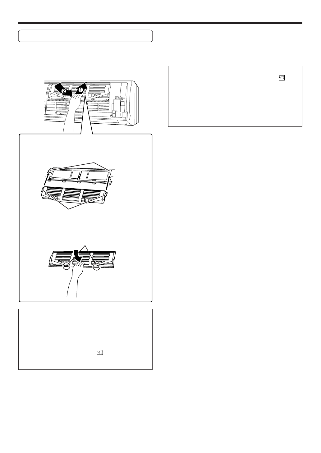
Removing the dust collection unit
1. Use the remote controller to stop operation and unplug the power cord.
2. Open the intake grill and remove the rightside air filter. (Refer to page 13.)
3. Remove the dust collection unit.
(Note that the figure below shows the unit without the
grille. This is for explanatory purposes only. The actual
intake grille cannot be removed.)
Grasp the handle of the dust collection unit. Pull up
(shown as direction 1) and then pull down (shown as
direction 2) to remove.
Handle
Cleaning the dust collection unit
Wash with water and dry.
1 Soak the dust collection unit in warm water (40 to 45
°C) for 10 to 15 minutes. If the dust collection unit is
extremely dirty, extremely dilute a mild synthetic laundry detergent (low or neutral alkalinity) to 15 times
the standard concentration and allow the dust collection unit to soak in it.
2 Gently move up and down and to the right and left. A
soft sponge can also be used to wipe the rear surface.
3 Rinse with clean water.
4 Shake the dust collection unit to drain off the water.
(If the dust collection unit is extremely dirty, repeat
Steps 1 through 4 two or three more times.)
5 Place the dust collection unit in the shade and allow
it to dry completely.
● Only use a mild synthetic laundry detergent (low or
neutral alkalinity).
● Never disassemble the dust collection unit.
● Never soak the dust collection unit in hot water.
● Never wipe the dust collection unit with a scrub brush
or other hard or abrasive items.
● Never insert a brush into the inside of dust collection
unit for washing. This will damage the thin fibers inside and cause malfunctioning of the air cleaning unit.
● Never use dryer or other device to blow hot air on the
dust collection unit. This will cause deformation or
other damage.
Page 16
En-15
Mounting the dust collection unit
1. Mount the dust collection unit.
(Note that the figure below shows the unit without the
grille. This is for explanatory purposes only. The actual
intake grille cannot be removed.)
1 Insert both of the insert sections of the dust collec-
tion unit into the guide rail.
Guide rail
Insert sections (2 locations)
2 Insert all the way to the back and then press in the
two tabs on the lower part until they snap into place.
Tabs (2 locations)
Snap
● Make sure the dust collection unit is completely dry
before mounting it.
● After the dust collection unit has been mounted into
place, make sure that the tabs on both sides are securely inserted in the frame. If the dust collection unit
is not properly mounted, the red operation lamp and
green timer lamp will flash, a
will be displayed in
the temperature monitor and the air cleaning operation will stop.
CLEANING THE PLASMA AIR CLEANING FILTER
2. Mount the air filter and close the intake
grille. (Refer to page 13.)
● After cleaning the dust collection unit, if the red operating lamp and green timer lamp flash and a
is displayed in the monitor, check if the dust collection unit
is wet or if the intake grilles is closed tightly.
● If the dust collection unit is completely dry and the intake grille is closed tightly but the lamps still flash, it is
probably due to damage to the dust collection unit.
The dust collection unit must be replaced. Contact your
sales representative for more information.
Snap
Page 17
En-16
CLEANING THE LIGHT-REGENERATED DEODORIZING FILTER
● The deodorizing effect of the light-regenerated deodorizing filter is restored by drying it in sunlight. (It is recommended that
this be done every 6 months.)
● If the deodorizing filter is used for an extended period of time and has become very dirty, its deodorizing performance will
be reduced. It is recommended that this filter be replaced approximately every 3 years. Replace this filter with the lightregenerated deodorizing filter sold separately (Model: UTR-FA07-1 Type).
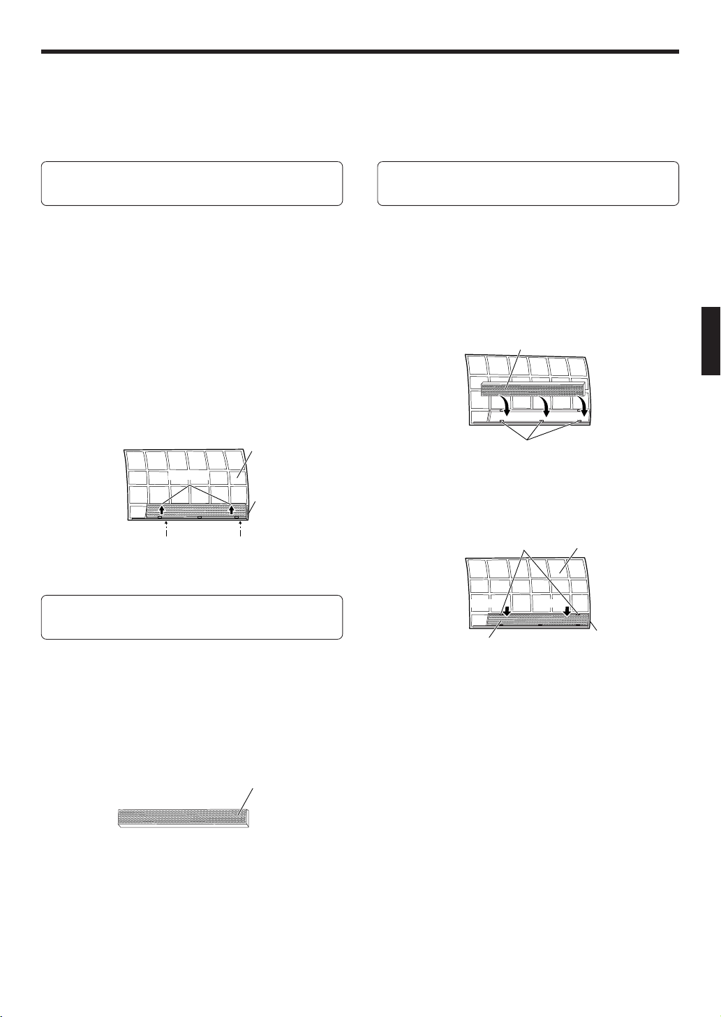
Removing the light-regenerated deodorizing filter
1. Use the remote controller to stop opera-
tion and unplug the power cord.
2. Open the intake grille and remove the
right-side air filter. (Refer to page 13.)
3. Remove the dust collection light-regener-
ated deodorizing filter.
1 Use your fingers to spread open the two tabs at the
top of the frame for the light-regenerated deodorizing
filter at the back of the air filter.
2 Use your fingers to push up on the bottom of the light-
regenerated deodorizing filter. (Do this to one side at
a time.)
Back of air filter
Light-regenerated
deodorizing filter
frame
Top tabs
Cleaning the light-regenerated deodorizing filter
1. Dry the light-regenerated deodorizing fil-
ter in direct sunlight.
● Dry the light-regenerated deodorizing filter in direct
sunlight.
● It is recommended that this filter be left in direct sunlight for 6 hours.
● Never wash the filter with water or other liquid.
Light-regenerated deodorizing filter
Mounting the light-regenerated deodorizing filter
1. Mount the light-regenerated deodorizing
filter to the back of the right-side air
cleaner.
Light-regenerated
deodorizing filter
1 Insert the edge of the light-regenerated deodorizing
filter onto the lower tabs of the light-regenerated deodorizing filter frame on the back of the air filter.
Light-regenerated deodorizing filter
Lower tabs
2 Use your fingers to push on the light-regenerated deo-
dorizing filter into place on the two upper tabs of the
light-regenerated deodorizing filter frame.
Upper tabs (2 locations)
Air filter
Light-regenerated
deodorizing filter frame
2. Mount the right-side air filter and close the
intake grille. (Refer to page 13.)
1 Use fingers to spread open.
2 Push up on the bottom.
Push Push
Page 18

En-17
TROUBLESHOOTING
In the event of a malfunction (burning smell, etc.), immediately stop operation, disconnect the
Power Supply Plug, and consult authorized service personnel.
Merely turning off the unit’s power switch will not completely disconnect the unit from the power
source. Always be sure to disconnect the Power Supply Plug or turn off your circuit breaker to
ensure that power is completely off.
Before requesting service, perform the following checks:
WARNING!
Symptom
Doesn’t operate immediately:
Noise is heard:
Smells:
Mist or steam are
emitted:
Airflow is weak or stops:
Water is produced from
the outdoor unit:
Problem
● If the unit is stopped and then immediately started again, the compressor will not operate for about 3 minutes, in order to prevent
fuse blowouts.
●
Whenever the Power Supply Plug is disconnected and then reconnected to a power outlet, the protection circuit will operate for
about 3 minutes, preventing unit operation during that period.
● During operation and immediately after stopping the unit, the
sound of water flowing in the air conditioner’s piping may be
heard. Also, noise may be particularly noticeable for about 2 to 3
minutes after starting operation (sound of coolant flowing).
● During operation, a slight squeaking sound may be heard. This is
the result of minute expansion and contraction of the front cover
due to temperature changes.
●
During Heating operation, a sizzling sound may be heard occasional.
This sound is produced by the Automatic Defrosting operation.
● Some smell may be emitted from the indoor unit. This smell is
the result of room smells (furniture, tobacco, etc.) which have
been taken into the air conditioner.
● The operation of the air cleaning unit produces a small amount
of ozone which can be smelled.
● During Cooling or Dry operation, a thin mist may be seen emitted
from the indoor unit. This results from the sudden Cooling of
room air by the air emitted from the air conditioner, resulting in
condensation and misting.
● During Heating operation, the outdoor unit’s fan may stop, and
steam may be seen rising from the unit. This is due to Automatic
Defrosting operation.
● When Heating operation is started, fan speed is temporarily very
low, to allow internal parts to warm up.
● During Heating operation, the unit will temporarily stop operation (between 7 and 15 minutes) as the Automatic Defrosting mode
operates. During Automatic Defrosting operation, the OPERATION
Indicator Lamp will flash.
● The fan may operate at very low speed during Dry operation or
when the unit is monitoring the room’s temperature.
● During SUPER QUIET operation, the fan will operate at very low
speed.
● In the monitor AUTO operation, the fan will operate at very low
speed.
● During Heating operation, water may be produced from the outdoor unit due to Automatic Defrosting operation.
See Page
—
—
20
—
—
20
—
20
5
5
5
20
NORMAL
FUNCTIONS
Page 19
En-18
Symptom
The outdoor unit does
not stop even when
heating operation is
stopped:
Flashing green lamp on
clean air indicator:
Problem
● When there is frost on the outdoor unit when heating operation
is stopped, defrosting will be performed automatically.
At this time, OPERATION Indicator Lamp will flash, and operation
will stop after the outdoor unit has run for several minutes.
● This lamp will flash slowly after approximately 400 hours of operation of the clean air indicator.
Stop the operation, unplug the power cord and clean the dust
collection unit and deodorizing filter.
● This lamp will flash rapidly after approximately 500 hours of operation of the clean air indicator.
The air cleaning operation will be stopped when this flashing
occurs. Make sure the operation is stopped, unplug the power
cord and clean the dust collection unit and deodorizing filter.
See Page
20
14
NORMAL
FUNCTIONS
Page 20
En-19
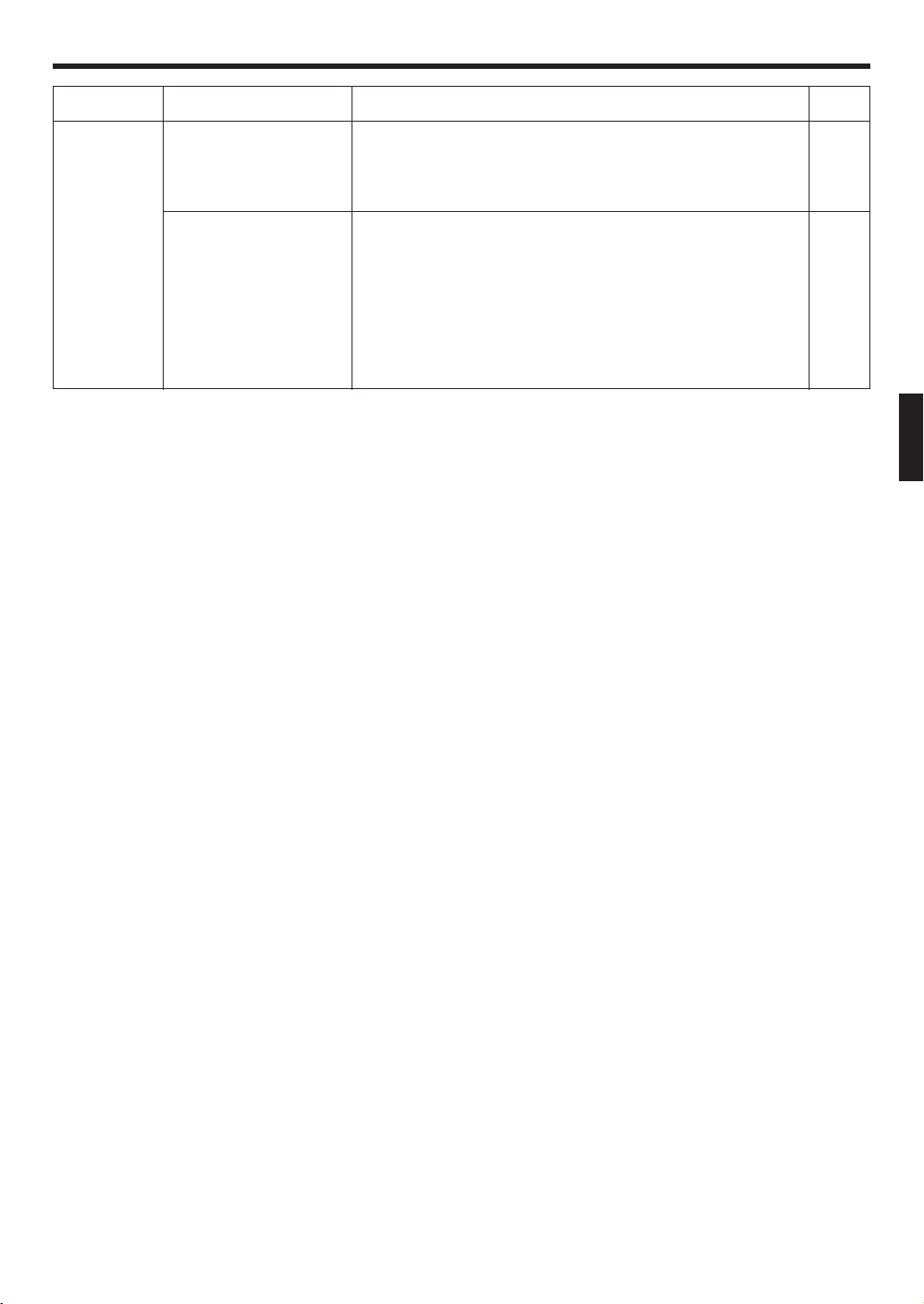
TROUBLESHOOTING
Symptom
Doesn’t operate at all:
Poor Cooling (or Heating)
performance:
The unit operates
differently from the remote
control unit’s setting:
Light clean air indicator color:
The clean air indicator
will display the following
during operation:
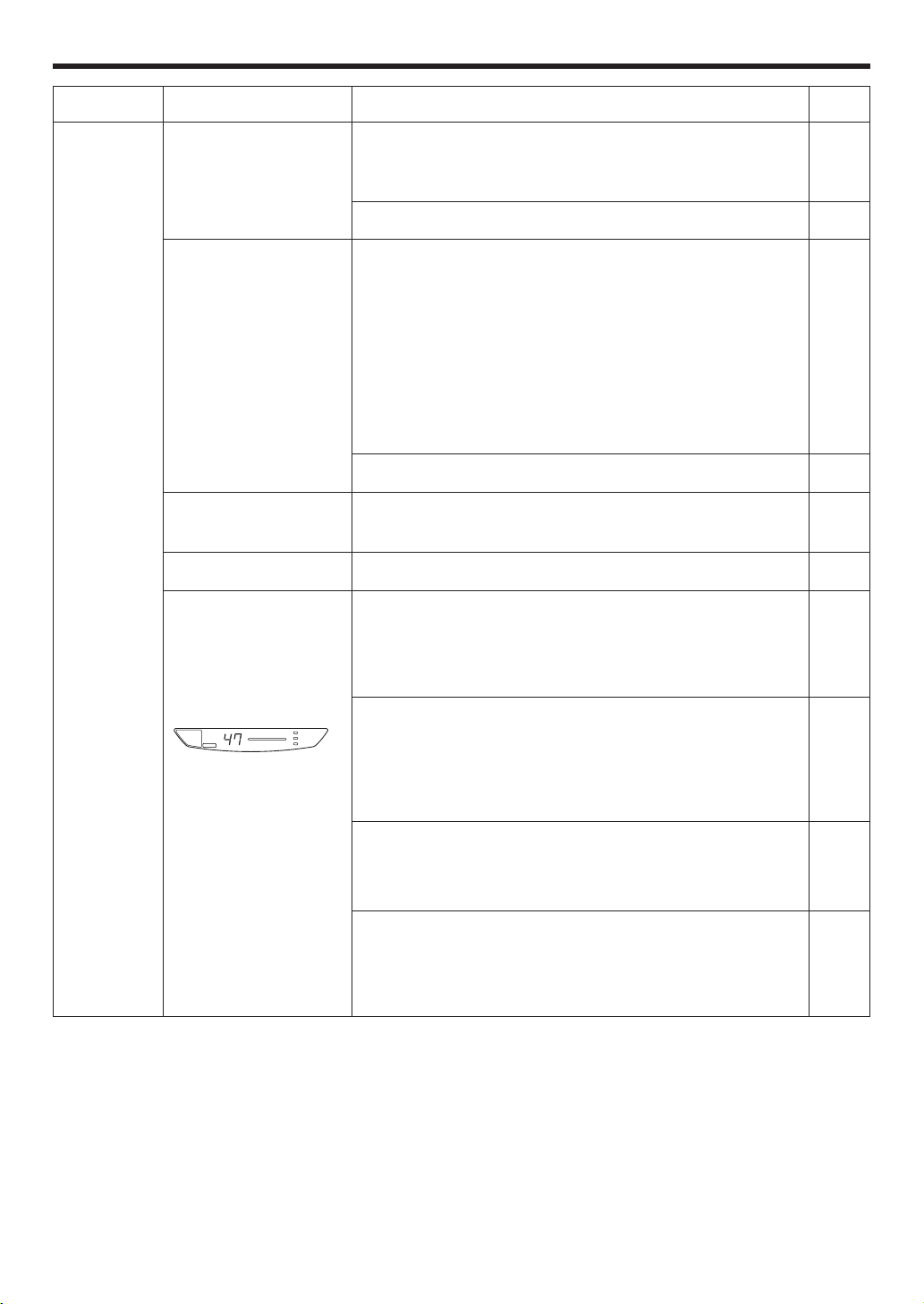
Indicator
OPERATION Indicator
Lamp (Red) :
4 flashes
Timer Indicator Lamp
(Green): Rapid flashing
Temperature: 47
CHECK ONCE
MORE
Items to check
● Is the Power Supply Plug disconnected from its outlet?
● Has there been a power failure?
● Has a fuse blown out, or a circuit breaker been tripped?
● Is the timer operating?
● Is the air filter dirty?
● Are the air conditioner’s intake grille or outlet port blocked?
● Did you adjust the room temperature settings (thermostat) cor-
rectly?
● Is there a window or door open?
● In the case of Cooling operation, is a window allowing bright sun-
light to enter? (Close the curtains.)
● In the case of Cooling operation, are there heating apparatus and
computers inside the room, or are there too many people in the
room?
● Is the unit set for SUPER QUIET operation?
● Are the Remote Control Unit’s batteries dead?
● Are the Remote Control Unit’s batteries loaded properly?
● Is the intake grille tightly closed?
● Is the intake grille tightly closed?
If the intake grille is opened during operation, a safety device will
stop the operation of the air cleaning unit. Use the remote controller to stop the operation, close the grille and then restart the
operation.
● Is the dust collection unit wet?
For safety reasons, the safety device will stop the air cleaning
operation if the dust collection unit is wet. Use the remote controller to stop the operation, remove the dust collection unit, dry
it completely and then remount. Start the air cleaning operation
again.
● Is the dust collection unit dirty?
If the dust collection unit is dirty, its dust collecting performance
will be reduced. Clean the dust collection unit and restart the operation.
● Is the dust collection unit not securely mounted?
For safety reasons, the safety device will stop the air cleaning
operation if the dust collection unit is not securely mounted. Use
the remote controller to stop the operation and securely mount
the dust collection unit. Restart the operation.
If the problem persists after performing these checks, or if you notice burning smells, or the TIMER Indicator Lamp (Fig. 2 8)
flashes, immediately stop operation, disconnect the Power Supply Plug (Fig. 1 D), and consult authorized service personnel.
ROOM
TEMP.
CLEAN
AIR
POLLUTED
AIR
OPERATION
TIMER
SWING
AIR CLEAN INDICATOR
HI-POWER
See Page
—
9 - 10
—
5
4
13
13
14
14
15
Page 21
En-20
In Event of Power Interruption
AUTO Restart
Dry Mode
About 10-43 °C
About 18-32 °C
Outdoor temperature
Indoor temperature
Cooling Mode
About 10-43 °C
About 18-32 °C
● If the air conditioner is used under higher temperature conditioner than those listed, the built-in protection circuit may
operate to prevent internal circuit damage. Also, during Cooling and Dry modes, if the unit is used under conditions of
lower temperature than those listed above, the heat-exchanger may freeze, leading to water leakage and other damage.
● Do not use this unit for any purposes other than the Cooling, Heating, Dehumidifying, and air-circulation of rooms in
ordinary dwellings.
● If the unit is used for long periods under high-humidity conditions, condensation may form on the surface of the indoor
unit, and drip onto the floor or other objects underneath. (About 80% or more)
Heating Mode
About –5-24 °C
About 30 °C or less
Operation and Performance
OPERATING TIPS
● The air conditioner power has been interrupted by a
power failure. The air conditioner will then restart automatically in its previous mode when the power is restored.
● If a power failure occurs during TIMER operation, the timer
will be reset and the unit will begin (or stop) operation at
the new time setting. In the event that this kind of timer
fault occurs, the TIMER Indicator Lamp (green) will flash
(see page 3).
● Use of other electrical appliances (electric shaver, etc.) or
nearby use of a wireless radio transmitter may cause the
air conditioner to malfunction. In this event, temporarily
disconnect the Power Supply Plug, reconnect it, and then
use the Remote Control Unit to resume operation.
Heating Performance
● This air conditioner operates on the heat-pump principle,
absorbing heat from outdoor air and transferring that heat
indoors. As a result, the operating performance is reduced
as outdoor air temperature drops. If you feel that insufficient heating performance is being produced, we recommend you use this air conditioner in conjunction with
another kind of heating appliance.
● Heat-pump air conditioners heat your entire room by
recirculating air throughout the room, with the result that
some time may be required after first starting the air conditioner until the room is heated.
Microcomputer-controlled Automatic Defrosting
● When using the Heating mode under conditions of low
outdoor air temperature and high humidity, frost may
form on the outdoor unit, resulting in reduced operating
performance.
In order to prevent this kind of reduced performance, this
unit is equipped with a Microcomputer-controlled Automatic Defrosting function. If frost forms, the air conditioner will temporarily stop, and the defrosting circuit will
operate briefly (for about 7-15 minutes).
During Automatic Defrosting operation, the OPERATION
Indicator Lamp (red) will flash.
Temperature and Humidity Range
 Loading...