

Page 1

R410A
6 . DUCT TYPE
AR 60FUAK, AR 60UUAK
ART60UUAK
D2D_AR010E/04
2006.05.30
Page 2
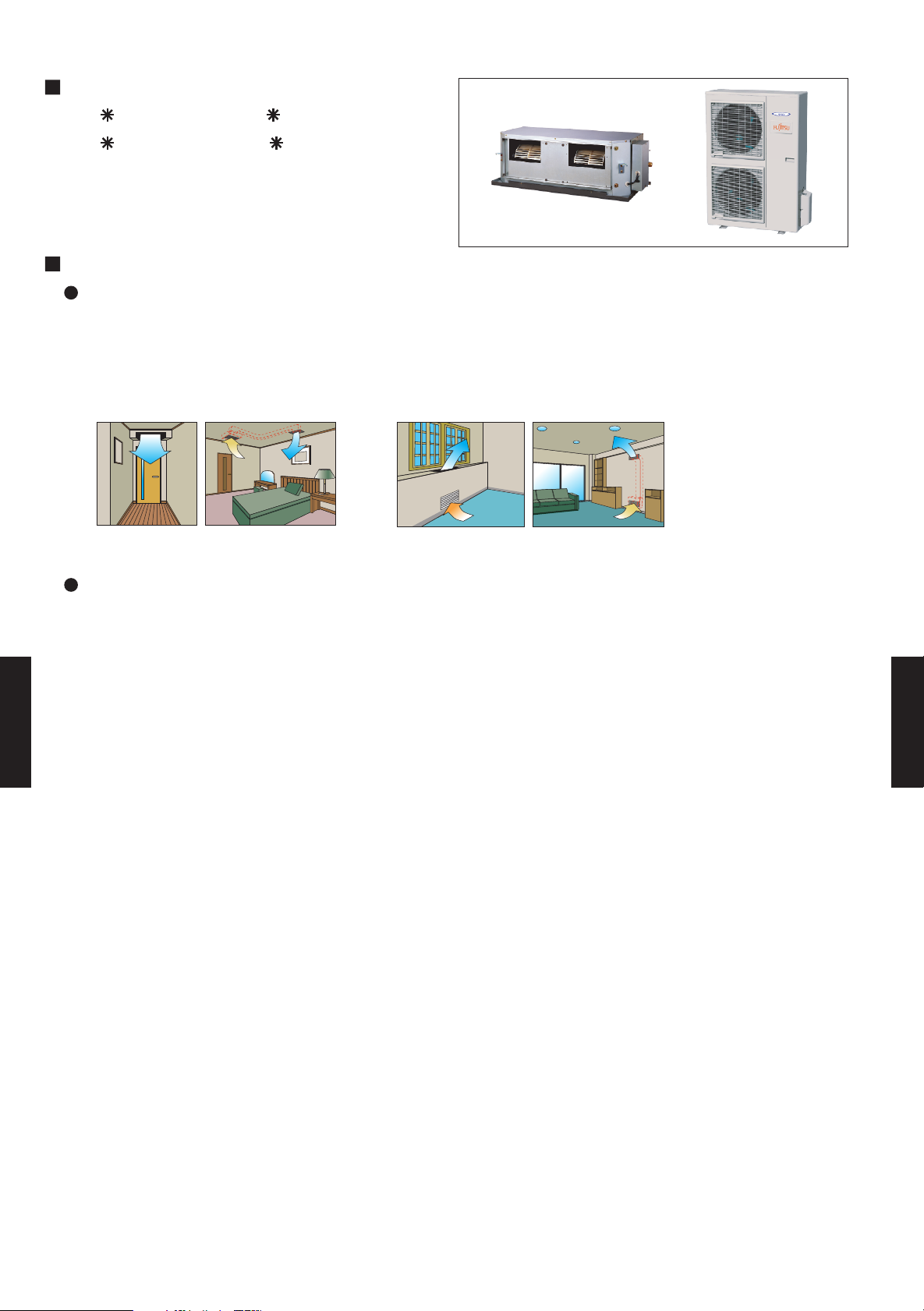
6-1. FEATURE
MODELS :
AR 60FUAK / AO 60FMAYT
AR 60UUAK / AO 60UMAYT
ART60UUAK / AOT60UMAYT
FEATURES
Universal design indoor unit
Since vertical and horizontal installation is possible, and the intake direction can also be selected
from two directions, flexible installation is possible.
Ceiling concealed Floor concealed
Thin and compact indoor unit
DUCT TYPE
AR60
DUCT TYPE
AR60
- (06 - 01) -
Page 3

6-2. REMOTE CONTROLLER
6-2-1. WIRED REMOTE CONTROLLER
FEATURES
Various timer setup (ON / OFF / WEEKLY) are possible.
Equipped with weekly timer as standard function.
(2 times Start / Stop per day for a week)
SUMOTUWETH FR SA
7
3126 9
15 18 21
When setting up a timer, operation mode and a temperature
setup can be changed.
When a failure occurs,the error code is displayed. (Maximum of 16)
Error indication.(A maximum of 16 error histories are memorizable.)
Up to 16 indoor units can be simultaneously controlled.
Anti freeze and energy saving operation are possible.
Easy installation with a slim shape with no boldge in the back.
The room temperature can be controlled by being detected the temperature
accurately with built-in thermo sensor.
High performance and compact size
Three functions are combined in
one unit.
Wired
remote
controller
Built-in timers
Weekly
timer
Setback timerWeekly timer
Setback
timer
Possible to set ON/OFF time to operate twice each day
of the week.
SUMOTUWETH FR SA
7
3126 9
15 18 21
Setup screen example
(Set to Wednesday: 8:00 to 20:00.)
DUCT TYPE
AR60
0 3 6 9 12 15 18 21 Time
Easy-to-understand time bar display
24°C
SUMOTUWETH FR SA
7
3126 9
15 1821
Screen
after setup
Possible to set temperature for two time spans and
for each day of the week.
SUMOTUWETH FR SA
3126 9
15 18 21
Setup screen example
(Set from Sunday to Saturday: 12:00 to 15:00, 28 °C.)
28°C
0 3 6 9 12 15 18 21 Time
DUCT TYPE
AR60
At "Weekly timer" + "Set back timer" setup
24°C
24°C 28°C 24°C
0 3 6 9 12 15 18 21 Time
28°C
Easy-to-understand operation Simple installation
Components are compatible with standard
switch boxes. Flat back construction allows
equipment to be installed wherever it is
Timer
area
Operation
area
needed.
[
Variable timer control
]
The operation/display sections are zoned according to time and operation, enabling variable programming to match application.
- (06 - 02) -
European
switch box
JIS box
Page 4
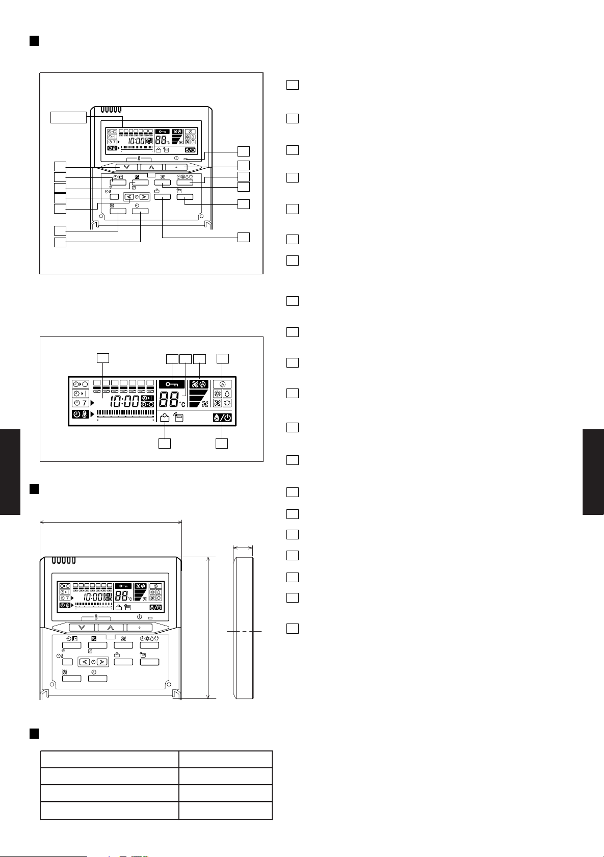
FUNCTIONS
1
START/STOP button
Pressed to start and stop operation.
Display
2
7
8
9
10
11
12
Display panel
14
SUMOTUWETH FR
CLOCK ADJUST
SET BACK
DELETE SET
369
SUMOTUWETH FR
369
12 15 18 21
DAY OFF
12 15 18 21
2
SA
13
DAY
ENERGY
THERMO
SAVE
SENSOR
1
3
4
6
Set temperature button
Selects the setting temperature.
3
Master control button
Selects the operating mode(AUTO, HEAT, FAN, COOL, DRY).
4
Fan control button
Selects the fan speed (AUTO, LOW, MED, HIGH).
5
Energy save button
Turns the energy efficient mode on and off.
5
6
Thermo sensor
7
Timer mode (CLOCK ADJUST) button
Selects the timer mode (OFF TIMER, ON TIMER, WEEKLY TIMER)
Set the current time.
8
Day (DAY OFF) button
Temporarily cancels of one day timer.
9
Set back button
pressed select the set back timer.
15
1617 18
10
Set time button
Pessed to select the set back timer.
SA
11
Delete button
The schedule of a weekly timer is deleted.
12
Set button
1920
Sets the date, hour, minute and on-off time.
13
Operation lamp
Lights during operation and when the timer is on.
DIMENSION
DUCT TYPE
AR60
SUMOTUWETH FR
CLOCK ADJUST
SET BACK
DELETE SET
369
12 15 18 21
DAY
DAY OFF
120
SA
ENERGY
THERMO
SAVE
SENSOR
[ Unit : mm ]
17
120
14
Timer and clock display
15
Operation mode display
16
Fan speed display
17
Central control display
18
Temperature display
19
Stand by display
Indicates during the oil recovery and defrosting operation.
20
Energy save display
DUCT TYPE
AR60
Front View
SPECIFICATION
SIZE (H x W x D mm) 120 x 120 x 17
WEIGHT ( g ) 160
CABLE LENGTH ( m )
POWER ( V )
10
12
- (06 - 03) -
Page 5

6-3.
AR 60FUAK AR 60UUAK ART 60UUAK
AO 60FMAYT AO 60UMAYT AOT60UMAYT
3N 415V 50Hz
16.5
56300
19.7
67200
6.20
5.75
10.9
10.6
70
2.66
3.43
3600
3200
2650
6500
55/57
Rows x Stages x
Fin Pitch
Rows x Stages x
Fin Pitch
Beige (10YR7.5/1.0NN)
Fan motor thermal protector,Fuse
-10 to 24
1430 x 1050 x 445
118 (260) / 125 (275)
9.52(3/8 inc.)
50 (chargeless:20m)
R410A
0 to 43
3.7
Plate fin coil
1260 x 900 x 36.2
2 x 60 x 1.3
30
1290 x 900 x 330
Corrosion resistant coating
460 x 1230 x 640
50 (110) / 55 (121)
400 x 1050(1150)* x 500(585)*
Fan motor thermal protector,Fuse
49 / 49
45 / 45
Hydrophilic coating
336 x 890 x 53.2
42 / 42
SCROLL
4600
Three Phase
Plate fin coil
4 x 16 x 1.45
DRAIN PIPE
MATERIAL
SIZE
Steel
Outer diameter 25.4mm / Inner diameter 21.5mm
kg(lbs)
OUTDOOR
INDOOR
-
WIRED (AR-3TA1)
Synthetic (POE oil)
FLARE
19.05(6/8 inc.)
PIPE
SIZE
mm
SAFETY DEVICES
NET /
GROSS
CONNECTION METHOD
CASING COLOR
mm
kW
CURRENT
STARTING CURRENT
MOISTURE REMOVAL
W/W
A
OPTIONS
FAN TYPE x Q'ty
FAN MOTOR OUTPUT
W
WEIGHT
NET
GROSS
MAX HEIGHT
MAX LENGTH
HEATING
CAPACITY
COMPRESSOR
RECOMMENDED STATIC PRESSURE @ high
RATED
INPUT POWER
INDOOR
STARTING METHOD
dB(A)
DIMENSIONS
H × W × D
INDOOR
TYPE
OUTDOOR
m3/h
MODEL NAME
INDOOR
OUTDOOR
TYPE
DUCTED MODELS
HEAT PUMP TYPE
3N 400V 50Hz
RATED
POWER SOURCE
COOLING
NOISE LEVEL
(SOUND
PRESSURE)
COOL/HEAT
OUTDOOR
AIR
CIRCULATION
REMOTE CONTROLLER
TYPE
REFRIGERANT OIL
OPERATION(OUTDOOR)
°C
REFRIGERANT
TYPE
Coil
HEAT
EXCHANGER
TYPE
INDOOR
Surface treatment
OUTDOOR
Coil
Surface treatment
Hot-dipped galvanized steel sheet
3500
3000
2460
6300
Sirocco x 2
Propeller x 2
100 to 250
540
67
SPECIFICATIONS
COOLING TYPE
kW 16.5 16.5
BTU/h 56300 56300
kW - 19.5
BTU/h - 66600
COOLING RATED 5.93 6.06
HEATING RAT ED - 5.54
COOLING RATED 10.0 10.2
HEATING RAT ED - 9.8
A 70 70
EER COOLING 2.78 2.72
COP HEATING - 3.52
l/h (pints/h) 4.0(1.9) 4.0(1.9) 4.0(1.9)
High
Med
Low
Pa
INDOOR
OUTDOOR
INDOOR
OUTDOOR
High
Med
Low
54 / - 54 / 56
OUTPUT W
mm
Coil Dimensions mm
-
mm
Coil Dimensions mm
INDOOR
DUCT TYPE
AR60
INDOOR
OUTDOOR
INDOOR
OUTDOOR
INDOOR
OUTDOOR
OUTDOOR
INDOOR
OUTDOOR
LIQUID
GAS
m
m
CHARGE kg 3.5
DUCT TYPE
AR60
Note: Specifications are based on the following conditions.
Cooling: Indoor temperature of 27 °CDB / 19 °CWB,and outdoor temperature of 35 °CDB/24 °CWB.
Heating: Indoor temperature of 20 °CDB / 15 °CWB,and outdoor temperature of 7 °CDB/6 °CW B.
Standard static pressure : 100 Pa.
Pipe length : 7.5 m, Height difference : 0 m.(Outdoor unit - Indoor unit)
dimensions( )* are indicated the including flange,control box,safety drain pan.
COOLING
HEATING
WIRED (AR-3TA2)
mm
Remote Sensor (UTD-RS100F/UTD-RS100G)
Long Life Filter (UTD-LF60K/UTB-LF60KA)
Wire Set (UTD-ECS5A)
Simple remote controller
(UTB-YRB/UTB-GRB)
Simple remote controller
(UTB-YPB/UTB-GPB)
(UTB-YPB/UTB-GPB)
- (06 - 04) -
Simple remote controller
(UTB-TPB)
Page 6
6-4. DIMENSIONS
6-4-1. OUTDOOR UNIT
MODELS : AO 60F , AO 60U , AOT60U
Top view
900
1290
21
77 31
(Unit : mm)
12330
9
Front view
Air flow
370
DUCT TYPE
AR60
Drain cap
mounting places
Drain cap
mounting place
4-Ø12mm hole
Bottom view
400
Side view
151
170
DUCT TYPE
196
99
AR60
MOUNTING POSITION
When there are
obstacles at the
back or front side.
When there are obstacles
at the back and front sides.
When there are obstacles at
the back, side(s), and top.
When there are obstacles
at the back side with the
installation of more than
one unit.
100 mm
or more
600 mm
or more
100 mm
or more
100 to 300 mm *
* If the space is larger than that is stated, the condition
will be the same as that there are no obstacles.
25
0
(
Se
m
m
r
v
or
i
c
e
mor
s
pac
e
e
)
- (06 - 05) -
600 to 1000 mm
300 mm
or more
250 mm
or more
250 mm
or more
300 mm
or more
Page 7
6-4-2. INDOOR UNIT
MODELS : AR 60F , AR 60U , ART60U
Front view
(Unit : mm)
Top view
Side view (R)
Side view (L)
DUCT TYPE
AR60
Rear view
DUCT TYPE
AR60
MOUNTING POSITION
20 mm or over
450
(Service apace)
MAINTENANCE HOLE
Maintenance hole
450 mm
Control box
500 mm
500 mm
- (06 - 06) -
Page 8
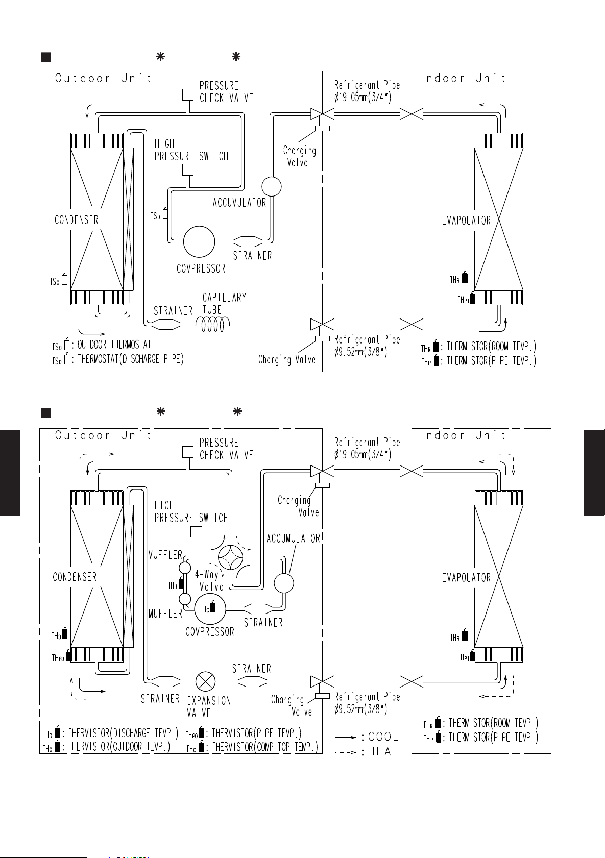
6-5. REFRIGERANT CIRCUIT
MODELS : AR 60F / AO 60F
MODELS : AR 60U / AO 60U , ART60U / AOT60U
DUCT TYPE
AR60
DUCT TYPE
AR60
- (06 - 07) -
Page 9

6-6. WIRING DIAGRAMS
6-6-1. OUTDOOR UNIT
MODEL : AO 60F
OUTDOOR UNIT POWER SUPPLY
415 V
400 V
INDOOR UNIT OUTPUT
240 V
230 V
MODELS : AO 60U, AOT60U
DUCT TYPE
AR60
DUCT TYPE
AR60
OUTDOOR UNIT POWER SUPPLY
415 V
400 V
- (06 - 08) -
INDOOR UNIT OUTPUT
240 V
230 V
Page 10

6-6-2. INDOOR UNIT
MODEL : AR 60F
DUCT TYPE
AR60
DUCT TYPE
AR60
- (06 - 09) -
Page 11

MODEL : AR 60U
DUCT TYPE
AR60
DUCT TYPE
AR60
- (06 - 10) -
Page 12

MODEL : ART60U
DUCT TYPE
AR60
DUCT TYPE
AR60
- (06 - 11) -
Page 13

6-7. CAPACITY TABLE
22 °CWB
21 °CWB
23 °CDB
30 °CDB
29 °CDB
32 °CDB
23 °CWB
18 °CWB
19 °CWB
21 °CDB
15 °CWB
26 °CDB
27 °CDB
16 °CWB
15 °CWB
32 °CDB
23 °CWB
22 °CWB
16 °CWB
18 °CWB
19 °CWB
21 °CWB
30 °CDB
21 °CDB
23 °CDB
26 °CDB
27 °CDB
29 °CDB
Outdoor temperature
Indoor temperature
Outdoor temperature
Indoor temperature
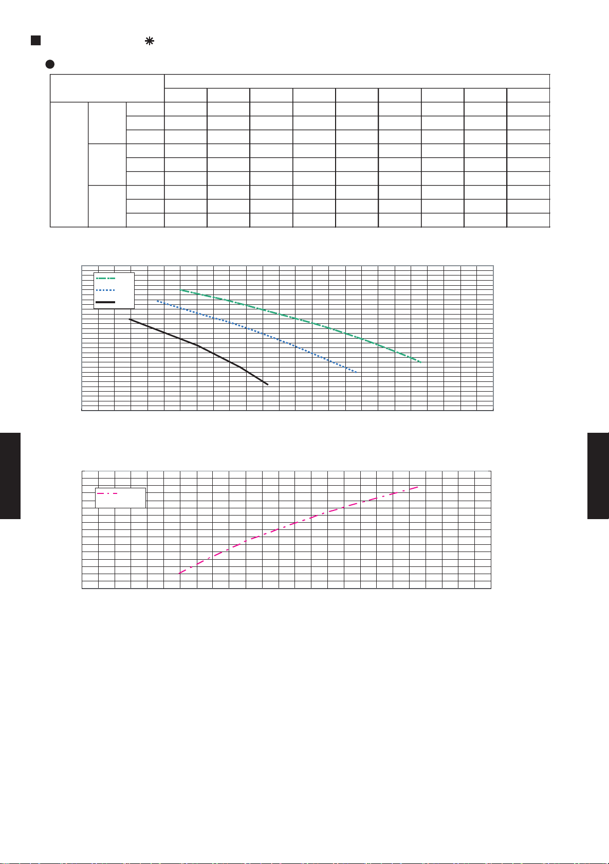
6-7-1. COOLING
MODELS : AR 60F / AO 60F
AFR 58.3
(°CDB)
0 18.48 13.99 3.58 19.18 15.15 3.63 20.65 16.35 3.75 21.30 16.30 3.82 22.45 16.64 3.93 22.99 16.83 3.97 23.39 17.91 3.99
5 17.58 13.55 3.99 18.24 14.70 4.04 19.64 15.88 4.16 20.38 15.96 4.23 21.49 16.14 4.40 22.14 16.47 4.46 22.66 17.68 4.50
10 16.68 13.12 4.42 17.30 14.27 4.47 18.65 15.48 4.60 19.33 15.51 4.67 20.50 15.78 4.87 21.07 16.03 4.96 21.67 17.34 5.01
15 15.74 12.68 4.86 16.34 13.83 4.92 17.60 15.01 5.05 17.29 14.09 5.12 19.42 15.44 5.35 19.96 15.65 5.47 20.56 16.98 5.53
20 14.79 11.15 5.30 15.34 12.17 5.37 16.54 13.13 5.51 17.17 13.06 5.59 18.26 13.40 5.86 18.81 13.62 5.98 19.38 14.89 6.05
25 15.91 15.91 4.79 16.60 16.60 4.82 18.03 18.03 4.89 18.79 18.79 4.93 19.93 19.93 5.12 20.59 20.59 5.17 21.09 21.09 5.20
30 14.93 11.80 5.25 15.57 12.94 5.29 16.95 14.14 5.37 17.66 14.18 5.41 18.80 14.60 5.64 19.45 14.92 5.69 19.97 16.14 5.73
35 13.90 11.30 5.72 12.63 10.57 5.76 15.83 13.64 5.85 16.50 13.77 5.93 17.57 14.15 6.17 18.22 14.46 6.23 18.72 15.68 6.27
40 12.75 10.76 6.19 13.37 11.92 6.24 14.66 13.14 6.34 15.20 13.32 6.48 16.35 13.77 6.70 16.92 14.03 6.76 17.34 15.18 6.81
43 12.01 10.41 6.47 14.50 13.45 6.52 13.84 12.85 6.68 14.39 13.05 6.82 15.56 13.54 7.02 16.07 13.74 7.08 16.48 14.88 7.13
TC SHC PI TC SHC PI TC SHC PI TC SHC PI TC SHC PI TC SHC PI TC SHC PI
MODELS : AR 60U / AO 60U , ART60U / AOT60U
AFR 58.3
(°CDB)
0 16.59 12.76 4.57 16.92 13.69 4.60 17.51 14.48 4.65 17.81 14.37 4.67 18.35 14.10 4.70 18.60 13.96 4.70 18.88 14.82 4.72
5 14.78 11.83 4.80 15.01 12.75 4.82 15.43 13.51 4.86 15.70 13.41 4.89 16.03 13.10 4.88 16.27 12.99 4.89 16.40 13.82 4.87
10 14.31 11.60 5.33 14.62 12.56 5.38 15.08 13.35 5.46 15.26 13.21 5.48 15.67 12.95 5.52 15.85 12.87 5.54 15.95 13.64 5.52
15 15.71 12.31 4.92 16.04 13.26 4.94 16.73 14.12 4.98 17.16 14.07 5.02 17.70 13.82 5.03 18.10 13.75 5.05 18.30 14.59 5.05
20 15.26 12.07 5.45 15.61 13.04 5.48 16.31 13.92 5.55 16.66 13.84 5.58 17.28 13.64 5.63 17.60 13.54 5.65 17.90 14.42 5.67
25 16.75 12.87 5.08 17.24 13.90 5.10 19.59 16.31 5.13 18.72 14.92 5.15 19.71 14.89 5.17 20.22 14.92 5.18 20.69 15.88 5.18
30 15.93 12.56 5.62 16.38 13.61 5.65 17.32 14.65 5.70 17.80 14.66 5.73 18.73 14.66 5.77 19.19 14.68 5.79 20.98 17.04 5.81
DUCT TYPE
AR60
35 14.86 11.87 6.54 15.28 12.88 5.96 16.11 13.82 0.67 16.50 13.77 6.06 17.32 13.74 6.13 17.69 13.69 6.14 18.05 14.63 6.17
40 13.75 11.31 6.35 14.12 12.31 6.40 14.84 13.24 6.49 15.20 13.18 6.53 15.85 13.05 6.60 16.18 13.02 6.63 16.47 13.95 6.67
43 12.48 10.68 5.92 12.89 11.71 6.59 13.68 12.70 6.04 14.06 12.67 6.70 14.54 12.47 6.77 14.77 12.37 6.80 14.98 13.25 6.83
TC SHC PI TC SHC PI TC SHC PI TC SHC PI TC SHC PI TC SHC PI TC SHC PI
DUCT TYPE
AR60
AFR: Air flow rate (m3/min)
TC : Total capacity (kW)
SHC: Sensible Heat capacity (kW)
PI : Power Input (kW)
- (06 - 12) -
Page 14

6-7-2. HEATING
27 °CDB
30 °CDB
25 °CDB
23 °CDB
16 °CDB
18 °CDB
20 °CDB
TC PI TC PI TC PI TC PI TC PI TC PI TC PI
-10 -11 13.43 4.84 13.23 4.88 13.02 4.92 12.67 4.99 12.41 5.05 12.10 5.11 11.45 5.21
-4 -6 15.29 5.08 15.06 5.12 14.82 5.17 14.42 5.25 14.10 5.31 13.73 5.38 12.96 5.49
1 -1 17.41 5.21 17.11 5.27 16.79 5.33 16.21 5.43 15.73 5.50 15.17 5.59 13.98 5.73
5 3 19.04 5.27 18.65 5.34 18.20 5.41 17.40 5.54 16.70 5.63 15.83 5.73 14.35 5.87
7 6 20.30 5.36 19.97 5.45 19.50 5.54 18.53 5.67 17.72 5.76 16.76 5.86 15.23 6.00
12 10 21.86 5.44 21.49 5.56 21.06 5.68 20.02 5.83 19.06 5.93 17.97 6.02 16.34 6.16
15 13 21.44 5.38 21.09 5.50 20.57 5.60 19.40 5.75 18.44 5.86 17.43 5.96 15.77 6.08
20 15 22.15 5.42 21.76 5.54 21.31 5.66 20.04 5.81 19.04 5.92 17.99 6.01 16.13 6.12
24 18 23.11 5.45 22.64 5.59 22.12 5.72 20.99 5.89 19.92 5.98 18.81 6.07 16.66 6.14
Outdoor temperature
AFR
Indoor temperature
MODELS : AR 60U / AO 60U , ART60U / AOT60U
58.3
(°CDB) (°CWB)
AFR: Air flow rate (m3/min)
TC : Total capacity (kW)
SHC: Sensible Heat capacity (kW)
PI : Power Input (kW)
DUCT TYPE
AR60
- (06 - 13) -
DUCT TYPE
AR60
Page 15
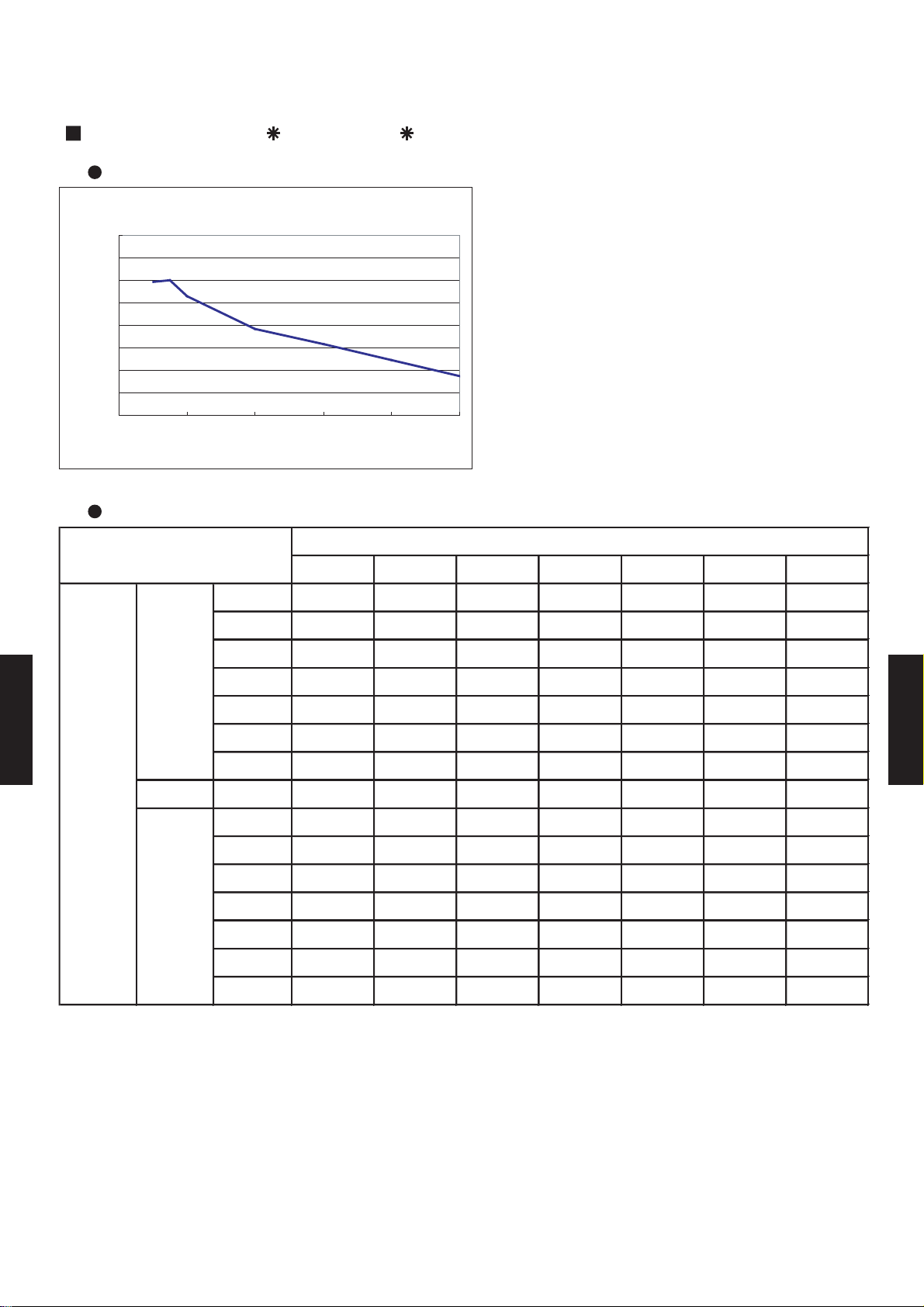
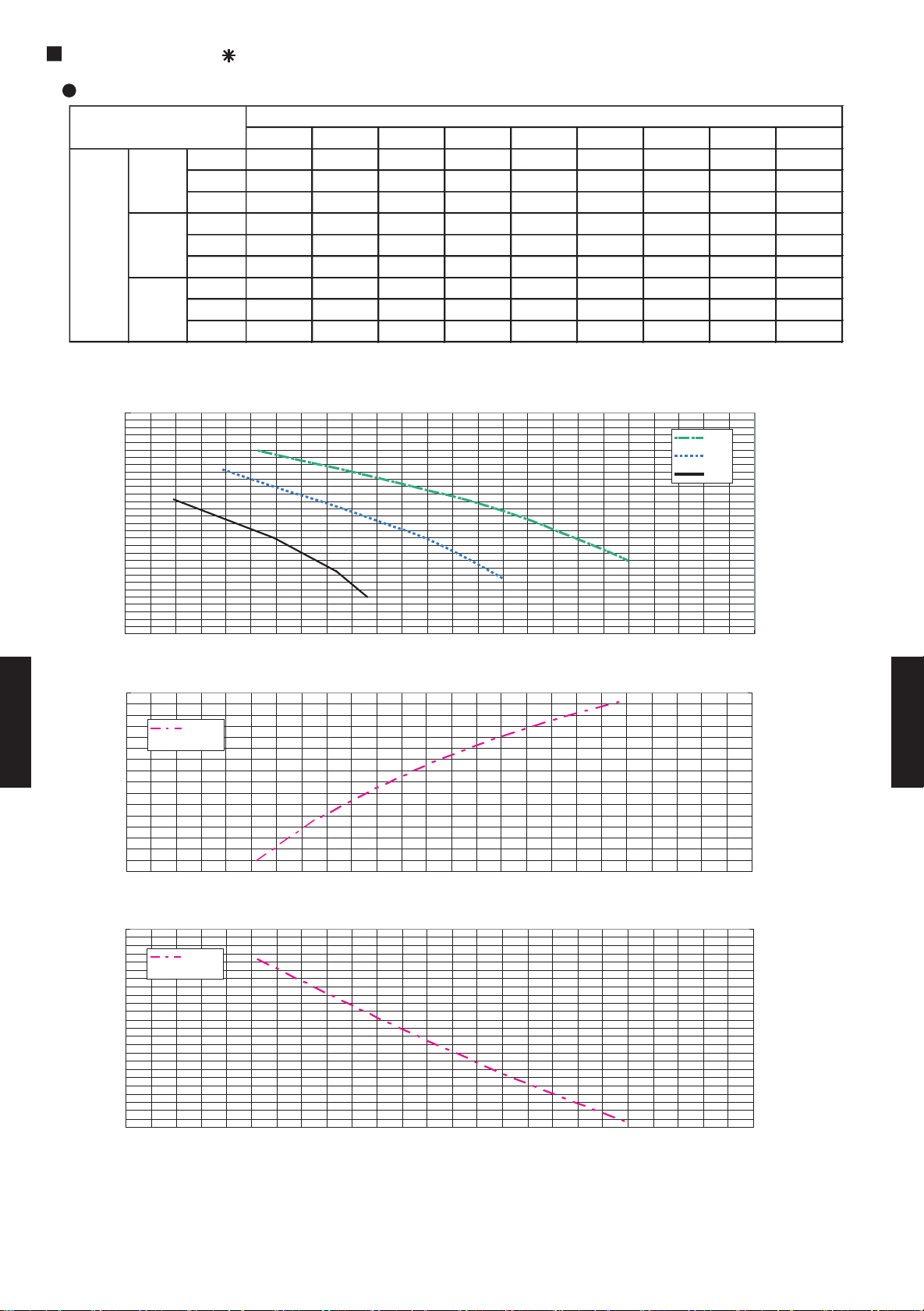
6-8.
0.700
0.750
0.800
0.850
0.900
0.950
1.000
1.050
1.100
0 10 20 30 40 50
COOLING
5 7.5 10 20 30 40 50
30 - - - - 0.857 0.823 0.788
25 - - - - 0.857 0.823 0.788
20 - - - 0.892 0.857 0.823 0.788
15 - - - 0.892 0.857 0.823 0.788
10 - - 0.964 0.892 0.857 0.823 0.788
7.5 - 1.000 0.964 0.892 0.857 0.823 0.788
5 0.997 1.000 0.964 0.892 0.857 0.823 0.788
0 0.997 1.000 0.964 0.892 0.857 0.823 0.788
-5 0.989 0.992 0.956 0.885 0.851 0.816 0.781
-7.5 - 0.988 0.953 0.882 0.847 0.813 0.778
-10 - - 0.949 0.878 0.844 0.809 0.775
-15 - - - 0.871 0.837 0.803 0.769
-20 - - - 0.864 0.830 0.796 0.763
-25 - - - - 0.823 0.790 0.756
-30 - - - - 0.816 0.783 0.750
PIPE LENGTH (m)
COOLING
Outdoor unit is
bottom-side
Outdoor unit is
up-side
HEIGHT DIFFERENCE (m)
CAPACITY COMPENSATION FOR PIPE LENGTH
AND HEIGHT DIFFERENCE
MODELS : AR 60F / AO 60F
Coefficient of compensation for pipe length
Coefficient of compensation
Pipe length (m)
Coefficient of compensation for height difference
DUCT TYPE
AR60
DUCT TYPE
AR60
- (06 - 14) -
Page 16

0.800
0.850
0.900
0.950
1.000
1.050
1.100
1.150
1.200
0 10 20 30 40 50
Coefficient of compensation
COOLING
0.800
0.850
0.900
0.950
1.000
1.050
1.100
1.150
1.200
0 10 20 30 40 50
HEATING
PIPE LENGTH (m)
HEATING
HEIGHT DIFFERENCE (m)
Outdoor unit is
bottom-side
Outdoor unit is
up-side
COOLING
HEIGHT DIFFERENCE (m)
Outdoor unit is
bottom-side
Outdoor unit is
up-side
PIPE LENGTH (m)
MODELS : AR 60U / AO 60U , ART60U / AOT60U
Coefficient of compensation for pipe length
Coefficient of conpensation for pipe length
Coefficient of compensation
Pipe length (m)
Coefficient of conpensation for pipe length
Pipe length (m)
Coefficient of compensation for height difference
5 7.5 10 20 30 40 50
30 - - - - 0.893 0.867 0.840
25 - - - - 0.893 0.867 0.840
20 - - - 0.919 0.893 0.867 0.840
15 - - - 0.919 0.893 0.867 0.840
10 - - 0.985 0.919 0.893 0.867 0.840
7.5 - 1.000 0.985 0.919 0.893 0.867 0.840
5 1.014 1.000 0.985 0.919 0.893 0.867 0.840
0 1.014 1.000 0.985 0.919 0.893 0.867 0.840
-5 1.005 0.992 0.977 0.912 0.886 0.860 0.834
-7.5 - 0.988 0.973 0.908 0.882 0.856 0.830
-10 - - 0.969 0.905 0.879 0.853 0.827
DUCT TYPE
AR60
-15 - - - 0.897 0.872 0.846 0.820
-20 - - - 0.890 0.864 0.839 0.814
-25 - - - - 0.857 0.832 0.807
-30 - - - - 0.850 0.825 0.800
DUCT TYPE
AR60
30 - - - - 0.917 0.901 0.884
25 - - - - 0.917 0.901 0.884
20 - - - 0.939 0.917 0.901 0.884
15 - - - 0.939 0.922 0.905 0.888
10 - - 0.979 0.944 0.927 0.910 0.893
7.5 - 0.993 0.982 0.946 0.929 0.912 0.895
5 1.005 0.995 0.984 0.948 0.931 0.914 0.897
0 1.010 1.000 0.989 0.953 0.936 0.919 0.902
-5 1.010 1.000 0.989 0.953 0.936 0.919 0.902
-7.5 - 1.000 0.989 0.953 0.936 0.919 0.902
-10 - - 0.989 0.953 0.936 0.919 0.902
-15 - - - 0.953 0.936 0.919 0.902
-20 - - - 0.953 0.936 0.919 0.902
-25 - - - - 0.936 0.919 0.902
-30 - - - - 0.936 0.919 0.902
5 7.5 10 20 30 40 50
- (06 - 15) -
Page 17
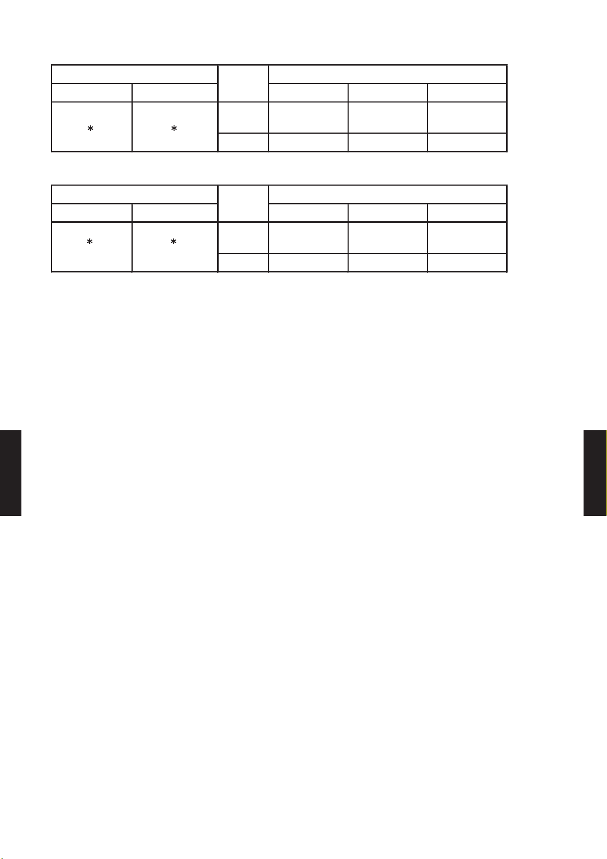
6-9. ADDITIONAL CHARGE CALCULATION
COOLING TYPE HEAT PUMP TYPE
AR 60F
m 7.5 7.5
3500 3700
3500 3700
3500+150 3700+200
3500+300 3700+400
3500+450 3700+600
3500+600 3700+800
3500+750 3700+1000
3500+900 3700+1200
30 40
TYPE
DUCTED MODEL
MODEL NAME
INDOOR
OUTDOOR
R410A
PIPE LENGTH
AMOUNT
30m
25m
g/m
ADDITIONAL CHARGE
20m
45m
50m (max)
g
40m
PRECHARGE
REFREGERANT TYPE
35m
MODELS : AR 60F / AO 60F
AR 60U / AO 60U , ART60U / AOT60U
REFRIGERANT CHARGE
AR 60U
ART60U
AO 60F
AO 60U
AOT60U
DUCT TYPE
AR60
- (06 - 16) -
DUCT TYPE
AR60
Page 18
6-10. OPERATION RANGE
Cooling
Dry
Heating - - -
Cooling
Dry
Heating 30 °C or less - -10 to 24 °C
Model Name
Operation Range
AR 60U
ART60U
AO 60U
AOT60U
Mode
Model Name
AO 60F
AR 60F
Operation Range
Mode
Indoor unit Outdoor unit Indoor unit Indoor humidity Outdoor unit
Indoor unit Outdoor unit Indoor unit Indoor humidity Outdoor unit
18 to 32 °C 80% or less 0 to 43 °C
18 to 32 °C 80% or less 0 to 43 °C
DUCT TYPE
AR60
DUCT TYPE
AR60
- (06 - 17) -
Page 19

6-11. FAN PERFORMANCE CURVE
50 75 100 125 150 175 200 225 250
m3/h
- - 3500 3315 3142 2932 2637 2339 2020.3
l/s - - 972 921 873 814 733 650 561
CFM - - 2060 1951 1849 1726 1552 1377 1189
m3/h
- 3000 2892 2727 2541 2336 2116 1883 -
l/s - 833 803 758 706 649 588 523 -
CFM - 1766 1702 1605 1495 1375 1245 1108 -
m3/h
2460 2494 2418 2319 2199 2057 - - -
l/s 683 693 672 644 611 571 - - -
CFM 1448 1468 1423 1365 1294 1211 - - -
230V
Static pressure (Pa)
FAN SPEED
Hi
Med
Low
6-11-1. NORMAL MODE
MODEL : AR 60F
230V
Q-h Characteristic curve
300
250
200
Hi
Med
Low
150
100
50
STATIC PRESSURE(Pa)
0
1,500 2,000 2,500 3,000 3,500 4,000
DUCT TYPE
AR60
102.0
100.0
98.0
96.0
94.0
92.0
90.0
88.0
Cooling capacity(%)
86.0
1,500 2,000 2,500 3,000 3,500 4,000
Air temp
Capacity
COOLING
15.5
15.0
14.5
14.0
13.5
13.0
12.5
12.0
11.5
DUCT TYPE
AR60
°C)
Air temperature(
AIR FLOW (m3/h)
Testcondition:NofilterandFanmode.
- (06 - 18) -
Page 20
MODEL : AR 60F
54 78 100 125 150 175 200 227 250
m3/h
- - 3564 3390 3193 2971 2689 2444 2092.4
l/s - - 990 942 887 825 747 679 581
CFM - - 2098 1995 1879 1748 1582 1439 1232
m3/h
- 3179 3027 2850 2660 2448 2208 1956 -
l/s - 883 841 792 739 680 613 543 -
CFM - 1871 1781 1677 1565 1441 1300 1151 -
m3/h
2630 2525 2415 2274 2113 1929 - - -
l/s 731 701 671 632 587 536 - - -
CFM 1548 1486 1422 1339 1244 1136 - - -
Static pressure (Pa)
240V
FAN SPEED
Hi
Med
Low
240V
300
250
200
150
Hi
Med
Low
Q-h Characteristic curve
100
50
0
1,500 2,000 2,500 3,000 3,500 4,000
COOLING
102.0
100.0
98.0
DUCT TYPE
AR60
96.0
94.0
92.0
90.0
88.0
Cooling capacity(%) STATIC PRESSURE(Pa)
86.0
1,500 2,000 2,500 3,000 3,500 4,000
Air temp
Capacity
AIR FLOW (m3/h)
15.5
15.0
14.5
14.0
13.5
13.0
12.5
12.0
11.5
°C)
DUCT TYPE
AR60
Air temperature(
Testcondition:NofilterandFanmode.
- (06 - 19) -
Page 21
MODELS : AR 60U, ART60U
50 75 100 125 150 175 200 225 250
m3/h
- - 3500 3315 3142 2932 2637 2339 2020.3
l/s - - 972 921 873 814 733 650 561
CFM - - 2060 1951 1849 1726 1552 1377 1189
m3/h
- 3000 2892 2727 2541 2336 2116 1883 -
l/s - 833 803 758 706 649 588 523 -
CFM - 1766 1702 1605 1495 1375 1245 1108 -
m3/h
2460 2494 2418 2319 2199 2057 - - -
l/s 683 693 672 644 611 571 - - -
CFM 1448 1468 1423 1365 1294 1211 - - -
230V
Static pressure (Pa)
FAN SPEED
Hi
Med
Low
230V
Q-h Characteristic curve
300
250
200
Hi
Med
Low
150
100
50
0
1,500 2,000 2,500 3,000 3,500 4,000
COOLING
102.0
100.0
98.0
96.0
DUCT TYPE
AR60
94.0
92.0
90.0
Cooling capacity(%) STATIC PRESSURE(Pa)Heating capacity(%)
88.0
86.0
1,500 2,000 2,500 3,000 3,500 4,000
Air temp
Capacity
15.0
14.5
14.0
13.5
13.0
12.5
12.0
11.5
11.0
°C)
DUCT TYPE
AR60
Air temperature(
HEATING
104.0
102.0
100.0
98.0
96.0
94.0
92.0
90.0
88.0
86.0
84.0
82.0
80.0
1,500 2,000 2,500 3,000 3,500 4,000
Air temp
Capacity
AIR FLOW (m3/h)
44.0
43.0
42.0
41.0
40.0
39.0
38.0
37.0
36.0
°C)
Air temperature(
Testcondition:NofilterandFanmode.
- (06 - 20) -
Page 22

MODELS : AR 60U, ART60U
54 78 100 125 150 175 200 227 250
m3/h
- - 3564 3390 3193 2971 2689 2444 2092.4
l/s - - 990 942 887 825 747 679 581
CFM - - 2098 1995 1879 1748 1582 1439 1232
m3/h
- 3179 3027 2850 2660 2448 2208 1956 -
l/s - 883 841 792 739 680 613 543 -
CFM - 1871 1781 1677 1565 1441 1300 1151 -
m3/h
2630 2525 2415 2274 2113 1929 - - -
l/s 731 701 671 632 587 536 - - -
CFM 1548 1486 1422 1339 1244 1136 - - -
240V
FAN SPEED
Hi
Med
Low
Static pressure (Pa)
240V
Q-h Characteristic curve
300
250
200
Hi
Med
Low
150
100
50
0
1,500 2,000 2,500 3,000 3,500 4,000
COOLING
102.0
100.0
98.0
DUCT TYPE
AR60
96.0
94.0
92.0
90.0
Cooling capacity(%) STATIC PRESSURE(Pa)Heating capacity(%)
88.0
86.0
1,500 2,000 2,500 3,000 3,500 4,000
Air temp
Capacity
15.0
14.5
14.0
13.5
13.0
12.5
12.0
11.5
11.0
°C)
DUCT TYPE
AR60
Air temperature(
HEATING
104.0
102.0
100.0
98.0
96.0
94.0
92.0
90.0
88.0
86.0
84.0
82.0
80.0
1,500 2,000 2,500 3,000 3,500 4,000
Air temp
Capacity
AIR FLOW (m3/h)
44.0
43.0
42.0
41.0
40.0
39.0
38.0
37.0
36.0
°C)
Air temperature(
Testcondition:NofilterandFanmode.
- (06 - 21) -
Page 23

6-12. NOISE LEVEL CURVE
NC-20
NC-40
NC-50
NC-60
NC-30
NC-15
NC-25
NC-35
NC-45
NC-55
NC-65
NC-20
NC-40
NC-50
NC-60
NC-30
NC-15
NC-25
NC-35
NC-45
NC-55
NC-65
6-12-1. COOLING
OUTDOOR UNIT
Condition
Voltage : 400-415V / 50Hz
MODEL : AO 60F
80
70
60
50
40
30
Octave band sound pressure level, dB:(0dB=0.0002µbar)
20
MODELS : AO 60U, AOT60U
80
70
60
50
40
30
Octave band sound pressure level, dB:(0dB=0.0002µbar)
20
10
0
DUCT TYPE
AR60
63 125 250 500 1,000 2,000 4,000 8,000
Octave band center frequency,Hz Octave band center frequency,Hz
10
0
63 125 250 500 1,000 2,000 4,000 8,000
DUCT TYPE
AR60
- (06 - 22) -
Page 24

NC-20
NC-40
NC-50
NC-60
NC-30
NC-15
NC-25
NC-35
NC-45
NC-55
NC-65
NC-20
NC-40
NC-50
NC-60
NC-30
NC-15
NC-25
NC-35
NC-45
NC-55
NC-65
INDOOR UNIT
Condition
Fan speed : High
Voltage : 230-240V / 50Hz
Static pressure : 100Pa
MODEL : AR 60F
80
70
60
50
40
30
Octave band sound pressure level, dB:(0dB=0.0002µbar)
20
MODELS : AR 60U, ART60U
80
70
60
50
40
30
Octave band sound pressure level, dB:(0dB=0.0002µbar)
20
10
0
DUCT TYPE
AR60
63 125 250 500 1,000 2,000 4,000 8,000
Octave band center frequency,Hz Octave band center frequency,Hz
10
0
63 125 250 500 1,000 2,000 4,000 8,000
DUCT TYPE
AR60
- (06 - 23) -
Page 25

NC-20
NC-40
NC-50
NC-60
NC-30
NC-15
NC-25
NC-35
NC-45
NC-55
NC-65
NC-20
NC-40
NC-50
NC-60
NC-30
NC-15
NC-25
NC-35
NC-45
NC-55
NC-65
6-12-2. HEATING
OUTDOOR UNIT INDOOR UNIT
MODELS : AO 60U, AOT60U
Condition
Voltage : 400-415V / 50Hz
80
70
60
50
40
30
MODELS : AR 60U, ART60U
Condition
Fan speed : High
Voltage : 230-240V / 50Hz
Static pressure : 100Pa
80
70
60
50
40
30
Octave band sound pressure level, dB:(0dB=0.0002µbar)
20
10
DUCT TYPE
AR60
0
63 125 250 500 1,000 2,000 4,000 8,000
Octave band center frequency,Hz
Octave band sound pressure level, dB:(0dB=0.0002µbar)
20
10
DUCT TYPE
0
63 125 250 500 1,000 2,000 4,000 8,000
Octave band center frequency,Hz
AR60
- (06 - 24) -
Page 26

SOUND LEVEL CHECK POINT
OUTDOOR UNIT
INDOOR UNIT
DUCT TYPE
AR60
DUCT TYPE
AR60
- (06 - 25) -
Page 27
6-13. ELECTRIC CHARACTERISTICS
Main Fuse (Circuit breaker)
Current
mm
2
Model Name
0.7 x 2
34(240V)
3N 400
50
33 20
0.7
3.5
0.14 x 2
0.14 x 2
0.14 x 2
ART60U
AOT60U
20
4.0 2.5
3N 415
0.7 x 2
0.7 x 2
0.7
0.7
3.5
3.5
*1) Wiring Spec
Max Operating Current
Starting Current
Outdoor Fan Motor
Indoor Fan Motor
20
20
33 20
33 20
4.0 2.5
4.0 2.5
34(240V)
34(240V)
AR 60F
AR 60U
AO 60F
AO 60U
Mode
Rated Value
Power Supply
MODELS : AR 60F / AO 60F
AR 60U / AO 60U , ART60U / AOT60U
Indoor unit
Outdoor unit
Voltage V
Freqency Hz
Cooling Heating Cooling Heating Cooling Heating
Current A 10.0 - 10.2 9.8 10.9 10.6
Input kW 5.93 - 6.06 5.54 6.20 5.75
A 14.4 - 14.4 13.4 14.4 13.4
A 70 - 70 70 70 70
A
Power Cable
*2)Limited wiring length m
Input kW
Full Load Amp. A
Input kW
Full Load Amp. A
Belt heater W
*1) Wiring Spec : Selected Sample
(Selected based on Japan Electrotechnical Standard and Codes Committee E0005)
*2) Limited Wiring length : This is the wiring length in case voltage descent is less than 2%.
When the wiring length becomes long, please select the wiring of a more larger diameter.
DUCT TYPE
AR60
DUCT TYPE
AR60
- (06 - 26) -
Page 28

6-14. SAFETY DEVICE
MODEL NAME
PROTECTION FORM
AO 60F
AO 60U
AOT60U
FUSE (SIDE OF POWER SUPPLY TERMINAL)
- 10A 250V 10A 250V
FUSE ON MAIN PCB - - 6.3A 250V
FUSE ON POWER PCB - - -
FAN MOTOR PROTECTOR THERMAL PROTECTOR
150
°C±5°C
OFF 150
°C±5°C
OFF
COMPRESSOR -
165
°C±5°C
OFF 165
°C±5°C
OFF
HIGH PRESSURE PROTECTION - AC250V 4.2MPa DC5V 4.2MPa
MODEL NAME
PROTECTION FORM
PCB FUSE - 3.15A 250V 3.15A 250V
FAN MOTOR PROTECTOR THERMAL PROTECTOR
150
°C±5°C
OFF 150
°C±5°C
OFF
FUSE FOR FAN MOTOR - 10A 250V 10A 250V
OUTDOOR UNIT
INDOOR UNIT
AR 60F
DUCT TYPE
AR60
AR 60U
ART60U
DUCT TYPE
AR60
- (06 - 27) -
Page 29
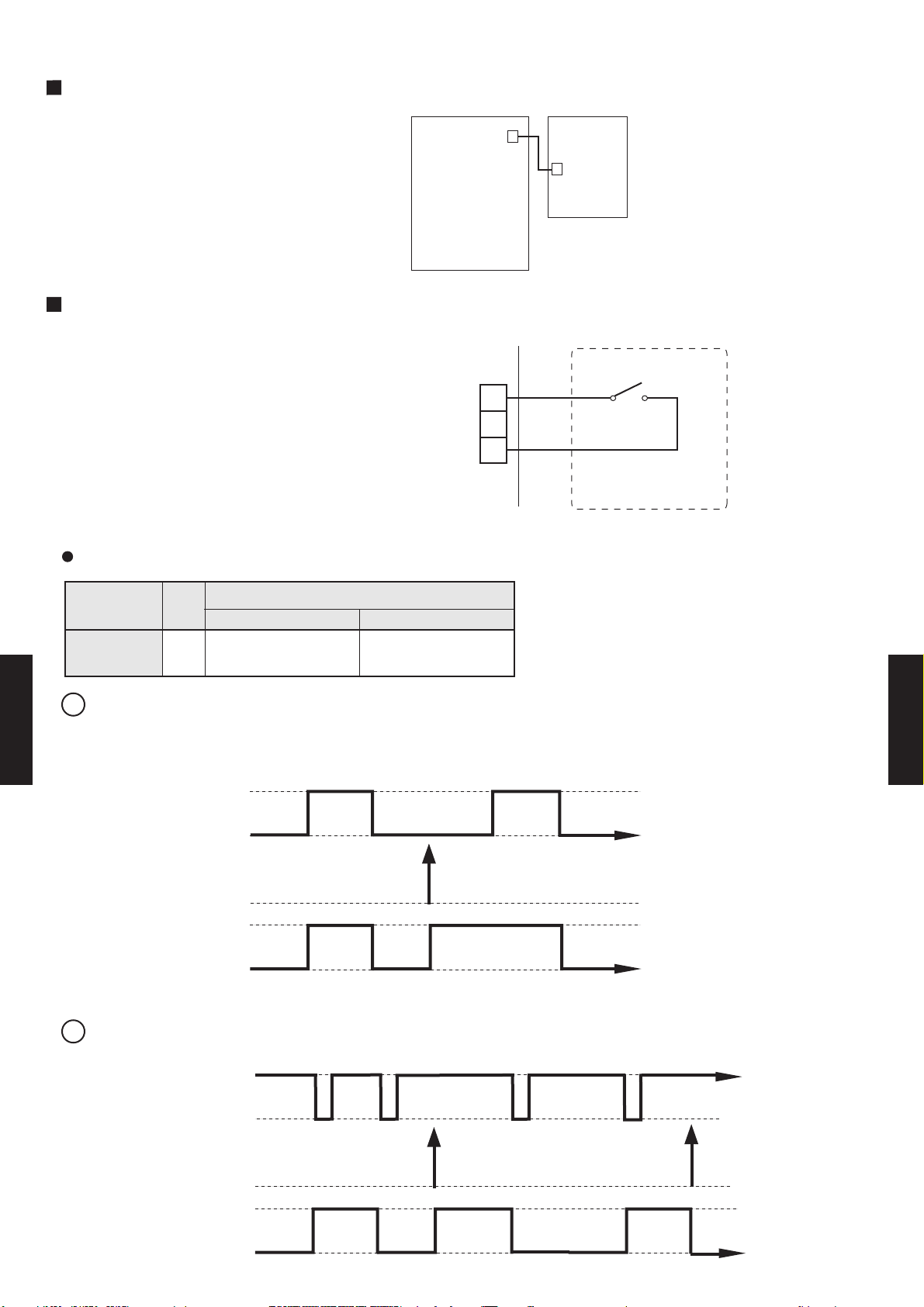
6-15. EXTERNAL INPUT & OUTPUT
PREP
ARA
TION
When the external input / output is used,
connect the external signal wire as shown
in the figure below.
CONTROL
INPUT
You can control air conditioner on/off by
external control. You can select either
Edge and Pulse.
CN106
(Black)
Indoor unit
PCB
[Example]
+
Indoor
unit
-
CN114
(White)
CN5
(Black)
PCB
Ch1
1
2
3
Field supply
DIP Switch (Indoor Unit)
SW state
ON
PulseEdge
SW2
DIP-Switch
NO.
OFF
2
1 Edge
1.The last command has priority.
2.The wire connection is separate from the power cable line.
DUCT TYPE
AR60
Ch1
On
(Input)
Off
Remote
controller
Indoor
Operation
On
unit
Stop
DUCT TYPE
AR60
2 Pulse
Ch1
(Input)
Remote
controller
Indoor
unit
Operation
Stop
200ms 200ms 200ms
On
- (06 - 28) -
Off
Page 30

OPERA
[Example]
TION DISPLA
Y
Operation
indicator
Field supply
Operation
Ic
Vc : DC20V
Ic : 10mA
Vc
or
or less
or less
Indoor
unit
CN115
(WHITE)
+
2
1
-
Indoor
unit
Stop
SHORT
CN115
FRESH
(Output)
AIR OUTPUT SETTING
OPEN
You can control sub fan by synchronizaton with fan operation of indoor unit.
[Example]
Fuse
Indoor
unit
+
1
2
-
CN14
(GREEN)
DUCT TYPE
AR60
Indoor
Field supplied
Operation
unit fan
Stop
14V
CN14
(Output)
0V
Power
Fan, other
DUCT TYPE
AR60
- (06 - 29) -
Page 31
EXTERNAL
ELECTRICAL HEA
TER OUTPUT SETTING
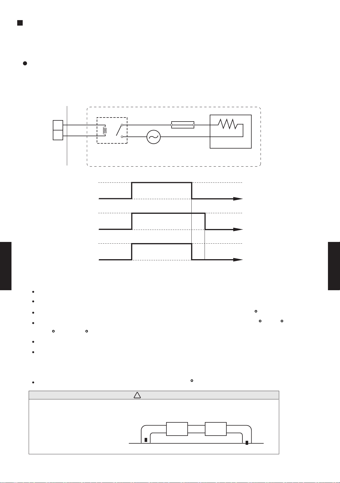
You can control Electrical heater (Booster) by sychronization with heating operation.
When temperature is -10 to -3 degrees from Setpoint,External electrical heater is ON.
When temperature is -1 degrees from Setpoint,External electrical heater Stops.
Jumper wire (Indoor Unit)
This is used to continue indoor unit fan operation for 1 minute after thermo OFF in heating mode.
1 minute delay control set by cutting JM3 on PCB.
[Example]
Fuse
Indoor
unit
+
1
2
-
CN15
(ORANGE)
Indoor
Operation
Field supplied
unit
Heating
Indoor
Stop
Operation
unit fan
Stop
14V
CN15
(Output)
0V
<Operation condition>
DUCT TYPE
AR60
All conditions shall be met.
Under heating operation.
Fan mode : Either Hi, Med, Low, Quiet.
Power
External Heater, other.
1min
DUCT TYPE
AR60
Cold air prevention function not working (Heat exchanger temperature over 27 C ).
Temperature subtracted set temperature from room temperature is between -10 C to -3 C.
-10 C < *T < -3 C *T=Room temperature
Compressor 3 minutes stop mode is released.
Defrosting mode is released.
<Release condition>
Do not meet above condition , or room temperature is 1 C below from set temperature.
CAUTION!
!
Please locate external a heater between the indoor unit and the ductwork.
Please be sure to use delay control of a fan.
External
Heater
Supply air
Indoor unit
Return air
- (06 - 30) -
Page 32
1
2
3
4
1 Room temperature correct coefficient of heating
2 External input select
3 Auto restart validity/invalidity
Rotary SW SW 3 Indoor unit number setting
JM1 Room temperature correct coefficient of cooling
JM2 Commercial mode setting
JM3 Fan delay setting
Jumper Wire
Forbidden
INDOOR UNIT
DIP SW
SW 1
SW 2
6-16. FUNCTION SETTING
6-16-1. INDOOR UNIT
SWITCH POSITION
Duct type Indoor unit control circuit board
POWER PCB
CN114
CN106
CN115
DUCT TYPE
AR60
MAIN PCB
ON
OFF
CN4
CN5
CN16
CN14
CN15
SW1 SW2
1 2 3 1 2 34
SW1 SW2
SW3
ON
OFF
JM1
JM2
JM3
DUCT TYPE
AR60
CN16
- (06 - 31) -
Page 33

6-16-2. SWITCH FUNCTION (INDOOR UNIT)
SW1-1 OFF
SW1-2 OFF
SW1-3 OFF
SW1-4 OFF
SW2-1 SW state
OFF +4 deg (Ceiling setting)
ON 0 deg (Room setting)
SW2-2 SW state
OFF Edge
ON Pulse
SW2-3 SW state
OFF Validity
ON Invalidity
SW3 SW state
0 single
1-15 Indoor unit address
DIP SWITCH SETTING
1. SW1 setting
1-1 Dip SW 1-1,1-2,1-3,1-4 setting forbidden
( Factory setting)
2. SW2 setting
2-1 Room temperature correct coefficient of heating.
Decide the heating temperature correct coefficient vale of heating.
Heat temperature corrction
( Factory setting)
2-2 Control input setting
This switch is used to select the format of external input command as shown in the table below.
( Factory setting)
DUCT TYPE
AR60
2-3 Auto restart setting
DUCT TYPE
AR60
Auto restart function can be selected by turning this switch ON/OFF.
( Factory setting)
ROTARY SWITCH SETTING
This switch can be used when group control system. Set the indoor unit address in the 1,2,-,15 order.
( Factory setting)
- (06 - 32) -
Page 34
JUMPER WIRE SETTING
Connector INPUT OUTPUT REMARKS
CN114
CONTROL INPUT
(OPERATION/STOP)
-
CN115 - OPERATION DISPLAY
CN14 - FRESH AIR
CN15 - ELECTRICAL HEATER
See external
input/output settings
for details.
JM2 JM state
Connect Residencial
Disconnect Commercial
JM3 JM state
Connect Invalidity
Disconnect Validity
JM1 JM state
Connect 0 deg
Disconnect + 2 deg
Room temperature correct coefficient of cooling.
Decide the cooling temperature correct coefficient value of cooling.
Cool temperature corrction
( Factory setting)
Commercial mode setting
"Hot start" can be canceled,fan operates continously when indoor unit is ON on every mode.
When you select "FAN:AUTO"mode fan goes in "HIGH"
( Factory setting)
Fan delay setting
This setting can be used when the auxiliary heater is mounted.
When the fan operation is stopped when the indoor unit is operating
with an auxiliary heater,the fan operation continues one minutes.
( Factory setting)
EXTERNAL INPUT AND OUTPUT
DUCT TYPE
AR60
- (06 - 33) -
DUCT TYPE
AR60
Page 35
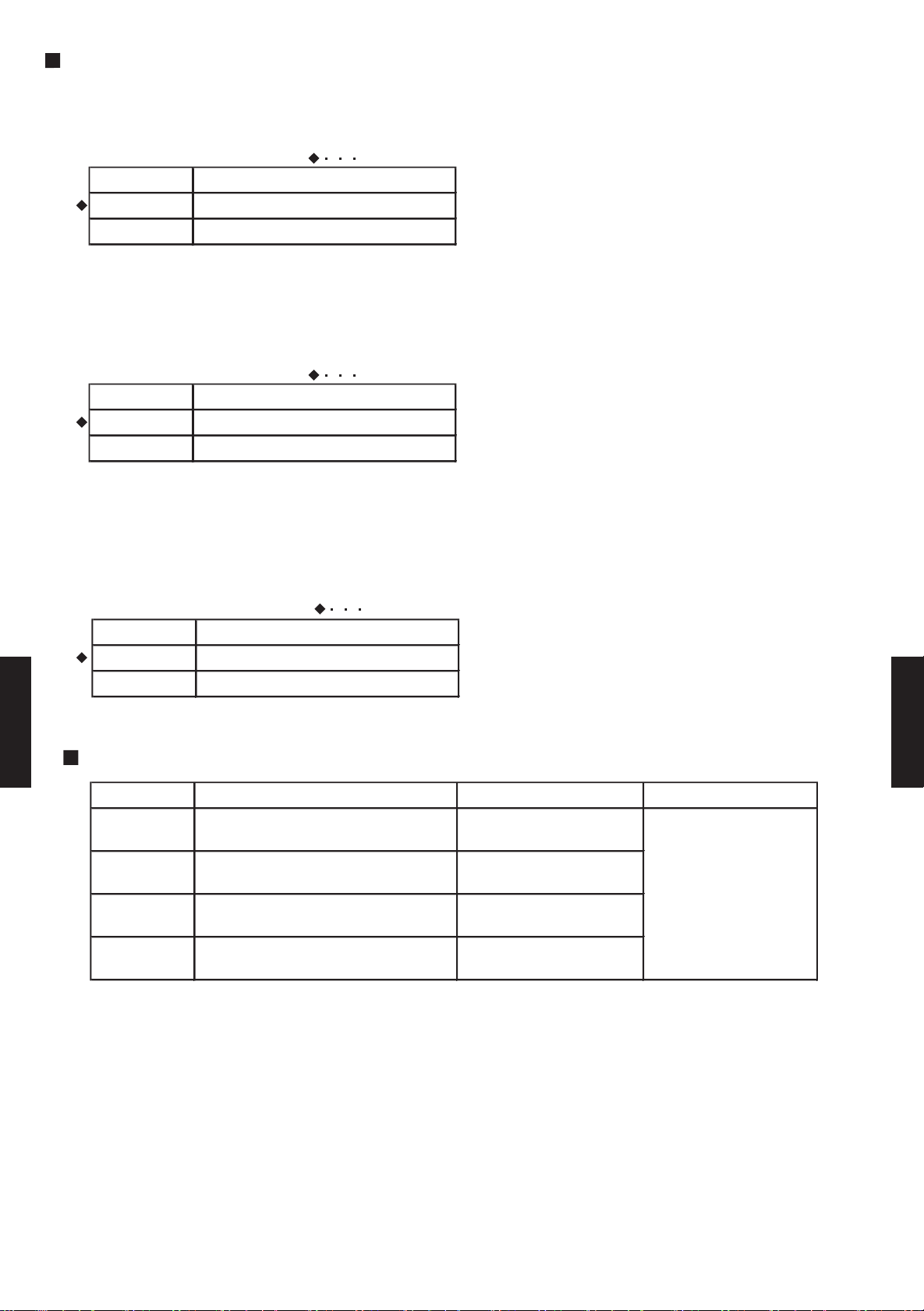
6-16-3. WIRED, SIMPLE REMOTE CONTROLLER CIRCUIT BOARD
Wired,Simple remote controller
1
Dual remote controller setting
2
Group control setting
DIP SW
SWITCH POSITION
Wired remote controller
Front case (back side)
3
4
Model setting
Auto changeover setting
5
6
Memory backup setting
OFF
ON
1
2
3
4
5
6
ON
DIP Switch
Simple remote controller
DUCT TYPE
AR60
DUCT TYPE
AR60
ON
ON
OFF
12345
6
DIP switches
- (06 - 34) -
Page 36

6-16-4. WIRED, SIMPLE REMOTE CONTROLLER
DIP SWITCH SETTING
1. SW setting
1-1 Dual remote controller setting
Set the remote controller DIP switch No.1 and 2 according to the following table.
( Factory setting)
Number of
remote
controller
1 (Normal)
2 (Dual)
1-2 Group control setting
Number of indoor unit connection (One/Multiple)
This is switched according to the number of connected indoor units.
DIP-SW
No.3
OFF
Master unit Slave unit
DIP-SW
No.1
OFF
DIP-SW
No.2
ON
( Factory setting)
Number of indoor unit
One unit connection
OFF
OFF
DIP-SW
No.1
ON ON
DIP-SW
No.2
ON Multiple unit connection
1-3 Model setting
The system type of the outdoor unit can be selected by setting up DIP switch No.4 as follows.
( Factory setting)
DIP-SW
No.4
OFF
DUCT TYPE
AR60
ON Cooling only model
Heat Pump model
Model
DUCT TYPE
AR60
1-4 Auto changeover setting
Selecting auto changeover validity / invalidity.
( Factory setting)
DIP-SW
No.5
OFF
ON Validity
Auto changeover
Invalidity
1-5 Memory backup setting
Set to ON to use batteries for the memory backup.if batteries are not used,
all of the settings stored in memory will be deleted if there is a power failure.
This function is wired remotecontroll only.
( Factory setting)
DIP-SW
No.6
OFF
ON Validity
Memory backup
Invalidity
- (06 - 35) -
Page 37

6-17. OPTIONAL PARTS
SIMPLE REMOTE CONTROLLERS
UTB - YPB : FUJITSU BRAND
UTB - GPB : GENERAL BRAND
Remote controller which gives priority to ease-of-use and allows operation
of the necessary functions only.
REMOTE SENSOR UNIT
UTD - RS100
Accurate and Comfortable
New amenity space can be offered by installing the thermo sensor in the remote controller.
Because the remote controller has the switching function, the user can select the position of the
sensor. (Room temperature sensor selection)
Remote Sensor
in the bed room (effective at night)
Simple remote
controllers
Example of room temperature
sensor selection
Sensor part
DUCT TYPE
AR60
Remote Controller
in the living room (effective during the day)
THERMO
Day
Wired Remote Controller
The detecting point can be freely changed.
SENSOR
Night
Remote Sensor (Optional Parts)
DUCT TYPE
AR60
- (06 - 36) -
 Loading...