

Page 1
SPLIT TYPE AIR
Indoor unitModels
Outdoor unit
CONDITIONER (50Hz)
DUCT
type
ARG60AUAK
ARG60RUAK
AOG60APAGT
AOG60RPAGT
CONTENTS
SPECIFICATIONS
OUTLINE AND DIMENSIONS
REFRIGERANT SYSTEM DIAGRAM
CIRCUIT DIAGRAM
PCB CIRCUIT DIAGRAM
DIP SWITCH SETTING
ERROR CONTENTS
DISASSEMBLY ILLUSTRATION
PARTS LIST
STANDARD ACCESSORIES
1
2
4
5
7
10
11
12
19
22
Page 2
SPECIFICATIONS
TYPE Cooling Colling & Heating
INDOOR UNIT
OUTDOOR UNIT
COOLING CAPACITY (kW)
HEATING CAPACITY (kW)
ELECTRICAL SPECIFICATIONS
POWER SUPPLY (V)
FREQUENCY (Hz)
RUNNING
CURRENT
INPUT (kW)
(kW/kW)
EER
MOISTURE REMOVAL
AIR CIRCULATION - Hi (m
(A)
COOLIING
HEATING
COOLIING
HEATING
COOLIING
HEATING
( /hr )
3
COMPRESSOR
TYPE
/hr )
ARG60AUAK
AOG60APAGT
16.4 - 17.0
-----
380 - 415
50
9.8 - 9.8
-----
5.80 - 5.90
-----
2.83 - 2.88
-----
6.5
3,600
Hermetic type, 2 poles,
3-phase, Induction motor, Scroll
ARG60RUAK
AOG60RPAGT
16.4 - 17.0
17.8 - 18.2
9.8 - 9.8
8.7 - 8.7
5.90 - 6.00
5.05 - 5.25
2.78 - 2.83
3.52 - 3.47
DISCRIMINATION
REFRIGERANT R-22
FAN MOTOR
POWER SUPPLY (V)
DISCRIMINATION
INDOOR UNIT
OUTDOOR UNIT
HI-SPEED ( r.p.m. )
MED-SPEED ( r.p.m. )
LO-SPEED ( r.p.m. )
DISCRIMINATION
HI-SPEED ( r.p.m. )
DIMENSIONS
INDOOR UNIT
OUTDOOR UNIT
INDOOR UNIT
OUTDOOR UNIT
H x W x D (mm)
H x W x D (mm)
NET / GROSS (kg)
NET / GROSS (kg)
REFRIGERANT CHARGE (R-22)
PIPE LENGTH
Full Charge Amount
Additional Charge
Chargeless
MAX PIPE LENGTH
MAX ELEVATION
7.5 m
10.0m
20.0 m
30.0 m
40.0 m
50.0 m
( g )
ZR72KC-TFD
3,800 4,800
240
MFA-60NTFS
1,300
1,135
960
MFB-362FT
800
400 x 1,050 x 500
1,355 x 940 x 370
50 / 55
121 / 136 129 / 144
3,800 g 4,800 g
3,900 g 4,800 g
4,300 g 4,800 g
4,700 g 5,400 g
5,100 g 6,000 g
5,500 g 6,600 g
40 g / m
7.5 m
50 m
30 m
60 g / m
20 m
50 m
30 m
2004.06.30 1
Page 3
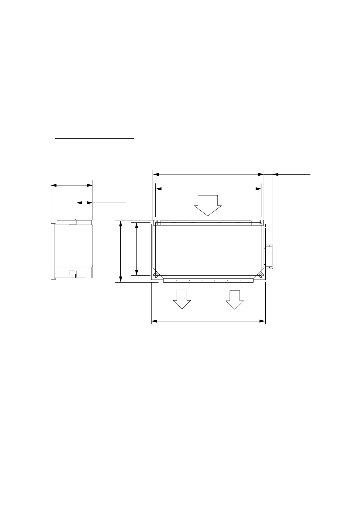
OUTLINE AND DIMENSIONS
(Unit : mm)
INDOOR UNIT
Models : ARG60AUAK
ARG60RUAK
395 mm
155 mm
585 mm
500 mm
1,050 mm
1,000 mm
AIR
1,080 mm
85 mm
AIR
AIR
2004.06.30 2
Page 4
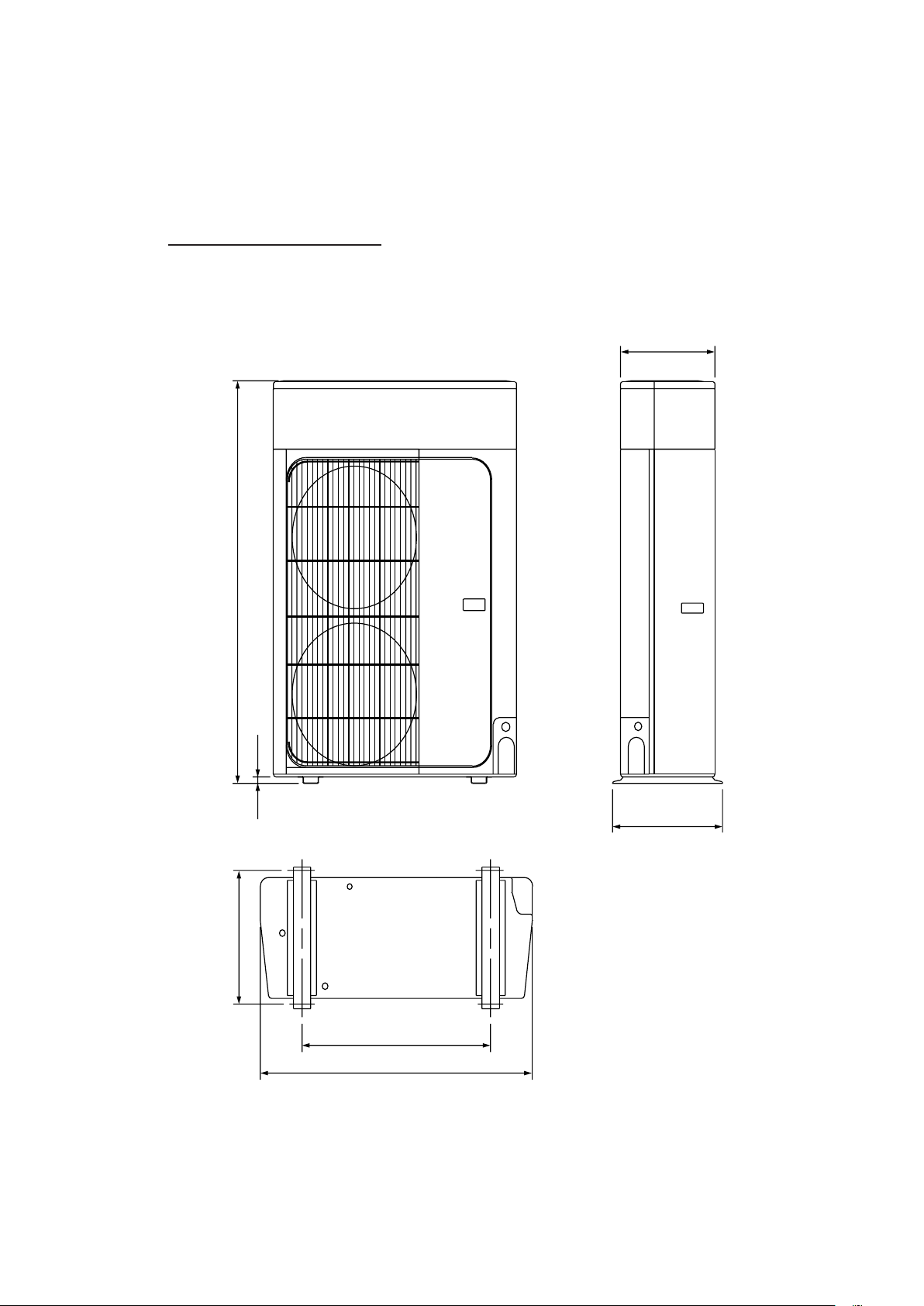
OUTDOOR UNIT
Models : AOG60APAGT
AOG60RPAGT
(Unit : mm)
370
1,355
23
425
400
650
940
2004.06.30 3
Page 5
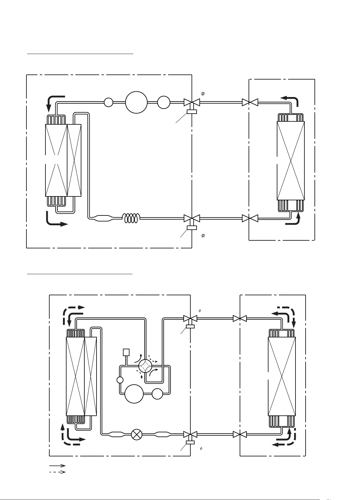
REFRIGERANT SYSTEM DIAGRAM
Model : ARG60AUAK / AOG60APAGT
OUTDOOR UNIT
CONDENSER
MUFFLER
DRYER
ACCUMULATOR
COMPRESSOR
Charging valve
CAPILLARY TUBE
Charging valve
INDOOR UNIT
Refrigerant pipe
19.05mm(3/4")
EVAPORATOR
Refrigerant pipe
9.52mm(3/8")
Model : ARG60RUAK / AOG60RPAGT
OUTDOOR UNIT
HIGH
PRESSURE
SWITCH
4-Way
valve
CONDENSER
MUFFLER
COMPRESSOR
DRYER
EXPANSION
VALVE
ACCUMULATOR
Charging
valve
ACCUMULATOR
STR AINER
Charging valve
INDOOR UNIT
Refrigerant pipe
19.05mm(3/4")
EVAPORATOR
Refrigerant pipe
9.53mm(3/8")
:
COOL
:
HEAT
2004.08.10 4
Page 6
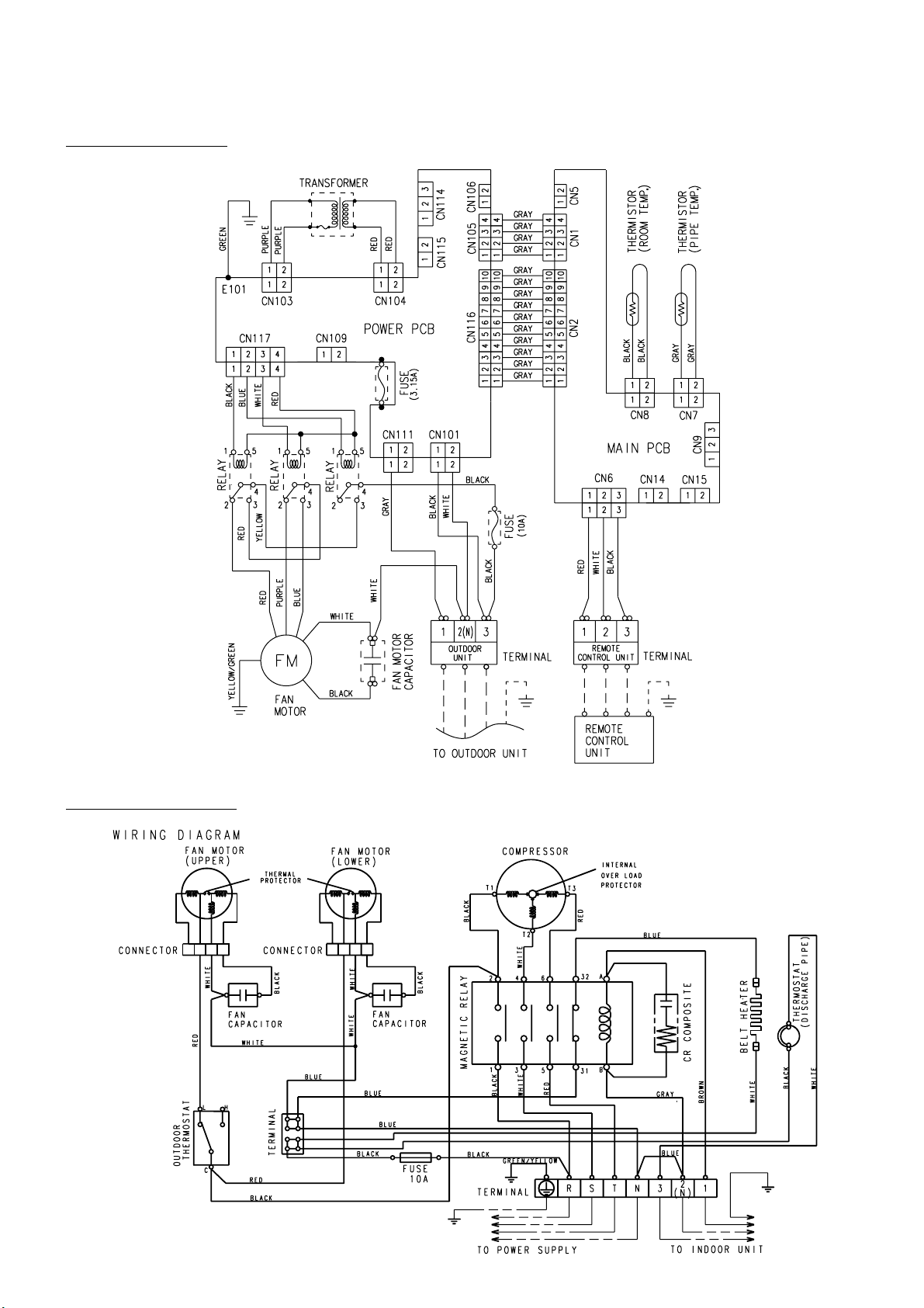
CIRCUIT DIAGRAM
Model : ARG60AUAK
Model : AOG60APAGT
2004.06.30 5
Page 7
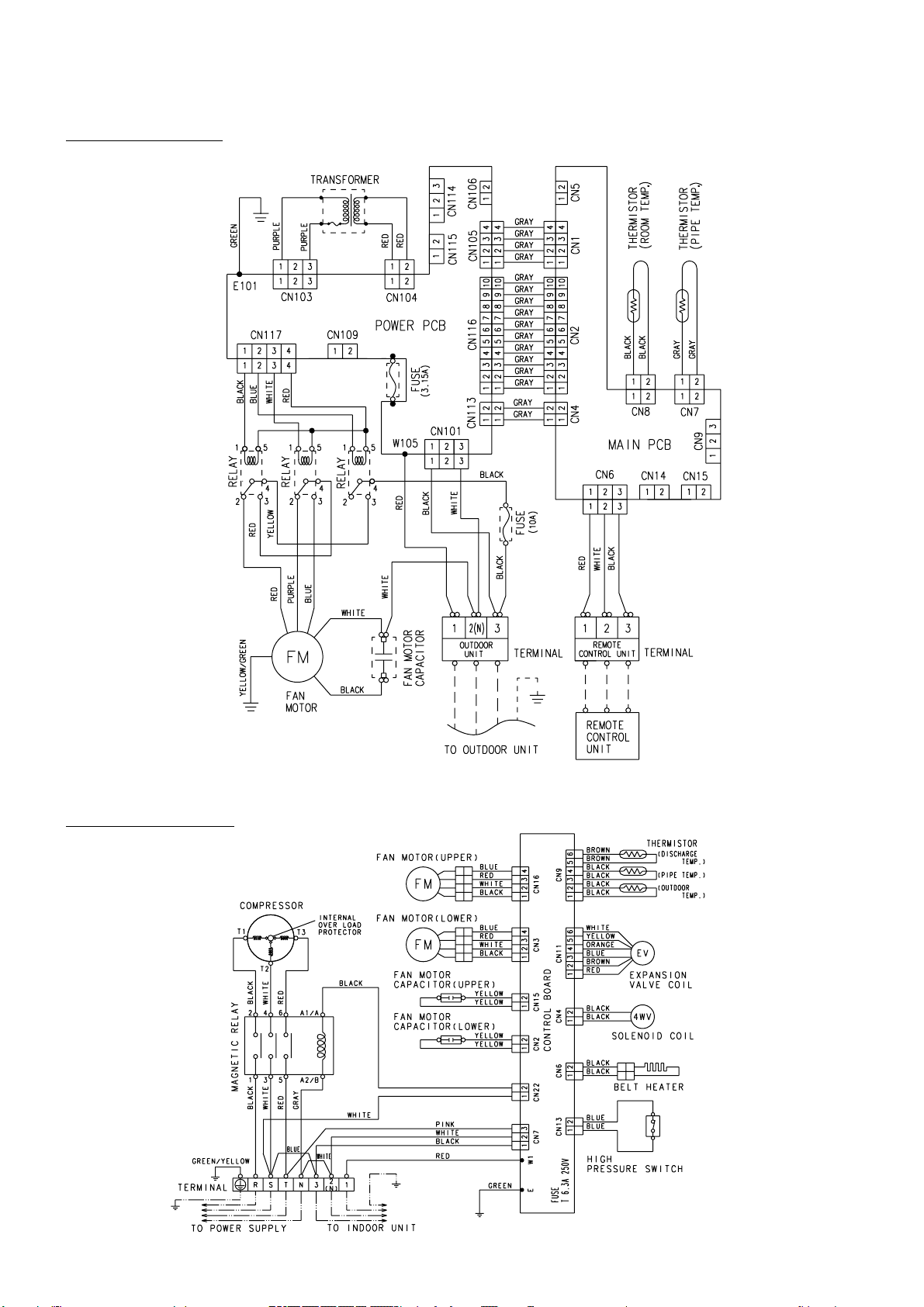
Model : ARG60RUAK
Model : AOG60RPAGT
2004.06.30 6
Page 8
I N D O O R P R I N T E D C I R C U I T B O A R D
C I R C U I T D I A G R A M
Model : ARG60AUAK
CONTROLLER PCB ASSEMBLY ( MAIN PCB )
EZ-00304WSE-C
R18 - R20
1.0K <1/10W> x 3
C21 - C23
0.1 <F> x 3
R7 - R10
1.0K <1/10W> x 4
FAN CHANGER
FAN CHANGER
C17 - C20
0.1 <F> x 4
C35
0.01
<B>
16 1
I C3 (1/7)
uPA2003GR
I C2 (1/7)
uPA2003GR
R56 1.0K
<1/10W>
C38
0.01
<F>
I C9 (4/7)
uPA2003GR
15
13
6
4
2
R77 10K
<1/10W>
1
Q2
DTC124EKA
C26
0.1
<F>
2
8
10 7
5V
R53
10K
<1/10W>
14V
9
14
2
16 1
4
R78 390
<1/10W>
3
2
I C3 (1/7)
uPA2003GR
512
C27
0.1
<F>
C32
0.01
<F>
C34
0.01
<F>
14V
3
1
5V
C25
0.1
<F>
9
3
Q101
2SD1932
D102
MTZJ15C
C114
0.01
<B>
1
2
FL102
BL02RN1
R108 330
<1/4W>
C113
0.01
<B>
FAN ON/OFF
RED
UL1430 AWG24
B5P-SHF-1AA
WHITE
CN105
B04B-PASK-1
WHITE
14V
+
K108
K104
FAN H/M
FAN M/L
14V
I NT
TEST
SW3
5
C 1
C109
10/
25V
FL101
BL02RN1
14V
1
2
3
4
5
6
7
8
9
10
R25
8
4
4
3
2
2
1
1
2
PC103
TLP621
<GB>
CN3
5V
DC SUPPLY
UL1430 AWG26 GRAY
1
UL1430 AWG26 GRAY
2
3
UL1430 AWG26 GRAY
UL1430 AWG26 GRAY
4
CN114
B3B-XH-AM
WHITE
CN1
B04B-PASK-1
WHITE
1
2
3
5V
R107 330
1
<1/4W>
2
4
3
1
2
RELAY DRIVE
UL1430 AWG26 GRAY
UL1430 AWG26 GRAY
UL1430 AWG26 GRAY
UL1430 AWG26 GRAY
UL1430 AWG26 GRAY
UL1430 AWG26 GRAY
UL1430 AWG26 GRAY
UL1430 AWG26 GRAY
UL1430 AWG26 GRAY
UL1430 AWG26 GRAY
CN116
B10B-PASK-1
WHITE
5V
10K <1/10W> x 4
R29 R30
1
2
3
4
5
10K <1/10W> x 4
R26
R27
R28
EX. I N
EX. OUT
CN115
B2B-XH-AM
WHITE
CN106
B02B-PAKK-1
BLACK
EX. SIGNAL
CN4
B02B-PARK-1
RED
CN16
B02B-PASK-1
WHITE
NEW SERIAL
R31 R32
R21 1.0K <1/10W>
R22 1.0K <1/10W>
R23 1.0K <1/10W>
R24 1.0K <1/10W>
14V
12V
1
2
3
4
C42 - C43
0.1 <F> x 2
SW1
8
7
6
5 1
5V
+
CN5
B02B
-PAKK-1
BLACK
EX. SIGNAL
SERIAL
1
2
3
4
5
6
7
8
9
10
CN2
B10B-PASK-1
WHITE
14V
5V
6 3
5
4
C4
0.1 <F>
4
3
REMOTE CUSTOM
2
REMOTE CUSTOM
C1
100/6.3V
1
2
R76 10K
<1/10W>
1
2
1
2
R37 1.0K
<1/10W>
B Z
SW2
2
1
EX. SIGNAL FUNCTION CHANGER
ROOM TEMP. CORRECTION
( HEARTING OPRETION )
ROOM TEMP. CORRECTION
( HEARTING OPRETION )
5V
C3
0.1 <F>
5V
R73
10K
<1/10W>
5V
5V
R55
10K
<1/10W>
R54 180
<1/10W>
Q1
DTA143
I C2 (6/7)
uPA2003GR
12
14
16
8
BZ1
R33 - R36
1.0K <1/10W> x 4
C28 - C31
0.01 <F> x 4
C24
0.1
<F>
5V
R15 - R17
10K <1/10W> x 3
R11 - R14
10K <1/10W> x 4
R74 1.0K
<1/10W>
R75 10K
<1/10W>
11
5
13
3
15
1
C33
0.01
<F>
R38 1.0K
<1/10W>
POWER TRANSFORMER
EZ-0970WWE-T
CN103
B2P3-VH-B-R RED
2
UL1015 AWG22 PURPLE
UL1015 AWG22 PURPLE
TRANS. PRIMARY
1
JM103
POWER
SUPPLY PCB
EZ-00304WSE-P
FH102
F101
3.15A
<BET>
FH101
1 2
AC I N
L N
CN101
B2P3-VH-B-C
BLACK
BLACK
FAN
CAPACITOR
OUTDOOR UNIT
MOTOR
WHITE
UL1015 AWG16 WHITE
TERMINAL BOARD
UL1430 AWG22 RED
UL1430 AWG22 RED
SECONDARY
PRIMARY
C103
0.01
<F>
ELF17N015A
C105
0.01
<F>
MAGNETIC
RELAY
E101
UL1015 AWG16
GREEN
UL1015 AWG18
UL1015 AWG18
FAN
3
2(N)
1
C102
0.22 <RE>
C104
0.01
<F>
LF101
C106
0.01
<F>
C101
0.22 <RE>
VA101
470V
<TNR>
K108
G5N-1A
BLACK
WHITE
TRANS. SECONDARY
CN104 B2B-XARK-1-A RED
2
1
C111
10/25V
VA102
470V
<TNR>
SA101
RA
-362M
14V
3
1
2
4
CR104
120/0.2
1
2
CN111
B2P3-VH-B
WHITE
LOW (BLUE)
UL1015 AWG18 GRAY
MEDIUM (PURPLE)
UL1015 AWG16
BLACK
5V
C112
0.1
<F>
12V
+
D104
1SR139-600
14V
1 2
DRAIN PUMP
RED
UL1430 AWG24
G2R-1-T
DC12V
SHV 10A-400V
D101
D2SB20
R102
10K
<1/4W>
I C101
NJM7805
3 1
O
I
G
2
I C102
NJM7812
3 1
O
G
2
R104 56K
<RS-1W>
K104
G5N-1A
3
1
CN109
B2P3-VH-B-E
BLUE
WHITE
UL1430 AWG24
UL1015
AWG16
RED
HIGH (RED)
5V 12V 14V
R103 1.0K
<1/2W>
C107
+
1000
/50V
+
C108
10/25V
PC102
TLP621
<GB>
4
I
3
5V
PC101
TLP621
<GB>
2
4
RED
G2R-1-T
DC12V
R105 1.0K
<1/4W>
R106
10K
<1/4W>
CR101
120/0.2
1
2 3 4 CN117 B04B-PAKK-1
BLACK
UL1430 AWG24
UL1430 AWG24
UL1015
AWG16
YELLOW
UL1015 AWG16 BLACK
BLACK
FAN DRIVE
G2R-1-T
DC12V
2004.06.30 7
R2
12V
C13
0.1
<F>
5V
+
D3
D1FS4A
5V
5V
5V
R1
JM1
AUTO RESTART CHANGER
ROOM TEMP. CORRECTION
( COOLING OPERATION )
JM2
JM3
RESERVE
C8 0.1
<F>
C9 0.1
<F>
I C3 (1/7)
uPA2003GR
10
7
1
2
3
4
5
C40
6
0.01
7
<F>
8
CN6 B3B-XAKK-1-A BLACK
1
2
3
14V
1
2
14V
1
2
R39
10K
<1/10W>
1
2
3
C10
0.1
1
<F>
2
3
R60 1.0K
<1/10W>
R61 1.0K
<1/10W>
CN13
B8B-XASK-1-A
WHITE
DISPLAY
REMOTE
CN14
B02B-PAMK-1
GREEN
FRWSH AIR
CN15
B02B-PAOK-1
ORANGE
HEATER
CN9
B3B-XARK-1-A
RED
FROAT SWITCH
CN10
B3P-VH-B
WHITE
FEED BACK
R65 10K
<1/10W>
R66 49.9K
<1/10W>
14V
TERMINAL
BOARD
5V
CN8
B2B-XASK-1-A WHITE
1
2
1
2
CN7
B2B-XAKK-1-A BLACK
CN11
B5B-XASK-1-A
1
WHITE
2
3
LOUVER ( U / D )
4
5
CN12
B5B-XARK-1-A
1
RED
2
3
LOUVER ( R / L )
4
5
UL1430 AWG22 BLACK
UL1430 AWG22 WHITE
23
1
EARTH WIRE
REMOTE CONTROLLER
ROOM TEMPERATURE THERMISTOR
BLACK
BLACK
PIPE TEMPERATURE THERMISTOR
GRAY
GRAY
UL1430 AWG22 RED
10K <1/10W> x 3
65
1
P15
2
P16
I C 1
3
P17
P04
P05
P07
66
73
R4 1.0K <1/10W>
R3
R5 1.0K <1/10W>
C14
0.1
<F>
R50
10K
<1/10W>
C41
1000P
<R>
R47 10K
<1/10W>
Sub5
R6 1.0K <1/10W>
R62 - R64
10K <1/10W> x 3
R43
10K
<1/10W>
R42 47
<1/10W>
12V
R68
15.4K
<1/10W>
R69
12V
28K
<1/10W>
R70
10K
<1/10W>
1
2
3
6
I C7
BR93LC46
5V
C12
0.1
<F>
2
C37
1
0.01
<F>
R57 - R59
1.0K <1/10W> x 3
5V
R44 10K
<1/10W>
D2
DA226U
R48 10K
<1/10W>
CS
Vcc
SK
D0
NC
D1
GND
NC
R80
10K
<1/10W>
R79 1.0K
<1/10W>
C2
10/25V
5V
8
4
7
5
R40 1.0K
<1/10W>
C36
0.01
<F>
80
79
78
76
77
59
58
57
56
55
54
53
52
JM4
71
14
15
40
36
37
38
39
62
5V
R71
10K
<1/10W>
61
I C3 (1/7)
uPA2003GR
51
I C3 (3/7)
uPA2003GR
47
48
49
72
NC
35
31
32
34
R45 10K
<1/10W>
18
64
R72
10K
<1/10W>
60
C11
0.1
<F>
C16
0.1
<F>
7
6
5
4
3
2
1
14V
5V
I C5 (7/7)
uPA2003GR
9
10
11
12
13
14
15
16
8
R49
10K
<1/10W>
C39
0.01
<F>
I C6-2
BA10393F
I C6-1
BA10393F
6
14V
9
2
3
4
8
R46 10K
<1/10W>
D1
DAN202K
C15
0.1
<F>
5V
R41 1.0K <1/10W>
6
-
7
5
+
2
-
1
3
+
R67 390
<1/10W>
11
15
14
13
Vcc
4
VOUT
3
GND NC
I C9
BD4742G
5
P130
6
P131
10
P72
11
P20
74
VDD0
VDD1
68
AVRF0
75
7
AVRF1
4
AVSS
67
VSS0
33
VSS1
45
P31
46
P32
30
P53
P46
25
8
P70
9
P71
28
P51
27
P50
26
P47
29
P52
24
P45
23
P44
22
P43
21
P42
20
P41
19
P40
63
P02
50
P36
44
P30
43
P67
42
P66
41
P65
12
P21
13
P22
16
P25
17
P26
X1
70
1
69
2
P14
P13
P12
P10
P11
P127
P126
P125
P124
P123
P122
P121
P120
I C
P23
P24
P64
P60
P61
P62
P63
P01
P00
P37
P33
P34
P35
XT2
P57
P54
P55
P56
P27
P03
RESET
X2
3
X1
CSTS0500MG03
Page 9

Model : ARG60RUAK
CONTROLLER PCB ASSEMBLY ( MAIN PCB )
EZ-003SHSE-C
5V
Q101
2SD1932
R103
1.0K
<1/2W>
+
+
C108
10/25V
D102
PC102
TLP621
<GB>
FL102
BL02RN1
R108 330 <1/4W>
I C103 H I 2002
CR101
120/0.2
432
BLACK
UL1430 AWG24
UL1015
AWG16
<YEL>
CN117
B04B-PAKK-1 <BLK>
FAN DRIVE
RED
UL1430 AWG24
G2R-1-T
DC12V
B5P-SHF-1AA
<WHT>
1
UL1430 AWG24
UL1015 AWG16 BLACK
C109
10/25V
MTZJ15C
C114
0.01
<B>
K104
FAN H / M
FAN ON / OFF
FAN M / L
14V
BLUE
UL1430 AWG24
B04B-PASK-1
<WHT>
14V
+
FL101
BL02RN1
14V
TLP621
5V
1
5
2
3
4
1
2
3
4
5
6
7
8
9
I NT
10
CN3
TEST
5V
DC SUPPLY
1
UL1430 AWG26 <GRY>
UL1430 AWG26 <GRY>
2
3
UL1430 AWG26 <GRY>
UL1430 AWG26 <GRY>
4
CN1
B04B-PASK-1
<WHT>
CN114
B3B-XH-AM
<WHT>
1
2
3
5V
R107
330 <1/4W>
1
2
PC103
1
2
<GB>
1
2
CN113
B02B-PARK-1
<RED>
RELAY DRIVE
UL1430 AWG26 GRAY
UL1430 AWG26 GRAY
UL1430 AWG26 GRAY
UL1430 AWG26 GRAY
UL1430 AWG26 GRAY
UL1430 AWG26 GRAY
UL1430 AWG26 GRAY
UL1430 AWG26 GRAY
UL1430 AWG26 GRAY
UL1430 AWG26 GRAY
CN116
B10B-PASK-1 <WHT>
5V
R29 10K
<1/10W>
1
2
3
4
5
EX. I N
EX. OUT
CN115
B2B-XH-AM
<WHT>
EX. SIGNAL
CN106
B02B-PAKK-1 <BLK>
CN5
B02B-PAKK-1
EX. SIGNAL
<BLK>
SERIAL
UL1430 AWG26 GRAY
UL1430 AWG26 GRAY
NEW SERIAL
CN16
B02B-PASK-1
<WHT>
R30 10K
<1/10W>
R31 10K
<1/10W>
SECONDARY
THERMAL FUSE
TRANSFORMER
EZ-0970WWE-T
TRANS. ( PRI. )
CN103
B2P3-VH-B-R <RED>
UL1015 AWG22 PURPLE
UL1015 AWG22 PURPLE
2
JM103
1
POWER SUPPLY PCB
EZ-003SHSE-P
FH102
F101
3.15A
<BET>
FH101
CN101
B2P3-VH-B-C
<BLK>
AC I N
BLACK
FAN CAPACITOR
ART36,45 : 10uF
440V
ART60 : 20uF
370V
WHITE
UL1015 AWG16 WHITE
TERMINAL BOARD
UL1430 AWG22 RED
UL1430 AWG22
PRIMARY
C102
0.22 <RE>
C103
0.01
<F>
LF101
ELF17N015A
C105
0.01
<F>
VA101
470V <TNR>
1 2
L N
UL1015 AWG18 WHITE
UL1015 AWG18 BLACK
FAN
MOTOR
C104
0.01
<F>
C106
0.01
<F>
C101
0.22 <RE>
E101
UL1015 AWG16
GREEN
3
TRANS. (SEC. )
CN104 B2B-XARK-1-A <RED>
2
1
RED
C112
0.1 <F>
12V
C111
10/25V
VA103
470V <TNR>
VA102
470V <TNR>
W105
DRAIN PUMP
SERIAL
CN109
B2P3-VH-B-E
<BLU>
RED
UL1015 AWG20 RED
LOW BLUE
G2R-1-T
DC12V
MEDIUM PURPLE
UL1015 AWG16
BLACK
D101
D2SB20
R102 10K
<1/4W>
I C101
I C101
NJM7805
NJM7805
5V
O I
G
I C102
NJM7812
O I
G
+
18
14
10
K104
G5N-1A
14V
SA101
RA-362M
2
1
UL1430 AWG24
WHITE
UL1430 AWG24
UL1015
AWG16
<RED>
HIGH RED
SHV 10A - 400V
C107
1000
/50V
RED
G2R-1-T
DC12V
CN105
12V 14V
2(N)
1
R25 - R28
10K <1/10W> x 4
SW3
8
4
2
1
C
R21 1.0K <1/10W>
R22 1.0K <1/10W>
R23 1.0K <1/10W>
R24 1.0K <1/10W>
OUTDOOR UNIT
2004.06.30 8
R15 - R17
14V
10K <1/10W> x 3
12V
1
5V
2
3
4
SW2
C4
C43
C42
0.1 <F>
0.1 <F> x 2
REMOTE CUSTOM
REMOTE CUSTOM
SW1
5V
+
C1
100/6.3V
1
2
1
CN4
B02B-PARK-1
<RED>
1
2
3
4
5
6
7
8
9
10
CN2
B10B-PASK-1 <WHT>
2
1
2
14V
R37 1.0K
<1/10W>
B Z
BZ1
R32 10K
<1/10W>
5V
EX. SIGNAL FUNCTION CHANGER
5V
C3
0.1
<F>
5V
R73 10K
<1/10W>
5V
R75 10K
<1/10W>
R76 10K
<1/10W>
5V
R55 10K
<1/10W>
R54 180
<1/10W>
Q1
DTA143
I C2 (6/7)
uPA2003GR
5
12
14
3
16
1
8
R38 1.0K
<1/10W>
R33 - R36
1.0K <1/10W> x 4
C28 - C31
0.01 <F> x 4
C24
0.1
<F>
R18 - R20
1.0K <1/10W> x 3
ROOM
R11 - R14
10K <1/10W> x 4
R7 - R10
1.0K <1/10W> x 4
C17 - C20
0.1 <F> x 4
R74 1.0K
<1/10W>
C35
0.01 <B>
I C3 (1/7)
uPA2003GR
C34
I C2 (1/7)
0.01
uPA2003GR
<F>
R56 1.0K
<1/10W>
C38
0.01
<F>
I C4 (4/7)
uPA2003GR
15
13
14V
9
11
6
13
4
215
5V
R77 10K
<1/10W>
C33
0.01
<F>
Q2
DTC124EKA
C26
C25
0.1
0.1
<F>
<F>
C21 - C23
0.1 <F> x 3
FAN SWITCHING
FAN SWITCHING
16
5V
R53 10K
<1/10W>
14
2
16
4
8
R78 390
<1/10W>
I C3 (1/7)
uPA2003GR
12 5
C27
0.1
<F>
14V
1
710
9
3
1
C32
0.01
<F>
1
2
3
5
6
10
11
74
68
75
7
4
67
33
45
46
30
25
8
9
28
27
26
29
24
23
22
21
20
19
63
50
44
43
42
41
12
13
16
17 P26
P15
P16
P17
uPD78F0058GK
P130
-A19-9EU-01
P131
P72
P20
VDD0
VDD1
AVRF0
AVRF1
AVSS
VSS0
VSS1
P31
P32
P53
P46
P70
P71
P51
P50
P47
P52
P45
P44
P43
P42
P41
P40
P02
P36
P30
P67
P66
P65
P21
P22
P25
X1
70
1
I C 1
RESET
X2
69
2
65
P04
66
P05
73
P07
C16
0.1 <F>
80
P14
P13
7879P12
P10
76
P11
77
59
P127
58
P126
57
P125
56
P124
55
P123
54
P122
53
P121
52
P120
JM4
71
I C
14
P23
15
P24
40
P64
36
P60
37
P61
38
P62
39
P63
62
P01
5V
R71 10K
<1/10W>
61
P00
51
P37
47
P33
48
P34
49
P35
72
XT2
NC
35
P57
31
P54
32
P55
34
P56
R45 10K
<1/10W>
18
P27
64
P03
R72 10K
<1/10W>
60
C11
0.1 <F>
3
X1
CSTS0500MG03-T
C15
0.1 <F>
14V
9
7
6
5
4
3
2
1
8
R49
10K
<1/10W>
I C3 (1/7)
uPA2003GR
6
14V
9
2
3
4
8
R46 10K
<1/10W>
D1
5V
DAN202K
C14
0.1 <F>
I C5 (7/7)
uPA2003GR
10
11
12
13
14
15
16
5V
C39
0.01
<F>
-
+
I C6-2
BA10393F
-
+
I C6-1
BA10393F
R67 390
<1/10W>
11
I C3 (3/7)
uPA2003GR
15
14
13
I C9
BD4742G
R50 10K
<1/10W>
C41
1000P
<R>
R47 10K
<1/10W>
VCC
SUB
VOUT
GND
12V
NC
R4 1.0K <1/10W>
R5 1.0K <1/10W>
R6 1.0K <1/10W>
R62 - R64
10K <1/10W> x 3
5V
R41 1.0K
<1/10W>
R42 47
<1/10W>
R68 15.4K
<1/10W>
12V
R69 28K
<1/10W>
R70 10K
<1/10W>
R48 10K
<1/10W>
I C7
BR93LC46
CS
SK
D1
NC
5V
C12
0.1
<F>
C37
0.01
<F>
R3 10K
<1/10W>
R57 - R59
1.0K <1/10W> x 3
R44 10K
R43 10K
<1/10W>
C2
10/25V
D2
DA226U
5V
VCC
D0
NC
GND
R40 1.0K
<1/10W>
C36
0.01
<F>
R80 10K
<1/10W>
R79 1.0K
<1/10W>
R2 10K
<1/10W>
R1 10K
7
5V I C3 (1/7)
<1/10W>
C40
+
0.01
<F>
12V
D3
D1FS4A
14V
14V
C13
0.1
<F>
5V
R39 10K
<1/10W>
5V
C10
0.1
<F>
5V
<1/10W>
JM1
AUTO RESTART SWITCHING
ROOM TEMPERATURE CORRECTION
JM2
( COOLING OPERATION )
JM3
RESERVE
C8
0.1 <F>
C9
0.1 <F>
10
uPA2003GR
1
2
3
4
5
6
7
8
CN6
1
2
3
1
2
1
2
1
2
3
1
2
3
R60 1.0K
<1/10W>
R61 1.0K
<1/10W>
R65 10K
<1/10W>
R66 49.9K
<1/10W>
DISPLAY
CN13
B8B-XASK-1-A <WHT>
REMOTE
B3B-XAKK-1-A <BLK>
FRESH AIR
CN14
B02B-PAMK-1 <GRN>
HEATER
CN15
B02B-PAOK-1 <ORG>
FLOAT SWITCH
CN9
B3B-XARK-1-A <RED>
FEED BACK
CN10
B3P-VH-B <WHT>
TH. ROOM
5V
B2B-XASK-1-A <WHT>
CN8
1
2
CN7
B2B-XAKK-1-A <BRK>
1
2
TH. PIPE
14V
LOUVER ( U / D )
1
2
CN11
3
B5B-XASK-1-A <WHT>
4
5
LOUVER ( R / L )
1
2
CN12
3
B5B-XARK-1-A <RED>
4
5
UL1430 AWG22 BLACK
EARTH WIRE
REMOTE CONTROL UNIT
UL1430 AWG22 WHITE
UL1430 AWG22 RED
123
ROOM TEMPERATURE THERMISTOR
BLACK
BLACK
PIPE TEMPERATURE THERMISTOR
GRAY
GRAY
TERMINAL BOARD
Page 10

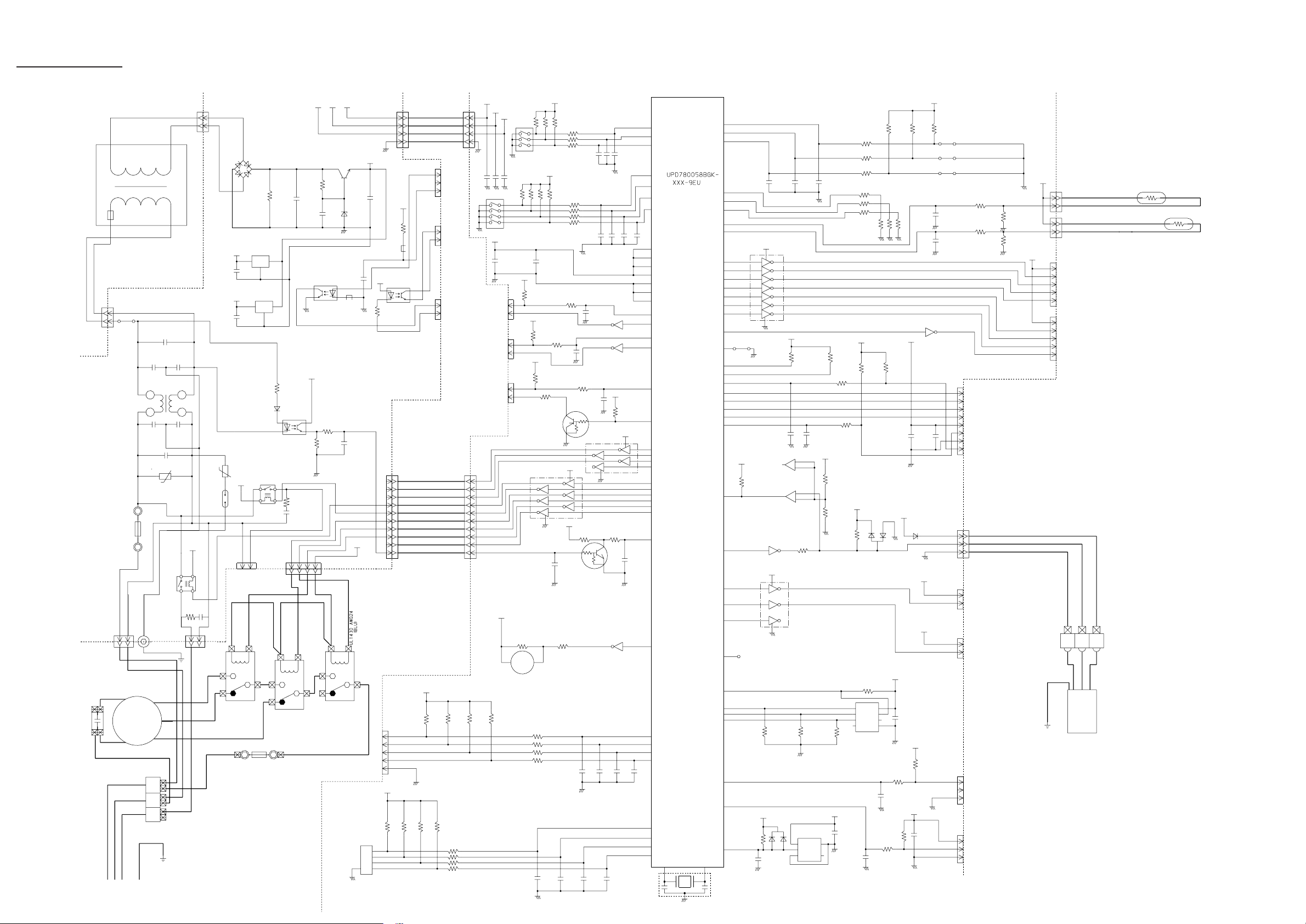
O U T D O O R P R I N T E D C I R C U I T B O A R D
C I R C U I T D I A G R A M
Model : AOG60RPAGT
CONTROLLER PCB ASSEMBLY ( MAIN PCB )
INDOOR UNIT
R46 3.3 <RC-5W>
CN7
B3P5-VH-B-C
BLACK
CN7-1
CN7-2
CN7-3
UL1015 AWG16
D14
D3SB60
C28
VA2 470V
<TNR>
4700P
<ECQM>
D19 1SR139-600
D23 1SR139-600
D18
MTZJ5.1B
R70 330
<1/4W>
C3
0.022
<YE>
C4
0.022
<YE>
VA3 470V
<TNR>
R68 330K
<2W>
Q9
2SC4236
C27
+
100/
450V
R69 100
<1/10W>
Q10
2SC1815
R67 1.5
<RS-2W>
F1
6.3A
<BET>
FH1
FH2
VA1 470V
<TNR>
SA1
E
GREEN
RA-362M
D21
D1FL20U
C35
0.047
<ECQB>
R81 62K
<RS-2W>
R71 100
<1/2W>
D20
D1FL20U
+
C1
0.22
<YE>
C37
100/
6.3V
005A
<ELF15N>
TR-175D
3
5
4
1
2
SWITCHING
TRANSFORMER
LF1
C2 0.22
<RE>
T1
C49
0.01
<F>
D2
D2FL20U
9
10
R2 10K
<1/4W>
11
8
7
D3
D2FL20U
+
14
10
18
C5
1000
/25V
C6
+
1000
/50V
14V
R45 10K
<1/10W>
I C7 HU2001
I C9
7824
I
G
24V
O
7805
C10
+
100/
35V
I C2
I
5V
O
G
5V
R5 4.7K
<1/10W>
2
3
1
5V
5
4
W1
14V
5V
R82 56K
<RS-1W>
D1
D1F60
K 2
K 1
K 4
K 3
K 7
K 5
R23 10K <1/10W>
R24 10K <1/10W>
R25 10K <1/10W>
R34 10K <1/10W>
R35 10K <1/10W>
R36 10K <1/10W>
PC1
TLP621
<GB>
14V
5V
R1 4.7K
<1/10W>
C7
0.01
<F>
I C3-1 uPA2003
I C3-2 uPA2003
I C3-3 uPA2003
I C3-4 uPA2003
I C3-5 uPA2003
I C3-6 uPA2003
I C3-7 uPA2003
LED1 SLR-325 <RED>
LED4 SLR-325 <RED>
LED2 SLR-325 <RED>
LED5 SLR-325 <RED>
LED3 SLR-325 <RED>
LED6 SLR-325 <RED>
POWER SOURCE
415 / 380V
50Hz
E
TERMINAL
1
2(N)
3
N
T
S
R
E
UL1015 AWG14
MAGNETIC
RELAY. A
FC-1SZ374
COMPRESSOR A
GREEN / YELLOW
UL1015 AWG20 RED
WHITE
BLACK
UL1015 AWG14
UL1015 AWG14
R S T
COMP.
A
CN2
BLACK
WHITE
RED
BLUE
BLACK
WHITE
RED
BLUE
CN4-2
CN4-1
B2P3-VH-B-Y
YELLOW
CN2-1
CN2-2
CN3
B4P7-VH-B
C55
WHITE
0.22 <RE>
CN3-1
CN3-2
CN3-3
CN3-4
CN15
B2P3-VH-B-Y
YELLOW
CN15-1
CN15-2
CN16
B4P7-VH-B-R
RED
CN16-1
CN16-2
C56
0.22 <RE>
CN16-3
CN16-4
CN4
179844-1
WHITE
CN6-2
CN6-1
CN6
179844-4
YELLOW
CN22-1
CN22-2
CN22
B2P3-VH-B-R
RED
R83 120
<1/2W>
K2
G5S-1
C59 0.22 <RE>
R87 120
<1/2W>
K1
FTR-F3A
R84 120
<1/2W>
K4
G5S-1
C57 0.22 <RE>
R85 120
<1/2W>
K3
FTR-F3A
K5
FTR-F3A
K7
FTR-F3A
K10
FTR-F3A
FAN CAPACITOR-1
4uF
450V
UL1015 AWG20 YELLOW
UL1015 AWG20 BLACK
UL1015 AWG20 WHITE
UL1015 AWG20 PINK
BLACK
WHITE
UL1015 AWG20
YELLOW
UL1015 AWG20
UL1015 AWG20
FAN
MOTOR
WHITE
UL1015 AWG18
BLUE
UL1015 AWG14
RED
GRAY
1
FAN CAPACITOR-2
4uF
450V
UL1015 AWG20 YELLOW
RED
BLUE
BLACK
WHITE
UL1015 AWG20
UL1015 AWG20
UL1015 AWG20
YELLOW
UL1015 AWG20
UL1015 AWG20
FAN
MOTOR
2
UL1015 AWG14
UL1015 AWG14
CR
0.1/120
RED
BLUE
UL1015 AWG20
UL1015 AWG20
BLACK
4WV.
A
N
4-WAY VALVE-A
BELT HEATER
BLACK
UL1015 AWG20
BLACK
UL1015 AWG20
BLACK
UL1015 AWG20 WHITE
UL1015 AWG20 BLACK
C8
0.22
<RE>
2004.06.30 9
C47
100/
6.3V
R10 10K
<1/10W>
C12
0.1
<F>
Q3
DTC124EKA
C13
0.1
<F>
Q14
DTC124EKA
Q8
DTC124EKA
5V
C46
+
0.1
<F>
R9
10K
<1/10W>
5V
5V
R3 4.7K
<1/10W>
EZ-002HHUE-C
C45
0.1
<F>
R8 1.0K
<1/10W>
5V
R4 4.7K
<1/10W>
C14
0.01
5V
<F>
R7 1.0K
<1/10W>
C15
1000P
<R>
C48
0.01
<F>
CR63
NC
NC
NC
NC
NC
24
VDD1
10
VDD0
34
AVREF
35
AVDD
XT1
38
GND1
42
25
AGND
9
GND0
27
P16
I C 1
uPD780024AGK
-C15-9ET
43
P00
23
P25
P20
18
19
P21
33
P10
45
P02
37
XT2
20
P22
7
P56
8
P57
63
P46
62
P45
61
P44
60
P43
59
P42
58
P41
57
P40
P50
1
2
P51
3
P52
4
P53
5
P54
6
P55
X1
41 40
1
RESET
2
56
P67
55
P66
54
P65
53
P64
52
P75
51
P74
50
P73
49
P72
46
P03
48
P71
47
P70
44
P01
26
P17
64
P47
36
39
I C
22
P24
21
P23
15
P34
16
P35
17
P36
11
P30
12
P31
13
P32
14
P33
C41
32
P11
31
P12
30
P13
29
P14
28
P15
X2
3
X1
8.38MHz
EF0EC8384T4
I C4-7 uPA2003
I C4-6 uPA2003
I C4-5 uPA2003
I C4-4 uPA2003
I C4-3 uPA2003
I C4-2 uPA2003
I C4-1 uPA2003
NC
R54 1.0K
<1/10W>
CR62
0.01
<F>
C54
5V
R40 10K
<1/10W>
C44
0.1
<F>
JM4
R57 R58R56
10K <1/10w> x 3
C40 C39 C38
C23
C22
C24
R49 10K
<1/10W>
R26 1.0K
<1/10W>
C51 C52 C53
1
3
2
I C6
PST600C
0.01 <F> x 4
1000P <R> x 3
24V
10K <1/10W> x 4
5V
1
CS
VCC
2
SK
3
D1
NC
GND
6
I C10
NM93C46
R59 10 <1/10W>
R60 10 <1/10W>
R61 10 <1/10W>
R62 10 <1/10W>
14V
Q5
2SC2712
5V
R27 10K
<1/10W>
R80
R77
R78
R79
0.01 <F> x 4
C43
0.1
<F>
R44 10K
<1/10W>
8
D0
4
NC
7
5
R30
R31
R32
R33
1.0K <1/10W> x 4
R11 1.0K <1/10W>
R12 1.0K <1/10W>
R13 1.0K <1/10W>
R14 1.0K <1/10W>
R15 1.0K <1/10W>
24V
K 10
D6
DA226U
CN13
B2P-VH-B
WHITE
C42
0.1
<F>
5V
R47 R51 R52
1.0K <1/10W> x 4
R92 10K
<1/10W>
5V
C36
0.1
<F>
RJ21
CN11
B6B-XASK-1-A
WHITE
14V
MAGNETIC
COMP. A
CN13-1 UL1015 AWG20 BLUE
CN13-2 UL1015 AWG20 BLUE
R76
5V
5V
10K <1/10W> x 4
R38
R37
R18 14K (1%) <1/10W>
R19 6.65K (1%) <1/10W>
RJ20
CN11-1
CN11-2
CN11-3
CN11-4
CN11-5
CN11-6
8
7
6
5 4
SW1
DSS804
R39
R43
R17 38.3K (1%) <1/10W>
UL1430 AWG24 RED
UL1430 AWG24 BROWN
UL1430 AWG24 BLUE
UL1430 AWG24 ORANGE
UL1430 AWG24 YELLOW
UL1430 AWG24 WHITE
PRESSURE
SWITCH A
PRES.
SW
A
1
DEFROST
DEFROST TEMP.
2
3
PUMP DOWN
FAN LOW NOISE
CN14
B5P-SHF-1AA
WHITE
CN14-1
CN14-2
CN14-3
CN14-4
CN14-5
C19
C17
C18
TEST
0.1 <F> x 3
5V
EEV-A
CN9
B6B-XAKK-1-A
BLACK
ELECTRIC
EXPANSION VALVE-A
CN9-1
CN9-2
CN9-3
CN9-4
CN9-5
CN9-6
BLACK
BROWN
GREEN
THERMISTOR
TUBE
PIPE TEMP. TH.
R0=16.05K
B0 / 25=3873K
DISCHARGE TEMP. TH. A
R100=3.43K
OUTDOOR TEMP. TH.
R25=10.00K
B25 / 50=3950K
B50 / 100=4012K
Page 11

D I P - S W I T C H S E T T I N G
�œIndoor Unit
SW1
DIP-Switch
SW2
DIP-Switch
Jumper wire
NO.
1
2
3
4
NO.
1
Ceiling setting(+4�Ž) Room setting(0�Ž)
2
3
NO.
JM1
JM2
JM3
OFF
OFF
SW state
*
*
*
*
SW state
*
PulseEdge
*
InvalidityValidity
*
SW state
*
CommercialResidencial
*
Heater settingNomal
*
ON
Out of Use
ON
Remote sensor setting
Control input setting
Auto restart
DisconnectConnect
Out Of Use
Commercial mode setting
Heater setting
Detail
Detail
setting
Detail
�œRemote Controller
NO.
1
2
3
DIP-Switch
Jumper wire
One Unit Multiple Unit
4
5
Invalidity Validity
6
Invalidity Validity
NO.
J5
OFF
Connect
3 speed
(HI,MED,LO)
SW state
*
*
Cooling Only modelHeat & Cool model
*
SW state
*
ON
Disconnect
1 speed
(HI)
Detail
*
Dual remote controller setting
Group control
Model s
Auto changeover
*
Memory buckup setting
Fan speed setting(for AR90)
setting
etting
setting
Detail
�FFactory setting
*
2004.06.23 10
Page 12

ERROR DISPLAY
CAUTION
Supply power to the crankcase heater for at least
12 hours before the start of operation in winter.
(1) Stop the air conditioner operation.
(2) Press the master control button and the fan control button
simultaneously for 2 seconds or more to start the test run.
Test run display
(3) Press the start/stop button to stop the test run.
[SELF-DIAGNOSIS]
When the error indication E:EE is displayed, follow the following items to perform the self-diagnosis. E:EE indicates an error
has occurred.
1. REMOTE CONTROLLER DISPLAY
1) Stop the air conditioner operation.
2) Press the set temperature buttons simultaneously for
5 seconds or more to start the self-diagnosis.
Refer to the following tables for the description of each error
code.
Unit number
(usually 0)
Error code
SUMOTUWETH FR
SA
Error code Error contents
09
0A
0b
0c
0d
0E
0F
11
12
13
14
Float switch operated
Outdoor temperature sensor open
Outdoor temperature sensor short-circuited
Discharge pipe temperature sensor open
Discharge pipe temperature sensor shortcircuited
Outdoor high pressure abnormal
Discharge pipe temperature abnormal
Model abnormal
Indoor fan abnormal
Outdoor signal abnormal
Outdoor EEPROM abnormal
2. OUTDOOR UNIT LEDS
Heat & Cool model (reverse cycle) only
When a malfunction occurs in the
outdoor unit, the LEDs on the circuit board light to indicate the error.
Refer to the following table for the
description of each error according
to the LEDs.
LED layout
LE D3
LE D2
LE D1
LE D6
LE D5
LE D4
Ex. Self-diagnosis
(3) Press the set temperature buttons simultaneously for
5 seconds or more to stop the self-diagnosis.
Error code Error contents
00
01
02
03
04
05
06
07
08
Communication error
(indoor unit
Communication error
(indoor unit outdoor unit)
Room temperature sensor open
Room temperature sensor short-circuited
Indoor heat exchanger temperature sensor
open
Indoor heat exchanger temperature sensor
short-circuited
Outdoor heat exchanger temperature
sensor open
Outdoor heat exchanger temperature
sensor short-circuited
Power source connection error
remote controller)
E rror co ntents LE D1 LE D2 LE D3 L ED 4 L ED 5 LE D6
S ignal abno rma l
Ind oor uni t abno rma l
Dischar ge pip e
tem peratu re abno rmal
Ou tdoor heat e xch ange r
tem peratu re abno rmal
Ou tdoor temp eratur e
ab norm al
Po wer sor ce c onnection
er ror
E EPR OM ab norm al
Ou tdoor high pre ss ure
ab norm al
Dischar ge pip e
tem peratu re abno rmal
: 0.5s O N/0.5 s O FF ( flas h) : OFF
: 0.1s O N/0.1 s O FF ( flas h) : Inde finite
When the fault is cleared, the LED lamp goes off.
However, for discharge pipe temperature abnormal and high pressure abnormal, the LED lamp lights continuously for 24 hours, as
long as the power is not turned off.
2004.06.23 11
Page 13

DISASSEMBLY ILLUSTRATION
(Indoor Unit)
Models : ARG60AUAK
ARG60RUAK
64
74
70
61
59
73
60
62
19
68
69
329
72
146
71
2004.06.30 12
66
Page 14

Models : ARG60AUAK
ARG60RUAK
553
823
824-3
815-2
455
815-1
37
237
38
846
824-5
236
2004.06.30 13
Page 15

Models : AOG60APAGT
AOG60RPAGT
527
373
9
168
46-3
803
734
169
5
6
30
4
813
805
822
2
2004.06.30
14
Page 16

Model : AOG60APAGT
807
470
2004.06.30 15
Page 17

Model : AOG60RPAGT
2004.06.30 16
Page 18

Model : AOG60APAGT
2004.06.30
17
Page 19

Model : AOG60RPAGT
2004.06.30 18
Page 20

PARTS LIST (Indoor unit)
Ref.
No.
19 DRAIN PAN ASSY PRINTED
37 CAPACITOR,PLASTIC 9704436146
38 CAPACITOR CLAMP
59 SIROCCO FAN
60 CASING B
61 CASING A
62 MOTOR, INDUCT 9601688013
64 KIT (PANEL FRONT SUB ASSY)
66 DRAIN PAN SUB ASSY
68 KIT (PANEL RIGHT SUB ASSY) 9372916018
69 PLATE TOP SUB ASSY 9372576014
71 KIT (PANEL REAR SUB ASSY)
70 BRACKET MOTOR ASSY
72 KIT (PANEL LEFT SUB ASSY)
73 COVER BOX 9372061008
74 PANEL FAN ASSY
146 EVAPORATOR ASSY 9372585016
236
237 CONTROLLER PCB ASSY 9705246027
329 DISTRIBUTOR ASSY
POWER PCB ASSY
Description
ARG60AUAK ARG60RUAK
9372047026
9308114006
9372059012
9372058015
9372057018
9372637012
9372053003
9372636015
9372037003
9372581018
9372035009
9705271029
(EZ-00304WSE-C) (EZ-003SHSE-C)
9372587010
Parts No.
Ord.
Q'ty
9372047026
9704436146
9308114006
9372059012
9372058015
9372057018
9601688013
9372637012
9372053003
9372916018
9372576014
9372636015
9372037003
9372581018
9372061008
9372035009
9372585016
9705271012
9705246010
9372587010
455 CONTROL BOX ASSY
553 TRANSFORMER (POWER)
815-1
823
824-3
824-5 FUSE
846 RELAY
TERMINAL 3P
TERMINAL 3P815-2
FUSE HOLDER
FUSE
---
THERMO. SPRING-A
--- PIPE THERMISTOR
--- ROOM THERMISTOR
--- REMOCON ASSY
9372536001
9704129017
9306489045
9703345012
0501454012
0600222512
0600315023
9702100018
313728262708
9703297113
9703299216
9372266021
When you order parts, please make a photocopy of this page
and fill the number of the parts in the “Order” column.
9372536001
9704129017
9306489045
9703345012
0501454012
0600222512
0600315023
9702100018
313728262708
9703297113
9703299216
9372266014
2004.06.30 19
Page 21

OUTDOOR UNIT
Ref.
No.
Description
2 Fan Cover
4 Emblem-Rear
5 Cabinet-A, Painted
6 Cabinet-C, Painted
9 Cabinet-B, Painted
12 Base Assy, Painted
15 Dryer
16-1 Condenser-A Assy
16-2 Condenser-B Assy
Part No.
AOG60APAGT
9352159015
313791088308
9352146015
9352149016
9352147012
9352136016
9368111014
9369546006
9369547003
18-1 Suction Pipe-A 9364513003
18-4 Suction Pipe
26 Compressor Cover-A
29 Separate Wall Assy
30 Blower Cover, Painted
32 Control Box Metal
Capacitor (Fan Motor)34
36
Cord Holder Metal
39 Propeller Fan Assy
41 Fan Motor Assy
Bracket (Motor) Assy
45
46-3
Compressor Assy
48
Bracket (Coupler) Assy
55 Special Nut M8
107 Rubber Seat-A (For Comp.)
108 Sleeve-A (For Comp.)
109 Terminal Cover (For Comp.)
111 Terminal Packing (For Comp.)
168 Cabinet-E, Painted
9364054001
9370774030
9355277013
9352151019
9352134012
9704305015
9356934007
9366378013
9600832028
9371639017
9370067002
9355281010
9355091008
9364084008
9364085005
9364087009
9364086002
9361312029
169 Cabinet-F, Painted 9361311022
182 Clamp No.249 313361271505
Ord.
Q’ty
Ref.
No.
Description
184-1 Thermo. Spring -A
185 Rubber Bushing
Part No.
AOG60APAGT
313728262708
313005066051
259 Muffler 9368082000
333-2 Accumulator(B)
334 Suction Pipe-B
9371615011
9352287008
373 Grip 9352157004
401 Terminal-2P 9701971015
405 Clamp No. 1763 313816345304
407 Clamp (Cable) No. 1259 313739340109
470 Separate Wall-B Assy 9361310001
Protection Net
527
Thermister Outdoor
549
620 Inlet Pipe (Condenser) Assy
646 Compressor Cover-B
734 Cabinet Top Plate
735
Distributor Assy
788
Thermister - Over heat
790-1 Belt Heater-A
9361730007
9352426001
9361558007
9370774047
9352161018
9361561007
9354061002
9361140042
791 Magnetic Relay 9900227012
803 Cabinet-D, Painted
9352150012
805 Blower Cover Corner 9352160011
807 Inlet Pipe (Accumulator) 9352285004
809 Ball Valve-A
810 Ball Valve-B
813 Cabinet Hook
815-2 Terminal 8P
9371799049
9371799056
9352148002
9363276022
816 Wire Clamp Metal 313584219902
817 Thermostat Fixture 9352164019
821 Joint Pipe B 9352284007
822 Fan Cover Fixture-A
9352158018
Ord.
Q’ty
823 Fuse Holder 0501454012
824-5 Fuse 0600315023
826 Condensing Pipe-B
880-1 Network
9361557000
9700987017
863 Joint Pipe (Capilally)-B 9353206008
When you order parts, please make a photocopy of this page
and fill the number of the parts in the “Order” column.
2004.06.30 20
Page 22

OUTDOOR UNIT
When you order parts, please make a photocopy of this page
and fill the number of the parts in the “Order” column.
Ref.
No.
2 Fan Cover
4 Emblem-Rear
5 Cabinet-A, Painted
6 Cabinet-C, Painted
9 Cabinet-B, Painted
12 Base Assy, Painted
15 Dryer
16-1 Condenser-A Assy
16-2 Condenser-B Assy
18-1 Suction Pipe-A 9364513003
18-4 Suction Pipe
21 Discharge Pipe-B Assy
26 Compressor Cover-A
29 Separate Wall Assy
30 Blower Cover, Painted
32 Control Box Metal
34 Capacitor (Fan Motor)
36 Cord Holder Metal
39 Propeller Fan Assy
41 Fan Motor Assy
45 Bracket (Motor) Assy
46-3 Compressor Assy
48 Bracket (Coupler) Assy
55 Special Nut M8
107 Rubber Seat-A (For Comp.)
108 Sleeve-A (For Comp.)
109 Terminal Cover (For Comp.)
111 Terminal Packing (For Comp.)
168 Cabinet-E, Painted
169 Cabinet-F, Painted
Description
Part No.
AOG60RPAGT
9352159015
313791088308
9352146015
9352149016
9352147012
9352136016
9368111014
9371389103
9371389097
9364054001
9368331009
9370774030
9355277013
9352151019
9352134012
9704305015
9356934007
9366378013
9600832028
9371639017
9370067002
9355281010
9355091008
9364084008
9364085005
9364087009
9364086002
9361312029
9361311022
Ord.
Q’ty
Ref.
No.
344-2 4-Way Valve
354 Pressure Switch
373 Grip
381 Locking Spacer
405 Clamp No. 1763
407 Clamp (Cable) No. 1259
450 Discharge Pipe A
470 Separate Wall-B Assy
527 Protection Net 9361730007
575 Condensing Pipe C
620 Inlet Pipe (Condenser) Assy
628 Locking Spacer-B
646 Compressor Cover-B
678 Bracket (Thermistor)
734 Cabinet Top Plate
735 Distributor Assy
790-1 Belt Heater-A
791 Magnetic Relay
803 Cabinet-D, Painted 9352150012
805 Blower Cover Corner 9352160011
807 Inlet Pipe (Accumulator) A 9363458008
809 Ball Valve-A
810 Ball Valve-B
813 Cabinet Hook
815-2 Terminal 8P
816 Wire Clamp Metal 313584219902
821 Joint Pipe (Valve-B)
822 Fan Cover Fixture-A
825-1 Expansion Valve
826 Condensing Pipe-B
Description
Part No.
AOG60RPAGT
9353532008
9704045003
9352157004
313209391506
313816345304
313739340109
9368338008
9361310001
9363460001
9361558007
313005446558
9370774047
313557406106
9352161018
9361561007
9361140042
9900227012
9371799049
9371799056
9352148002
9363276022
9353307002
9352158018
9900170028
9361557000
Ord.
Q’ty
182 Clamp No.249
184-1 Thermo. Spring -A
185 Rubber Bushing
236 Controller PCB Assy
272 Strainer Assy
330 Inlet Pipe (Cond. )-A
333 Accumulator
333-2 Accumulator(B)
334 Suction Pipe-B
343 Solenoid Coil
313361271505
313728262708
313005066051
9704764096
9354139008
9361573000
9350363018
9371615011
9352287008
9359616108
857 Inlet Pipe (Accumulator) B
862 Valve-B Coupl. Pipe 9353309006
880-1 Network
918 Thermistor Assembly
919 Expansion Valve Coil
9363459005
9700987017
9900129019
9900172015
2004.06.30 21
Page 23

STANDARD ACCESSORIES
INDOOR UNIT ACCESSORIES OUTDOOR UNIT ACCESSORIES
Name and Shape
Special nut A
(large flange)
Special nut B
(small flange)
Coupler heat
insulation (large)
Coupler heat
insulation
(small)
Binder (small)
Remote
controller
Tapping screw
(flush heads)
Remote controller cord
Q’ty Q’ty
4
4
1
1
1
1
2
1
Application
For suspending the
indoor unit from ceiling
For indoor side pipe
joint (large pipe)
For indoor side pipe
joint (small pipe)
For fixing the remote
controller cord
For installing the
remote controller
For connecting the
remote controller
Name and Shape
Power cap
1
Auxiliary pipe assembly
1
Edge cover
1
Tapping screw
2
Binder
1
Putty
1
Coupler heat insulation
1
Pipe (drain)
2
Flexible tube
2
Cap (drain)
2
Application
For power supply cord
installation
For wiring conduit
(gas side) connection
(May not be supplied,
depending on the model)
For wiring conduit
installation hole edge
protection
For cabinet A and
cabinet D mounting (1)
Spare (1)
For power supply cord
binding
For sealing
For outdoor side pipe
joint
For outdoor unit drain
piping work (May not be
supplied, depending on
the model.)
2004.06.30 22
Page 24

0404G2585
 Loading...