

Page 1

SPLIT TYPE AIR
CONDITIONER
DUCT
type
(50Hz)
Models
Indoor unit Outdoor unit
ARG60ALA3 AOG60ABA3L
ARG60RLA3 AOG60RBA3L
CONTENTS
SPECIFICATIONS
OUTLINE AND DIMENSIONS
REFRIGERANT SYSTEM DIAGRAM
CIRCUIT DIAGRAM
INDOOR PCB CIRCUIT DIAGRAM
. . . . . . . . . . . . . . . . . . . . . . . . . . .
. . . . . . . . . . . . . . . .
. . . . . . . . . . . . . . . . . . . . . . . . .
. . . . . . . . . . . . .
. . . . . . . . . . . . . . . . . . . . . . . . . . . . . . .
. . . . . . . . . . . . . . . .
. . . . . . . . .
. . . . . . . . . . .
1
3
4
5
7
10DISASSEMBLY ILLUSTRATION
19PARTS LIST
21STANDARD ACCESSORIES
Page 2

SPECIFICATIONS
INDOOR UNIT
OUTDOOR UNIT
COOLING CAPACITY
HEATING CAPACITY
16.4 kW - 17.0 kW
ELECTRICAL SPECIFICATIONS
POWER SUPPLY
FREQUENCY
RUNNING CURRENT
INPUT
EER
MOISTURE REMOVAL
AIR CIRCULATION - Hi
COOLIING
HEATING
COOLIING
HEATING
COOLIING
HEATING
5.80 kW - 5.90 kW
2.83 - 2.88 kW/kW
COMPRESSOR
TYPE
ARG60ALA3
AOG60ABA3L
16.4 kW - 17.0 kW
-----
17.0 kW - 17.6 kW
380V - 415V
50 Hz
9.8 A - 9.8 A
-----
5.80 kW - 5.90 kW
-----
4.90 kW - 5.05 kW
2.83 - 2.88 kW/kW
-----
3.47 - 3.49 kW/kW
6.5 L/hr
3,000 m3/hr
Hermetic type, 2 pole,
3 - phase, Induction motor
ARG60RLA3
AOG60RBA3L
9.8 A - 9.8 A
8.7 A - 8.7 A
DISCRIMINATION
FAN MOTOR
POWER SUPPLY
INDOOR UNIT
OUTDOOR UNIT
DIMENSIONS
INDOOR UNIT
OUTDOOR UNIT
WEIGHTS
INDOOR UNIT
OUTDOOR UNIT
DISCRIMINATION
HI-SPEED
MED-SPEED
LO-SPEED
DISCRIMINATION
HI-SPEED
H x W x D
H x W x D
Net / Gross
Net / Gross
H26A72QDBEA
380V - 415V
MFA-60ETM
1,150 r.p.m.
1,075 r.p.m.
1,000 r.p.m.
MFB-362F
820 r.p.m.
400 x 1,250 x 800 mm
1,355 x 940 x 370 mm
75 kg / 90 kg
121 kg / 136 kg 129 kg / 144 kg
2006.04.19
ADDITIONAL REFRIGERANT CHARGE (R-22)
PIPE LENGTH
FULL CHARGE
AMOUNT
ADDITIONAL CHARGE
20 m (66 ft)
30 m (99 ft)
40 m (132 ft)
50 m (164 ft)
4,800 g (169.6 oz)
5,400 g (190.8 oz)
6,000 g (212.0 oz)
6,600 g (233.2 oz)
60 g/m (0.64 oz / ft)
1
Page 3
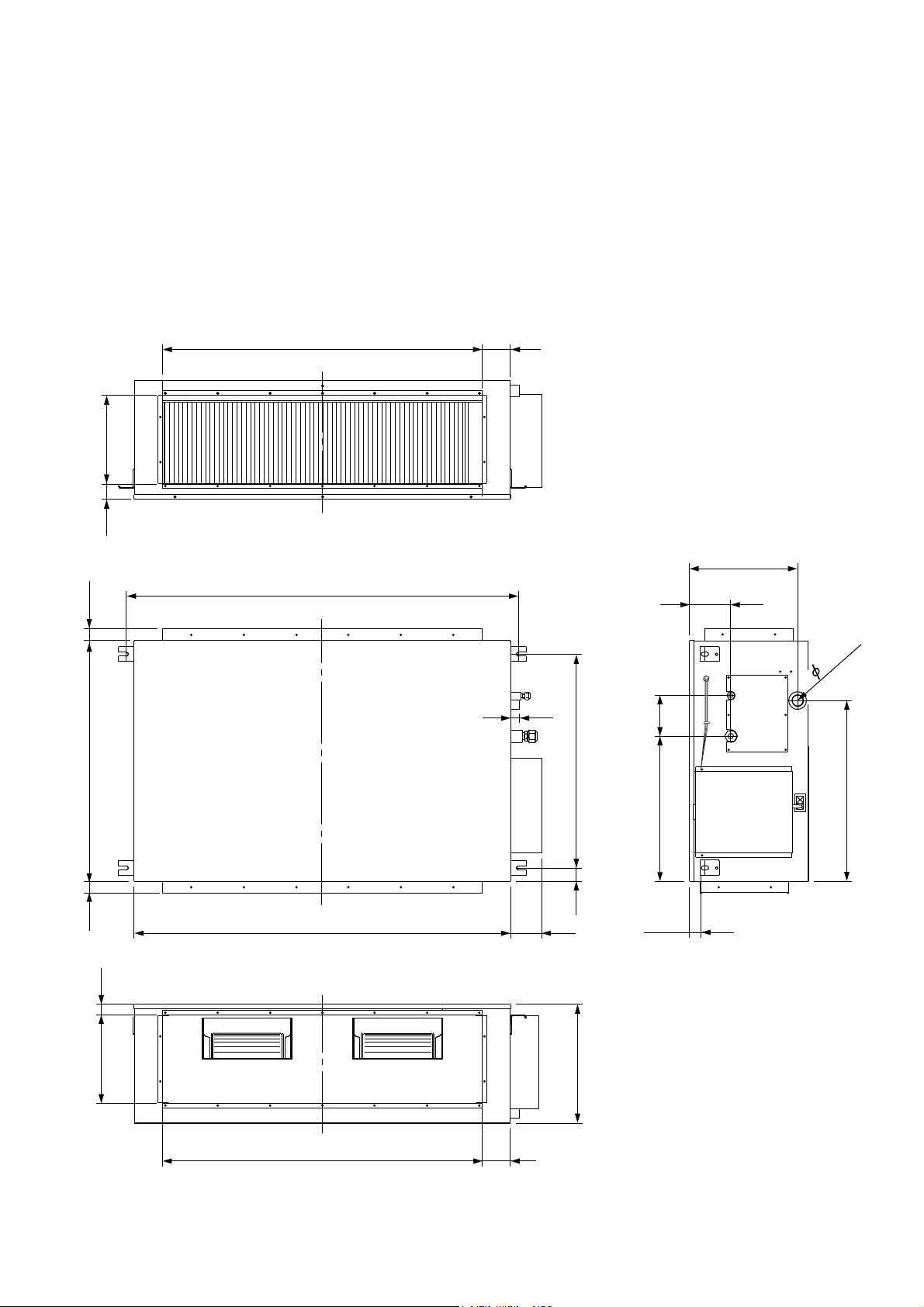
OUTLINE AND DIMENSIONS
INDOOR UNIT
Models :
ARG60ALA3
ARG60RLA3
( unit : mm )
1,063 93
29550
359
1,300
(HOOK)
30
800
39 39
1,250
103
71045395
(HOOK)
(HOOK)
134483
38
137.5
38.1
(D
600
RAIN)
295 34
1,063 93
2006.04.19 2
Page 4

OUTDOOR UNIT
Models :
AOG60ABA3L
AOG60RBA3L
( unit : mm )
370
1,355
23
425
400
650
940
2006.04.19 3
Page 5
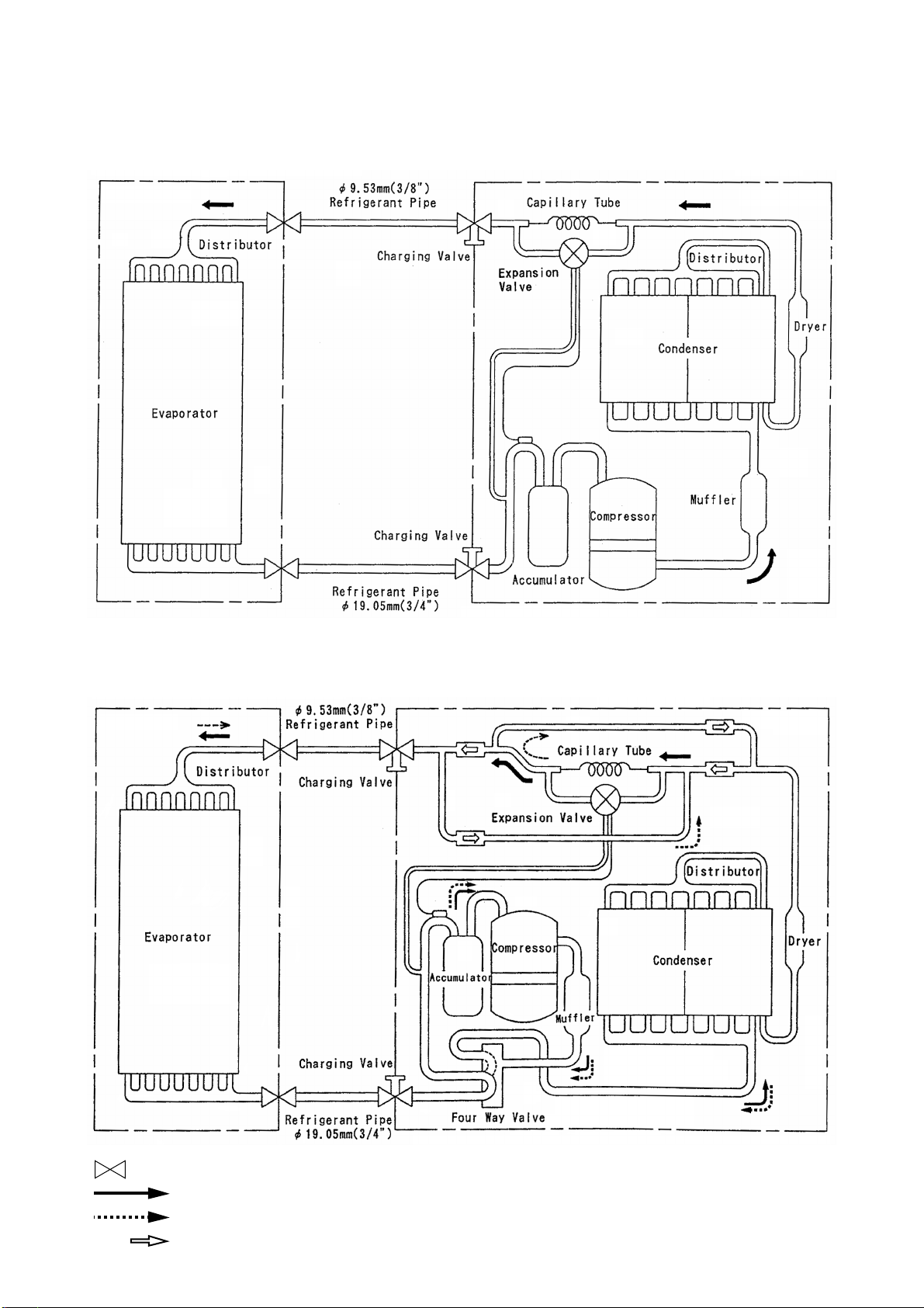
REFRIGERANT SYSTEM DIAGRAM
Models : ARG60ALA3 / AOG60ABA3L
Outdoor unitIndoor unit
Models : ARG60RLA3 / AOG60RBA3L
Outdoor unitIndoor unit
: Flare coupling
Cooling
Heating
Check valve
2006.04.20 4
Page 6
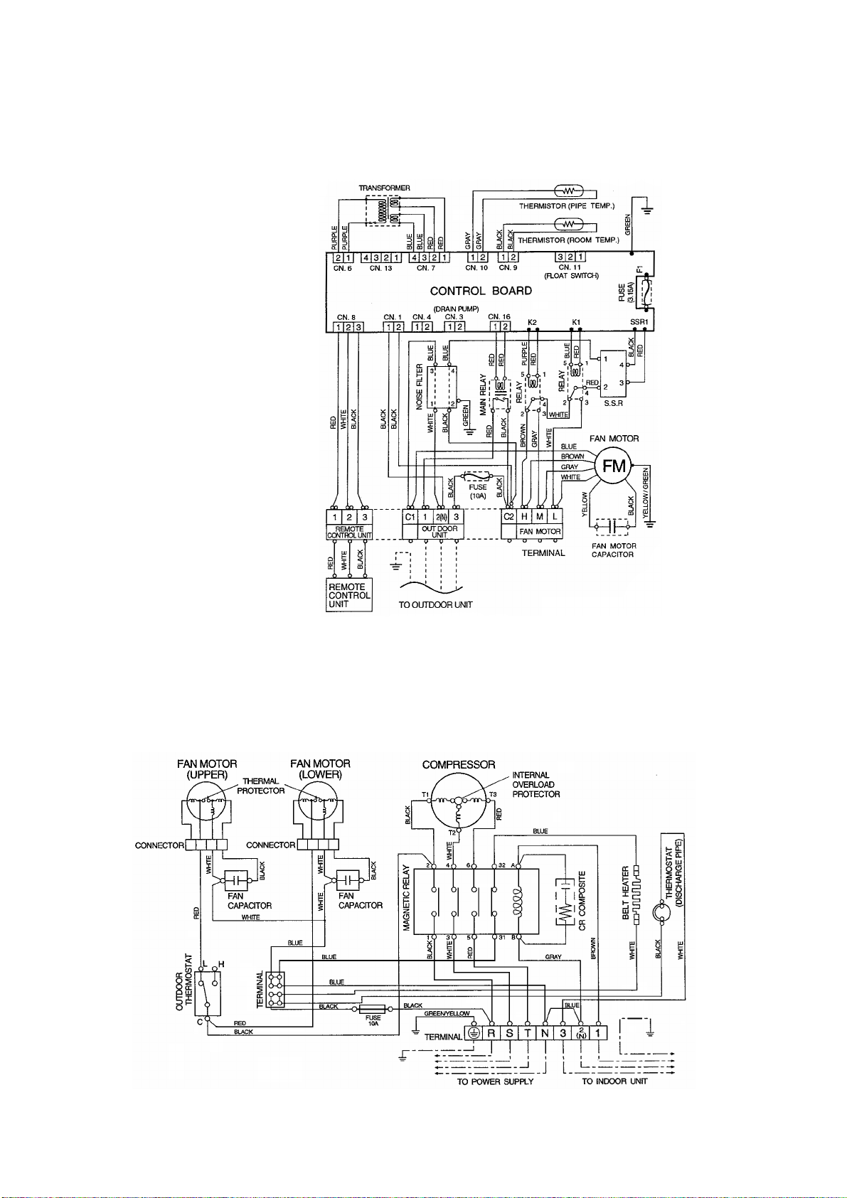
CIRCUIT DIAGRAM
Models : ARG60ALA3 / AOG60ABA3L
INDOOR UNIT
OUTDOOR UNIT
FAN MOTOR CAPACITOR 15uF
FAN MOTOR CAPACITOR 4uF
2006.04.20 5
Page 7

Models : ARG60RLA3 / AOG60RBA3L
INDOOR UNIT
OUTDOOR UNIT
FAN MOTOR CAPACITOR 15uF
FAN MOTOR CAPACITOR 4uF
2006.04.20 6
Page 8

INDOOR PCB CIRCUIT DIAGRAM
Model : ARG60ALA3
2006.04.20 7
Page 9

Model : ARG60RLA3
2006.04.20 8
Page 10

OUTDOOR PCB CIRCUIT DIAGRAM
Model : AOG60RBA3L
2006.04.20 9
Page 11

DISASSEMBLY ILLUSTRATION
Models :
ARG60ALA3
ARG60RLA3
275
108
173
468
64
160
253
924
255
146
254
255
235
184-1
195
625
652-1
234
238
329
238
273
2006.04.20 10
735
173
324
287
495
69
185-1
514
277
Page 12

Models :
ARG60ALA3
ARG60RLA3
10
477
422
75
126
117-3
109
422
45
164
338-1
477
338-2
477
56-2
109
56-1
477
2006.04.20 11
Page 13

Model : ARG60ALA3
2006.04.20 12
Page 14

Model : ARG60RLA3
2006.04.20 13
Page 15

Models :
AOG60ABA3L
AOG60RBA3L
2006.04.20 14
Page 16

Model : AOG60ABA3L
2006.04.20 15
Page 17

Model : AOG60RBA3L
2006.04.20 16
Page 18

Model : AOG60ABA3L
Model : AOG60RBA3L
2006.04.20 17
Page 19

Model : AOG60RBA3L
Model : AOG60ABA3L
2006.04.20 18
Page 20

PARTS LIST
INDOOR UNIT
Ref.
Description
No.
10 Reinforcement (Front Panel)
34 Capacitor (Fan Motor)
45 Motor Mount Assy
56-1 Sirocco Fan-R
56-2 Sirocco Fan-L
64 Left Panel Assy
69 Right Panel Assy
75 Front Panel
77 EMI Filter
108 Base
9361424005
9700468042
9361369009
9361635005
9361636002
9361358003
9361356009
9361353008
9702126018
9361340008
Part No.
ARG60RLC3ARG60ALC3
9361424005
9700468042
9361369009
9361635005
9361636002
9361358003
9361356009
9361353008
9702126018
9361340008
Ord.
Q’ty
109 Casing Assy
117-3 Hex. Nut w/Spring Washer
126 Motor Base Assy
146 Evaporator Assy
160 Drain Pan Assy
164 Fan Motor Assy
173 Hook Metal
184-1 Thermostat Spring-A
185-1 Rubber Bushing
195 Clamp SKB-100
210 Main Relay
223
233
234 Thermistor (Room)
235 Thermistor (Pipe)
236 Controller PCB Assy
238 Rectangular Flange
240 Remote Control Unit
253 HE Support-Right
254 HE Support-Left
255
270
273
275
277
287
224
329
338-1
338-2
Control Box Metal
Power Transformer
HE Support-Sub
Relay, Solid
Rear Panel Assy
Under Panel
Maintenance Panel
Cap (Power)
Top Plate
Coupling Pipe Assy
Motor Fixture
Motor Fixture-B
9361373006
301721180114
9361354005
9361436008
9361341029
9361439009
9361367005
313728262708
9357376004
313361275805
9356781007
9361365001
9701678013
9701390021
9701329069
9702091026
9361351004
9701673032
9361344006
9361345003
9361346000
9702099015
9361350007
9361362000
9361364004
9352173011
9361349001
9361445000
9359702009
9359703006
9361373006
301721180114
9361354005
9361436008
9361341029
9361439009
9361367005
313728262708
9357376004
313361275805
-------9361365001
9701678013
9701390021
9701329069
9702406028
9361351004
9701673025
9361344006
9361345003
9361346000
9702099015
9361350007
9361362000
9361364004
9352173011
9361349001
9361445000
9359702009
9359703006
380
381-4
422
430
466
468
477
495
514
625
652-1
735
815
823
824-3
824-5
846
924
982-1
982-2
Locking Spacer KGLS-6S
Locking Spacer KGPS-6S
Clamp NK-9N
Clamp NK-7N
Clamp NK-4N
Nut-A M8
Bell-Mouth
Clamp No. 2U46
Control Box Cover
Cord Bushing
Therm. Holder Pipe
Distributor Assy
Terminal 11P
Fuse Holder
Fuse
Fuse
Relay
Seal Plate
Cord Clamp-A
Cord Clamp-B
313209391403
0600118075
313209399700
313095365602
313714328805
9356998009
9361378001
9352715006
9361366008
9359240006
313806262805
9361426009
9358660157
0500487011
0600222512
0600315023
9702100018
9361347007
9359820017
9359821014
2006.04.21 19
313209391403
0600118075
313209399700
313095365602
313714328805
9356998009
9361378001
9352715006
9361366008
9359240006
313806262805
9361426009
9358660157
0500487011
0600222512
0600315023
9702100018
9361347007
9359820017
9359821014
When you order parts, please make a photocopy of this page
and fill the number of the parts in the “Order” column.
Page 21

OUTDOOR UNIT
2006.04.21 20
When you order parts, please make a photocopy of this page
and fill the number of the parts in the “Order” column.
Page 22

STANDARD ACCESSORIES
INDOOR UNIT ACCESSORIES
Name and Shape Q'ty Application
Installation
template
Special nut A
(large flange)
Special nut B
(small flange)
Coupler heat
insulation
(large)
Coupler heat
insulation
(small)
Nylon
fastener
1
4
4
2
1
1
For positioning the indoor unit
For suspending the indoor unit
from ceiling
For indoor side pipe joint
(large pipe)
For indoor side pipe joint
(small pipe)
For fixing the drain hose
Part No.
ARG60ALA3 ARG60RLA3
9361644007
313005446653
313005446759
9350716029
9352766015
312300787605
9361644007
313005446653
313005446759
9350716029
9352766015
312300787605
Remote
control unit
Remote
control unit
cord clamp
Tapping screw
(flush heads)
Auxiliary pipe
assembly
Drain hose
insulation
Drain pipe
insulation
1
For installing the remote
10
control unit cord
For installing the remote
10
control unit cord clamp
For wiring conduit (gas side)
1
connection
Insulates the drain pipe and
1
vinyl hose connection
1
For insulating the drain pipe
9701673032
313714181904
301141153027
9357038001
9361646001
9361796003
9701673025
313714181904
301141153027
9357038001
9361646001
9361796003
2006.04.20 21
Page 23

OUTDOOR UNIT ACCESSORIES
Name and Shape Q'ty Application
Power cap
1
Auxiliary pipe assembly
1
Edge cover
1
Tapping screw
2
Binder
1
Putty
1
For power supply cord
installation
For wiring conduit (gas side)
connection
(May not be supplied,
depending on the model)
For wiring conduit installation hole
edge protection
For cabinet A and cabinet
D mounting (1)
Spare (1)
For power supply cord binding
For sealing
Part No.
AOG60ABA3L AOG60RBA3L
9352173011
9355292016
9352436000
301463040100
313035356905
303020200114
9352173011
9355292016
9352436000
301463040100
313035356905
303020200114
Coupler heat
insulation
Pipe (drain)
Flexible tube
Cap (drain)
1
For outdoor side pipe joint
2
For outdoor unit drain piping work
(May not be supplied, depending
2
on the model.)
2
313005074759
-----
-----
-----
313005074759
313728031005
313013042915
313166024302
2006.04.20 22
Page 24

9902K1450
 Loading...