

Page 1
SPLIT TYPE AIR CONDITIONER
Duct Type
INSTALLATION INSTRUCTION SHEET
(PART NO. 9357874081)
For authorized service personnel only.
WARNING!
CAUTION!
1 For the air conditioner to operate satisfactorily, install it as outlined in this installation instruction sheet.
2 Connect the indoor unit and outdoor unit with the room air conditioner piping and cords available from our standard
parts. This installation instruction sheet describes the correct connections using the installation set available from our
standard parts.
3 Installation work must be performed in accordance with national wiring standards by authorized personnel only.
4 If refrigerant leaks while work is being carried out, ventilate the area.
If the refrigerant comes in contact with a flame, it produces a toxic gas.
5 Do not turn on the power until all installation work is complete.
• Be careful not to scratch the air conditioner when handling it.
• After installation, explain correct operation to the customer, using the operating manual.
• Let the customer keep this installation instruction sheet because it is used when the air conditioner is serviced or moved.
• The maximum length of the piping is shown in Table 1. If the units are further apart than this, correct operation cannot be
guaranteed.
This mark indicates procedures which, if improperly performed, might lead to the death or serious injury of the user.
This mark indicates procedures which, if improperly performed, might possibly result in personal harm to the user,
or damage to property.
WARNING
CAUTION
Install heat insulation around both the gas and liquid pipes.
Failure to do so may cause water leaks.
Use heat insulation with heat resistance above 120 °C. (Reverse
cycle model only)
In addition, if the humidity level at the installation location
of the refrigerant piping is expected to exceed 70%, install
heat insulation around the refrigerant piping. If the
expected humidity level is 70-80%, use heat insulation that
is 15 mm or thicker and if the expected humidity exceeds
80%, use heat insulation that is 20 mm or thicker.
If heat insulation is used that is not as thick as specified,
condensation may form on the surface of the insulation.
In addition, use heat insulation with heat conductivity of
0.045 W/(m·K) or less (at 20 °C).
ELECTRICAL REQUIREMENT
• Electric wire size and fuse capacity:
Table 2
MAX
Power cord (mm2)
MIN
MAX
Connection cord (mm2)
MIN
Fuse capacity (A)
4.0
3.5
2.5
1.0
30
• Install the disconnect device with a contact gap of at least 3 mm
nearby the units. (Both indoor unit and outdoor unit)
INSTALLATION PROCEDURE
Install the air conditioner as follows:
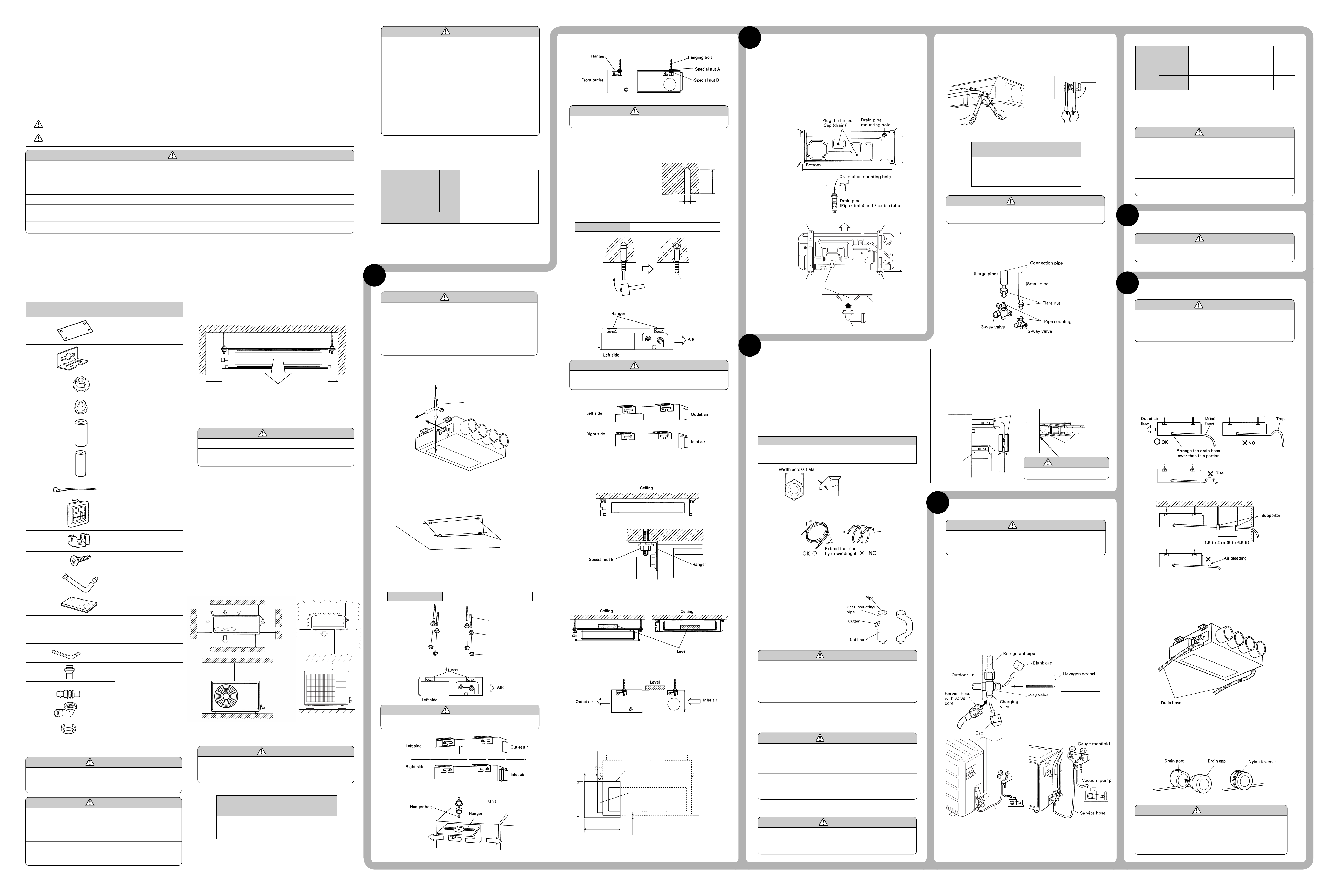
Fig. 8
WARNING
Fasten the unit securely with special nuts A and B.
Installation method (2)
Install the bolts to the ceiling at a place strong enough to hang the
•
unit. Mark the bolt positions from the installation template.
With a concrete drill, drill for
12.7 mm (1/2”) dia.
holes. (Fig. 9)
Insert the anchor bolts into the drilled holes, and drive the pins
•
completely into the anchor bolts with a hammer.
Anchor-Bolt Strength 9.81 to 14.71 N·m (100 to 150 kgf·cm)
Fig. 10
Fig. 9
1.27 mm (ø1/2”)
60 to 70 mm
(2-3/8” to 2-3/4”)
2
OUTDOOR UNIT INSTALLATION
(1)
When the outdoor unit will be exposed to strong wind, fasten it
with bolts at the places indicated by the arrows. (Fig. 16)
(2)
Since the drain water flows out of the outdoor unit during heating
operation, install the drain pipe sold separately and connect it to
an commercial 16 mm hose. (Reverse model only)
(3)
When installing the drain pipe, plug all the holes (
or one places) other than the drain pipe mounting hole in the
bottom of the outdoor unit with putty so there is no water
leakage. (Fig. 16) (Reverse model only)
Fig. 16
[TYPE A]
804 mm
[TYPE B]
Drain cap
Bottom
Air flow
• holes at two
333 mm
343 mm
When the flare nut is tightened properly by your hand, use a torque wrench to finally tighten it.
Fig. 20
Holding
spanner
Torque wrench
Table 4 Flare nut tightening torque
Pipe
Small pipe
Large pipe
Fig. 21
Unit
side
Tightening torque
30.4 to 34.3 N
(310 to 350 kgf
73.5 to 78.4 N
(750 to 800 kgf
·m
·cm)
·m
·cm)
90°
CAUTION
Be sure to connect the large pipe after connecting the
small pipe completely.
(2) Outdoor unit side
Tighten the flare nut of the connection pipe at the outdoor unit
valve connector. The tightening method is the same as that as at
the indoor side.
Fig. 22
Table 5
Pipe length
Heat & Cool
Additional
refrigerant
Between 7.5 m and 25 m, when using a connection pipe other than that
in the table, charge additional refrigerant with 40 g (1.4 oz)/1 m (3.3 ft)
(Reverse cycle model), 20 g (0.71 oz)/1 m (3.3 ft) (Cooling model) as the
criteria.
(Reverse cycle)
Cooling
model
7.5 m
(25 ft)
None
None
10 m
(33 ft)
100 g
(3.5 oz)
50 g
(1.8 oz)
15 m
(49 ft)
300 g
(10.6 oz)
150 g
(5.3 oz)
20 m
(66 ft)
500 g
(17.6 oz)
250 g
(8.8 oz)
CAUTION
When moving and installing the air conditioner, do not
1
mix gas other than the specified refrigerant (R22) inside
the refrigerant cycle.
When adding refrigerant, add the refrigerant from the
2
charging valve at the completion of work.
If the units are further apart than this, correct operation
3
can not be guaranteed.
5
GAS LEAKAGE INSPECTION
CAUTION
After connecting the piping, check the joints for gas
leakage with gas leak detector.
25 m
(82 ft)
700 g
(24.7 oz)
350 g
(12.3 oz)
STANDARD PARTS
The following installation parts are furnished. Use them as required.
INDOOR UNIT ACCESSORIES
Name and Shape Q’ty Application
Installation
template
Hanger
Special nut A
(large flange)
Special nut B
(small flange)
Coupler heat
insulation
(large)
Coupler heat
insulation
(small)
Nylon fastener For fixing the drain hose
Remote
controller
Remote
controller
cord clamp
Tapping screw
(flush heads)
Auxiliary pipe
assembly
Drain hose
insulation
For positioning the indoor
unit
1
For suspending the indoor
unit from ceiling
4
For suspending the indoor
unit from ceiling
4
4
For indoor side pipe joint
(large pipe)
2
For indoor side pipe joint
(small pipe)
1
1
1
For installing the remote
controller cord
10
For installing the remote
10
controller cord clamp
For wiring conduit
(gas side) connection
1
Insulates the drain hose
and vinyl hose connection
1
INDOOR UNIT
(1)
(2)
(3)
Fig. 1
Left
side
(4)
(5)
OUTDOOR UNIT
(1)
(2)
(3)
(4)
(5)
(6)
(7)
(8)
Fig. 2
OUTDOOR UNIT ACCESSORIES
The types of outdoor units are shown in Fig. 2.
300 mm (12”)
or more
Hexagon
wrench
Pipe (drain)
Flexible tube
Drain pipe
Cap (drain)
TYPE A TYPE B
_
1
_
1
_
1
_
1
21
For operating the
refrigerant valve on the
outdoor unit
For outdoor unit drain
piping work (May not be
supplied, depending on
the model.)
CONNECTION PIPE REQUIREMENT
SELECTING THE MOUNTING POSITION
WARNING
Install at a place that can withstand the weight of the
indoor and outdoor units and install positively so that
the units will not topple or fall.
CAUTION
Do not install where there is the danger of com-
1
bustible gas leakage.
Do not install the unit near heat source of heat,
2
steam, or flammable gas.
If children under 10 years old may approach the unit,
3
take preventive measures so that they cannot reach
the unit.
• Use 0.7 mm to 1.2 mm thick pipe.
• Use pipe with water-resistant heat insulation.
• Use pipe that can withstand a pressure of 3,040 kPa.
Install the indoor unit on a place having a sufficient strength so that
it withstand against the weight of the indoor unit.
The inlet and outlet parts should not be obstructed; the air should
be able to blow all over the room.
Leave the space required to service the air conditioner (Fig. 1).
Strong and durable ceiling
Indoor unit
300 mm (12”)
or more
Install the unit where the drain pipe can be easily installed.
Providing as much space as possible between the indoor unit and
the ceiling will make work much easier.
150 mm (6”)
or more
WARNING
Install the unit where it will not be tilted by more than 5°.
1
When installing the outdoor unit where it may
2
exposed to strong wind, fasten it securely.
If possible, do not install the unit where it will exposed to direct sunlight. (If necessary, install a blind that does not interfere with the air
flow.)
Install the outdoor unit in a place where it will be free from being
dirty or getting wet by rain as much as possible.
Install the unit when connection to the indoor unit is easy.
During heating operation, drain water flows from the outdoor
unit. Therefore, install the outdoor unit in a place where the drain
water flow will not be obstructed.
Do not place animals and plants in the path of the warm air.
Take the air conditioner weight into account and select a place
where noise and vibration are small.
Select a place so that the warm air and noise from the air conditioner do not disturb neighbors.
Provide the space shown in Fig. 2 so that the air flow is not blocked.
Also for efficient operation, leave open three of the four directions front, rear, and both sides.
[TYPE A] [TYPE B]
Air
60 cm (2’)
or over
30 cm (1’)
or over
60 cm (2’)
or over
30 cm (1’)
or over
600 mm
(24”)
or more
600 mm
(24”)
or more
300 mm
(12”)
or more
400 mm (16”) or more
30 cm (1’)
or over
CAUTION
The maximum lengths of this product are shown in table1.
If the units are further apart than this , correct operation
can not be guaranteed.
Table 1
Diameter
Small Large
9.53 mm
(3/8in)
15.88 mm
(5/8in)
Maximum
length
25 m
(80 ft)
Maximum height
(between indoor
and outdoor)
15 m
(49 ft)
Right
side
1
INDOOR UNIT INSTALLATION
WARNING
Install the air conditioner in a location which can with-
•
stand a load of at least five times the weight of the main
unit and which will not amplify sound or vibration.
If the installation location is not strong enough, the indoor unit may fall and cause injuries.
If the job is done with the panel frame only, there is a risk
•
that the unit will come loose. Please take care.
1. PIPING CONNECTION DIRECTION AND
PREPARATION
Select piping directions. (Fig. 3)
•
Fig. 3
To rear
To side
To bottom
When bending the piping is difficult, use the auxiliary pipe assembly.
•
2. DRILLING HOLES FOR BOLTS AND
INSTALLING THE BOLTS
Using the installation template, drill holes for bolts (four holes).
•
(Fig. 4)
Fig. 4
3. INSTALLING THE HANGERS
Installation method (1)
•
Fasten the hanging bolts to the ceiling and install special nuts A and B.
Bolt Strength 9.81 to 14.71 N·m (100 to 150 kgf·cm)
Fig. 5
•
Install the hangers to the unit.
Fig. 6
When fastening the hangers, make the bolt positions uniform.
(Example)
Hang the unit.
•
Pass the hanging bolts through the hangers. (Four places)
(1)
Fig. 7
(2)
Slide the unit in the arrow direction and fasten it.
To top
Auxiliary pipe assembly
Installation
template
WARNING
Drilling position
for bolts
Hanging bolt (M10)
Special nut A
Special nut B
M10 Anchor Bolt
(Obtained locally)
Install the hangers to the unit.
•
Fig. 11
WARNING
When fastening the hangers, make the bolt positions uniform.
(Example)
Install the unit
•
Pass the unit hangers over the bolts installed to the ceiling and install
the unit with the special nut B.
Fig. 12
4. LEVELING
Base horizontal direction leveling on top of the unit.
•
Fig. 13
Base vertical direction leveling on the unit (right and left).
•
Fig. 14
5. SERVICE HOLE DIMENSIONS
It shall be possible to install and remove the control box metal.
•
Fig. 15
Reference B
200 mm
(8”)
500 mm (20”)
500 mm
(20”)
Service hole
Control box metal
Reference A
50 mm
(2”)
• Vertical dimension
500 mm from 50 mm below reference A
• Horizontal dimension
500 mm from 200 mm from the left from reference B
603 mm
Drain pipe mounting hole
Bottom plate
Drain pipe
3
CONNECTING THE PIPING
1. FLARE PROCESSING
(1)
Cut the connection pipe with pipe cutters so that the pipe is not
deformed.
(2)
Holding the pipe downward so that cuttings cannot enter the pipe
and remove the burrs.
(3)
Remove the flare nut from the indoor unit pipe and outdoor unit
and assemble as shown in (Table 3) and insert the flare nut onto
the pipe, and flare with a flaring tool.
(4)
Check if the flared part “L” (Fig. 17) is spread uniformly and that
there are no cracks.
Table 3
Flare nut
L dimension
Small pipe
1.8 to 2.0 mm (9.53 mm dia)
Large pipe
2.2 to 2.4 mm (15.88 mm dia)
Small pipe
Large pipe
Fig. 17
Pipe
Small (width across flats 22 mm)
Large (width across flats 27 mm)
2. BENDING PIPES
The pipes are shaped by your hands. Be careful not to collapse them.
Fig. 18
Do not bend the pipes in an angle more than 90°.
When pipes are repeatedly bent or stretched, the material will harden,
making it difficult to bend or stretch them any more. Do not bend or
stretch the pipes more than three times.
When bending the pipe, do not bend it as is. The pipe will be collapsed. In
this case, cut the heat insulating pipe
with a sharp cutter as shown in Fig.
19, and bend it after exposing the
pipe. After bending the pipe as you
want, be sure to put the heat insulating pipe back on the pipe, and secure
it with tape.
Fig. 19
CAUTION
To prevent breaking of the pipe, avoid sharp bends.
1
Bend the pipe with a radius of curvature of 150 mm or
over.
If the pipe is bent repeatedly at the same place, it will
2
break.
3. CONNECTION PIPES
Indoor unit side
(1)
Detach the caps and plugs from the pipes.
CAUTION
Be sure to apply the pipe against the port on the in-
1
door unit correctly. If the centering is improper, the
flare nut cannot be tightened smoothly. If the flare nut
is forced to turn, the threads will be damaged.
Do not remove the flare nut from the indoor unit pipe
2
until immediately before connecting the connection
pipe.
Centering the pipe against port on the indoor unit, turn the flare
nut with your hand.
CAUTION
Hold the torque wrench at its grip, keeping it in the right
angle with the pipe as shown in Fig. 21, in order to tighten
the flare nut correctly.
4. HEAT INSULATION ON THE PIPE JOINTS
(INDOOR SIDE ONLY)
Stick coupler heat insulation (large and small) to the place where
•
connecting pipes.
When using auxiliary piping with large pipe, stick coupler heat insu-
•
lation (large) to the pipe at the two places shown below.
Fig. 23
Reference A
Cover this portion with
heat insulating material
also without fail.
Heat insulating pipe
CAUTION
No gap should remain.
Front outlet
Coupler heat
insulation
(small) on the
pipe
4
Coupler heat insulation
(large) on the pipe.
Large pipe
Small pipe
VACUUM PROCESS
CAUTION
Do not purge the air with refrigerants but use a vacuum
pump to vacuum the installation! There is no extra refrigerant in the outdoor unit for air purging!
1. VACUUM
Remove the cap, and connect the gauge manifold and the
(1)
vacuum pump to the charging valve by the service hoses.
Vacuum the indoor unit and the connecting pipes until the
(2)
pressure in them lowers to below 0.2 kPa (1.5 mmHg).
Disconnect the service hoses and fit the cap to the charging valve
(3)
(Tightening torque : 6.87 to 8.83 N
Remove the blank caps, and fully open the spindles of the 2-way
(4)
and 3-way valves with a hexagon wrench (Torque : 2-way valve:
6.87 to 8.83 N
(100 to 120 kgf
Tighten the blank caps of the 2-way valve and 3-way valve to the
(5)
specified torque (19.62 to 24.53 N
Fig. 24
·m (70 to 90 kgf·cm), 3-way valve: 9.81 to 11.77 N·m
·cm)).
Gauge manifold
LO
HI
Vacuum
pump
Service hose
·m (70 to 90 kgf·cm).
·m (200 to 250 kgf·cm)).
Use a 4 mm
hexagon wrench.
2. ADDITIONAL CHARGE
Refrigerant suitable for a piping length of 7.5 m is charged in the outdoor
unit at the factory.
When the piping is longer than 7.5 m, additional charging is necessary.
For the additional amount, see the table below.
6
INSTALLING DRAIN HOSE
Install the drain hose in accordance with the instructions
in this installation instruction sheet and keep the area
warm enough to prevent condensation. Problems with
the piping may lead to water leaks.
NOTE : INSTALL THE DRAIN HOSE
Install the drain hose with downward gradient (1/50 to 1/100) and so
••
there are no rises or traps in the hose.
Use general hard polyvinyl chloride pipe (VP25) [outside diameter
•
38 mm] and connect it with adhesive (polyvinyl chloride) so that
there is no leakage.
When the hose is long, install supporters.
•
Do not perform air bleeding.
•
Always heat insulate the indoor side of the drain hose.
•
Fig. 25
The outside diameter of the drain port is 38 mm. Use a suitable
•
drain hose.
There is a drain port on both the left and right sides. Select the drain
•
port to match the local conditions.
Fig. 26
When the unit is shipped from the factory, the drain port is on
•
the left side (control box side).
When using the drain port on the right side of the unit, reinstall
•
the drain cap to the left side drain port.
Fig. 27
CAUTION
Always check that the drain cap is installed to the unused drain port and is fastened with the nylon fastener.
If the drain cap is not installed, or is not sufficiently fastened by the nylon fastener, water may drip during the
cooling operation.
CAUTION
Decide the mounting position with the customer as follows:
- Continued on back -
Page 2
7
•
Cut the drain hose insulation at a position approximately 30 mm
from the end with cutters, etc. (Fig. 28-(1))
•
Stick the large drain hose insulation at the drain hose installation
side. (Fig. 28-(2))
•
Stick the small drain hose insulation at the drain cap side (Fig. 28-(3))
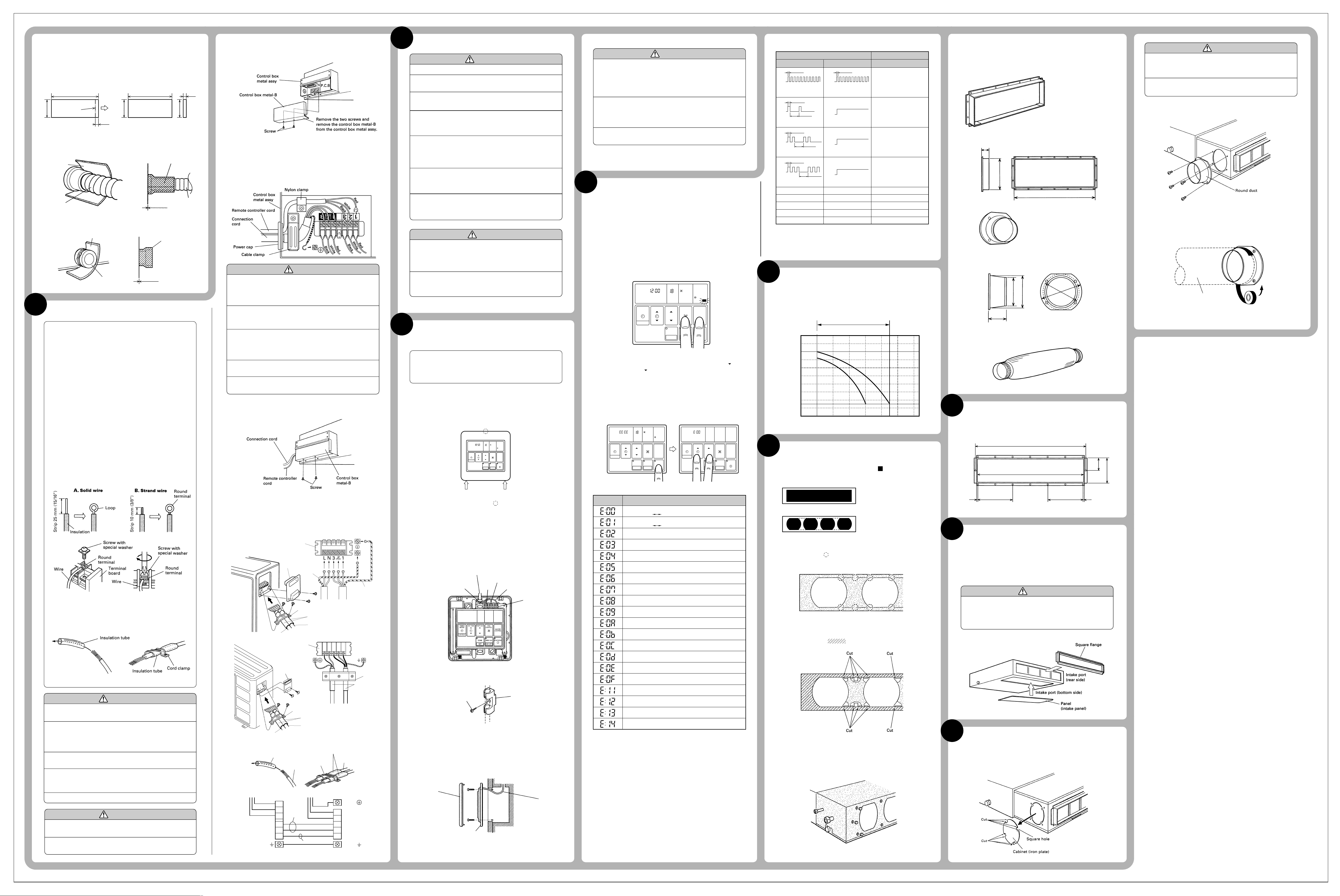
Fig. 28-(1)
450 mm (17-23/32”) 420 mm (16-17/32”)
Cut line
170 mm
(6-11/16”)
170 mm
(6-11/16”)
30 mm (1-3/16”)
Fig. 28-(2)
Drain hose
insulation
(large)
Unit
Drain hose
Unit
Drain hose
insulation (large)
0 mm (0”)
Fig. 28-(3)
Unit
Drain hose insulation (small)
Drain cap
Unit
0 mm (0”)
Drain hose
insulation (small)
ELECTRICAL WIRING
HOW TO CONNECT WIRING TO THE TERMINALS
A. For solid core wiring (or F-cable)
(1)
Cut the wire end with a wire cutter or wire-cutting pliers,
then strip the insulation to about 25 mm (15/16”) of expose the solid wire.
(2)
Using a screwdriver, remove the terminal screw(s) on the
terminal board.
(3)
Using pliers, bend the solid wire to form a loop suitable
for the terminal screw.
(4)
Shape the loop wire properly, place it on the terminal
board and tighten securely with the terminal screw using
a screwdriver.
B. For strand wiring
Cut the wire end with a wire cutter or wire-cutting pliers,
(1)
then strip the insulation to about 10 mm (3/8”) of expose
the strand wiring.
Using a screwdriver, remove the terminal screw(s) on the
(2)
terminal board.
Using a round terminal fastener or pliers, securely clamp
(3)
a round terminal to each stripped wire end.
Position the round terminal wire, and replace and tighten
(4)
the terminal screw with a screwdriver.
Fig. 29
HOW TO FIXED CONNECTION CORD AND POWER
CORD AT THE CORD CLAMP
After passing the connection cord and power cord through
the insulation tube, fasten it with the cord clamp.
Fig. 30
30 mm
(1-3/16”)
170 mm (6-11/16”)
Drain hose
1. INDOOR UNIT SIDE
(1)
Remove the control box metal-B from the control box metal
assy.
Fig. 31
Connection cord and remote controller cord connections.
(2)
Clamp the connection cord with the cable clamp and the remote
•
controller cord with the nylon clamp.
Connect the connection cord to the terminals with the white
•
characters on the terminal nameplate.
Connect the remote controller cord to the terminals with the
•
black characters on the terminal nameplate.
Fig. 32
CAUTION
1
Tighten the indoor unit connection cord (to the outdoor unit) and power supply indoor and outdoor unit
terminal board connections firmly with the terminal
board screws. Faulty connection may cause a fire.
2
If the indoor unit connection cord (to the outdoor
unit) and power supply are wired incorrectly, the air
conditioner may be damaged.
3
Wire the indoor unit connection cord (to the outdoor
unit) by matching the numbers of the outdoor and
indoor units terminal board numbers as shown in
(Fig. 32).
4
Ground both the indoor and outdoor units by attaching a ground wire.
5
Unit shall be grounded in compliance with the applicable local and national codes.
(3)
Control box metel-B installation
Fasten control box metal-B with the two screws.
For the connection cord outlet port see Fig. 33.
Fig. 33
2. OUTDOOR UNIT SIDE
(1)
Remove the terminal cover of the outdoor unit, and insert the end
of the connection cord and the power cable into the terminal
board.
(2)
Fasten the connection cord with the cord clamps, and install
the terminal cover.
Fig. 34
Terminal board
Terminal
cover
Power cable
Terminal board
Green/ Yellow
Power cable
Cord clamp
Insulation tube
Connection cord
Connection
cord
NL32
(N)
Green/
Yellow
1
8
9
POWER
WARNING
The rated voltage of this product is 1ø 220-240 V 50Hz.
1
Before turning on verify that the voltage is within the
2
198 to 264V range.
Always use a special branch circuit and install a special
3
receptacle to supply power to the air conditioner.
Use a special branch circuit breaker and receptacle
4
matched to the capacity of the air conditioner.
(Fuse/Breaker capacity : 30A)
The special branch circuit breaker is installed in the per-
5
manent wiring.
Always use a circuit that can trip all the
poles of the wiring and has an isolation distance of at
least 3mm between the contacts of each pole.
Perform wiring work in accordance with standards so
6
that the air conditioner can be operated safely and
positively.
Install a leakage special branch circuit breaker in ac-
7
cordance with the related laws and regulations and
electric company standards.
CAUTION
The power source capacity must be the sum of the
1
air conditioner current and the current of other electrical appliances. When the current contracted capacity is insufficient, change the contracted capacity.
When the voltage is low and the air conditioner is
2
difficult to start, contact the power company the voltage raised.
REMOTE CONTROLLER
INSTALLATION
When mounting the remote controller, refer to the enclosed REMOTE CONTROLLER INSTALLATION INSTRUCTION SHEET. Then, make the necessary settings on both
the remote controller and the main unit.
Insert the end of a flat blade screwdriver at the arrow parts of the
•
groove at the side of the remote controller case and remove the
remote controller case top by turning the screwdriver.
Disconnect the remote controller cord from the remote controller
•
terminal board.
Fig. 35
CLOCK
TEMP
NON STOP
TIMER
MODE
CLOCK ADJUST
(1)
When remote controller exposed
1)
Make a notch in the thin part ( part of Fig. 35) at the remote
controller case top and bottom with nippers, file, etc.
2)
Connect the remote controller cord to the remote controller
terminal board specified in (Fig. 36).
3)
Clamp the remote controller cord sheath with the binder
(small) as shown in Fig. 36.
4)
Cut off the excess binder.
5)
Clamp the remote controller cord to a wall, etc. with the remote controller cord clamp furnished (Fig. 37).
Fig. 36
Remote controller cord
Binder (small)
21
SET TIME TEMP./DAY FAN
ZONE
SET
Red
°C
AUTO
HIGH
CONTROL
ENERGY SAVE
DAY OFF
COOL
DEFROST
MASTER
CONTROL
START/STOP
White
Black
Remote controller
terminal board
10
CAUTION
Do not bundle the remote controller cord, or wire
1
the remote controller cord in parallel, with the indoor unit connection wire (to the outdoor unit) and
the power supply cord. It may cause erroneous operation.
When installing the remote controller and cord near
2
a source of electromagnetic waves, separate the
remote controller from the source of the electromagnetic waves and use shielded cord.
Do not touch the remote controller PC board and PC
3
board parts directly with your hands.
TEST RUNNING
1. REMOTE CONTROLLER
Supply power to the crankcase heater 12 hours before the start
•
of operation in the winter.
For test running, when the remote controller FAN CONTROL
•
button and MASTER CONTROL button are pressed
simultaneously for more than three seconds when the air
conditioner is not running, the air conditioner starts and TEST is
displayed on the remote controller display.
However, the TEMP./DAY setting button does not function, but
all other buttons, displays, and protection functions operate (Fig.
39).
Fig. 39
CLOCK
NON STOP
21
TIMER
SET TIME TEMP./DAY FAN
MODE
CLOCK ADJUST
When EE : EE blinks at the current time display, there is an error
•
inside the air conditioner. If the SET TIME button ( ) and
TEMP./DAY button ( ) are pressed simultaneously for more than
three seconds, the self diagnosis check will start and the error
contents will be displayed at the current time display (Fig. 40).
When the operation lamp lights, press the START/STOP button
and after operation lamp goes off, perform the same operation
(Fig. 40). Process the error contents by referring to (Table 6).
Fig. 40
CLOCK
NON STOP
21
TIMER
MODE
CLOCK ADJUST
Stop Operation.
TEMP
°C
SET TIME TEMP./DAY FAN
CONTROL
ZONE
ENERGY SAVE ENERGY SAVE
SET
DAY OFF
AUTO
HIGH
Error code
Communication error
(indoor unit remote controller)
Communication error
(indoor unit outdoor unit)
Room temperature sensor open
Room temperature sensor shortcircuited
Indoor heat exchanger temperature sensor open
Indoor heat exchanger temperature sensor
shortcircuited
Outdoor heat exchanger temperature sensor open
Outdoor heat exchanger temperature sensor
shortcircuited
Power source connection error
Float switch operated
Outdoor temperature sensor open
Outdoor temperature sensor shortcircuited
Discharge pipe temperature sensor open
Discharge pipe temperature sensor shortcircuited
TEMP
°C
ZONE
SET
COOL
DEFROST
MASTER
CONTROL
START/STOP
Table 6
Error contents
AUTO
HIGH
CONTROL
DAY OFF
21
TIMER
MODE
CLOCK ADJUST
COOL
DEFROST TEST
MASTER
CONTROL
START/STOP
SET TIME TEMP./DAY FAN
CONTROL
SET
DAY OFF
AUTO
MASTER
CONTROL
START/STOP
11
12
Table 7
Error display
Error contentsLED2LED1
0.1 sec.
ON
OFF
0.5 sec.
ON
OFF
ON
OFF
ON
OFF
4 quick flash repeated
5 quick flash repeated
6 quick flash repeated
7 quick flash repeated
8 quick flash repeated
2 sec.
0.5 sec.
2 sec.
0.5 sec.
2 sec.
0.1 sec.
ON
OFF
Quick flash continuedQuick flash continued
ON
OFF
Lighting continued1 quick flash repeated
ON
OFF
Lighting continued2 quick flash repeated
ON
OFF
Lighting continued3 quick flash repeated
Lighting continued
Lighting continued
Lighting continued
Lighting continued
Lighting continued
Model abnormal or
EEPROM abnormal
Power source
connection error
Discharge temperature
sensor error
Outdoor heat exchanger
temperature sensor error
Outdoor temperature sensor error
Communication signal error
Indoor unit error
Discharge temperature abnormal
High pressure abnormal
When the fault is cleared, the LED lamp goes off.
However, for discharge pipe temperature abnormal and high pressure abnormal, the LED lamp lights continuously for 24 hours, as
long as the power is not turned off.
STATIC PRESSURE
CHARACTERISTIC
Fig. 41 FAN PERFORMANCE AND AIR FLOW
EXTERNAL STATIC PRESSURE
RECOMMENDED RANGE
(R/sec)
(m
3
/h)
196 (Pa)
(mm Aq)
EXTERNAL
STATIC
PRESSURE
20
18
16
14
12
10
8
6
4
3
2
0
167 222 278 333 389 444 500
HI
LO
600 800 1,000 1,200 1,400 1,600 1,800
AIR FLOW
OUTLET DUCT CONNECTION
1. DUCT INSTALLATION PATTERN ( CUT PART)
Fig. 42
(1) Square duct
(2) Round duct outlet × 4
(This is the factory setting.)
2. WHEN USING AS A SQUARE DUCT
Cut the slit seam with a cutter.
(1)
Fig. 43
(2)
Turn up the insulation around the points to be cut according to
the outlet port shape working points so that the insulation dose
not stick out at the part.
Fig. 44
3. SPECIAL ITEMS
CAUTION
When connecting the square duct and round duct, use the optional
When removing the cabinet (iron plate), be careful not
square flange or round flange and flexible duct.
Fig. 46
1
to damage the indoor unit internal parts and surrounding area (outer case).
Square flange
When processing the cabinet (iron plate), be careful
Model name : UTD-SF045
(P/N 9054229009)
(P/N 9098180007)
2
not to injure yourself with burrs, etc.
Install the round flange (option parts) to the fresh air intake.
(2)
Fig. 50
40 mm
(1-19/32”)
• Square flange dimensions
204 mm
(8-5/16”)
1,065 mm (41-15/16”)
Round flange
Model name : UTD-RF204
(P/N 9093160004)
Connect the duct to the round flange.
(3)
Seal with a band and vinyl tape, etc. so that air dose not leak
(4)
from the connection.
Fig. 51
• Round flange dimensions
ø205 mm
(8-7/8”)
Duct
85 mm
(3-11/32”)
ø195 mm
(7-11/16”)
ø205 mm
(8-1/16”)
ø235 mm
(9-1/4”)
Flexible duct
Model name : UTD-RD202
(P/N 9074165004)
98
ø200 mm (7-7/8”)
L 2 m (78-3/4”)
13
0
Fig. 47
10 mm
(13-32”)
INTAKE PORT REAR COVER
DIMENSIONS
1078 mm (42-7/16”)
1063 mm (41-27/32”)
384 mm
(13-11/16”)
384 mm
(13-11/16”)
10 mm
(13-32”)
102 mm
(4-1/32”)
204 mm
(8-1/32”)
14
INTAKE PORT
The square flange (rear side) and panel (intake panel) are instal-
(1)
led at the factory at the places shown in Fig. 48.
When taking in air from the bottom side, reinstall the square
(2)
flange (rear side) and panel (intake panel).
CAUTION
When air is taken in from the bottom side, the operating
sound of the product will easily eater the room.
Install the product and intake grilles where the affect of
the operating sound is small.
Fig. 48
Use VW-1, 0.5 to 1.0 mm thick, PVC tube as the insulation tube.
WARNING
1
Before starting work, check that power is not being supplied to the indoor unit and outdoor unit.
2
Match the terminal block numbers and connection cord
colors with those of the indoor unit side.
Erroneous wiring may cause burning of the electric
parts.
3
Connect the connection cords firmly to the terminal
block. Imperfect installation may cause a fire.
4
Always fasten the outside covering of the connection
cord with cord clamps. (If the insulator is clamped,
electric leakage may occur.)
5
Always connect the ground wire.
CAUTION
1
Select power cable matched to the fuse capacity.
(Install in accordance with standard.)
2
Use VW-1, 12 mm diameter, 0.5 to 1.0 mm thick, PVC
tube as the insulation tube.
Power cable
Insulation tube
After passing the connection
cord through the insulation
tube, fasten it with the cord
clamp.
Remote controller Power supply
Black
White
Red
(N)
Indoor unit
side terminal
Terminal
cover
Connection
cord
3
2
Power line
1
3
2
1
Cord
clamp
Insulation tube
Connection cord
Insulation tube
(Use VW-1, 0.5 to 1.0 mm thick,
PVC tube as the insulation tube)
Power
cable
Cord clamp
Connection
cord
Connection cord
EARTH
L
N
3
2
(N)
Control line
1
EARTH
Outdoor unit
side terminal
Cord clamp
Insulation
tube
Fig. 37
Remote controller cord
Tapping screw (flush heads)
(2)
When remote controller cord embedded
1)
Embed the remote controller cord and box.
2)
Pass the remote controller cord through the hole at the remote
Remote controller
cord clamp
controller case bottom and install the cord to the box. (Fig. 38)
3)
Connect the remote controller cord to the remote controller
terminal board specified in (Fig. 36).
Fig. 38 [Example]
Remote controller
case top
Remote
controller
cord
Remote controller case bottom
After wiring work is complete, return the remote controller case
•
top to its original state.
Outdoor high pressure abnormal
Discharge pipe temperature abnormal
Model abnormal
Indoor fan abnormal
Outdoor signal abnormal
Outdoor EEPROM abnormal
To stop test running, press the START/STOP button.
•
For the operation method, refer to the operating manual and per-
•
form operation check.
Check that there are no abnormal sounds or vibration sounds
•
during the test running.
2. OUTDOOR UNIT
When the outdoor temperature drops, the outdoor unit's fan may
switch to low speed.
ERROR: HEAT & COOL MODEL (REVERSE CYCLE) ONLY
The LED lamps operate as follows (Table 7) according to the error
contents.
The LED lamps are on the outdoor unit board.
Cut with nippers and remove the sheet metal.
(3)
Since there is a slit in the insulation, use radio pliers, tweezers,
(4)
etc. to stretch tight the screw hole part used when installing the
round flange and square flange when connecting the duct.
Fig. 45
15
FRESH AIR INTAKE
(Processing before use)
When taking in fresh air, cut a slit shaped cabinet in the left side
(1)
of the outer case as shown in Fig. 49 with nippers.
Fig. 49
PART NO. 9357874081
 Loading...